滁州安瑞汇龙申克说明书
瑞克科自动闭合系统产品说明书
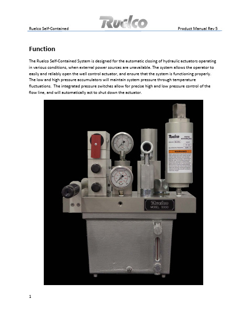
Ruelco Self-Contained Product Manual Rev 5FunctionThe Ruelco Self-Contained System is designed for the automatic closing of hydraulic actuators operating in various conditions, when external power sources are unavailable. The system allows the operator to easily and reliably open the well control actuator, and ensure that the system is functioning properly. The low and high pressure accumulators will maintain system pressure through temperature fluctuations. The integrated pressure switches allow for precise high and low pressure control of the flow line, and will automatically act to shut down the actuator.Ruelco Self-Contained Product Manual Rev 5Design Features-Manifold design with no external tubing on the unit reduces leak points as well as reduces likelihood of damage at jobsite.-All material is NACE rated using anodized 6061-T6 aluminum and 316 stainless steel.-Low and high pressure relief valves preset to desired pressure to prevent damage to actuator or low pressure equipment.-Quick Exhaust for fast response time-Solenoid operated control (50 psi Max)-40 micron suction filter and magnetic drain plug to prevent contamination of the system.-Stainless steel gauges with dual scales.-Integrated pressure switches allow for flow line control without additional components and reduce the tubing required for install.-Seal material used allows full functionality from -50° F to 180° F (Optional seal materials available upon request).-High and low pressure accumulator accommodates for thermal expansion volume changes.-System is easily charged with use of red anodized latch.-Sight glass on tank allows for visual level indication of system.-Check valve in suction tube ensures a constant prime of the pump.Ruelco Self-Contained Product Manual Rev 51 High Pressure Hand Pump2 1.6 Gallon Aluminum Reservoir3 High Pressure Relief Valve4 Low Pressure Relief Valve5 Manual Reset Relay6 Regulator7 4.8 cu in LP Spring Accumulator8 0 - 5,000 psi Gage9 0 - 60 psi Gage (Standard)10 Vent/ Fill Cap 11 Sight Glass12 Low Pressure Switch13 High Pressure Switch14 HP Gas Charge Accumulator15 Fuse Plug16 40 Micron Filter17 Suction Check Valve18 Magnetic Drain Plug19 Quick Exhaust20 Solenoid Operator (12VDC or 24 VDC)Ruelco Self-Contained Product Manual Rev 5 SpecificationsTemperature Range -50 F to 180 FHP Circuit Max Pressure 5,000 psiLP Circuit Max Pressure 120 psiMin Pressure 30 psiLP Relief Valve Range 50-150 psiHP Relief Valve Range 2,000 - 6,000 psiRange (Optional) 250 - 3,000 psiReservoir Capacity 1.6 gallonsCapacity (Optional) 2.5 gallonsLP Accumulator Capacity 4.8 cu inHP Accumulator Capacity 6 cu inCapacity (Optional) 16 cu inSolenoid Voltage 12VDC or 24 VDCNormally Open Wattage 1.8 wattsRating Class 1 Div 1 A,B,C,DNEMA 4Max Pressure 50 psiPump Displacement .39 cu in/ strokeFuse Plug Temperature Range 158°F to 283°FPressure Switch Repeatability 1%Deadband 8%Cv .13Max Process WP 5,000 psiMax Process WP (Optional) 10,000 psi (316 Only)Burst Pressure 5,000 psiBurst Pressure (Optional) 10,000 psi (316 Only)Standard Ranges 1G ( 50 - 200 psi)1Y ( 175 - 450 psi)2G ( 450 - 1,750 psi)2Y ( 1,500 - 3,000 psi)High Pressure 2P ( 2,000 - 5,000 psi)2S (4,500 - 10,000 psi)Ruelco Self-Contained Product Manual Rev 5 InstallationEvery Ruelco Self-Contained unit is 100% function tested using a fully charged gas accumulator. After testing, the gas accumulator is fully discharged and the each unit is shipped with a clean and empty tank.NOTE: The gas charge accumulator must be pre-charged at the time of commissioning at the operating temperature for proper function of the unit. Ruelco can recommend a pre-charge and operating pressure based upon the actuator minimum hold open pressure, maximum actuator pressure, and the environmental conditions. For actuator volumes/ systems over 150 cu in, Ruelco recommends using the 16 cu in option in order to optimize the functional temperature range of the unit. Charge kits are available P/N: 20-205-000.Ruelco recommends using Shell Aero 41 or equivalent.ConnectionsOnly two connection lines are necessary to install and operate the unit.1. Connect the actuator to one of the three high pressure outlet ports on the manifold or if installed, the “To Actuator” port of the quick exhaust.2. Connect the process flow line to the back of the pressure switch manifold (if applicable).Gas Charge Accumulator Charging Procedure1.Remove Gas Valve Guard from top of the Accumulator then remove the yellow gas valve stem cap.2. Using the two ¾” open-ended wrenches, open the accumulator gas valve by turning the top hex counterclockwise.3. Connect charging gooseneck fitting to a nitrogen tank with a pressure gauge in line.4. Connect the swivel nut on the gooseneck fitting to the gas valve.5. Slowly open nitrogen supply valves until in line pressure gauge reads required pressure.6. Using the two ¾” open-ended wrenches, completely close the accumulator gas valve by turning the top hex clockwise.7. Close all valves leading to the nitrogen supply tank. Vent any nitrogen that remains in the lines.8. Remove the accumulator from the swivel nut on gooseneck fitting.9. Install the yellow gas valve stem cap, and then reinstall the gas valve guard.OperationFor maximum performance and system life, prior to connecting the system to the actuator, ensure that the actuator and connecting tubing is fully flushed and cleaned. This will prevent debris from entering the system through the actuator when draining as well as prevent mixing hydraulic oils or other fluids within the system. The unit is shipped dry and is tested using clean and filtered hydraulic oil.Prior to operating the system, ensure that the low pressure and high pressure relief valves are set to the needs of the actuator.Flowline pressure should be connected to the ¼” npt port on the pressure switch base.If a nitrogen pre-charge is not determined by the customer or end user, Ruelco recommends charging the accumulator with nitrogen to 50% of the minimum actuator hold open pressure.Start-up Manual Mode1. Lift the latch handle into the horizontal position.2. Stroke the pump until the desired low pressure output is obtained. The low pressure circuit is preset to 30 psi via the regulator.Note: If the flow line pressure is between the high and low set points of the pressure switches, the latch will fall into an armed position. If the flow line pressure is out of the pressure switch set points, the latch will remain in the “Manual” position. If this occurs, the system is not in “Automatic mode” and can only be shutdown manually.3. Continue to stroke the pump until the actuator is fully opened.4. The latch should be in the armed hanging position indicating that the system is in the “Set” state.5. Ruelco recommends that the pump handle be left in the upward position to prevent any high pressure leakage, causing slow bleed down of the system.ShutdownHigh or Low PressureThe system will automatically shut down if the flowline pressure deviates outside of the pressure switch set points. The pressure switches are independently adjustable for both high and low pressure control, by screwing in or out the adjustment plug. The ranges can also be easily changed by changing the springs or piston seals. Once the flow line pressure rises or falls outside the parameters set by the pressure switches, the pilot signal holding the latch handle will vent and shut down the system. The latch handle will return to the downward locked state.Fuse PlugA fuse plug comes installed in the low pressure outlet port of the regulator and will vent the low pressure hydraulic signal, if fire activated. The fuse plug can be set to a variety of temperatures ranging from 158° F to 350° F. The fuse plug will have to be replaced after use.Manual Push RelayThe relay latch can be pushed inward, manually venting the pilot control signal. This will shut down the low pressure and high pressure circuit, closing the connected actuator.SolenoidAn integrated manifold mounted solenoid valve can be used as a remote operated shutdown. The normally open solenoid is mounted to the relay and will vent the pilot signal upon loss of an electric signal. This will shift the relay and shut down the system. The solenoid is available in a 12VDC or 24VDC option.ESD Valve (Not Included)An optional external ESD valve can be connected to the low pressure output on the manifold. If this valve is activated manually, the low pressure signal will be lost and the shut down the system.Ruelco Self-Contained Product Manual Rev 5Spare Parts/ Repair ListDescription Part Number Qty Required Regulator 5001-05000 1LP Spring Accumulator 5002-05000 1Relay 5003-05000 1Pressure Switch 5004-XXXX0 1Quick Exhaust 5005-05000 1Solenoid Valve 5003-S5000 1Fuse Plug 2102-25XXX 1HP Gas Charge Accumulator 2400-L5000 1HP Relief Valve 7500-2X000 1LP Relief Valve SC-055-000 1Magnetic Drain Plug SC-070-000 1Pump w/ SS Shaft 50-070-000 140 Micron Filter SC-024-040 1Suction Check Valve SC-023-000 1Reservoir 50-003-000 1Sight Glass SC-077-000 10-60 psi Gauge SC-075-060 10-5000 psi Gauge SC-076-000 1Handle SC-072-000 1Mounting Bracket 50-100-000 1Repair Kit f/ Regulator SC-044-000 1Repair Kit f/ LP Spring Accumulator SC-013-000 1Repair Kit f/ Relay SC-016-000 1Repair Kit f/ Pressure Switches 50-015-000 1Repair Kit f/ HP Gas ChargeAccumulator 20-204-000 1Repair Kit f/ HP Relief Valve 75-015-000 1Repair Kit f/ Quick Exhaust 50-047-000 1Repair Kit f/ Solenoid Valve 50-064-000 1Repair Kit f/ LP Relief Valve SC-054-000 1Repair Kit f/ Pump SC-021-000 1Repair Kit f/ Sight Glass SC-065-000 1Tank Gasket SC-022-000 1Gas Charge Kit 20-205-000 1Side View of BracketBack View of 3” -7” Square Mounting SlotsTROUBLESHOOTINGTrouble Possible Causes Corrective Repair Instructions Cannot Charge System 1. Low Oil Level - Fill with oil until aboveminimum level2. No Power to Solenoid - Check solenoid connections3. Clogged Filter - Remove Tank and clean filter4. Process Pressure out of Range - Check that process pressure isin between Pressure switch SetPoints5. Stuck Check Valve - Remove Pump and lightlydepress suction check ball Losing System Pressure 1. Hydraulic leak in external lines - Check all fitting connections2. Pressure Switch tripped High or Low - Check sense pressure gauge and adjust set points if needed3. Thermal expansion - Check HP accumulator pre-charge is set correctly- Check HP relief valve is setsufficiently above the maxanticipated control pressure 4. Low Pressure Leaks - Check that low set pressure isabove 25 psi (minimum to holdrelay open)- Check LP relief valve is setsufficiently above the lowpressure control circuit5. Low Pressure Rises6. High Pressure Leaks - Clean Regulator /Change Seat - Make sure pump handle is in the upward position- Ensure proper torque on Pump 20 ft*lbs。
滁州安瑞汇龙申克说明书
Set Time(时间设置)
注:程序功能和标定功能的详细菜单用光标键移动,进行选择。
B=当选择批量操作时,辅助功能将被加入主菜单中。
Abort Batch(中止批量)
Deselect Batch(退出批量)
喂料速率 I I = 1000kg/h
喂料速率% Ir Ir = 50.00 % 2)
流量计负荷 Q Q = 10.000 kg/m
流量计负荷% Qr Qr = 50.00 % 2)
皮带速度 V V = 0.0500 m/s
L:有效称量段长度(m)
C:比例系数(又称结构系数)
根据惠更斯桥路原理的电阻应变传感器,其电信号输出又与所受重力大小成正比。因此,称重传感器输出的电信号就是皮带瞬时负荷的代表量。
另外,调速秤的瞬时给料量度Qt为:
Qt=qtVt (Kg/s)
式中:Vt:皮带瞬时速度(m/s)
因而,在一段时间秤的累计给料量Q: Q=∫Qt 值作为测量值输入运算控制器,与设定值进行比较,运算控制器即可根据偏差大小和方向,输出相应调节信号来改变皮带的速度,使给料量趋向最终达到设定的目标值,从而实现了自动定量给料的目的。
如果几个事件同时出现,显示内容根据下面的优先级别确定。
优先级顺序:ALARM,WARNING 1,WARNING 2。
操作
应答事件。
如果出现几个事件,需要一个个应答。
显示事件信息内容
调用功能菜单。
移动功能选项,直到“Display Event”进入下行显示器。
进入功能。
右边 显示可选择的内容
选择显示内容
K和K申克秤说明书

克秤操作说明书第一章设备简介申克秤简介申克秤是申克公司应用科里奥利原理开发的一种煤粉喂料计量系统。
煤粉由煤粉仓进入叶轮给料机时,首先经过内置搅拌器,被充分流态化,使其畅通,由叶轮给料机实现稳定喂料,进入科里奥利质量流量计被计量后进入煤粉输送管道,输送至窑头或分解炉。
测得的流量信号(实际值)输入MULTICONT 测控系统,实际值与设定值在系统中进行比较,及时输出反馈信号,调节叶轮给料机转速,实现稳定喂料。
煤粉由流量计流出后,经过一段弯管进入输煤管道,由于喷嘴两边的正负压差(喷嘴位置需在安装调试时确定),这样煤粉可以较容易地被输送。
同时,从喷嘴靠罗茨风机端引出一条正压管线,对叶轮给料机内施加一个小的气压,使下料更为顺畅。
叶轮与外壳间隙仅,被煤粉填充,可以保持叶轮给料机上下的压差,保证下料流畅及稳定。
该喂煤系统的叶轮给料机与煤粉仓出料管之间有一闸板用法兰联接,流量计与叶轮给料机出料管之间、流量计出料管与煤粉输送管线之间也用法兰联接,无需其它安装支架,安装高度低,安装和折卸维修方便;密封性能好,保持煤粉仓下的环境。
我公司12000TPD 生产线共有三台申克秤,一台在煤粉制备车间供窑头燃烧器用煤,型号为Multicor-K120 ,两台在窑尾预热器处供分解炉用煤,型号为Multicor-K80 。
术语定义Disocont: 煤粉秤计量仪表型号Multicell: 带搅拌器的星形喂料系统Multicor-K80: 煤粉秤计量单元型号,“ K”代表煤粉计量系列,80 为流经计量单元的物料流量为80m3/hAgitator: 搅拌器Star Feeder: 星形下料器Optional Dryer: 压缩空气干燥器Coriolis: 科里奥立力Conveying Air: 输送空气Compress Air: 压缩空气Mode OP: 本地操作模式Mode Normal: 中控操作模式Volume Mode: 容积方式Gravimetric Mode: 称重方式:Schenck: 提供的煤粉秤控制软件第二章设备结构设备组成Mulitcor-K80煤粉秤煤粉计量系统外形如图1所示,Multicor-K80系列组件按功能划分主要由四部分组成:2.1.1 MUTICELL rotary feeder (MUTICELL 旋转喂料系统),由Integrated Drive(机电一体化驱动单元)和Star Feeder(星形回转下料器)组成,如图2所示。
申克定量给料机说明书

TDGSK型定量给料机操作手册滁州安瑞汇龙电子有限公司第一章概述:1)概述TDGSK型定量给料机能自动按照预定的程序,根据设定的给料量自动调节流量使之跟踪设定值,以恒定的给料速率连续不断地输送散状物料,实现定量给料、自动计量和累计等功能。
TDGSK型定量给料机精度高、适应能力强、长期稳定性好可靠性高,尤其在条件恶劣的环境下能正常工作。
可广泛应用于水里、建材、矿山、化工、粮食等行业。
型号说明:TDGSK□□□□□□□料斗序号料斗型号(S、T、V)主从滚筒中心距(dm)皮带宽度(dm)M(重型)、L(轻型)定量给料机2)主要技术参数与功能:●给料精度:±0.5%●主电源:380Vdc10%,50HZ2%●仪表电源:24Vdc±5%,1A●使用环境:秤体—30℃~70℃控制柜0℃~45℃●仪表型号:INTECONT PLUS VEG20610●模拟输入:流量设定值4~20mA●模拟输出:1.流量反馈4~20mA2.控制信号4~20mA●脉冲输出:+24V,100mA,脉冲宽度可调(50~1000ms之间),MAX10Hz。
●开关量输入(无源):外部启动信号,释放信号等。
●开关量输出:MIN信号,MAX信号,故障信号,运行信号等。
●显示:荧光显示,2行20个字符,6mm高●能够显示故障信息●停电永久保持信息3)工作原理定量给料机主要由秤体、称重和测速传感器、控制仪表组成,对于粉状或粘湿性物料,尚需配置预给料机。
当系统进入正常工作状态,物料随皮带被拖出布于皮带的工作面上。
此时称量段上瞬时平均物料重G通过称量机构成线性关系作用在称重传感器上。
传感器所受的重力Pt为:Pt=CqtL(Kg)式中:qt:皮带称量段上的瞬时负荷(Kg/m)L:有效称量段长度(m)C:比例系数(又称结构系数)根据惠更斯桥路原理的电阻应变传感器,其电信号输出又与所受重力大小成正比。
因此,称重传感器输出的电信号就是皮带瞬时负荷的代表量。
申克称操作规程

申克称操作规程申克(Shenke)是一家制造机械设备的公司,为了确保生产效率和产品质量,公司制定了一系列操作规程。
一、安全操作规程1. 所有员工必须佩戴个人防护装备,如安全帽、防护眼镜和耳罩等。
在工作区域外的员工严禁进入。
2. 熟悉相关机械设备的操作说明书,并按照说明书进行正确操作。
3. 严禁在设备运行时进行维修或调整,必须停机后才能进行。
4. 操作前必须检查设备的安全装置是否完好,如果有发现故障必须及时通知维修人员。
5. 操作过程中禁止穿戴松散的衣物,以免发生事故。
6. 使用手动工具时应注意安全,禁止随意丢弃或乱放。
二、设备操作规程1. 启动前,必须检查设备是否正常工作,如发现异常现象需及时报修。
2. 严禁在设备运行时进行加工物料的添加或调整。
3. 运行过程中,需按照操作流程进行操作,不能随意更改。
4. 定时清洁设备,保持设备干净整洁,减少故障发生的可能性。
5. 设备停机前,必须将所有刀具和工具收拾整理,清理工作区域。
三、质量控制规程1. 操作人员必须熟悉产品质量标准,并按照标准进行操作。
2. 在加工过程中,必须按照工艺要求进行加工,不能随意调整。
3. 检验每一道工序的合格率,确保产品质量。
4. 如发现产品不合格,必须及时停止生产,并进行原因分析。
5. 操作人员应严格按照质量控制规程进行记录和报告,确保质量管理的有效性。
四、设备维护规程1. 每天开始工作前,必须检查设备的工作状态,如有异常需及时排除。
2. 每周进行设备保养,包括清洁、润滑、更换易损件等。
3. 长期停用设备时,必须进行全面的检查和维护工作。
4. 维修人员必须进行相关岗位培训,并持有相关的证书。
5. 对设备进行维护时,必须使用合适的工具和设备,严禁乱用工具。
五、操作规程执行和管理1. 公司将定期进行操作规程执行情况的检查和评估,对执行良好的员工进行奖励或表彰。
2. 对不按照操作规程进行操作的员工进行纪律处分,直至解雇。
3. 严禁将操作规程外泄或随意更改,一经发现将采取法律措施进行追究。
申克仪表简单说明书

申克仪表说明书控制方式:本地控制方式(键盘模式)/远程控制方式(非键盘模式)标定模式:容积模式(标定模式)/重量模式(非标定模式)按键说明启动停止选择上下显示器显示内容,选择功能复位计数器相当于FUNC键。
调用分配功能和时间按信息相当于DEL键,应答事件信息删除输入数字相当于ESC键,退出功能相当于ENT键,确认输入有效1、开启键盘模式:将仪表设为本地模式(键盘模式):由现场操作,中控不能操作。
按菜单键“”进入主菜单。
然后用上下键找到“Start Keyboard Mode”按确认键“”。
此时仪表左上方会出现一个小方格。
说明在键盘模式。
2、关闭键盘模式:按菜单键“”进入主菜单。
然后用上下键找到“Stop Keyboard Mode”按确认键“”。
此时仪表左上方小方格会消失。
说明在非键盘模式。
此时仪表将由中控控制。
3、开启容积模式:容积模式为标定模式,只有在标定、去皮和做环形时才用。
按菜单键“”进入主菜单。
然后用上下键找到“V olu Mode”按确认键“”。
仪表左上方小方格内会出现一个“v”字。
说明在容积模式。
4、关闭容积模式:即开启重量模式。
按菜单键“”进入主菜单。
然后用上下键找到“Gravimetric”按确认键“”。
仪表左上方小方格内“v”字会消失。
说明在重量模式。
仪表启停:必须在键盘模式下,设备允许开启。
按启动键即可启动设备。
按停止设备。
设置参数(慎用):按菜单键进入菜单,用上下键找到Programming 菜单。
确认键进入。
用上下键和确认键找到相应的参数。
当需要修改参数时,找到相应的参数,按修改键,后用数字键或山下建直接修改即可。
去皮:确保传感器正常,设备无料。
控制方式打到键盘和容积模式,给定到三倍额定量程。
开启设备。
观察变频器在五十赫兹恒定。
用菜单键进入菜单,进入标定程序Calib. Functions。
确认键进入,找到去皮TW :Tare 功能,确认键开始去皮,系统会自动倒计时,结束后,按确认键确定去皮结束。
申克仪表说明书
03380338Block D:Calibrat.ResultsD01Nominal Belt LoadNo input possible Default:27.78kg/mComputed from nominal values B02and B05 Reference for limit values and zero setting programD02Span CorrectionRange:0.5000...2,0000Default:1.0000 Proportionally influences belt load q measurement q(corrected)=q(measured)∗D02Function:Correction of measuring systemthrough check with material.D03Total TareNo input possible Default:0.00kg/m Total tare=basic tare+tare correctionD04Basic Tare NNo input requiredmax.10000kg/m Default:0.00kg/m Result of taring programD05Tare Correction TNo input requiredmax.+-1000kg/mDefault:0.00kg/m Result of zero setting programEvery taring operation set Parameter D05to0.D06Belt Circuit CharNo input requiredmax.9E6Default:1000000I/UResult of basic calibration program“Imp/Belt”. Determines run times of setting programs.Divided by Parameter B04(Characteristic Value vs) belt length in m results.Attention!If you enter Parameters D02...D05in manual,enterD02first.033803380338Block F:Limit Values If measurement values exceed their MIN/MAX limits,acorresponding event message is output(L1 (3)H1...H3).Monitoring starts10s after start-up.F01Value for I-MINRange:-10...200.0%I Default:5.0%IReference:Nominal feed rate B02.F02Event Class I-MIN L1Range:WARNING2WARNING1IGNOREALARM Default: WARNING1F03Value for I-MAXRange:-10...200.0%I Default:120.0%I Reference:Nominal feed rate B02.F04Event Class I-MAX H1Range:WARNING2WARNING1IGNOREALARM Default: WARNING1F05Value for Q-MINRange:-10...200.0%Q Default:60.0%Q Reference:Nominal belt load D01F06Event Class Q-MIN L2 Range:WARNING2WARNING1IGNOREALARMDefault:WARNING1F07Value for Q-MAXRange:-10...200.0%Q Default:120.0%Q Reference:Nominal belt load D01F08Event Class Q-MAX H2 Range:WARNING2WARNING1IGNOREALARMDefault:WARNING1F09Value for V-MINRange:-10...200.0%V Default:5,0%V Reference:Nominal speed B05F10Event Class V-MIN L3 Range:WARNING2WARNING1IGNOREALARMDefault:WARNING10338F11Value for V-MAXRange:-10...200.0%V Default:120.0%V Reference:Nominal speed B05F12Event Class V-MAX H3Range:WARNING2WARNING1IGNOREALARM Default: WARNING1F13Stand-By LimitRange:0...100%I Default:2% Reference:Nominal feed rate B02Message:E5in accordance with event classF16Cuts off belt drive and prefeeder(not scale)with setpoints<F13.Control magnitude is set to the value of ParameterO12.Changeover to Stand-By mode is delayed by3s, switchback takes place immediately.F14Stand-By E5Range:WARNING2WARNING1Default:WARNING203380338Block H:Additional DevicesH01ZDO ActiveRange:NOYES Default:NOActivate Zero Drop Out system(see H02).H02ZDO LimitRange:0.0...10.00%Q Default:1.00%QReference:Nominal belt load D01If ZDO is activated and belt load falls below set limit,feed rate measurement and totalization aresuppressed.No symbol appears on display.0338Block I:Batch Mode For detailed batching sequence,see DETAILS chapter.I01 B.coast-down timeRange:0...3600s Default:3sIf coast down time is reached,feed rate setpoint moves towards0regardless of setpoint source.I02Batch corr.quant.Range:0.000...±1000000kg Urwert:0.000kg Batching error I02can be used for correction of next batch(see Parameter I03).Note:Set I02to0at the time of commissioning.I03Adaption fact.Range:0.0...1.0Default:0.5Start of coast down time is adapted automatically so that the system better fits the situation upon next batch.I02(new)=I02(old)-error*I03I03=0:no adaptionI03=1:full adaptionIntermediate values cause a filtered adaption which is preferable in plants with unprecise repeatability.I04Batch ToleranceRange:0.0...2200000.0kg Default:100000.000kg Reference:Batch setpointAdmissible deviation from setpoint.Check takes place after completion of batch.I05Out of Tolerance B1 Range:WARNING1WARNING2ALARMIGNOREDefault:WARNING1If limit value I04is exceeded,event message B1is output.033803380338Block K:Maintenance Int.K01Maintenance Elec.Range:0...10000hrs Default:3000hrsMessage:S4(K02)Alerts you on maintenance work to be effected as afunction of voltage ON-time.K02Event Maint.EL.S4Range:WARNING1WARNING2IGNORE Default: WARNING1The total of power ON-times exceeds time K01.If a time interval has elapsed,message S4is output.K03Maint.STR-MeterRange:0...10000hrs Default:3000hrsMessage:S3(K04)Alerts you on maintenance work to be effected as a function of conveyor belt run time.K04Event Maint.Run S3 Range:WARNING1WARNING2IGNOREDefault:WARNING1The total of conveyor belt run times exceeds timeK03.If a time interval has elapsed,message S3is output.0338Block L:Comm.FieldbusL01Protocol TypeRange:NOMODBUS COMP.S5-BCC COMP.MODBUSPROFIBUS DPDEVICENETDefault:NOEligible protocol variants.Every protocol requires an optional interface card to be present.“COMP”identifies the compatible protocols.L02Host TimeoutRange:0...600s Default:10sIf timeout value exceeds zero,a message from host system is expected to arrive during set time.L03Comm.Error Host S9 Range:IGNOREW1(WARNING1)W2(WARNING2)A(Alarm)Default:IGNOREIf no message is received during the time set by Parameter L02,event message S9“Data Link Host”is output.L04AddressRange: 1...254Default:1Slave address for Modbus protocol.L05ResolutionRange: 1...32767Default:4096 Resolution of data for nominal value in Modbus protocol(integer format).L06Word SequenceRange:I:std/L:stdI:swp/L:stdI:std/L:swpI:swp/L:swpDefault:I:std/L:stdDetermines the word sequence within a data double word in the Modbus protocol.“I”stands for IEEE-754values(floating point values)“L”stands for4-byte integer values“std”does not swap the word sequence;“swp”does.L07PhysicsRange:RS232RS422RS485Default:RS485 Sets interface physics for ModbusL08Baud RateRange:2400480096001920038400Default:9600 Modbus baud rate0338L09Format DataRange:8-E-18-0-18-N-28-N-1Default:8-E-1Modbus data format(data bits-parity bit-stop bits) L10FLOAT FORMATRange:SIEMENS-KGIEEE Default: SIEMENS-KGDetermines representation of floating point values for S5protocolL11PhysicsRange:RS232RS422Default:RS422 Sets interface physics for S5protocolL12Baud RateRange:2400480096001920038400Default:9600Baud rate for S5protocolL13Format DataRange:8-E-18-0-18-N-28-N-1Default:8-E-1S5data format(data bits-parity bit-stop bits)L14AddressRange:0...126Default:16Profibus DP slave addressL15FLOAT FORMATRange:SIEMENS-KGIEEEDefault:IEEEDetermines representation of floating point values for Profibus DP protocolL16ConfigurationRange:FIXED-1FIXED-2NO-PARA-IDPARA-IDDefault:FIXED-1Determines structure and size of process image(Profibus DP)L17AddressRange:0...63Default:16DeviceNet slave addressL18Baud RateRange:125k250k500kDefault:125kDeviceNet baud rates0338L19ConfigurationDefault:FIXED-1 Range:FIXED-1FIXED-2NO-PARA-IDPARA-IDDetermines structure and size of process image(DeviceNet)L20Byte SequenceDefault:LOW-High Range:LOW-HighHigh-LOWDetermines byte sequence within a data wordL21Word SequenceDefault:I:std/L:std Range:I:std/L:stdI:swp/L:stdI:std/L:swpI:swp/L:swpDetermines the word sequence within a data doubleword in the DeviceNet protocol.“I”stands for IEEE-754values(floating point values)“L”stands for4-byte integer values“std”does not swap the word sequence;“swp”does. 0338Block M:Scale MonitoringM01CPD ActiveRange:NOYES Default:NOStart speed-dependent delay for shift of measurement to point of discharge(CPD).Conditions:Speed meter available and activated.No belt circuit sensor required.M02Platf.Dis.LengthRange:0.00...50.00%LB Default:0.00%LB Input:only required with CPD Active.Distance between mid weighing platform to material discharge point in%of total belt length LB. Resolution is approx.200.M03Belt Sensor ActiveRange:NOYESDefault:NOBelt sensor and sensor area on conveyor belt serve for acquisition of belt slip,belt drift and synchronization of adaptive belt influence compensation BIC.M04Source SensorRange:—-DI Default:DI(DI6)Digital input for belt sensor.Function can be controlledusing relevant service value.Only DI6can be used.If you select“—”,BIC and beltrun monitoring functions cannot be used.M05BIC ActiveRange:NOYESDefault:NOStarts adaptive belt influence compensation BIC.To start BIC:Dynamic tare component is removed upon start ofsupply voltage or change to:n Parameter M05“BIC Active”n Parameter B04“vs Charact.Val.”n Parameter D06“Belt Circuit Char”Brief instructions:1.Set M03to YES,enter M06 (08)2.Run setting program“LB:Imp/Belt”.3.Activate BIC(M05=YES)4.Tare.0338M06Sensor LengthRange:0.01....400.00cm Default:8.40cm Length of sensor area in direction of belt travel.See also Service Value“Imp.S.”.M07Sensor WidthRange:0.01...400.00cm Default:12.00cm Width of sensor areaM08Sensor OffsetRange:400.00....400.00cm Default:0.00cm Offset can be used to correct zero point of belt run monitoring.However,this limits the maximum display range. Compensate higher differences by shifting of sensor (see“Commissioning”chapter).New display=old display-offsetM09Belt DriftRange:0.01...400.00cm Default:3.00cm Limit value for admissible belt drift.If exceeded,event message“Belt Drift”C4is output and digital outputM15“DO Drift”is set.M10Belt Drift Event C4Range:WARNING1WARNING2IgnoreAlarm Default:WARNING 1Cause of event:Belt leaves specified tolerance zone.Action:1.Clean head and tail pulleys.2.Align belt.Monitoring as such can also be faulty.Therefore: Watch service values of belt circuit sensor;if need be, remedy fault.M11Belt SkewRange:0.01...400.00cm Default:4.00cm Admissible belt skew limit.If exceeded,event message“Belt Skew”C3is output and digital output M16“DO Belt Skew”is set.M12Belt Skew Event C3 Range:WARNING1WARNING2IgnoreAlarmDefault:AlarmConveyor belt runs too far off centre.Scale is no longer operable.Action:see“Belt Skew”eventM13Slip LimitRange:0.00...10.00%LB Default:2.00%LB Admissible change in conveyor belt length in%of total belt length.If limit value is exceeded,event message“Slip Error”C8is output and digital output M17“DO Slip”is set.0338M14Slip Event C8Range:WARNING1WARNING2IGNOREALARM Default: WARNING1Specified limit value(M13)exceeded M15DO Belt DriftRange:DO—Default:—Digital output used to report belt driftM16DO Belt SkewRange:DO—Default:—Digital output used to report belt skewM17DO SlipRange:DO—Default:—Digital output used to report belt slip0338Block N:EventsN01Power Failure E1 Range:ALARMWARNING1WARNING2IGNOREDefault:ALARMScale does not start automatically regardless of event class.N02Memory Error S1 ALARM No changes possibleScale inoperableN03Tacho Input C2 Range:ALARMWARNING1WARNING2Default:ALARM Input frequency exceeds2700Hz.Condition:B03=DI7N04Namur Err.Tacho E2 Range:ALARMWARNING1WARNING2IGNOREDefault:ALARMShort-circuit or cable breakageCondition:B03=DI7Namur errors set internal speed value to0. Frequency display(service value)is still active.N05Namur Err Belt Sensor E3 Range:WARNING1WARNING2ALARMIGNOREDefault:WARNING1Short-circuit or breakage of belt sensor cable(BIC). Condition:M03=YESN06L/C Input C1 Range:ALARMWARNING1WARNING2Default:ALARM1.Load cell not(or improperly)connected.2.Analog-to-digital converter of measuring amplifier isin saturation(see Service Value wz).3.Supply voltage is below19V.Error must be available for at least3s.N07No Release S2 Range:WARNING1WARNING2IGNOREALARMDefault:WARNING1No RELEASE input signalException:IGNORE always releases scale0338N08L/C Input>MAX H4 Range:ALARMWARNING1WARNING2Default:ALARMLoad on load cell exceeds110%of the total of load cell rated capacities(C04).Full scale:approx.115%with CSD load cells160%with HBM load cellsN09L/C Input<MIN L4 Range:ALARMWARNING1WARNING2IGNOREDefault:ALARMLoad on load cell has fallen below3%of the total of load cell rated capacities.N10Simulation Active S7Range:WARNING1WARNING2ALARMIGNORE Default: WARNING2Simulation mode startedN11Setpoint Limited S8Range:WARNING1WARNING2ALARMIGNORE Default: WARNING1Gravimetric mode:Setpoint is limited to nominalfeed rate(Parameter B02)Volumetric mode:Limitation starts from valuesexceeding3*nominalvalue.0338033803380338O17Setpoint RangeRange:0...200.0mA Default:20.00mAAnalog input value Ie for100%setpoint(nominalvalue B02).For details,see Parameter O16.0338The parameters below can be used only if O01is set to UNIVERS. O01=STANDARD resets Parameters O18-O26to default.O18StoreRange:NOYESYES-ADefault:NOStores last controller value after scale stop.Value is used for next start.NO:RejectYES:StoreYES-A:Store only if scale has not failed due toAlarm.Alarms in Stop state of scale do not influence stored value.O19Volumetric ModeRange:QconstYconstDefault:Qconst Selects Volumetric modeQconst:V*Qconst acts as actual value.Scale operates speed-controlled.V=current belt speedQconst=stored value,nominal beltload,or last measurementvalueYconst:Controller cut off,only setpoint bypass O20 is active.For more information,see DETAILS chapter.O20BypassRange:0...20.00mA Default:0mA Proportional to preset setpoint,the control magnitude is additively superimposed by a value.Parameter indicates bypass value for nominal setpoint.O21Setpoint Filt.T1Range:0...6000.0s Default:0.0sFirst-order filter in setpoint branch;does not act on bypass.For more information,see DETAILS chapter.O22Setpoint Filt.T2Range:0...6000.0s Default:0.0s Same as O21,but2nd-order filter.O23Set/Act Compar.Range:W-XX-WDefault:W-XW-X:Controller receivesSET/ACT deviation.X-W:Controller receivesACT/SET deviation.0338O24Set/Act SourcesRange:IDefault:IQI:Setpoint=Feed rate in accordancewith Parameter B07Act.val.=Feed rate measuredQ:Setpoint=Nominal belt load QoAct.val.=Belt load measured“Q”does not allow any of the sources specified byB07to be used for setpoint input.Upper display read“Counter Z1".O25Adaption1Default:NORange:NOVI/Q1/WAdaption on controller input(see DETAILS chapter).O26Adaption2Default:NORange:NOWController type FEED:O26not accessible;corresponds to O26=OFFAdaption on controller output(see DETAILS chapter).For control diagram,see DETAILS chapter.0338Block P:LinearizationP01Linearization ONRange:NOYESDefault:NOThis function lets you linearize belt load measurement.The4linearization points can be acquired through calibration with check weights or check using material. Place points not needed,or measured,outside the measuring range or interpolate.For calibrating details, see Appendix.P02Lin-S1Range:0.01...1000.00%Q Default:25%Q Reference:Nominal belt load(Parameter D01) Linearization point1:Actual belt load,e.g.checkweight or result of materialmeasurementP03Lin-I1Range:0.01...1000.00%Urwert:25%Q Reference:Nominal belt load(Parameter D01) Linearization point1:Belt load measured byINTECONTP04Lin-S2Range:0.01...1000.00%Q Urwert:50%Q Linearization point2:see P02P05Lin-I2Range:0.01...1000.00%Q Default:50%Q Linearization point2:see P03P06Lin_S3Range:0.01...1000.00%%Q Default:75%Q Linearization point3:see P02P07Lin_I3Range:0.01...1000.00%Q Default:75%Q Linearization point3:see P03P08Lin-S4Range:0.01...1000.00%Q Default:100%Q Linearization point4:see P02P09Lin-I4Range:0.01...1000.00%Q Default:100%Q Linearization point4:see P03P10Lineariz.Error B9 Range:WARNING1WARNING2ALARMIGNOREDefault:WARNING2Monitoring for monotonously rising compensation takes place only if linearization is active.1.Upon start of linearization2.Upon change to parameter0338Block Q:Digital InputsQ01ReleaseRange:DI—Default:DI(DI5) Determines digital input used to release scale.Setting“--”means that no release is required.Default is DI5;however,any other free digital input can be used as well.Q02DI Stop BatchRange:DI—Default:—Digital input signal used to stop a running batch.Q03DI Ackn.EventsRange:DI—Default:DI(DI1) Determines digital input used to acknowledge eventsQ04DI Volumetric ONRange:DI--Default:--Digital input used to set scale to Volumetric modeQ05DI Volum.Sync.Range:DI—Default:--Digital input used to set scale to VolumetricSynchronous mode0338Block R:Digital OutputsR01DO AlarmRange:DO—Default:DO(DO3)Digital output used to report general alarmR02DO Prefeeder ONRange:DO—Default:DO(DO6) Digital output used to START/STOP prefeederR03DO Feeder ONRange:DO—Default:DO(DO7)Digital output signal used to display START/STOP states of scaleThis very output can also be used to START/STOP drive.R04DO I-MINRange:DO—Default:Do(DO1)Digital output signal used to report that minimum feed rate(F01)is exceeded down.Contact output is independent of event class(F02).R05DO I-MAXRange:DO—Default:DO(DO2)Digital output signal used to report that maximum feed rate(F03)is exceeded.Contact output is independent of event class(F04).R06DO Q-MINRange:DO—Default:—Digital output signal used to report that minimum belt load(F05)is exceeded down.Contact output is independent of event class(F06).R07DO Q-MAXRange:DIO—Default:—Digital output signal used to report that maximum belt load is exceeded up(F07).Contact output is independent of event class(F08).R08DO v-MINRange:DO—Default:—Digital output signal used to report that minimum belt speed(F09)is exceeded down.Contact output is independent of event class(F10).0338R09DO v-MAXRange:DO—Default:—Digital output signal used to report that maximum belt speed(F11)is exceeded.Contact output is independent of event class(F12). R10DO Batch ActiveRange:DO—Default:—Digital output signal used to report that a batch is running.Signal becomes active upon start of batch,and is reset after batch complete.If batch is stopped,signal continues being available.R11DO Full FeedRange:DO—Default:—Full feed signal is available from start of batch until coast-down time I01has elapsed.Then batching continues in dribble feed.R12DO Dribble FeedRange:DO—Default:—Dribble feed signal is output when full feed phase is complete(see R11).R13DO Feeder ONRange:DO--Default:DO(DO4)Digital output signal used to report START/STOPstates of scaleR14DO DeviationRange:DO--Default:DO(DO5)Digital output signal used to report that maximumdeviation(O06)is reached.Contact output is independent of event class.R15DO Volum.ModeRange:DO--Default:--Digital output signal used to report that scale hasgone to Volumetric mode.0338Block S:Comm.EasyServeS01Station AddressRange: 1...254Default:1Make sure station address and baud rate of scale andEasyServe are identical.EasyServe lets you search for proper setting includingCOM interface(menu:Tools/Options/Communication).The station address is specially designed for plantsusing a service bus.If the latter is not available,select1.Connection to PC can also be made using a9-poleSUB-D connector on X4(RS232only)or a Phoenixconnector on X5(RS232,RS422or RS485).See also Wiring Diagram in chapter DETAILS.S02PhysicsDefault:RS232Range:RS232RS422RS485Physics of data transmission protocolS03EasyServe Baudr.Default:19200Range:960019200EasyServe baud rateS04Format DataDefault:8-0-1Range:8-0-18-E-18-N-28-N-1EasyServe uses either a10-or11-bit character frame.Example:8-0-1means:1start bit,8data bits,odd parity,1stop bit0338(N=No Parity,E=Even Parity)This page left intentionally blank.033810.Event MessagesSystem Messages SS1:Memory ErrorProgram and parameter memories arechecked in cycles.If an error is detected,scale is normally inoperable.Action:Contact SCHENCKservice.Parameter:N02S2:No ReleaseNo external RELEASE signal.Scale cannot start.Parameter:N07S3:Maint.STR-MeterTotal ON-times of conveyor belt andmeasurement exceed set limit.Perform requisite service work,ifnecessary.Acknowledgement of message does notinfluence time intervals.Parameters:K03,K04S4:Maintenance Int.ElecThe INTECONT power supply has beenswitched on for a set time.Perform requisite service work,ifnecessary.Acknowledgement of message does notinfluence time intervals.Parameter:K01,K02S7:Simulation ActiveOperating in Simulation mode,scale is notprepared for normal operation.The Simulation mode lets you test all scalefunctions without material at the time ofcommissioning.Action:Deselect“Simulation”function.Parameter:N10S8:Setpoint LimitedSpecified setpoint excessive.In Gravimetricmode,limitation starts with values higherthan nominal feed rate;in Volumetric mode,with values higher than3*nominal feedrate.Parameter:N11S9:Data Link HostSerial communication interrupted for longerthan timeout period.Action:Check cable connections.Parameter:L030338Material Flow B(Batching)B1:Out of ToleranceBatch not completed with preset accuracy.Tolerance:Parameter I04Event:Parameter I05Cause:Automatic adaptionconnected(Parameter I03)?Material infeed faulty?B2:Control DeviationActual feed rate heavily differs fromsetpoint for longer than specified time.There is not single solution:1.Material handling errorIf belt load is excessive,drive controlrange can be exceeded.Normally,further event messages are available(H2,H3,L2,L3,H6...).Action:Check control magnitude(service value Y)At nominal feed rate,value should amountto10...14mA.If necessary,correct material infeed.Heavily varying belt loads cannot beprecisely corrected.Action:Improve material infeed;ifneed be,increasedeviation monitoringtolerance.2.Electrical system fault.Check feed rate controller and motorcables.Check feed rate controller for propersetting(current limitation,speedrange).3.Calibration FaultUpon initial calibration,controller wasset so tight that the slightest change tosystem properties can make systemoperation unreliable.Action:Repeat this part ofcommissioning.Parameter:O08B3:Controller LimitedController output excessive.After sometime,message B2(Deviation)isadditionally output.1.Belt load too small2.External feed rate controller improperlysetAction:Check belt load and/orcontrol magnitude(servicevalue Y).At nominal feedrate,Y should be10 (14)mA.Parameter:O09B9:LinearizationLinearization for belt load measurementimproperly set.Message is output only if linearizationfunction is active.Action:Check relevant parametersto see if preset curvefeatures plateaus orturning points.Parameter:P100338Electrical System EE1:Power FailurePower failed or cut off.It is possible that totalization has stoppedduring this time.Action:Acknowledge messageParameter:N01E2:Namur Err TachoShort circuit or breakage in speedtransducer cable.Scale is inoperable.Action:Check speed transducercable.Deselect speedmeasurement for a shorttime using Parameter B03.Parameter:N04E3:Namur Err Belt SensorShort circuit or breakage in belt sensorcable.(Belt sensor is available only onscales using automatic belt influencecompensation BIC.)Action:Check sensor cable.Parameter:N05E5:Stand-ByScale is in Stand-by mode,i.e.setpoint issmaller than set limit value.Belt drive andmaterial prefeeder are cut off.Parameter:F14Calibration CC1:L/C Input1.Load cell cable broken,not(orimproperly)connected2.Supply voltage too lowAction:Check cabling.If OK,check load cellamplifier.Parameter:N06C2:Tacho InputSpeed transducer output frequencyexceeds2700Hz,most probably due tosubsequent change of belt speed(e.g.gearbox).Action:Check speed transducerfor proper dimensioning.Ifneed be,measure pulsefrequency usingoscillograph.Parameter:N03C3:Belt SkewConveyor belt runs to far off-centre.Scaleis no longer operable.Action:See C4Parameters:M11,M12C4:Belt DriftBelt has left specified tolerance zone.Action: 1.Clean head and tailpulleys.2.Realign belt..3.Watch service values ofbelt circuit sensor.Parameters:M09,M100338C8:Slip ErrorConveyor belt length has excessivelychanged,or slip between speed transducerand conveyor belt.Error is acquired only if an additional beltcircuit sensor is present.Action:Check belt tension;if needbe,correct.Check sensor for propersetting.Parameters:M13,M14If events C8,C3and C4occur at the sametime,belt circuit sensor is located outsidesensor area.All3causes are possible.Maximum HH1:I>MAXCurrent feed rate exceeds set limit value.Action:Normally none,unlessmessage H4is additionallyavailable or system-specific limits have to beobserved.Parameters:F03,F04H2:Load>MAXCurrent belt load exceeds set limit value.Normally,weighfeeder is designed for+33%maximum belt load variation.This is critical only with small setpoints(minimum admissible drive speed possiblyexceeded down).Action:Normally none,unlessmessage H4is additionallyavailable or system-specific limits have to beobserved.Parameters:F07,F08H3:v>MAXCurrent belt speed exceeds set limit value.Action:System-specific unless C2is additionally available.Parameters:F11,F12H4:L/C Input>MAXScale overloaded.Errors in measurementcan occur.Action:Check material infeed(beltload excessive).Parameter:N08Minimum LL1:I<MINCurrent feed rate has fallen below set limitvalue.Error in measurement possibly outof tolerance.Action:System-specific unless L4is additionally available.Parameters:F01,F02L2:Load<MINCurrent belt load has fallen below set limitvalue.Normally,weighfeeder is designed for+33%minimum belt load variation.This is critical only with small setpoints(maximum admissible drive speed possiblyexceeded down).Action:see L1Parameters:F05,F060338。
申克失重控制器参数列表
P05.11 取消自动加料 NOP05.12 阀位反馈 n/aP05.13 阀位反馈时间 3.0 sP05.14 容积模式持续时间 * 400 sP05.15 事件:阀位反馈 * W1 (SC09)P05.16 事件:容积模式超时 * IG (SC10)P05.17 处理时间 * 180 sP05.18 加料脉冲 1.0 sP05.19 加料暂停 3.0 sP05.20 助吹时间 0 sP05.21 启动搅拌器 30.0 % Io BLOCK 6 事件P06.01 事件:电源故障 * IG (WE01)P06.02 事件:内存模块故障 A (SY01)P06.03 事件:速度输入频率超限 * W2 (CA02)P06.04 事件:测速信号错误 * IG (WE09)P06.05 事件: Namur传感器故障(2nd) * IG (WE10)P06.06 事件:称重传感器信号错误 * W2 (CA01) P06.07 事件:不允许启动 * W2 (IL01)P06.08 事件:称重传感器信号太大 * W2 (HI01) P06.09 事件:称重传感器信号太小 * W2 (LO01) P06.10 事件:模拟模式激活 W2 (SY14)P06.11 事件:流量给定值超限 W1 (SC01)P06.12 事件:外部事件1 * W1 (SC05)P06.13 事件:外部事件2 * W1 (SC06)P06.14 事件:许可冲突 A (SY09) BLOCK 7 显示滤波P07.01 T-差分系数 3.00 sP07.02 滤波:实际流量 3.0 sP07.03 滤波:实际流量模拟量 3.0 sP07.04 液位限制 3.0 sP07.05 速度显示 3.0 sP07.06 停止秤后累积量持续计算时间 3.0 s BLOCK 8 极限值P08.01 极限值:实际流量最小值 5.0 % IoP08.02 事件:实际流量达到最小值 W1 (LO02) P08.03 极限值:实际流量最大值 120.0 % Io P08.04 事件:实际流量达到最大值 W1 (HI02) P08.05 最小液位限制 0.0 % LCP08.06 事件:最小液位 W1 (LO06)P08.07 最大液位限制 120.0 % LCP08.08 事件:最大液位 W1 (HI06)P08.09 最小转速限制 5.0 % nP08.10 事件:最小转速 W1 (LO07)P08.11 最大转速限制 120.0 % nP08.12 事件:最大转速 W1 (HI07)P08.13 待机状态流量限定值 0 % IoP08.14 事件:待机状态 W2 (SC02) BLOCK 9 比率控制器P09.01 KP:比例系数 * 0.10000P09.02 TN:积分时间 * 1.0 sP09.03 旁路值 * 8.00 mAP09.04 PI控制器输出起始量 * 4.00 mAP09.05 PI控制器输出低限值 * 4.00 mAP09.06 PI控制器输出上限值 * 8.00 mAP09.07 秤停止时PI控制器输出值 * Lower Limit P09.08 保存 NOP09.09 控制器输出滤波时间 3 sP09.10 物料流补偿 NOP09.11 给定值 2阶滤波 0.50 sP09.12 给定值匹配 YESP09.13 Kp匹配 1.00P09.14 速度传感器 NOP09.15 KPn:比例系数 0.50P09.16 TNn:积分时间 1.5 sP09.17 标定速度 0.0100P09.18 控制器自适应 NOP09.19 修正测量时间 30 sP09.20 滤波:控制偏差 3.0 sP09.21 控制偏差持续时间 20.0 sP09.22 控制偏差幅度 5.0 %P09.23 控制偏差系数 1.0P09.24 事件:控制偏差 * IG (HI05)P09.25 事件:PI控制器输出超限 * IG (CO01)P09.26 启动时容积模式运行长度 0.0 sP09.27 流量给定值量程值 * 19.94 mAP09.28 流量给定值起始值 * 3.99 mAP09.29 控制器配方 1BLOCK 10 线性化P10.01 线性化激活 NOP10.02 线性化 Y1 15.00 %P10.03 线性化 I1 5.0 % IoP10.04 线性化 Y2 30.00 %P10.05 线性化 I2 15.0 % IoP10.06 线性化 Y3 50.00 %P10.07 线性化 I3 35.0 % IoP10.08 线性化 Y4 100.00 %P10.09 线性化 I4 100.0 % IoP10.10 事件:线性化错误 W2 (CA05) BLOCK 11 扰动自动消除 DAEP11.01 DAE激活 NOP11.02 DAE匹配 NOP11.03 扰动消除最小值 * 407.5626 kg/h P11.04 扰动消除系数 10.0P11.05 容积模式时扰动消除系数 3.0P11.06 扰动消除平均值 0.50P11.07 扰动消除控制器 1.0P11.08 扰动消除跟踪 1.5 sP11.09 事件:DAE 激活 W2 (SC07)P11.10 事件:DAE 故障 W1 (SC08)P11.11 DAE监测时间 6.0 sBLOCK 12 模拟量输出P12.01 AO:流量给定值 n/aP12.02 流量给定值AO起始值 4.00 mAP12.03 流量给定值AO量程值 20.00 mAP12.04 AO:实际流量 AO IT.AO2P12.05 实际流量模拟量输出起始值 * 4.01 mA P12.06 实际流量AO量程值 * 20.01 mAP12.07 AO:实际流量(第2) n/aP12.08 AO:仓重 * AO IT.AO3P12.09 仓重AO起始值 * 4.06 mAP12.10 仓重AO量程值 * 20.28 mAP12.11 AO:转速 n/aP12.12 转速AO起始值 * 12.00 mAP12.13 转速AO量程值 20.00 mAP12.14 AO:控制偏差 n/aP12.15 控制偏差AO起始值 4.00 mAP12.16 控制偏差AO量程值 20.00 mAP12.17 AO:电机速度控制 AO IT.AO1 BLOCK 13 开关量输入P13.01 允许启动源 * n/aP13.02 DI:批量终止 n/aP13.03 DI:事件复位 * DI IT.DI3 HIGH P13.04 DI:容积模式 n/aP13.05 DI:容积同步模式 n/aP13.06 DI 启动 n/aP13.07 DI: 加料启动/停止 n/aP13.08 DI:卸料启动/停止 n/aP13.09 DI:外部事件1 n/aP13.10 DI:外部事件2 n/aBLOCK 14 开关量输出P14.01 DO:综合重报警 * DO IT.DO2 LOW P14.02 DO: 加料阀 * n/aP14.03 DO:启动秤 * DO IT.DO6 HIGH P14.04 DO: 入料口清扫 * n/aP14.05 DO: 流量小于低限 * n/aP14.06 DO: 流量大于高限 * n/aP14.07 DO:仓重F 最小值 n/aP14.08 DO:仓重F 最大值 n/aP14.09 DO:转速n 最小值 n/aP14.10 DO:转速n 最大值 n/aP14.11 DO:批量运行 n/aP14.12 DO:全速喂料 n/aP14.13 DO:涓流喂料 n/aP14.14 DO:秤运行 * DO IT.DO1 HIGH P14.15 DO:控制偏差 n/aP14.16 DO: 容积模式 * DO IT.DO3 HIGH P14.17 DO:键盘模式 n/aP14.18 DO:控制配方2 n/aP14.19 DO:卸料 n/aP14.20 DO:启动搅拌器 * n/aBLOCK 15 批量模式P15.01 自适应模式 RampP15.02 批量模式给定值源 OPP15.03 修正量 0.000 kgP15.04 匹配系数 0.5P15.05 匹配时间 3.00 sP15.06 匹配起始值 300.0 % IoP15.07 批量超差 100000.000 kgP15.08 事件:批量超限 W1 (MF06)P15.09 批量自数据动归档 NOBLOCK 16 设备维护周期P16.01 电气维护周期 * 9999 hP16.02 事件:到达电气维护周期 W1 (SC04)P16.03 设备维护周期 * 9999 hP16.04 事件:到达设备维护周期 W1 (SC03)P16.05 标定时间 60 sP16.06 标定编号 30BLOCK 17 EasyServe 通讯P17.01 本站地址 1P17.02 波特率 38400P17.03 数据格式 8-N-1BLOCK 18 现场总线通讯P18.01 通讯协议类型 NOP18.02 与主机通讯超时时间 5 sP18.03 事件:通讯轮询错误 * IG (SY08)P18.04 事件:通讯非轮询错误 W2 (SY10)P18.05 在键盘模式校验 YESP18.06 兼容DISOCONT Master NOP18.07 字顺序 I:std/L:stdP18.08 字节顺序 High - LowP18.10 从站地址 1P18.11 分辨率 4096P18.12 波特率 19200P18.13 数据格式 8-O-1P18.14 物理接口 RS232P18.15 从站地址 16P18.16 浮点型 IEEEP18.17 兼容 INTECONT NOP18.18 标识符格式 BYTEP18.19 PA32 compatible NOP18.20 从站地址 63P18.21 波特率 125KP18.22 总线访问权限 NOP18.23 远程IP地址 FB 192.168.240.250 BLOCK 19 固定模式组态P19.01 第1个控制字 ID (0x0140 / 320) 控制字 04+05P19.02 第2个控制字 ID (0x0160 / 352) 控制字 06+07P19.03 第3个控制字 ID (0x0180 / 384) 控制字 08+09P19.04 第4个控制字 ID (0x0250 / 592) 通讯方式流量给定值 P19.05 第5个控制字 ID (0x0252 / 594) 通讯方式批量给定值 P19.06 第6个控制字 ID (0x0000 / 0) ---P19.07 第7个控制字 ID (0x0000 / 0) ---P19.08 第8个控制字 ID (0x0000 / 0) ---P19.09 第1个状态字 ID (0x02F0 / 752) 状态字 02+03P19.10 第2个状态字 ID (0x0310 / 784) 状态字 04+05P19.11 第3个状态字 ID (0x0610 / 1552) 状态字 52+53P19.12 第4个状态字 ID (0x0750 / 1872) 实际流量P19.13 第5个状态字 ID (0x0752 / 1874) 累积量1P19.14 第6个状态字 ID (0x0760 / 1888) 加料量P19.15 第7个状态字 ID (0x0754 / 1876) 累积量2P19.16 第8个状态字 ID (0x0766 / 1894) 流量给定值BLOCK 20 以太网P20.01 IP地址 192.168.240.1P20.02 子网掩码 255.255.255.0P20.03 网关 0.0.0.0BLOCK 21 数据日志P21.01 总小时数 0 minP21.02 总天数 0 minP21.03 日志循环时间 1 minP21.04 数据日志第1个值 (0x02F0 / 752) 秤运行P21.05 数据日志第2个值 (0x02F3 / 755) 容积模式P21.06 数据日志第3个值 (0x0750 / 1872) 实际流量P21.07 数据日志第4个值 (0x0752 / 1874) 累积量1AO IT.AO1 :: P12.17 AO:电机速度控制 AO IT.AO2 :: P12.04 AO:实际流量AO IT.AO3 :: P12.08 AO:仓重DI IT.DI2 HIGH :: P02.01 启动秤DI IT.DI3 HIGH :: P13.03 DI:事件复位DO IT.DO1 HIGH :: P14.14 DO:秤运行DO IT.DO2 LOW :: P14.01 DO:综合重报警DO IT.DO3 HIGH :: P14.16 DO: 容积模式DO IT.DO4 HIGH :: P02.14 DO:累积量脉冲输出 DO IT.DO6 HIGH :: P14.03 DO:启动秤。
TM-xa系列 计重型 收银系列使用说明书V2.30B
1.4 规格 ................................................................................................................. 6 1.5 TM-xA 系列热敏打印机 .................................................................................. 6
前言
感谢您使用上海精函有限公司的产品!在您开始使用本产品前,请务必仔细阅读《前言》中的内容, 并严格遵守这些事项!
1.1 注意事项
Ø 确保电源插头和电源线连接正常,使用三芯电源线进行连接,如果使用了拖线板,则拖线板的插口 也要是三芯的,确保三芯的地线妥善的与建筑大地连接,以避免漏电的情况。
Ø 切勿用沾湿的手插拔电源插头,这样可能导致触电。 Ø 严禁将身体重力压在秤盘上,以免损坏称重传感器。 Ø 严禁撞击重压,或用重物冲击秤盘,以免损坏称重传感器,同时勿超过其最大称量范围。 Ø 严禁淋雨或用水冲洗;如不慎沾水,请用干布擦试干净;若秤体工作异常,请尽速送到经销商处,
S7 200三台皮带称说明书
S7 200三台皮带称说明书s7-200三台皮带称说明书PLC皮带秤控制系统使用说明书滁州市安瑞汇龙电子有限公司地址:安徽省滁州市明光路200号电话:0550-*******传真:0550-*******一、概述针对目前国产计量仪表可靠性不高,计量误差较大,而进口仪表的价格太高的现状,我公司开发了本套计量控制系统。
本系统实用于各种定量给料机(调速、恒速)、螺旋定量给料系统、转子秤定量给料系统等的计量和控制操作。
系统硬件采用德国西门子公司的S7200 PLC为核心,配备触摸屏显示和全中文人机界面,操作简单、易学、可靠性高;配备进口变频调速器、高精度称重传感器和转速传感器,测量准确,调整及时(调速范围5~50Hz)。
该系统的性能高于进口仪器,价格也远低于进口仪器。
它是进口仪器的最佳替代品。
二、工作原理粉状物料通过上述稳流螺旋切割器(或其他进料设备)进入螺旋秤。
螺旋秤中的叶轮推动物料旋转。
物料的重力作用在负载传感器上,负载传感器将力转化为电信号输出到PLC的模拟输入模块,同时电机的转速也通过速度传感器输出到PLC的高速脉冲测量端口。
PLC通过模数转换和高速脉冲测量将重量和速度转换成数字量,通过计算和处理得到当时的瞬时流量,根据用户设定的给定量计算两者之间的差值,然后通过PID算法,通过模拟输出模块将输出控制值转换成标准电信号,控制进料螺杆和计量螺杆秤的变频器,并改变其速度,最终达到给定流量和瞬时流量跟踪的最佳控制效果。
三、主要技术参数● 环境温度:-10℃~+50℃;● 静态测量误差:0.5%● 动态累积误差:1.0%● 控制精度:1.0%●称重传感器信号:2mv/v(0-10ma)●传感器激励电压:±12v四、人机界面及操作说明系统通电后,屏幕显示如下图所示菜单,转移启动configurecontry“传输”:下载程序;“configure”:触摸屏通讯等配置;“starting”:运行用户程序。
- 1、下载文档前请自行甄别文档内容的完整性,平台不提供额外的编辑、内容补充、找答案等附加服务。
- 2、"仅部分预览"的文档,不可在线预览部分如存在完整性等问题,可反馈申请退款(可完整预览的文档不适用该条件!)。
- 3、如文档侵犯您的权益,请联系客服反馈,我们会尽快为您处理(人工客服工作时间:9:00-18:30)。
滁州安瑞汇龙申克说明书3)工作原理定量给料机主要由秤体、称重和测速传感器、控制仪表组成,对于粉状或粘湿性物料,尚需配置预给料机。
当系统进入正常工作状态,物料随皮带被拖出布于皮带的工作面上。
此时称量段上瞬时平均物料重G通过称量机构成线性关系作用在称重传感器上。
传感器所受的重力Pt为:Pt=CqtL (Kg)式中:qt:皮带称量段上的瞬时负荷(Kg/m)L:有效称量段长度(m)C:比例系数(又称结构系数)根据惠更斯桥路原理的电阻应变传感器,其电信号输出又与所受重力大小成正比。
因此,称重传感器输出的电信号就是皮带瞬时负荷的代表量。
另外,调速秤的瞬时给料量度Qt为:Qt=qtVt (Kg/s)式中:Vt:皮带瞬时速度(m/s)因而,在一段时间秤的累计给料量Q:Q=∫Qt 值作为测量值输入运算控制器,与设定值进行比较,运算控制器即可根据偏差大小和方向,输出相应调节信号来改变皮带的速度,使给料量趋向最终达到设定的目标值,从而实现了自动定量给料的目的。
第二章操作与显示1、键盘及指示灯前面板示意图:显示:荧光显示,2行20个字符,字符高度为6mm。
上行显示器左边:运行信息右边:设定流量单位是kg/h或t/h下行显示器左边:事件信息右边:实际流量、流量计负荷等信号灯:键盘:可触摸柔性薄膜键盘。
键说明:显示参数定义:I = 喂料速率实际值单位:kg/h 或t/h单位时间内通过流量计的物料量。
P = 喂料速率设定值单位:kg/h 或t/h依据设定值控制实际值。
Z = 喂料量单位:kg 或t喂料量= 喂料速率X 喂料时间Q = 流量计负荷单位:kg/mV = 皮带线速度单位:m/sY = 控制器调节量单位:mAXd = 控制偏差单位:%仪表工作方式:重量工作方式:控制方式。
容积工作方式:非控制方式。
注:在上行显示器的左边显示“V”,表明是容积工作方式,没有“V”显示,表明是重量工作方式。
2. 操作:上电在停电期间,机内计数器读数,未输出的计数器脉冲,被预选的常规显示内容,以及服务值等将会被永久的保存。
机内的时钟在停电后最多能保存五天左右。
通电后该仪表首先运行自检程序,接着显示几秒钏的工作程序版本,然后就恢复常规显示。
如果停电事件被预选为ALARM (报警)或WARNING(警告),INTE CONT PLUS仪表将显示出E1标志。
ALARM:信息E1和红色信号灯闪烁。
在启动秤之前,必须应答事件。
WARNING:信号灯不亮,信息E1不闪烁。
启动或停止秤,不用应答事件。
:应答故障信息。
工作前的准备:两个绿色信号灯都亮,没有ALARM信息出现。
常规显示:上行显示器左边一个沿圆周运行的点,相当于运行信息。
秤已经启动,物料的实际流量和累计量随时测量。
如果秤停止(圆点停止),只有皮带负荷和皮带速度继续测量。
在运行信息旁边的特殊指示:空= 重量工作方式V = 容积工作方式在启动和清除状态期间,字符“V”闪烁。
口= 键盘工作方式如果同时选择了键盘方式和容积方式,字符“V”显示在键盘符号内。
右边有效设定值P = 1)在模拟工作方式,符号“=”闪烁。
下行显示器左边通过代码方式显示事件信息,例如:E1 代表电源故障。
右边显示可选择的内容选择显示内容可顺序选择以下显示内容:计数器1 Z 1 Z 1 = 5000 kg计数器2 Z 2 Z 2 = 6000 kg计数器3 Z 3 Z 3 = 10000 kg喂料速率I I = 1000kg/h喂料速率% Ir Ir = 50.00 % 2)流量计负荷Q Q = 10.000 kg/m流量计负荷% Qr Qr = 50.00 % 2)皮带速度V V = 0.0500 m/s偏差Xd Xd = 0.10 % 2)外部设定值Pe Pe = 1000 kg/h 3)百分比设定值Pr Pr = 50.00 % 4)注:1)当定量给料机作为恒速皮带称时,Z 1将替代定值显示,定值设定将被省略。
2)额定喂料量的相对值。
3)如果预先选择了设定值源为串行口输入或模拟输入。
4)如果预先选择了百分比设定值源为串行口输入或模拟输入。
Z1、Z2、Z3、P、P e和I的显示单位能分别选择。
常规显示下的操作:启动先决条件:外部释放信号必须有效。
如果没有该信号,信息S2将输出。
无任何报警情况。
启动来源设定为:OP或键盘工作方式。
特征:在上行显示器左显示区,显示沿圆周运行的点。
停止特征:圆点停止转动。
流量计负荷继续测量。
改变设定值。
输入数值格式P = - - - - - - t/h或Pr=- - - - - -%用数字键输入数值。
删除一个字符。
、输入确认。
取消操作。
原来的设定值保持不变。
在重量控制方式,P被限制在额定流量以下;在容积控制方式,P被限制在额定流量的3倍以下。
复位计数器(计数器清零)。
用数字键输入需要复位的计数器号1或2。
计数器3不能手动被清零。
计数器3只有在计满的情况下,才能从零开始计数。
输入确认。
删除错误的字符。
取消操作。
选择下行显示器显示内容(见额定显示)。
应答事件信息。
调用功能菜单,例如:显示事件信息,标定功能等。
退出功能分配。
注释:启动/停止命令和设定值也能从其他的来源输入。
3、事件信息定义ALARM :显示字符下面有下划线并且闪烁。
红色信号灯也闪烁。
停止累计,秤不能工作。
启动:故障处理好并且故障信息被应答后。
应答:故障没处理完,虽然闪烁停止,但是错误信息依然显示。
应答后,如果故障还存在,错误信息自动出现。
WARNING 1:故障信息显示固定而且有下划线。
不影响累计量的计算。
需要应答。
如果故障未消除,下划线消失。
WARNING 2:故障信息显示固定没有下划线。
不需要应答。
IGNORE:事件不需要监视。
MIN/MAX信息和偏差信息通过触点输出和信号灯指示。
如果几个事件同时出现,显示内容根据下面的优先级别确定。
优先级顺序:ALARM,WARNING 1,WARNING 2。
操作应答事件。
如果出现几个事件,需要一个个应答。
显示事件信息内容调用功能菜单。
移动功能选项,直到“Display Event”进入下行显示器。
进入功能。
显示说明:事件名称例如:No Release事件代码例如:S2事件说明例如:参数Q09用光标键查阅不同的事件。
返回到常规显示状态。
事件清单系统信息:S1 存储器故障,仪表不能工作。
参数N02定义。
S2 没有释放信号,参数N07定义。
S3 预定的设备检修时间超出,参数K03、K04定义。
S4 预定的仪表检修时间超出,参数K01、K01定义。
S7 正在模拟方式,参数N10定义。
S8 设定值超出极限,参数N11定义。
S9 串行接口故障,参数L03定义。
电气信息:E1 仪表通电或电源故障,参数N01定义。
E2 速度传感器短路或断路,参数N04定义。
E3 不用。
E5 设定值低于最小极限,参数F14定义。
标定信息:C1 称重传感器连接错误或桥压过低,参数N06定义。
C2 速度传感器故障,输入频率超过2700Hz,参数N03定义。
C3、C4、C8:不用。
最大值信息:H1 实际给料速率超过设置的极限值,参数F03、F04定义。
H2 皮带负荷超过设置的极限值,参数F07、F08定义。
H3 皮带速度超过设置的极限值,参数F11、F12定义。
H4 称重系统过载,即称重传感器输入信号太大,参数N08定义。
最小值信息:L1 实际给料速率小于设置的极限值,参数F01、F02定义。
L2 皮带负荷小于设置的极限值,参数F05、F06定义。
L3 皮带速度小于设置的极限值,参数F09、F10定义。
L4 称重系统欠载,即称重传感器输入信号太小,参数N09定义。
4、功能菜单通过功能菜单可以进行功能设定和对话。
调用功能菜单如果没有事件信息存在,显示屏显示最后被选择的功能,否则显示“Display Events”。
移动进行功能选择进入功能返回额定显示状态或退出Display Events(显示事件信息) EDisplay Test(显示器检测)Start/Stop Feeder(启/停预给料机)Service Values(服务值)Volumetric/Gravimetric(容积/重量方式)Volumetric Synchronous(容积同步方式)Start/Stop Keyboard Mode(启/停键盘方式)>0:Zero Set(调零)Select Batch(批量给料) BProgramming(编程功能)Calibrating Functing(标定功能)SPrint FMZ(打印计数器数值)Read Parameters(读参数)Enter Parameters(输入参数)SLoad Default Parameters(装入初始值)SPrint Parameters(打印参数)Print Status Report(打印状态报表)Start/Stop Simulation(启/停模拟方式)Taring(除皮)Weigh Check(砝码检查)Imp/Belt Circuit(皮带运行一圈的脉冲数)Set Time(时间设置)注:程序功能和标定功能的详细菜单用光标键移动,进行选择。
B=当选择批量操作时,辅助功能将被加入主菜单中。
Abort Batch(中止批量)Deselect Batch(退出批量)Print Batch(打印批量)S = 标定功能由密码加以保护。
E = 只用于事件存在时。
对于相对立的功能,例如启/停,只有在当前能够执行的才能被显示。
进入各功能菜单步骤1、进入功能菜单。
2、进行功能选择。
3、进入功能。
(必要时输入密码:07734)5、容积/重量方式重量方式:实际流量根据设定流量控制。
最大流量值等于额定流量值。
超过将显示信息S8。
容积方式:输送皮带或预给料机按设定值的比例进行控制。
最大流量值等于额定流量值的3倍。
超过将显示信息S8。
只有在容积方式,标定程序才能调用。
调用功能分配选择功能,启动容积方式或停止容积方式。
在启动容积方式之前,秤工作在重量方式。
显示符号:容积方式“V”显示在上行显示器的左边。
重量方式没有符号“V”。
第三章标定以下三个程序功能用于标定。
1.Imp/Belt Circuit (LB)皮带运行一圈的脉冲数2.Taring (TW )除皮程序3.Weigh Check (CW)砝码检查程序首次标定时必须按照上述顺序执行各项功能。
所有的程序都能在标定功能下完全运行并自动采用密码进行保护。
程序运行时:1. 不进行累加。
2. 模拟输出置于最低值。
3. 事件信息继续监视。
操作顺序同所有程序操作顺序一致。
调入分配功能。
选择标定功能进入下行显示器。
确认。
用数字键输入密码07734 。
确认密码。
显示屏显示设置程序中的一个,例如:TW:除皮。
开始设置程序的运行。