RSM002P03 SOT-723 ROHM 规格书推荐
rohm p02sct3040kr-evk-001 sic mosfet for to-247-4l
TO-247-4LHalf-Bridge Evaluation Board Operation ManualNotice <High Voltage Safety Precautions>◇ Read all safety precautions before usePlease note that this document covers only the SiC MOSFET for TO-247-4L evaluation board (P02SCT3040KR-EVK-001) and its functions. For additional information, please refer to the product specification.To ensure safe operation, please carefully read all precautions before handling the evaluation boardDepending on the configuration of the board and voltages used,Potentially lethal voltages may be generated.Therefore, please make sure to read and observe all safety precautions described inthe red box below.This evaluation board is intended for use only in research and development facilities and should by handled only by qualified personnel familiar with all safety and operating procedures.We recommend carrying out operation in a safe environment that includes the use of high voltage signage at all entrances, safety interlocks, and protective glasses.User’s GuideSiC MOSFET 评估板TO-247-4L 半桥评估板 使用说明书在SiC MOSFET 等功率元器件的评估中,一般会涉及到高电压和大电流,因此要求恰当地构建其评估环境。
奥美晨曦系列微波传感器说明书

OS100 SERIES Mini-Infrared Transmitter e-mail:**************For latest product manuals: Shop online at User’s G ui d e***********************Servicing North America:U.S.A. Omega Engineering, Inc.Headquarters: Toll-Free: 1-800-826-6342 (USA & Canada only)Customer Service: 1-800-622-2378 (USA & Canada only)Engineering Service: 1-800-872-9436 (USA & Canada only)Tel: (203) 359-1660 Fax: (203) 359-7700e-mail:**************For Other Locations Visit /worldwideThe information contained in this document is believed to be correct, but OMEGA accepts no liability for any errors it contains, and reserves the right to alter specifications without notice.Table of ContentsSection ...................................................................PageSafety Warnings and IEC Symbols (iii)Caution and Safety Information (iii)Section 1 Introduction ....................................................................1-1Section 2Installation ......................................................................1-12.1 Unpacking and Inspection ......................................1-12.2 Electrical Connection ..............................................2-1Section 3Operation ........................................................................3-13.1 Main Board ................................................................3-13.2 Ambient Temperature ..............................................3-23.3 Atmospheric Quality ................................................3-33.4 Measuring Temperature ..........................................3-33.5 Alarm Setting ............................................................3-43.6 Adding Extension Cable...........................................3-4Section 4 Laser Sight Accessory ...................................................4-14.1 Warning and Cautions .............................................4-14.2 Operating the Laser Sight Accessory .....................4-1Section 5 Specifications .................................................................5-15.1 General .......................................................................5-15.2 Laser Sight Accessory (OS100-LS) ..........................5-2Section 6Emissivity Table .............................................................6-1iTable of FiguresFigure Description Page2-1Power Supply & Analog Output Connections ..........2-12-2 Alarm Output Connection ............................................2-13-1 Main PC Board ...............................................................3-23-2 Sensor..............................................................3-2Housing3-3 Optical Field of View .....................................................3-43-4Setting the Temperature Engineering Unit..................3-43-5Mounting Bracket OS100-MB .......................................3-53-6Water Cooling Jacket, OS100-WC ................................3-53-7Typical Water Cool Jacket Assembly ...........................3-53-8Air Purge Collar, OS100-AP..........................................3-63-9DIN Rail Mounting Adapter, OS100-DR ....................3-63-10NEMA-4 Aluminum Enclosure ....................................3-64-1Laser Sighting Accessory, OS100-LS ............................4-24-2Laser Warning Label ......................................................4-2iiSafety Warnings and IEC SymbolsThis device is marked with international safety and hazard symbols in accordance with IEC 1010. It is important to read and follow all precautions and instructions in this manual before operating or commissioning this device as it contains important information relating to safety and EMC. Failure to follow all safety precautions may result in injury and or damage to your calibrator. IEC symbols DescriptionCaution and Safety Information• If the equipment is used in a manner not specified in this manual, the protection provided by the equipment may be impaired.• The installation category is one (1).• There are no user replaceable fuses in this product• The output terminals of this product are for use with equipment (digital meters, chart recorders, etc,) which have no accessible five parts. Such equipment should comply with all the applicable safety requirements.• Do not operate the equipment in flammable or explosive environments.• All connections to the thermometer should be made via a shielded cable, 24 AWG stranded wire with the following ratings: 300V , 105°C (221°F), PVC insulation.• Power must be disconnected before making any electrical connections.• The power supply used to power the thermometer should be VDE or UL approved with the following ratings: 12 to 24vdc @150mA with overload protection of 500mA.iiiCaution, refer to accompanying documentsDirect Current Laser SymbolFrame or ChassisNOTES: ivSection 1 - IntroductionThe low cost OS101 mini-infrared transmitter provides non-contacttemperature measurement for industrial applications. The unit measures atemperature range of -18 to 538°C (0-1000°F) and provides a linear analogoutput of either 4-20 mA, 0-5 VDC, K type TC, 1 mV/°C, or 1 mV/°F.The new OS102 mini-infrared transmitter has all the functions of OS101plus a built-in LED display that shows the measured temperature indegrees F or degrees C which is switchable in the field.The miniature sensor head design 2.5 cm dia. x 6.3 cm Length (1" x 2.5") isideal for measuring temperature in confined, and hard to reach places.The aluminum sensor head as well as the rugged electronic housing (Diecast Aluminum) are NEMA-4 rated.The sensor head is connected to the electronic housing via a 1.82 m (6 feet)shielded cable as standard. The unit provides field adjustable alarmoutput.Section 2 - Installation2.1UnpackingRemove the packing list and verify that you have received all yourequipment. If you have any questions about the shipment, please callCustomer Service at:1-800-622-2378 or 203-359-1660. We can also be reached on the internet:e-mail:**************When you receive the shipment, inspect the container and equipment forany signs of damage. Note any evidence of rough handling in transit.inspection. After examination and removing contents, save packing material and carton in theevent reshipment is necessary.The following items are supplied in the box:• The infrared transmitter including the sensor head and the 1.82 m(6 feet) shielded cable• User's Manual• Mounting Nut1-1The following describes the ordering information:OS102 or OS101 - MA- *,**, where The following optional accessories are available:Here are the Features of OS101 and OS102 infrared transmitters:2.2Electrical Connection Sensor Head Cable - The Sensor head is pre-wired to a 1.8 m (6 feet)shielded cable. Plug & lock-in the male connector to the mating female connector on the aluminum housing.Power & Output Connection - Open the cover of the main aluminum housing. Slide the cable through the strain relief and connect the wires to the terminal block on the board as shown in Fig. 2-1. For Alarm output connection, refer to Fig. 2-2.2-1MA - 4/20 mA output V1 - 0 to 5 VDC output K - Thermocouple output, K type MV - Millivolt output C - 1 mV/°C output F - 1 mV/°F output HT- High temperature sensor head3-1Figure 2-2. Alarm Output Connection Section 3 - Operation3-1Main BoardThe Main Board is shown in Fig. 3-1. Here are the important components on the board:(1) - Terminal Block for Power & Output connections(2) - Single Turn Potentiometer to adjust Emissivity in tenths (0.x_)(3) - Single Turn Potentiometer to adjust Emissivity in hundreds (0._x)(4) -Slide switch to select between real time (Normal Operation) and alarm set point(5) - Alarm set point adjust, P4(6) - Sensor Head connection(7) - Input Zero adjust, P3(8) - Input Span adjust, P2(9) - Output Zero adjust, P5(10) - Output Span adjust, P6Figure 3-1. Main PC Board3.2Ambient TemperatureThe Sensing head can operate in an ambient temperature of 0 to 70°C (32to 158°F). The Sensing head in the high temperature model (-HT) can operate in an ambient temperature of 0 to 85°C (32 to 185°F) without any cooling required. The Sensing head can operate up to 200°C (392°F) using the water cool jacket accessory OS100-WC (See Fig. 3-6).There is a warm up period of 3 minutes after power up. After the warm up period, temperature measurement can be made.When the ambient temperature around the sensor head changes abruptly,the sensor head goes through thermal shock. It takes a certain amount of time for the sensor head to stabilize to the new ambient temperature. For example, it takes about 30 minutes for the sensor head to stabilize going from 25°C to 50°C (77 to 122°F) ambient temperature.The sensor head dimensions are shown in Fig. 3-2.Figure 3-2. Sensor Housing3-23-33.3Atmospheric QualityEnvironments with smoke, dust, and fumes dirty up the optical lens, and cause erroneous temperature readings. To keep the surface of the optical lens clean, the air purge collar accessory is recommended, OS100-AP , See Fig. 3-7.3.4Measuring TemperatureBefore starting to measure temperature, make sure that the following check list is met:ߜ The power and analog output connections are made (Fig. 2-1).ߜThe sensor head is connected to the main unit.ߜThe slide switch (SW1) on the main board is set to real time (Fig. 3-1).ߜThe target is larger than the optical field of view of the sensor head (Fig. 3-3).ߜThe emissivity adjustment on the main board is set properly (Fig. 3-1).ߜThe output load is within the product specification.On OS102 transmitters, follow these additional steps:ߜ The temperature display is set to °F or °C (Fig. 3-4)ߜ For 4-20mA output models, make sure an output load is added, ie. 250ohms.Figure 3-3. Optical Field Of ViewFigure 3-4. Setting the Temperature Engineering Unit3.5Alarm SettingThe unit provides 0-100% alarm set point adjustment. Here is an exampleof an alarm setting.• An OS101-MA(4/20 mA output), the alarm is to be set at 400°Ftemperature.• Connect the alarm output as shown in Fig. 2-2.• Set the slide switch (SW1) on the main board to the Alarm position.• Measure the analog output, and set the Potentiometer P4 until theoutput reads 10.4 mA which is 40% (400°F) of the temperature range.40 x (20-4)[10.4mA=+ 4]100• Set the slide switch (SW1) back to the Real Time position.• If the temperature reading is below the alarm set point, the alarmoutput stays high, otherwise it goes low.On the OS102, you can set the alarm set point directly based on thetemperature display.3.6Adding Extension CableYou can add extension cable between the Sensor Head and the mainelectronic housing up to 15.2 m (50 feet). After adding the extension cable,the Zero input potentiometer, P3 may be re-adjusted. (See Fig. 3-1, forproper analog output reading)The following figures show the mounting bracket (OS100-MB), Watercooling jacket (OS100-WC), Air purge collar (OS100-AP), DIN RailMounting adapter (OS-100-DR), and the main aluminum enclosure. TheDIN Rail Mounting adapter (OS100-DR) is mounted to the bottom of themain aluminum enclosure using two 4-40 screws.A typical water cool jacket assembly is shown in Fig. 3-7, on the following page.1. Mounting Nut2. Mounting Bracket3. Water Cool Jacket4. Sensor Head3-4Figure 3-5. Mounting Bracket OS100-MBFigure 3-6. Water Cooling Jacket, OS100-WCFigure 3-7. Typical Water Cool Jacket Assembly3-5Figure 3-8. Air Purge Collar, OS100-APFigure 3-9. DIN Rail Mounting Adapter, OS-100-DRFigure 3-10. NEMA-4 Aluminum Enclosure3-6Section 4 - Laser Sight Accessory4.1Warning and Cautionsbelow:•Use of controls or adjustments or performance of procedures other than those specified here may result in hazardous radiation exposure.• Do not look at the laser beam coming out of the lens or view directly with optical instruments - eye damage can result.• Use extreme caution when operation the laser sight accessory • Never point the laser accessory at a person • Keep out of the reach of all children4.2Operating the Laser Sight AccessoryThe laser sight accessory screws onto the front of the sensor head. This accessory is only used for alignment of the sensor head to the target area.After the alignment process, the accessory has to be removed from the front of the sensor head before temperature measurement.The laser sight accessory is powered from a small compact battery pack (included with the accessory). Connect the battery pack to the accessory using the cable provided. Aim at the target, and turn on the battery power using the slide switch on the battery pack. Adjust the sensor head position so that the laser beam points to the center of the target area. Turn off the battery pack, and remove the laser sighting accessory from the sensor head. See Fig. 4-1 for reference.4-14-2Figure 4-2. Laser Warning LabelSection 5 - Specifications5.1 - GeneralTemperature Range-18 to 538°C (0 to 1000°F)Accuracy @ 22°C (72°F)±2% of Rdg. or 2.2°C (4°F) whichever is ambient temperature & greateremissivity of 0.95 or greaterOptical Field of View6:1 (Distance/Spot Size)Repeatability±1% of Rdg.Spectral Response 5 to 14 micronsResponse Time150 msec (0 to 63% of final value)Emissivity Range0.1 to 0.99, adjustableOperating Ambient TemperatureMain Transmitter0 to 50°C (32 to 122°F)Sensor Head0 to 70°C (32 to 158°F)Sensor Head (-HT Model)0 to 85°C (32 to 185°F)Sensor Head with OS100-WC(Water Cooling Jacket)0 to 200°C (32 to 392°F)Operating Relative Humidity Less than 95% RH, non-condensingWater Flow Rate for OS100-WC0.25 GPM, room temperatureThermal Shock About 30 minutes for 25°Cabrupt ambient temperature change Warm Up Period 3 minutesAir Flow Rate for OS100-AP 1 CFM (0.5 Liters/sec.)Power12 to 24 VDC @ 100 mAAnalog OutputsMV-F 1 mV/°FMV-C 1 mV/°CK K Type TC - OS101 onlyMA 4 to 20 mAV10 to 5 VDCOutput Load requirementsMin. Load (0 to 5VDC) 1 K-OhmsMax. Load (4 to 20 mA)(Supply Power - 4 )/20 mATransmitter Housing NEMA-4 & IP65, Die Cast AluminumSensor Head Housing NEMA-4 , AluminumAlarm Output Open Drain, 100 mAAlarm Set Point0 to 100% , Adjustable via P4Alarm Deadband14°C (25°F)5-15-25.1 - General Con’t.DimensionsSensor Head25.4 OD. x 63.5 mm L(1" OD. x 2.5" L)Main Housing, OS10165.5 W x 30.5 H x 115.3 mm L(2.58" W x 1.2" H x 4.54" L)Main Housing, OS10265.5 W x 55.9 H x 115.3 mm L(2.58" W x 2.2" H x 4.54" L)Weight 272 g (0.6 lb)5.2Laser Sight Accessory (OS100-LS)Wavelength (Color)630 - 670 nm (Red)Operating Distance (Laser Dot)Up to 9.1 m (30 ft.)Max. Output Optical Power Less than 1 mW at 22°F ambienttemperature.European Classification Class 2, EN60825-1/11.2001Maximum Operating current45 mA at 3 VDCFDA Classification Complies with 21 CFR 1040.10,Class II Laser ProductBeam Diameter 5 mmBeam Divergence< 2 mradOperating Temperature0 to 50°C (32 to 122°F)Operating Relative Humidity Less than 95% RH, non-condensingPower Switch ON / OFF , Slide switch on the BatteryPackPower Indicator Red LEDPower Battery Pack, 3 VDC (Consists of two 1.5VDC AA size Lithium Batteries) Laser Warning Label Located on the head sight circumferenceIdentification Label Located on the head sight circumferenceDimensions38 DIA x 50.8 mm L(1.5" DIA x 2" L)Section 6 - Emissivity Table6-1Material Emissivity (ε)Aluminum – pure highly polished plate . . . . . . . . . . . . . . . . . . . . . . . . 0.04 to 0.06Aluminum – heavily oxidized . . . . . . . . . . . . . . . . . . . . . . . . . . . . . . . 0.20 to 0.31Aluminum – commercial sheet . . . . . . . . . . . . . . . . . . . . . . . . . . . . . . . . . . . . 0.09Brass – dull plate. . . . . . . . . . . . . . . . . . . . . . . . . . . . . . . . . . . . . . . . . . . . . . 0.22Brass – highly polished, 73.2% Cu, 26.7% Zn. . . . . . . . . . . . . . . . . . . . . . . . . 0.03Chromium – polished. . . . . . . . . . . . . . . . . . . . . . . . . . . . . . . . . . . . . 0.08 to 0.36Copper – polished. . . . . . . . . . . . . . . . . . . . . . . . . . . . . . . . . . . . . . . . . . . . . 0.05Copper – heated at 600°C (1112°F). . . . . . . . . . . . . . . . . . . . . . . . . . . . . . . 0.57Gold – pure, highly polished or liquid. . . . . . . . . . . . . . . . . . . . . . . . . 0.02 to 0.04Iron and steel (excluding stainless)– polished iron . . . . . . . . . . . . . . . . 0.14 to 0.38Iron and steel (excluding stainless)– polished cast iron. . . . . . . . . . . . . . . . . . . 0.21Iron and steel (excluding stainless)– polished wrought iron . . . . . . . . . . . . . . . 0.28Iron and steel (excluding stainless)– oxidized dull wrought iron . . . . . . . . . . . . 0.94Iron and steel (excluding stainless)– rusted iron plate . . . . . . . . . . . . . . . . . . . 0.69Iron and steel (excluding stainless)– polished steel. . . . . . . . . . . . . . . . . . . . . . 0.07Iron and steel (excluding stainless)– polished steel oxidized at600°C (1112°F). . . . . . . . . . . . . . . . . . . . 0.79Iron and steel (excluding stainless)– rolled sheet steel . . . . . . . . . . . . . . . . . . . 0.66Iron and steel (excluding stainless)– rough steel plate . . . . . . . . . . . . . 0.94 to 0.97Lead – gray and oxidized . . . . . . . . . . . . . . . . . . . . . . . . . . . . . . . . . . . . . . . 0.28Mercury . . . . . . . . . . . . . . . . . . . . . . . . . . . . . . . . . . . . . . . . . . . . . 0.09 to 0.12Molybdenum filament . . . . . . . . . . . . . . . . . . . . . . . . . . . . . . . . . . . . 0.10 to 0.20Nickel – polished . . . . . . . . . . . . . . . . . . . . . . . . . . . . . . . . . . . . . . . . . . . . . 0.07Nickel – oxidized at 649 to 1254°C (1200°F to 2290°F). . . . . . . . . . . 0.59 to 0.86Platinum – pure polished plate . . . . . . . . . . . . . . . . . . . . . . . . . . . . . . 0.05 to 0.10Platinum – wire . . . . . . . . . . . . . . . . . . . . . . . . . . . . . . . . . . . . . . . . 0.07 to 0.18Silver – pure and polished . . . . . . . . . . . . . . . . . . . . . . . . . . . . . . . . . 0.02 to 0.03Stainless steel – polished . . . . . . . . . . . . . . . . . . . . . . . . . . . . . . . . . . . . . . . . 0.07Stainless steel – Type 301 at 232 to 942°C (450°F to 1725°F). . . . . . . 0.54 to 0.63Tin – bright . . . . . . . . . . . . . . . . . . . . . . . . . . . . . . . . . . . . . . . . . . . . . . . . . 0.06Tungsten – filament . . . . . . . . . . . . . . . . . . . . . . . . . . . . . . . . . . . . . . . . . . . . 0.39Zinc – polished commercial pure . . . . . . . . . . . . . . . . . . . . . . . . . . . . . . . . . . 0.05Zinc – galvanized sheet. . . . . . . . . . . . . . . . . . . . . . . . . . . . . . . . . . . . . . . . . 0.23M E T A L S6-2Material Emissivity (ε) Asbestos Board . . . . . . . . . . . . . . . . . . . . . . . . . . . . . . . . . . . . . . . . . . . . . . .0.96 Asphalt, tar, pitch . . . . . . . . . . . . . . . . . . . . . . . . . . . . . . . . . . . . . . .0.95 to 1.00 Brick– red and rough . . . . . . . . . . . . . . . . . . . . . . . . . . . . . . . . . . . . . . . . . .0.93 Brick– fireclay . . . . . . . . . . . . . . . . . . . . . . . . . . . . . . . . . . . . . . . . . . . . . . .0.75 Carbon– filament . . . . . . . . . . . . . . . . . . . . . . . . . . . . . . . . . . . . . . . . . . . . .0.53 Carbon– lampblack - rough deposit . . . . . . . . . . . . . . . . . . . . . . . . . .0.78 to 0.84 Glass- Pyrex, lead, soda . . . . . . . . . . . . . . . . . . . . . . . . . . . . . . . . . .0.85 to 0.95 Marble– polished light gray . . . . . . . . . . . . . . . . . . . . . . . . . . . . . . . . . . . . .0.93 Paints, lacquers, and varnishes– Black matte shellac . . . . . . . . . . . . . . . . . . . .0.91 Paints, lacquers, and varnishes– aluminum paints . . . . . . . . . . . . . . . .0.27 to 0.67 Paints, lacquers, and varnishes– flat black lacquer . . . . . . . . . . . . . . .0.96 to 0.98 Paints, lacquers, and varnishes– white enamel varnish . . . . . . . . . . . . . . . . . .0.91 Porcelain– glazed . . . . . . . . . . . . . . . . . . . . . . . . . . . . . . . . . . . . . . . . . . . . .0.92 Quartz– opaque . . . . . . . . . . . . . . . . . . . . . . . . . . . . . . . . . . . . . . . .0.68 to 0.92 Roofing Paper . . . . . . . . . . . . . . . . . . . . . . . . . . . . . . . . . . . . . . . . . . . . . . .0.91 Tape– Masking . . . . . . . . . . . . . . . . . . . . . . . . . . . . . . . . . . . . . . . . . . . . . .0.95 Water . . . . . . . . . . . . . . . . . . . . . . . . . . . . . . . . . . . . . . . . . . . . . . . .0.95 to 0.96 Wood– planed oak . . . . . . . . . . . . . . . . . . . . . . . . . . . . . . . . . . . . . . . . . . . .0.90 NONMETALSNOTES:6-3NOTES: 6-4OMEGA’s policy is to make running changes, not model changes, whenever an improvement is possible. T his affords our customers the latest in technology and engineering.OMEGA is a trademark of OMEGA ENGINEERING, INC.© Copyright 2017 OMEGA ENGINEERING, INC. All rights reserved. T his document may not be copied, photocopied, reproduced, translated, or reduced to any electronic medium or machine-readable form, in whole or in part, without the prior written consent of OMEGA ENGINEERING, INC.FOR WARRANTY RETURNS, please have the following information available BEFORE contacting OMEGA:1. P urchase Order number under which the product was PURCHASED,2. M odel and serial number of the product under warranty, and3. Repair instructions and/or specific problems relative to the product.FOR NON-WARRANTY REPAIRS, consult OMEGA for current repair charges. Have the following information available BEFORE contacting OMEGA:1. Purchase Order number to cover the COST of the repair,2. Model and serial number of the product, and 3. Repair instructions and/or specific problems relative to the product.RETURN REQUESTS/INQUIRIESDirect all warranty and repair requests/inquiries to the OMEGA Customer Service Department. BEFORE RET URNING ANY PRODUCT (S) T O OMEGA, PURCHASER MUST OBT AIN AN AUT HORIZED RET URN (AR) NUMBER FROM OMEGA’S CUST OMER SERVICE DEPART MENT (IN ORDER T O AVOID PROCESSING DELAYS). The assigned AR number should then be marked on the outside of the return package and on any correspondence.T he purchaser is responsible for shipping charges, freight, insurance and proper packaging to preventbreakage in transit.WARRANTY/DISCLAIMEROMEGA ENGINEERING, INC. warrants this unit to be free of defects in materials and workmanship for a period of 25 months from date of purchase. OMEGA’s WARRANTY adds an additional one (1) month grace period to the normal two (2) year product warranty to cover handling and shipping time. This ensures that OMEGA’s customers receive maximum coverage on each product.If the unit malfunctions, it must be returned to the factory for evaluation. OMEGA’s Customer Service Department will issue an Authorized Return (AR) number immediately upon phone or written request. Upon examination by OMEGA, if the unit is found to be defective, it will be repaired or replaced at no charge. OMEGA’s WARRANT Y does not apply to defects resulting from any action of the purchaser, including but not limited to mishandling, improper interfacing, operation outside of design limits, improper repair, or unauthorized modification. T his WARRANT Y is VOID if the unit shows evidence of having been tampered with or shows evidence of having been damaged as a result of excessive corrosion; or current, heat, moisture or vibration; improper specification; misapplication; misuse or other operating conditions outside of OMEGA’s control. Components in which wear is not warranted, include but are not limited to contact points, fuses, and triacs.OMEGA is pleased to offer suggestions on the use of its various products. However, OMEGA neither assumes responsibility for any omissions or errors nor assumes liability for any damages that result from the use of its products in accordance with information provided by OMEGA, either verbal or written. OMEGA warrants only that the parts manufactured by the company will be as specified and free of defects. OMEGA MAKES NO OTHER WARRANTIES OR REPRESENTATIONS OF ANY KIND WHATSOEVER, EXPRESSED OR IMPLIED, EXCEPT THAT OF TITLE, AND ALL IMPLIED W ARRANTIES INCLUDING ANY W ARRANTY OF MERCHANTABILITY AND FITNESS FOR A PARTICULAR PURPOSE ARE HEREBY DISCLAIMED. LIMITATION OF LIABILITY: The remedies of purchaser set forth herein are exclusive, and the total liability of OMEGA with respect to this order, whether based on contract, warranty, negligence, indemnification, strict liability or otherwise, shall not exceed the purchase price of the component upon which liability is based. In no event shall OMEGA be liable for consequential, incidental or special damages.CONDITIONS: Equipment sold by OMEGA is not intended to be used, nor shall it be used: (1) as a “Basic Component” under 10 CFR 21 (NRC), used in or with any nuclear installation or activity; or (2) in medical applications or used on humans. Should any Product(s) be used in or with any nuclear installation or activity, medical application, used on humans, or misused in any way, OMEGA assumes no responsibility as set forth in our basic WARRANT Y /DISCLAIMER language, and, additionally, purchaser will indemnify OMEGA and hold OMEGA harmless from any liability or damage whatsoever arising out of the use of theProduct(s) in such a manner.Where Do I Find Everything I Need forProcess Measurement and Control?OMEGA…Of Course!Shop online at TEMPERATUREM U Thermocouple, RTD & Thermistor Probes, Connectors,Panels & AssembliesM U Wire: Thermocouple, RTD & ThermistorM U Calibrators & Ice Point ReferencesM U Recorders, Controllers & Process MonitorsM U Infrared PyrometersPRESSURE, STRAIN AND FORCEM U Transducers & Strain GagesM U Load Cells & Pressure GagesM U Displacement TransducersM U Instrumentation & AccessoriesFLOW/LEVELM U Rotameters, Gas Mass Flowmeters & Flow ComputersM U Air Velocity IndicatorsM U Turbine/Paddlewheel SystemsM U Totalizers & Batch ControllerspH/CONDUCTIVITYM U pH Electrodes, Testers & AccessoriesM U Benchtop/Laboratory MetersM U Controllers, Calibrators, Simulators & PumpsM U Industrial pH & Conductivity EquipmentDATA ACQUISITIONM U Communications-Based Acquisition SystemsM U Data Logging SystemsM U Wireless Sensors, Transmitters, & ReceiversM U Signal ConditionersM U Data Acquisition SoftwareHEATERSM U Heating CableM U Cartridge & Strip HeatersM U Immersion & Band HeatersM U Flexible HeatersM U Laboratory HeatersENVIRONMENTALMONITORING AND CONTROLM U Metering & Control InstrumentationM U RefractometersM U Pumps & TubingM U Air, Soil & Water MonitorsM U Industrial Water & Wastewater TreatmentM U pH, Conductivity & Dissolved Oxygen InstrumentsM3572/1217。
MAX232中文资料,MAX232CPE,MAX232EPE,MAX232ECPE,规格书,MAXIM代理商,datasheet,PDF
19-4323; Rev 15; 13;5V ޥ٫Ăۂ لRS-232 ഝڑಹ/ेฏಹ
________________________________ ݣะ
MAX220–MAX249࿅઼ഝڑಹ /ेฏಹLjከཛྷEIA/TIA232EჾࣆV.28/V.24ဳेਊහࣜLjᅐದกྐۨ໗ ޥ±12V ٫ᆚوᄮᅋă
ሦဗಹऔ໎Ӽคࠩ٫֠ޥ٫࿅༇Ljሦกᅑᅢದّڱߔࠞޢ ன৹ჾटࠞޢऋဏ ف5μW ჾăMAX225ĂMAX233Ă MAX235 ჾࣆ MAX245/MAX246/MAX247 ԥၖე༶ԩᆐ औLj༚ऌᅋᅢᄩฺ٫ଁғஎࢵᅘوᄮᅋă
1.0 (0.1) 0.1 — — 1.0 (0.1) — 1.0 (0.1) 1.0 (0.1) 1.0 (0.1) 1.0 (0.1)
1.0 1.0 (0.1) 0.1 0.1 1.0 — — — 1.0 1.0
SHDN & ThreeState No Yes Yes Yes Yes No
No No No No No Yes Yes No No No
_____________________________________________________________________ ၭျӹ
Part Number MAX220 MAX222 MAX223 (MAX213) MAX225 MAX230 (MAX200) MAX231 (MAX201)
MAX232 (MAX202) MAX232A MAX233 (MAX203) MAX233A MAX234 (MAX204) MAX235 (MAX205) MAX236 (MAX206) MAX237 (MAX207) MAX238 (MAX208) MAX239 (MAX209)
DNM3134K场效应MOS管SOT-723封装厂家DCY品牌推荐
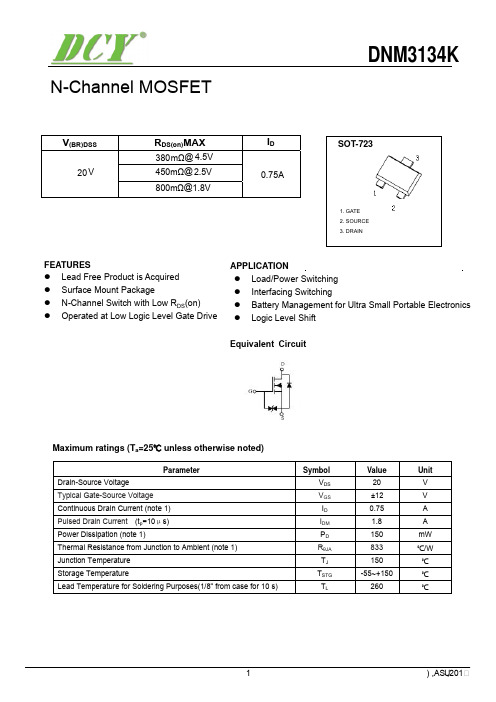
DNM3134K
V(BR)DSS
20 V
RDS(on)MAX
380mΩ@ 4.5V 450mΩ@ 2.5V
800mΩ@1.8V
ID
0.75A
SOT-723
1. GATE 2. SOURCE 3. DRAIN
FEATURES z Lead Free Product is Acquired z Surface Mount Package z N-Channel Switch with Low RDS(on) z Operated at Low Logic Level Gate Drive
3.0
2.5
T =25℃ a
T =100℃ a
2.0
1.5
1.0
0.5
0.0
0
1
2
3
4
GATE TO SOURCE VOLTAGE V (V) GS
(m)
DS(ON)
ON-RESISTANCE R
500
T =25℃ a
Pulsed
450
400
R DS(ON)
——
I
D
V =1.8V GS
350
V =2.5V GS
IGSS
Gate threshold voltage (note 2)
VGS(th)
Drain-source on-resistance (note 2)
RDS (on)
Forward transconductance (note 2)
gFS
Diode forward voltage
VSD
DYNAMIC CHARACTERISTICS (note 4)
人民电器 RS0、RS3系列半导体设备保护用熔断体 产品说明书
□ +40-5 围空气温度24小时内的平均值不超过+35℃,一年内测得的平均值应低于该值;□ 海拔:安装地点的海拔高度不超过2000m ;□ 大气条件:它的相对湿度在周围空气温度最高为40℃时不超过50%。
在较低温度下可以有较高的相对湿度,例如,在20℃下,相对湿度可达90%。
在这此条件下,由于温度变化,考虑到因温度变化发生在产品表面上的中等凝露;□ 电压:系统电压的最大值不超过熔断器额定电压的110%;□ 安装类别:本系列熔断器的安装类别为III 级;□ 污染等级:本系列熔断器的耐污秽等级不低于3级;□ 安装方位:RS0、RS3系列熔断体属B 型螺栓连接熔断体系统,直接用螺栓串接在电路中。
注:若熔断器在不同于正常安装规定条件下使用,应与制造厂协商。
周围空气温度:周围空气温度上限值不超过℃;周围空气温度下限值不低于℃;周正常工作条件及安装条件本系列熔断体的分断范围为“使用类别为。
即:半导体设备短路保护用熔断体。
a ,R ”“”分断范围与使用类别产品概述RS0、RS3系列半导体设备保护用熔断体适用于交流50Hz ,额定电压最高至500V ,额定电流至1000A 的工业电气配电装置中,主要作为硅整流、晶闸管的快速保护用。
产品符合:标准GB/T 13539.4 IEC 60269-4标准。
选型指南快速熔断器额定电流选择:Ie=Kd×IdmaxIe:快速熔断器额定电流;Kd:硅整流或晶闸管的保护系数;Idmax:流过硅整流器件的最大整流电流或者流过晶闸管的最大电流。
171172熔断体外形及安装尺寸a.RS0/RS3-50b.RS0/RS3-100~1000RS0系列熔断体技术参数RS3系列熔断体技术参数表1表2结构特征主要技术数据外形及安装尺寸本系列熔断体由型母线接线端子、熔管、熔体、填料、指示件组成。
由纯银片制成的变截面熔体封装于高强度的熔管内,熔管中填满高纯度石英砂作为灭弧介质,熔体二端采用点焊与母线接线端子牢固连接,指示件与熔体并联,当熔体熔断瞬间指示件立即弹出,显示熔断体已熔断。
AO3400 SOT-23-3L NMOS Vds30V 规格书AO推荐

ID(A)
15
VDS=5V 12
9
6
125°C 3
25°C
0
0
0.5
1
1.5
2
2.5
3
VGS(Volts) Figure 2: Transfer Characteristics (Note E)
Normalized On-Resistance
RDS(ON) (mΩ)
30
25 VGS=4.5V
20
15
Symbol
Parameter
Conditions
Min Typ Max Units
STATIC PARAMETERS
BVDSS Drain-Source Breakdown Voltage
ID=250µA, VGS=0V
30
V
IDSS
Zero Gate Voltage Drain Current
VDS=30V, VGS=0V
Parameter
Symbol
Drain-Source Voltage
VDS
Gate-Source Voltage
VGS
Continuous Drain Current
TA=25°C TA=70°C
ID
Pulsed Drain Current C
IDM
TA=25°C Power Dissipation B TA=70°C
(Note E)
IS (A)
1.0E+01
1.0E+00
40
1.0E-01
1.0E-02
1.0E-03
125°C
25°C
1.0E-04
1.0E-05
赛米控丹佛斯 配置IGBT M7芯片 SEMITRANS 3 SKM600GB12M7 数据表
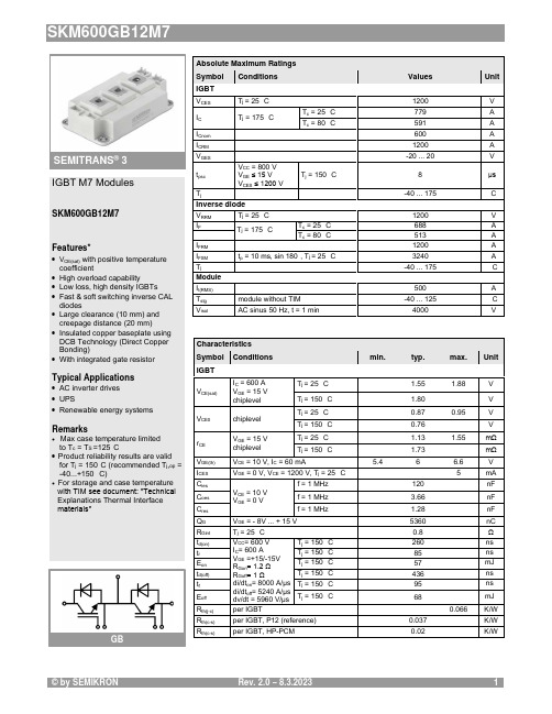
Absolute Maximum Ratings Symbol Conditions Values UnitIGBT V CES T j = 25 °C 1200 V I C T j = 175 °CT c = 25 °C 779 A T c = 80 °C591 A I Cnom 600 A I CRM1200 A V GES -20 (20)V t psc V CC = 800 V V GE ≤ 15 V V CES ≤ 1200 VT j = 150 °C8 μs T j-40 (175)°C Inverse diode V RRM T j = 25 °C 1200V I FT j = 175 °CT c = 25 °C 688A T c = 80 °C513 A I FRM 1200A I FSM t p = 10 ms, sin 180°, T j = 25 °C3240A T j-40 ... 175°C Module I t(RMS)500 A T stg module without TIM-40 ... 125 °C V isolAC sinus 50 Hz, t = 1 min4000VCharacteristics Symbol Conditions min. typ. max. UnitIGBT V CE(sat)I C = 600 A V GE = 15 V chiplevel T j = 25 °C 1.55 1.88V T j = 150 °C 1.80 V V CE0chiplevel T j = 25 °C 0.87 0.95 V T j = 150 °C 0.76 V r CE V GE = 15 V chiplevelT j = 25 °C 1.13 1.55 mΩ T j = 150 °C1.73 mΩ V GE(th)V CE = 10 V, I C = 60 mA5.46 6.6 V I CES V GE = 0 V, V CE = 1200 V, T j = 25 °C5 mA C ies V CE = 10 V V GE = 0 Vf = 1 MHz120 nF C oes f = 1 MHz 3.66 nF C res f = 1 MHz1.28 nF Q G V GE = - 8V ... + 15 V 5360 nC R Gint T j = 25 °C 0.8 Ω t d(on)V CC = 600 V I C = 600 AV GE =+15/-15V R Gon = 1.2 Ω R Goff = 1 Ωdi/dt on = 8000 A/µs di/dt off = 5240 A/µs dv/dt = 5960 V/µs T j = 150 °C 260 ns t r T j = 150 °C 85 ns E on T j = 150 °C 57 mJ t d(off)T j = 150 °C 436 ns t f T j = 150 °C 95 ns E off T j = 150 °C68mJ R th(j-c)per IGBT0.066K/W R th(c-s)per IGBT, P12 (reference)0.037 K/W R th(c-s)per IGBT, HP-PCM0.02K/WIGBT M7 ModulesSKM600GB12M7Features*∙V CE(sat) with positive temperature coefficient∙ High overload capability∙ Low loss, high density IGBTs ∙ Fast & soft switching inverse CAL diodes∙ Large clearance (10 mm) and creepage distance (20 mm)∙ Insulated copper baseplate using DCB Technology (Direct Copper Bonding)∙ With integrated gate resistorTypical Applications∙ AC inverter drives ∙ UPS∙ Renewable energy systemsRemarks∙Max case temperature limited to T c = T S =125°C∙ Product reliability results are valid for T j = 150°C (recommended T j ,op = -40...+150 °C)∙For storage and case temperature with TIM see document: ″Technical Explanations Thermal Interface materials″GBSEMITRANS ® 3Characteristics Symbol Conditions min. typ. max. UnitInverse diode V F = V EC I F = 600 A V GE = 0 V chiplevel T j = 25 °C 2.14 2.46V T j = 150 °C 2.07 V V F0chiplevel T j = 25 °C 1.30 1.50 V T j = 150 °C 0.90 V r F chiplevelT j = 25 °C 1.40 1.60 mΩ T j = 150 °C1.95 mΩ I RRM V CC = 600 V I F = 600 AV GE = -15 Vdi/dt off = 8000 A/µs T j = 150 °C 555 A Q rr T j = 150 °C92 µC E rr T j = 150 °C 43mJ R th(j-c)per diode0.09K/W R th(c-s)per diode, P12 (reference) 0.038 K/W R th(c-s)per diode, HP-PCM0.021 K/W Module L CE 15nH R CC'+EE'measured per switchT j = 25 °C 0.55mΩ T j = 150 °C0.85 mΩ R th(c-s)1calculated without thermal coupling, P12 (reference)0.0093 K/W R th(c-s)2including thermal coupling,T s underneath module, P12 (reference)0.015 K/W R th(c-s)2including thermal coupling,T s underneath module, HP-PCM 0.0078K/W M s to heat sink M635 Nm M t to terminal M52.55 Nm -Nm w325 gSEMITRANS ® 3 IGBT M7 ModulesSKM600GB12M7Features*∙V CE(sat) with positive temperature coefficient∙ High overload capability∙ Low loss, high density IGBTs ∙ Fast & soft switching inverse CAL diodes∙ Large clearance (10 mm) and creepage distance (20 mm)∙ Insulated copper baseplate using DCB Technology (Direct Copper Bonding)∙ With integrated gate resistorTypical Applications∙ AC inverter drives ∙ UPS∙ Renewable energy systemsRemarks∙Max case temperature limited to T c = T S =125°C∙ Product reliability results are valid for T j = 150°C (recommended T j ,op = -40...+150 °C)∙For storage and case temperature with TIM see document: ″Technical Explanations Thermal Interface materials″GBFig. 1: Typ. output characteristic, inclusive R CC'+ EE'Fig. 2: Rated current vs. temperature I C = f (T C )Fig. 3: Typ. turn-on /-off energy = f (I C ) Fig. 4: Typ. turn-on /-off energy = f (R G )Fig. 5: Typ. transfer characteristic Fig. 6: Typ. gate charge characteristicFig. 7: Typ. switching times vs. I C Fig. 8: Typ. switching times vs. gate resistor R GFig. 9: Transient thermal impedance Fig. 10: Typ. CAL diode forward charact., incl. R CC'+ EE'Fig. 11: CAL diode peak reverse recovery current Fig. 12: Typ. CAL diode peak reverse recovery chargePinout and DimensionsGBThis is an electrostatic discharge sensitive device (ESDS) according to international standard IEC 61340.*IMPORTANT INFORMATION AND WARNINGSThe specifications of SEMIKRON products may not be considered as any guarantee or assurance of product characteristics ("Beschaffenheitsgarantie"). The specifications of SEMIKRON products describe only the usual characteristics of SEMIKRON products to be expected in typical applications, which may still vary depending on the specific application. Therefore, products must be tested for the respective application in advance. Resulting from this, application adjustments of any kind may be necessary. Any user of SEMIKRON products is responsible for the safety of their applications embedding SEMIKRON products and must take adequate safety measures to prevent the applications from causing any physical injury, fire or other problem, also if any SEMIKRON product becomes faulty. Any user is responsible for making sure that the application design and realization are compliant with all laws, regulations, norms and standards applicable to the scope of application. Unless otherwise explicitly approved by SEMIKRON in a written document signed by authorized representatives of SEMIKRON, SEMIKRON products may not be used in any applications where a failure of the product or any consequences of the use thereof can reasonably be expected to result in personal injury. No representation or warranty is given and no liability is assumed with respect to the accuracy, completeness and/or use of any information herein, including without limitation, warranties of non-infringement of intellectual property rights of any third party. SEMIKRON does not convey any license under its or a third party’s patent rights, copyrights, trade secrets or other intellectual property rights, neither does it make any representation or warranty of non-infringement of intellectual property rights of any third party which may arise from a user’s applications. Due to technical requirements our products may contain dangerous substances. For information on the types in question please contact the nearest SEMIKRON sales office. This document supersedes and replaces all previous SEMIKRON information of comparable content and scope. SEMIKRON may update and/or revise this document at any time.。
rs3m二极管参数
rs3m二极管参数
RS3M是一种二极管,其参数主要包括电流-电压特性、频率响应、温度特性、电容和开启速度等。
电流-电压特性是指二极管的导通和截止特性。
RS3M是一种正向导通的双向二极管,通常用于保护电路免受过电压和反向电流的影响。
其正向导通压降一般在0.6V以下,可根据运行电流选择合适的二极管。
频率响应是指二极管对于交流信号的响应能力。
RS3M是一种快速恢复二极管(Fast Recovery Diode),其恢复速度较快,适用于高频率应用。
常见的恢复时间为150纳秒,频率达到几十兆赫兹。
温度特性是指二极管在不同温度下的电性能变化。
RS3M的温度系数较小,在工作温度范围内变化不大,具有较好的温度稳定性。
其典型温度系数为0.1%/℃。
电容是指二极管的内部电容。
RS3M的内部电容较小,一般在几十皮法级别。
这使得其适用于高速开关和快速切换电路,减少了开关过程中的能量损失。
开启速度是指二极管从截止状态到导通状态的时间。
RS3M是一种快速恢复二极管,具有较快的开启速度。
其快速恢复特性使得它能够在高频率开关应用中实现快速开关和恢复。
总结起来,RS3M二极管具有低导通压降、快速恢复、较小的温度系数和内部电容等特点。
它适用于高频率开关和快速切换电路,能够快速、稳定地进行电流和电压的变化,保护电路免受过压和反向电流的影响。
- 1、下载文档前请自行甄别文档内容的完整性,平台不提供额外的编辑、内容补充、找答案等附加服务。
- 2、"仅部分预览"的文档,不可在线预览部分如存在完整性等问题,可反馈申请退款(可完整预览的文档不适用该条件!)。
- 3、如文档侵犯您的权益,请联系客服反馈,我们会尽快为您处理(人工客服工作时间:9:00-18:30)。
RSM002P03 Pch -30V -200mA Small Signal MOSFETDatasheetl OutlineV DSS -30VSOT-723 R DS(on)(Max.)1.4Ω SC-105AA I D ±200mA VMT3P D150mWl Inner circuitlFeatures1) Low on-resistance.2) Small package (VMT3)3) 4V drive.4) Lead Free/RoHS Compliant.l Packaging specificationsType PackingEmbossed Tape Reel size (mm)180l ApplicationTape width (mm)8SwitchingBasic ordering unit (pcs)8000 Taping code T2L MarkingWP l Absolute maximum ratings (T a = 25°C ,unless otherwise specified)ParameterSymbol Value Unit Drain - Source voltageV DSS -30V Continuous drain current I D ±200mA Pulsed drain current I DP *1±400mA Gate - Source voltage V GSS ±20V Power dissipation P D *2150mWJunction temperatureT j 150℃Operating junction and storage temperature rangeT stg-55 to +150℃RSM002P03 Datasheet l Thermal resistance Parameter SymbolValuesUnit Min.Typ.Max.Thermal resistance, junction - ambient R thJA*2--833℃/W l Electrical characteristics (T a = 25°C)Parameter Symbol ConditionsValuesUnit Min.Typ.Max.Drain - Source breakdownvoltageV(BR)DSS V GS = 0V, I D = -1mA-30--VBreakdown voltage temperature coefficient ΔV(BR)DSS I D = -1mA--20.7-mV/℃ ΔT j referenced to 25℃Zero gate voltagedrain currentI DSS V DS = -30V, V GS = 0V---1μA Gate - Source leakage current I GSS V GS = ±20V, V DS = 0V--±10μA Gate threshold voltage V GS(th) V DS = -10V, I D = -1mA-1.0--2.5VGate threshold voltage temperature coefficient ΔV GS(th) I D = -1mA- 3.1-mV/℃ ΔT j referenced to 25℃Static drain - source on - state resistance R DS(on)*3V GS = -10V, I D = -200mA-0.9 1.4Ω V GS = -4.5V, I D = -150mA- 1.4 2.1V GS = -4.0V, I D = -150mA- 1.6 2.4Forward TransferAdmittance|Y fs|*3 V DS = -10V, I D = -150mA200--mS*1 Pw ≤ 10μs, Duty cycle ≤ 1%*2 Each teminal mounted on a recommended land*3 PulsedRSM002P03Datasheetl Electrical characteristics (T a = 25°C)ParameterSymbol Conditions Values UnitMin.Typ.Max.Input capacitance C iss V GS = 0V -30-pFOutput capacitance C oss V DS = -10V -4-Reverse transfer capacitance C rss f = 1MHz-5-Turn - on delay time t d(on)*3 V DD ⋍ -15V,V GS = -10V-8-nsRise time t r *3 I D = -150mA -5-Turn - off delay time t d(off)*3 R L ⋍ 100Ω-30-Fall timet f *3R G = 10Ω-40-l Body diode electrical characteristics (Source-Drain) (T a = 25°C)ParameterSymbol ConditionsValues Unit Min.Typ.Max.Continuous forward current I S T a = 25℃--125mA Pulse forward current I SP --400mA Forward voltageV SD *3V GS = 0V, I S = -100mA---1.2VFig.1 Power Dissipation Derating Curve Fig.2 Drain Current Derating CurveFig.3 Typical Output Characteristics(I)Fig.4 Typical Output Characteristics(II)Fig.5 Breakdown Voltage vs. Junction TemperatureFig.6 Typical Transfer CharacteristicsFig.7 Gate Threshold Voltage vs. Junction Temperature Fig.8 Forward Transfer Admittance vs. Drain CurrentFig.9 Static Drain - Source On - State Resistance vs. Gate Source Voltage Fig.10 Static Drain - Source On - State Resistance vs. Junction TemperatureFig.11 Static Drain - Source On - State Resistance vs. Drain Current (I)Fig.12 Static Drain - Source On - State Resistance vs. Drain Current (lI)Fig.13 Static Drain - Source On - State Resistance vs. Drain Current (Ill)Fig.14 Static Drain - Source On - State Resistance vs. Drain Current (lV)Fig.15 Typical Capacitance vs.Fig.16 Switching Characteristics Drain - Source VoltageFig.17 Source Current vs. Source Drain Voltagel Measurement circuitsFig.1-1 Switching Time Measurement Circuit Fig.1-2 Switching Waveformsl NoticeThis product might cause chip aging and breakdown under the large electrified environment.Please consider to design ESD protection circuit.RSM002P03 Datasheet l DimensionsNoticePrecaution on using ROHM Products1. Our Products are designed and manufactured for application in ordinary electronic equipments (such as AV equipment,OA equipment, telecommunication equipment, home electronic appliances, amusement equipment, etc.). If you intend to use our Products in devices requiring extremely high reliability (such as medical equipment (Note 1), transport equipment, traffic equipment, aircraft/spacecraft, nuclear power controllers, fuel controllers, car equipment including car accessories, safety devices, etc.) and whose malfunction or failure may cause loss of human life, bodily injury or serious damage to property (“Specific Applications”), please consult with the ROHM sales representative in advance.Unless otherwise agreed in writing by ROHM in advance, ROHM shall not be in any way responsible or liable for any damages, expenses or losses incurred by you or third parties arising from the use of any ROHM’s Products for Specific Applications.2. ROHM designs and manufactures its Products subject to strict quality control system. However, semiconductorproducts can fail or malfunction at a certain rate. Please be sure to implement, at your own responsibilities, adequate safety measures including but not limited to fail-safe design against the physical injury, damage to any property, whicha failure or malfunction of our Products may cause. The following are examples of safety measures:[a] Installation of protection circuits or other protective devices to improve system safety[b] Installation of redundant circuits to reduce the impact of single or multiple circuit failure3. Our Products are designed and manufactured for use under standard conditions and not under any special orextraordinary environments or conditions, as exemplified below. Accordingly, ROHM shall not be in any way responsible or liable for any damages, expenses or losses arising from the use of any ROHM’s Products under any special or extraordinary environments or conditions. If you intend to use our Products under any special or extraordinary environments or conditions (as exemplified below), your independent verification and confirmation of product performance, reliability, etc, prior to use, must be necessary:[a] Use of our Products in any types of liquid, including water, oils, chemicals, and organic solvents[b] Use of our Products outdoors or in places where the Products are exposed to direct sunlight or dust[c] Use of our Products in places where the Products are exposed to sea wind or corrosive gases, including Cl2,H2S, NH3, SO2, and NO2[d] Use of our Products in places where the Products are exposed to static electricity or electromagnetic waves[e] Use of our Products in proximity to heat-producing components, plastic cords, or other flammable items[f] Sealing or coating our Products with resin or other coating materials[g] Use of our Products without cleaning residue of flux (even if you use no-clean type fluxes, cleaning residue offlux is recommended); or Washing our Products by using water or water-soluble cleaning agents for cleaningresidue after soldering[h] Use of the Products in places subject to dew condensation4. The Products are not subject to radiation-proof design.5. Please verify and confirm characteristics of the final or mounted products in using the Products.6. In particular, if a transient load (a large amount of load applied in a short period of time, such as pulse. is applied,confirmation of performance characteristics after on-board mounting is strongly recommended. Avoid applying power exceeding normal rated power; exceeding the power rating under steady-state loading condition may negatively affect product performance and reliability.7. De-rate Power Dissipation depending on ambient temperature. When used in sealed area, confirm that it is the use inthe range that does not exceed the maximum junction temperature.8. Confirm that operation temperature is within the specified range described in the product specification.9. ROHM shall not be in any way responsible or liable for failure induced under deviant condition from what is defined inthis document.Precaution for Mounting / Circuit board design1. When a highly active halogenous (chlorine, bromine, etc.) flux is used, the residue of flux may negatively affect productperformance and reliability.2. In principle, the reflow soldering method must be used on a surface-mount products, the flow soldering method mustbe used on a through hole mount products. If the flow soldering method is preferred on a surface-mount products, please consult with the ROHM representative in advance.For details, please refer to ROHM Mounting specificationPrecautions Regarding Application Examples and External Circuits1. If change is made to the constant of an external circuit, please allow a sufficient margin considering variations of thecharacteristics of the Products and external components, including transient characteristics, as well as static characteristics.2. You agree that application notes, reference designs, and associated data and information contained in this documentare presented only as guidance for Products use. Therefore, in case you use such information, you are solely responsible for it and you must exercise your own independent verification and judgment in the use of such information contained in this document. ROHM shall not be in any way responsible or liable for any damages, expenses or losses incurred by you or third parties arising from the use of such information.Precaution for ElectrostaticThis Product is electrostatic sensitive product, which may be damaged due to electrostatic discharge. Please take proper caution in your manufacturing process and storage so that voltage exceeding the Products maximum rating will not be applied to Products. Please take special care under dry condition (e.g. Grounding of human body / equipment / solder iron, isolation from charged objects, setting of Ionizer, friction prevention and temperature / humidity control).Precaution for Storage / Transportation1. Product performance and soldered connections may deteriorate if the Products are stored in the places where:[a] the Products are exposed to sea winds or corrosive gases, including Cl2, H2S, NH3, SO2, and NO2[b] the temperature or humidity exceeds those recommended by ROHM[c] the Products are exposed to direct sunshine or condensation[d] the Products are exposed to high Electrostatic2. Even under ROHM recommended storage condition, solderability of products out of recommended storage time periodmay be degraded. It is strongly recommended to confirm solderability before using Products of which storage time is exceeding the recommended storage time period.3. Store / transport cartons in the correct direction, which is indicated on a carton with a symbol. Otherwise bent leadsmay occur due to excessive stress applied when dropping of a carton.4. Use Products within the specified time after opening a humidity barrier bag. Baking is required before using Products ofwhich storage time is exceeding the recommended storage time period.Precaution for Product LabelA two-dimensional barcode printed on ROHM Products label is for ROHM’s internal use only.Precaution for DispositionWhen disposing Products please dispose them properly using an authorized industry waste company.Precaution for Foreign Exchange and Foreign Trade actSince concerned goods might be fallen under listed items of export control prescribed by Foreign exchange and Foreign trade act, please consult with ROHM in case of export.Precaution Regarding Intellectual Property Rights1. All information and data including but not limited to application example contained in this document is for referenceonly. ROHM does not warrant that foregoing information or data will not infringe any intellectual property rights or any other rights of any third party regarding such information or data.2. ROHM shall not have any obligations where the claims, actions or demands arising from the combination of theProducts with other articles such as components, circuits, systems or external equipment (including software).3. No license, expressly or implied, is granted hereby under any intellectual property rights or other rights of ROHM or anythird parties with respect to the Products or the information contained in this document. Provided, however, that ROHM will not assert its intellectual property rights or other rights against you or your customers to the extent necessary to manufacture or sell products containing the Products, subject to the terms and conditions herein.Other Precaution1. This document may not be reprinted or reproduced, in whole or in part, without prior written consent of ROHM.2. The Products may not be disassembled, converted, modified, reproduced or otherwise changed without prior writtenconsent of ROHM.3. In no event shall you use in any way whatsoever the Products and the related technical information contained in theProducts or this document for any military purposes, including but not limited to, the development of mass-destruction weapons.4. The proper names of companies or products described in this document are trademarks or registered trademarks ofROHM, its affiliated companies or third parties.DatasheetPart NumberRSM002P03PackageVMT3Unit Quantity8000Minimum Package Quantity 8000Packing TypeTaping Constitution Materials Listinquiry RoHSYes RSM002P03 - Web Page Distribution InventoryBuy。