MB2S 封装MBS 系列规格书推荐
MB8S 封装MBS 系列规格书推荐

0
1
1.0
1
10 VR, REVERSE VOLTAGE (V)
100
NUMBER OF CYCLES AT 60 Hz
FIG.5 TYPICAL REVERSE CHRACTERISTICS
INVSTANTANEOUS REVERSE CURRENT (µA)
10 00
100
T J= 125 C
O
.008(0.20) MAX
.083(2.12) .043(1.10)
Dimensions in inches and (millimeters)
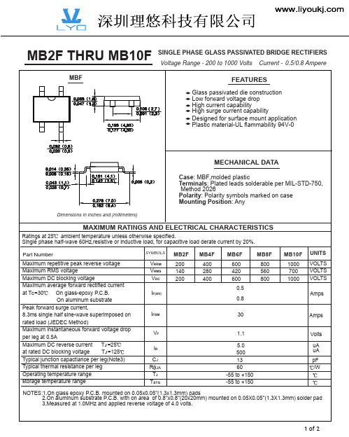
MAXIMUM RATINGS AND ELECTRICAL CHARACTERISTICS
Ratings at 25 ambient temperature unless otherwise specified. Single phase half-wave 60Hz,resistive or inductive load, for capacitive load derate current by 20%. Part Number Maximum repetitive peak reverse voltage Maximum RMS voltage Maximum DC blocking voltage Maximum average forward rectified current at TC=30 On glass-epoxy P.C.B. On aluminum substrate Peak forward surge current, 8.3ms single half sine-wave superimposed on rated load (JEDEC Method) Maximum instantaneous forward voltage drop per leg at 0.4A Maximum DC reverse current TA=25 at rated DC blocking voltage TA=125 Typical junction capactiance per leg(Note3) Typical thermal resistance per leg Operating temperature range storage temperature range
超快恢复二极管 ES2M SMB(DO-214AA)系列规格书推荐

CCLeoaamsdepFlMiareanette.FrSiianelis:ehMo/RordoldehersidnCgPoilnmafsoptrliimca.natti(oUNnLo) tFel1a)m("mPa"Sbuiliftfyix designates
VRMS 35 70 105 140 210 280 420 560 700
Maximum DC blocking voltage
VDC 50 100 150 200 300 400 600 800 1000
Maximum average forward rectified current
I(AV)
MAX 2.95 2.25 .20 .51 1.40 2.32 5.69 4.57 3.94
NOTE
MECHANICAL DATA
Case: JEDEC DO-214AA molded plastic body over passivated chip Terminals: Solder plated, solderable per MIL-STD-750, Method 2026 Polarity: Color band denotes cathode end Mounting Position: Any Weight :0.005 ounce, 0.138 grams
Cycles
Peak Forward Surge Current - Amperesversus Number Of Cycles At 60Hz - Cycles
Figure 5 New SMB Assembly
Round Lead Process
Figure 6 Reverse Recovery Time Characteristic And Test Circuit Diagram
LED芯片知识-MB、GB、TS、AS芯片定义与特点

LED芯片知识-MB、GB、TS、AS芯片定义与特点一、MB 芯片定义与特点定义﹑M B芯片﹑M e t a l Bonding (金属粘着)芯片﹑该芯片属于UEC 的专利产品。
特点﹑1: 采用高散热系数的材料---Si 作为衬底、散热容易。
2﹑通过金属层来接合(wafer bonding)磊晶层和衬底,同时反射光子,避免衬底的吸收。
3:导电的Si 衬底取代GaAs 衬底,具备良好的热传导能力(导热系数相差3~4 倍),更适应于高驱动电流领域。
4:底部金属反射层、有利于光度的提升及散热5:尺寸可加大、应用于High power 领域、eg : 42mil MB 二、GB 芯片定义和特点定义﹑GB芯片﹑Glue Bonding (粘着结合)芯片﹑该芯片属于UEC 的专利产品特点﹑1﹑透明的蓝宝石衬底取代吸光的GaAs 衬底、其出光功率是传统AS (Absorbable structure)芯片的2 倍以上、蓝宝石衬底类似TS 芯片的GaP 衬底。
2﹑芯片四面发光、具有出色的Pattern 3﹑亮度方面、其整体亮度已超过TS 芯片的水准(8.6mil) 4﹑双电极结构、其耐高电流方面要稍差于TS 单电极芯片三、TS 芯片定义和特点定义﹑TS芯片﹑transparent structure(透明衬底)芯片、该芯片属于HP 的专利产品。
特点﹑1.芯片工艺制作复杂、远高于AS led 2. 信赖性卓越3.透明的GaP 衬底、不吸收光、亮度高 4.应用广泛四、AS 芯片定义和特点定义﹑A S芯片﹑A bso rba ble structure(吸收衬底)芯片﹑经过近四十年的发展努力、台湾LED 光电业界对于该类型芯片的研发﹑生产﹑销售处于成熟的阶段、各大公司在此方面的研发水平基本处于同一水准、差距不大. 大陆芯片制造业起步较晚、其亮度及可靠度与台湾业界还有一定的差距、在这里我们所谈的AS 芯片、特指UEC 的AS 芯片、eg: 712SOL-VR, 709SOL-VR, 712SYM-VR,709SYM-VR 等特点﹑1. 四元芯片、采用MOVPE 工艺制备、亮度相对于常规芯片要亮 2. 信赖性优良 3.应用广泛tips:感谢大家的阅读,本文由我司收集整编。
贴片二极管封装类型尺寸

贴片二极管封装类型尺寸1. 引言贴片二极管是一种常用的电子元件,用于电子电路中的整流、开关等功能。
封装是贴片二极管的外形结构,不同的封装类型和尺寸适用于不同的应用场景。
本文将介绍贴片二极管的封装类型和尺寸,以便读者更好地了解和选择适合自己项目的贴片二极管。
2. 贴片二极管封装类型贴片二极管的封装类型主要有以下几种:2.1. SMA封装SMA封装是一种表面贴装封装,其尺寸较小,适用于空间受限的应用场景。
SMA封装的尺寸为2.0mm x 1.25mm,高度约为1.1mm,常见的型号有SMA(0201)。
2.2. SMB封装SMB封装是一种中等尺寸的表面贴装封装,适用于一般的电子电路设计。
SMB封装的尺寸为3.2mm x 1.6mm,高度约为1.1mm,常见的型号有SMB(0402)。
2.3. SMC封装SMC封装是一种较大尺寸的表面贴装封装,适用于功率较大的电子电路设计。
SMC 封装的尺寸为5.0mm x 2.5mm,高度约为1.5mm,常见的型号有SMC(0603)。
2.4. SOD-123封装SOD-123封装是一种小型的表面贴装封装,适用于空间受限的应用场景。
SOD-123封装的尺寸为2.6mm x 1.8mm,高度约为1.1mm,常见的型号有SOD-123。
2.5. SOD-323封装SOD-323封装是一种较小尺寸的表面贴装封装,适用于空间受限的应用场景。
SOD-323封装的尺寸为1.6mm x 0.8mm,高度约为0.8mm,常见的型号有SOD-323。
3. 贴片二极管封装尺寸对比下表列出了常见的贴片二极管封装类型和尺寸的对比:封装类型尺寸适用场景SMA(0201) 2.0mm x 1.25mm 空间受限的应用场景SMB(0402) 3.2mm x 1.6mm 一般电子电路设计封装类型尺寸适用场景SMC(0603) 5.0mm x 2.5mm 功率较大的电子电路设计SOD-123 2.6mm x 1.8mm 空间受限的应用场景SOD-323 1.6mm x 0.8mm 空间受限的应用场景4. 如何选择合适的贴片二极管封装类型选择合适的贴片二极管封装类型需要考虑以下几个因素:4.1. 应用场景首先需要根据应用场景确定是否对尺寸有特殊要求。
MEMORY存储芯片MAX232ESE中文规格书

MAX202E–MAX213E,MAX232E/MAX241E±15kV ESD-Protected, 5V RS-232 TransceiversGeneral DescriptionThe MAX202E-MAX213E, MAX232E, and MAX241E are a family of RS-232 and V.28 transceivers with high ±15kV ESD HBM protection and integrated charge pump circuit-ry for single +5V supply operation. The various combina-tions of features are outlined in the Selector Guide.The drivers and receivers for all ten devices meet all EIA/TIA-232E and CCITT V.28 specifications at data rates up to 120kbps when loaded.The MAX211E/MAX213E/MAX241E are available in 28-pin SO and SSOP packages. The MAX202E/MAX232E come in 16-pin TSSOP, narrow SO, wide SO, and DIP packages. The MAX203E comes in a 20-pin DIP/SO package, and needs no external charge-pump capaci-tors. The MAX205E comes in a 24-pin wide DIP pack-age, and also eliminates external charge-pump capacitors.Applications•Battery-Powered Equipment •Hand-Held Equipment•Portable Diagnostics EquipmentBenefits and Features•Saves Board Space•Integrated High ±15kV HBM ESD Protection •Integrated Charge Pump CircuitryEliminates the Need for a Bipolar ±12V SupplyEnables Single Supply Operation From +5V Supply •Integrated 0.1µF Capacitors (MAX203E, MAX205E)•24 pin SSOP Package Saves up to 40% Versus SO Package•Saves Power for Reduced Power Requirements •1µA Shutdown Mode•15µA Shutdown Mode for MAX213EPin Configurations and Typical Operating Circuits appear at end of data sheet.YesPARTNO. OF RS-232DRIVERSNO. OF RS-232RECEIVERSRECEIVERS ACTIVE IN SHUTDOWNNO. OF EXTERNALCAPACITORS(µF)LOW-POWER SHUTDOWNTTL TRI-STATE MAX202E 220 4 (0.1)No No MAX203E 220None No No MAX205E 550None Yes Yes MAX206E 430 4 (0.1)Yes Yes MAX207E 530 4 (0.1)No No MAX208E 440 4 (0.1)No No MAX211E 450 4 (0.1)Yes Yes MAX213E 452 4 (0.1)Yes Yes MAX232E 220 4 (1)No No MAX241E454 (1)YesAutoShutdown and UCSP are trademarks of Maxim Integrated Products, Inc.Ordering InformationOrdering Information continued at end of data sheet.Absolute Maximum RatingsV CC ..........................................................................-0.3V to +6V V+................................................................(V CC - 0.3V) to +14V V-............................................................................-14V to +0.3V Input VoltagesT_IN............................................................-0.3V to (V+ + 0.3V)R_IN...................................................................................±30V Output VoltagesT_OUT.................................................(V- - 0.3V) to (V+ + 0.3V)R_OUT......................................................-0.3V to (V CC + 0.3V)Short-Circuit Duration, T_OUT....................................Continuous Continuous Power Dissipation (T A = +70°C)16-Pin Plastic DIP (derate 10.53mW/°C above +70°C)....842mW 16-Pin Narrow SO (derate 8.70mW/°C above +70°C).....696mW 16-Pin Wide SO (derate 9.52mW/°C above +70°C)......762mW 16-Pin TSSOP (derate 9.4mW/°C above +70°C)...........755mW20-Pin Plastic DIP (derate 11.11mW/°C above +70°C)...889mW 20-Pin SO (derate 10.00mW/°C above +70°C).............800mW 24-Pin Narrow Plastic DIP(derate 13.33mW/°C above +70°C) ...............................1.07W 24-Pin Wide Plastic DIP(derate 14.29mW/°C above +70°C)................................1.14W 24-Pin SO (derate 11.76mW/°C above +70°C).............941mW 24-Pin SSOP (derate 8.00mW/°C above +70°C)..........640mW 28-Pin SO (derate 12.50mW/°C above +70°C)....................1W 28-Pin SSOP (derate 9.52mW/°C above +70°C)..........762mW Operating Temperature RangesMAX2_ _EC_ _.....................................................0°C to +70°C MAX2_ _EE_ _...................................................-40°C to +85°C Storage Temperature Range.............................-65°C to +165°C Lead Temperature (soldering, 10s).................................+300°CElectrical Characteristics(V CC = +5V ±10% for MAX202E/206E/208E/211E/213E/232E/241E; V CC = +5V ±5% for MAX203E/205E/207E; C1–C4 = 0.1µF for MAX202E/206E/207E/208E/211E/213E; C1–C4 = 1µF for MAX232E/241E; T A = T MIN to T MAX ; unless otherwise noted. Typical values are at T A = +25°C.)Stresses beyond those listed under “Absolute Maximum Ratings” may cause permanent damage to the device. These are stress ratings only, and functional operation of the device at these or any other conditions beyond those indicated in the operational sections of the specifications is not implied. Exposure to absolute maximum rating conditions for extended periods may affect device reliability.Electrical Characteristics (continued)(V CC= +5V ±10% for MAX202E/206E/208E/211E/213E/232E/241E; V CC= +5V ±5% for MAX203E/205E/207E; C1–C4 = 0.1µF for MAX202E/206E/207E/208E/211E/213E; C1–C4 = 1µF for MAX232E/241E; T A= T MIN to T MAX; unless otherwise noted. Typical valuesNote 1:MAX211EE_ _ tested with V CC= +5V ±5%.Typical Operating Characteristics。
MB2F-MB10F MBF 系列规格书推荐
IF, INSTANTANEOUS FORWARD CURRENT (A)
Fig. 2 Typical Forward Characteristics (per leg) 10
0.8
Al. Substrate PC Board
1.0
0.6
0.4
Glass Epoxy PC Board
0.1
0.2
IFSM, PEAK FORWARD SURGE CURRENT (A)
Fig. 3 Maximum Peak Forward Surge Current (per leg) 35 30
Cj, JUNCTION CAPACITANCE (pF)
100
Fig. 4 Typical Junction Capacitance
TJ = 25°C f = 1.0MHz
20
10
10
TA = 25°C Single Half Sine-Wave Pulse Width =8.3ms (JEDEC Method)
0
1
1.0
10 NUMBER OF CYCLES AT 60 Hz
1
10 VR, REVERSE VOLTAGE (V)
MB2F THRU MB10F
MBF
SINGLE PHASE GLASS PASSIVATED BRIDGE RECTIFIERS Voltage Range - 200 to 1000 Volts Current - 0.5/0.8 Ampere
FEATURES
Glass passivated die construction Low forward voltage drop High current capability High surge current capability Designed for surface mount application Plastic material-UL flammability 94V-0
MGate Series 发行说明说明书
MGate Manager for MGate Series Release NotesSupported Operating SystemsNotesChangesApplicable ProductsBugs Fixed• Supports cybersecurity features for the MGate MB3000 Series.• User parameter in GSD file PXC_06CC.gsd are incorrectly parsed for MGate 5101-PBM-MN/5102-PBM-PN.• User parameter in GSD file si04806a.gsd are incorrectly parsed for MGate 5101-PBM-MN/5102-PBM-PN.• GSD management failed to add SE100E2E.GSD for MGate 5101-PBM-MN/5102-PBM-PN.EnhancementsWindows 10, Windows 2000, Windows 7, Windows 8, Windows 8.1, Windows Server 2003, Windows Server 2008, Windows Server 2008 R2, Windows Server 2012, Windows Server 2012 R2, Windows Server 2016, Windows Server 2019, Windows Vista, Windows XPMGate MB3180, MGate MB3280, MGate MB3480, MGate MB3170, MGate MB3170I, MGate MB3270,MGate MB3270I, MGate MB3170-T, MGate MB3170I-T, MGate MB3270-T, MGate MB3270I-T, MGate MB3170-M-SC, MGate MB3170-M-ST, MGate MB3170-S-SC, MGate MB3170I-M-SC, MGate MB3170I-S-SC, MGate MB3170-M-SC-T, MGate MB3170-M-ST-T, MGate MB3170-S-SC-T, MGate MB3170I-M-SC-T, MGate MB3170I-S-SC-T, MGate 5101-PBM-MN, MGate 5101-PBM-MN-T, MGate 5105-MB-EIP, MGate 5105-MB-EIP-T, MGate 5102-PBM-PN, MGate 5102-PBM-PN-T, MGate EIP3170, MGate EIP3170I, MGate EIP3270, MGate EIP3270I, MGate EIP3170-T, MGate EIP3170I-T,MGate EIP3270-T, MGate 4101-MB-PBS, MGate 4101I-MB-PBS, MGate 4101-MB-PBS-T, MGate 4101I-MB-PBS-T• Added username login function for MGate MB3000 Series, MGate 5101-PBM-MN, MGate 5102-PBM-PN, and MGate 5105-MB-EIP.New FeaturesN/AN/ASupported Operating SystemsNotesChangesApplicable ProductsBugs Fixed• Supports cybersecurity features for MGate 5101-PBM-MN, MGate 5102-PBM-PN, and MGate 5105-MB-EIP.• Added EtherNet/IP encapsulation inactivity timeout and configuration instance settings for MGate 5105-MB-EIP.• MB3270 cannot be configured in high-latency network environments.EnhancementsWindows 10, Windows 2000, Windows 7, Windows 8, Windows 8.1, Windows Server 2003, Windows Server 2008, Windows Server 2008 R2, Windows Server 2012, Windows Server 2012 R2, Windows Server 2016, Windows Vista, Windows XPMGate MB3180, MGate MB3280, MGate MB3480, MGate MB3170, MGate MB3170I, MGate MB3270,MGate MB3270I, MGate MB3170-T, MGate MB3170I-T, MGate MB3270-T, MGate MB3270I-T, MGate MB3170-M-SC, MGate MB3170-M-ST, MGate MB3170-S-SC, MGate MB3170I-M-SC, MGate MB3170I-S-SC, MGate MB3170-M-SC-T, MGate MB3170-M-ST-T, MGate MB3170-S-SC-T, MGate MB3170I-M-SC-T, MGate MB3170I-S-SC-T, MGate 5101-PBM-MN, MGate 5101-PBM-MN-T, MGate 5105-MB-EIP, MGate 5105-MB-EIP-T, MGate 5102-PBM-PN, MGate 5102-PBM-PN-T, MGate EIP3170, MGate EIP3170I, MGate EIP3270, MGate EIP3270I, MGate EIP3170-T, MGate EIP3170I-T,MGate EIP3270-T, MGate 4101-MB-PBS, MGate 4101I-MB-PBS, MGate 4101-MB-PBS-T, MGate 4101I-MB-PBS-T• Supports Modbus fault protection function for MGate 5101-PBM-MN and MGate 5105-MB-EIP.• Supports EtherNet/IP fault protection function for MGate 5105-MB-EIP.• Supports accessible IP for MGate 5102-PBM-PN.New FeaturesN/AN/ASupported Operating SystemsNotesChangesApplicable ProductsBugs Fixed• MGate 5101-PBM-MN / 5102-PBM-PN cannot communicate with WAGO 750-303 due to incorrect parsing.• Supports EIP3000 Forward open connection path.• MGate 5101-PBM-MN/5102-PBM-PN cannot add SIE180BB.GSD (for Siemens SIMEAS P).• MGate 5101-PBM-MN/5102-PBM-PN cannot remove GSD file with read-only attribute.• MGate 5105-MB-EIP cannot be configured for some version.EnhancementsWindows 10, Windows 2000, Windows 7, Windows 8, Windows 8.1, Windows Server 2003, Windows Server 2008, Windows Server 2008 R2, Windows Server 2012, Windows Server 2012 R2, Windows Vista, Windows XPMGate MB3280, MGate MB3180, MGate MB3480, MGate MB3170, MGate MB3170I, MGate MB3270,MGate MB3270I, MGate MB3170-T, MGate MB3170I-T, MGate MB3270-T, MGate MB3270I-T, MGate MB3170-M-SC, MGate MB3170-M-ST, MGate MB3170-S-SC, MGate MB3170I-M-SC, MGate MB3170I-S-SC, MGate MB3170-M-SC-T, MGate MB3170-M-ST-T, MGate MB3170-S-SC-T, MGate MB3170I-M-SC-T, MGate MB3170I-S-SC-T, MGate 5101-PBM-MN, MGate 5101-PBM-MN-T, MGate 5105-MB-EIP, MGate 5105-MB-EIP-T, MGate 5102-PBM-PN, MGate 5102-PBM-PN-T, MGate EIP3170, MGate EIP3170I, MGate EIP3270, MGate EIP3270I, MGate EIP3170-T, MGate EIP3170I-T,MGate EIP3270-T, MGate 4101-MB-PBS, MGate 4101I-MB-PBS, MGate 4101-MB-PBS-T, MGate 4101I-MB-PBS-T• Supports auto device routing for MGate MB3270, MB3280, and MB3480 Series.New FeaturesN/AN/ASupported Operating SystemsNotesChangesApplicable ProductsBugs Fixed• Modified the MG4101 I/O mapping page, dynamic GSD export, and I/O data view.• Supports MB3180 Web Console.• Added MB3000 Modbus TCP listen port setting.• Multi-language support.• MGate manager does not modify broadcast IP after changing IP and netmask settings for MGate 5101/5102/5105 devices.• Updated the PNIO version of MGate 5102 GSDML.EnhancementsWindows 10, Windows 2000, Windows 7, Windows 8, Windows 8.1, Windows Server 2003, Windows Server 2008, Windows Server 2008 R2, Windows Server 2012, Windows Server 2012 R2, Windows Vista, Windows XPMGate MB3180, MGate MB3280, MGate MB3480, MGate MB3170, MGate MB3170I, MGate MB3270,MGate MB3270I, MGate MB3170-T, MGate MB3170I-T, MGate MB3270-T, MGate MB3270I-T, MGate MB3170-M-SC, MGate MB3170-M-ST, MGate MB3170-S-SC, MGate MB3170I-M-SC, MGate MB3170I-S-SC, MGate MB3170-M-SC-T, MGate MB3170-M-ST-T, MGate MB3170-S-SC-T, MGate MB3170I-M-SC-T, MGate MB3170I-S-SC-T, MGate 5101-PBM-MN, MGate 5101-PBM-MN-T, MGate 5105-MB-EIP, MGate 5105-MB-EIP-T, MGate 5102-PBM-PN, MGate 5102-PBM-PN-T, MGate EIP3170, MGate EIP3170I, MGate EIP3270, MGate EIP3270I, MGate EIP3170-T, MGate EIP3170I-T,MGate EIP3270-T, MGate 4101-MB-PBS, MGate 4101I-MB-PBS, MGate 4101-MB-PBS-T, MGate 4101I-MB-PBS-T• Supports Windows 10.• MGate 4101 Modbus Fault Protection setting.New FeaturesN/AN/ASupported Operating SystemsNotesChangesApplicable ProductsBugs FixedN/AN/AEnhancementsWindows 2000, Windows 7, Windows 8, Windows 8.1, Windows Server 2003, Windows Server 2008,Windows Server 2008 R2, Windows Server 2012, Windows Server 2012 R2, Windows Vista, Windows XPMGate MB3180, MGate MB3280, MGate MB3480, MGate MB3170, MGate MB3170I, MGate MB3270,MGate MB3270I, MGate MB3170-T, MGate MB3170I-T, MGate MB3270-T, MGate MB3270I-T, MGate MB3170-M-SC, MGate MB3170-M-ST, MGate MB3170-S-SC, MGate MB3170I-M-SC, MGate MB3170I-S-SC, MGate MB3170-M-SC-T, MGate MB3170-M-ST-T, MGate MB3170-S-SC-T, MGate MB3170I-M-SC-T, MGate MB3170I-S-SC-T, MGate 5101-PBM-MN, MGate 5101-PBM-MN-T, MGate 5105-MB-EIP, MGate 5105-MB-EIP-T, MGate 5102-PBM-PN, MGate 5102-PBM-PN-T, MGate EIP3170, MGate EIP3170I, MGate EIP3270, MGate EIP3270I, MGate EIP3170-T, MGate EIP3170I-T,MGate EIP3270-T, MGate 4101-MB-PBS, MGate 4101I-MB-PBS, MGate 4101-MB-PBS-T, MGate 4101I-MB-PBS-T• Supports MGate MB3170-M-SC, MB3170-M-ST, MB3170-S-SC, MB3170I-M-SC, and MB3170I-S-SC.• Supports Modbus routing by TCP port, IP address, and multi-range slave ID.• Supports exporting MB3000 monitor log to CSV format.New FeaturesN/AN/ASupported Operating SystemsNotesChangesApplicable ProductsBugs Fixed• Supports PROFIBUS module names over 32 characters long. The displayed module name will be truncated when its length exceeds the 32-character limitation specified by the PROFIBUS GSD specification.• Modified the file extension of MB3000 offline configuration to "cfg".• "Monitor" function of device will faileif the device address is translated (NAT) by a router.• GSD Management cannot add a GSD file with long arguments.• Allows Modbus command 06 with swap being set to "Byte".EnhancementsWindows 2000, Windows 7, Windows 8, Windows 8.1, Windows Server 2003, Windows Server 2008,Windows Server 2008 R2, Windows Server 2012, Windows Server 2012 R2, Windows Vista, Windows XPMGate MB3180, MGate MB3280, MGate MB3480, MGate MB3170, MGate MB3170I, MGate MB3270,MGate MB3270I, MGate MB3170-T, MGate MB3170I-T, MGate MB3270-T, MGate MB3270I-T, MGate 5101-PBM-MN, MGate 5101-PBM-MN-T, MGate 5105-MB-EIP, MGate 5105-MB-EIP-T, MGate 5102-PBM-PN, MGate 5102-PBM-PN-T, MGate EIP3170, MGate EIP3170I, MGate EIP3270, MGate EIP3270I, MGate EIP3170-T, MGate EIP3170I-T, MGate EIP3270-T, MGate 4101-MB-PBS, MGate 4101I-MB-PBS, MGate 4101-MB-PBS-T, MGate 4101I-MB-PBS-T• Supports Windows 8.1, Windows Server 2012 R2.New FeaturesN/AN/ASupported Operating SystemsNotesChangesApplicable ProductsBugs Fixed• Language button and dialogs would always be displayed in English instead of the user-specified language.• Auto setting file names during saving/loading files.• Changed the message of "Modbus Tcp" to "Modbus TCP".• Add devices to the device list by searching using the “Specify IP Search” option.• Fewer error messages will be displayed when broadcast search occurs just after powering on an MGate that uses DHCP.• Wrong firmware version returned by dsc_GetKernelInfo of MGCI.• Wrong tab order.• Unlimited length for name of the MGate.• Incorrect display of "Unlock" on the MGate device list.EnhancementsWindows 2000, Windows 7, Windows 8, Windows Server 2003, Windows Server 2008, Windows Server 2008 R2, Windows Server 2012, Windows Vista, Windows XPMGate MB3180, MGate MB3280, MGate MB3480, MGate MB3170, MGate MB3170I, MGate MB3270,MGate MB3270I, MGate MB3170-T, MGate MB3170I-T, MGate MB3270-T, MGate MB3270I-T, MGate 5101-PBM-MN, MGate 5101-PBM-MN-T, MGate 5105-MB-EIP, MGate 5105-MB-EIP-T, MGate 5102-PBM-PN, MGate 5102-PBM-PN-T, MGate EIP3170, MGate EIP3170I, MGate EIP3270, MGate EIP3270I, MGate EIP3170-T, MGate EIP3170I-T, MGate EIP3270-T, MGate 4101-MB-PBS, MGate 4101I-MB-PBS, MGate 4101-MB-PBS-T, MGate 4101I-MB-PBS-T• Configuration pages can now be accessed by double-clicking an MGate from the MGate list.• Added a Group Box to separate mode and serial settings for each port.New FeaturesN/AN/ASupported Operating SystemsNotesChangesApplicable ProductsBugs FixedN/AN/AEnhancementsWindows 2000, Windows 7, Windows 8, Windows Server 2003, Windows Server 2008, Windows Server 2008 R2, Windows Server 2012, Windows Vista, Windows XPMGate MB3180, MGate MB3280, MGate MB3480, MGate MB3170, MGate MB3170I, MGate MB3270,MGate MB3270I, MGate MB3170-T, MGate MB3170I-T, MGate MB3270-T, MGate MB3270I-T, MGate 5101-PBM-MN, MGate 5101-PBM-MN-T, MGate 5105-MB-EIP, MGate 5105-MB-EIP-T, MGate 5102-PBM-PN, MGate 5102-PBM-PN-T, MGate EIP3170, MGate EIP3170I, MGate EIP3270, MGate EIP3270I, MGate EIP3170-T, MGate EIP3170I-T, MGate EIP3270-T, MGate 4101-MB-PBS, MGate 4101I-MB-PBS, MGate 4101-MB-PBS-T, MGate 4101I-MB-PBS-T• First release.New FeaturesN/AN/A。
ABS210、ABS10 ASEMI工程揭秘,桥堆不同芯片性能如此悬殊!
编辑人:MM挑战3A贴片整流桥,1.5A贴片DB157S、2A贴片DB207S与ABS210仍需更进一步摘要:3A的贴片整流桥有没有呢?在哪里能够找到?ASEMI微课堂开课,为您解答身边的整流难题!开宗明义,今天的ASEMI微课堂要为大家讲解的主题是:为什么整流行业当中至今没有3A贴片整流桥?首先来介绍一下常见的贴片整流桥型号(大家可以具体参照ASEMI品牌整流桥型号大全),以贴片封装系列来划分,有DBS 系列的DB107S、DB157S、DB207S,有MBS系列的MB2S、MB4S、MB6S、MB8S、MB10S,有MBF系列的MB2F、MB4F、MB6F、MB8F、MB10F,有HD系列的HD02、HD04、HD06、HD08、HD10以及ABS 系列的ABS10、ABS210。
在以上型号中,能够满足2A的通电电流的大芯片迷你贴片只有DB207S与ABS210这两款型号,其余的型号电性参数多为电流1A或者1.5A。
而超出2A电流的贴片整流桥型号,这个是没有的,在行业中也没有把这一参数需求的生产。
那么为什么行业中不生产3A的贴片整流桥呢?接下来ASEMI小编将从芯片和塑封这两个方面为您细细讲解。
从芯片上看,贴片的规格一般为小型超薄的,因此对引线粗细、芯片的规格都有相应的限制。
像ASEMI品牌DB207S与ABS210这两款型号,已经使用了现有整流行业内最大规格的60mil玻璃钝化GPP大芯片,品质稳定性好,实用安全耐高压。
从塑封来说,要考虑到产品的散热性能,因此对整流元器件产品的通导电流有相当严格的要求。
同样的型号,如果使用的塑封材料品质低劣,就会直接影响产品的散热性能,严重的就会引发炸机问题。
ASEMI品牌为了避免出现炸机,从生产原材料上就用了国际最严格的Rosh和CL认证,采用进口环保树脂进行封装,产品的密封性散热性能俱佳。
AsemiABS贴片整流桥相关型号:ABS2,ABS4,ABS6,ABS8,ABS10ABS,ABS2,ABS4,ABS6,ABS8,ABS10。
MB1S-MB10S封装MBS 系列规格书推荐
IFSM
35
Amps
VF IR CJ R JA TJ TSTG
1.1 5.0 500 13 70 -55 to +150 -55 to +150
Volts uA uA pF /W
NOTES:1.On glass epoxy P.C.B. mounted on 0.05x0.05''(1.3x1.3mm) pads 2.On aluminum substrate P.C.B. with on area of 0.8''x0.8''(20x20mm) mounted on 0.05X0.05''(1.3X1.3mm) solder pad 3.Measured at 1.0MHz and applied reverse voltage of 4.0 volts.
1.0
Fig. 1 Output Current Derating Curve
10
Fig. 2 Typical Forward Characteristics (per leg)
1.0
0.4
0.1
0.2
0
ASEMI整流桥MB10S出来的电压是多少,MB10S加多大电容
ASEMI整流桥MB10S出来的电压是多少,MB10S加多⼤电容编辑-ZMB10S参数描述型号:MB10S封装:MBS-4 (SOP-4)特性:⼩⽅桥、贴⽚桥堆电性参数:1A 1000V芯⽚材质:GPP正向电流(Io):1A芯⽚个数:4正向电压(VF):1.0V芯⽚尺⼨:50MIL浪涌电流Ifsm:30A漏电流(Ir):5uA⼯作温度:-55~+150℃引线数量:4ASEMI整流桥MB10S出来的电压是多少?整流电压的输出电压⼤家⼀定很熟悉。
很多⼈会说输出平均值是全波0.9倍,半波0.45倍有效。
但在设计中,我们经常会发现⼀个事实,⽐如半波整流后,输出电压在0.45倍以上,9V交流整流后可能是11-12V。
我之前⼀直很困惑,是不是我记错了倍数的计算?看了很多书,公式当然是正确的,那是怎么回事呢?可能是我们之前在学校学习这个知识点的时候对整流电路太关注了,忽略了脉动⽐的概念,所以很多⼈对这个简单的知识不是很清楚。
其实这是因为整流电路后⾯接了滤波电容。
看模电的知识可以知道,整流后往往加滤波稳压,滤波电路会改变整流输出的脉动⽐,并与负载有关。
因此,最终MB10S整流后得到的电压不仅与整流⽅式有关,还与负载和滤波电容的⼤⼩有关。
RL*C 的值直接影响输出电压的⼤⼩。
因此,MB10S加多⼤电容?滤波电容的选择不是任意的,⽽是需要根据负载情况选择合适的值。
MB10S滤波电路接通后,输出电压平均值约为1.2倍,负载开路为1.414倍。
RC=(3-5)T/2决定电容选择。
其中T表⽰电⽹周期。
电容滤波电路适⽤于⼩负载电流,⽽电感滤波电路适⽤于⼤负载电流。
(电流⼤时R⼩,C难选)可以计算,但⽅法不简单,必须详细给出负载、整流管参数、变压器参数等,没有太⼤的实际意义。
- 1、下载文档前请自行甄别文档内容的完整性,平台不提供额外的编辑、内容补充、找答案等附加服务。
- 2、"仅部分预览"的文档,不可在线预览部分如存在完整性等问题,可反馈申请退款(可完整预览的文档不适用该条件!)。
- 3、如文档侵犯您的权益,请联系客服反馈,我们会尽快为您处理(人工客服工作时间:9:00-18:30)。
TA, AMBIENT TEMPERATURE (°C)
1.2
1.4
1.6
VF, INSTANTANEOUS FORWARD VOLTAGE (V)
I FSM, PEAK FORWARD SURGE CURRENT (A)
Fig. 3 Maximum Peak Forward Surge Current (per leg) 35 30
1.0
Fig. 1 Output Current Derating Curve
10
Fig. 2 Typical Forward Characteristics (per leg)
1.0
0.4
0.1
0.2
0
0
40
80
120
160
0.01 0.2 0.4 0.6 0.8 1.0
TA= 25°C Pulse Width = 300µs
1 of 2
深圳理悠科技有限公司
RATINGS AND CHARACTERISTIC CURVES MB1S THRU MB10S
I(AV), AVERAGE FORWARD RECTIFIED CURRENT (A)
0.6
IF, INSTANTANEOUS FORWARD CURRENT (A)
.157(4.00) .142(3.60)
.276(7.0)
+
MAX
.102(2.60) .087(2.20) .014(0.35) .006(0.15)
.053(1.53) .037(0.95) .106(2.70) .090(2.30) .118(3.0) MAX .043(1.10) .028(0.70)
MECHANICAL DATA
Case: Molded plastic body Terminals: Plated leads solderable per MIL-STD-750, Method 2026 Polarity: Polarity symbols marked on case Mounting Position: Any Weight:0.008 ounce, 0.22 grams
100
Fig. 4 Typical Junction Capacitance
TJ = 25°C f = 1.0MHz
20
Cj, JUNCTION CAPACITANCE (pF)
10
10
10
TA = 25°C Single Half Sine-Wave Pulse Width = 8.3ms (JEDEC Method)
Ideal for printed circuit board Reliable low cost construction utilizing molded plastic technique High temperature soldering guaranteed: 260 /10 seconds at 5 lbs., (2.3kg) tension Small size, simple installation High surge current capability
.008(0.20) MAX
.083(2.12) .043(1.10)
Dimensions in inches and (millimeters)
MAXIMUM RATINGS AND ELECTRICAL CHARACTERISTICS
Ratings at 25 ambient temperature unless otherwise specified. Single phase half-wave 60Hz,resistive or inductive load, for capacitive load derate current by 20%. Part Number Maximum repetitive peak reverse voltage Maximum RMS voltage Maximum DC blocking voltage Maximum average forward rectified current at TC=30 On glass-epoxy P.C.B. On aluminum substrate Peak forward surge current, 8.3ms single half sine-wave superimposed on rated load (JEDEC Method) Maximum instantaneous forward voltage drop per leg at 0.4A Maximum DC reverse current TA=25 at rated DC blocking voltage TA=125 Typical junction capactiance per leg(Note3) Typical thermal resistance per leg Operating temperature range storage temperature range
IFSM
35
Amps
VF IR CJ R JA TJ TSTG
1.1 5.0 500 13 70 -55 to +150 -55 to +150
Volts uA uA pF /W
NOTES:1.On glass epoxy P.C.B. mounted on 0.05x0.05''(1.3x1.3mm) pads 2.On aluminum substrate P.C.B. with on area of 0.8''x0.8''(20x20mm) mounted on 0.05X0.05''(1.3X1.3mm) solder pad 3.Measured at 1.0MHz and applied reverse voltage of 4.0 volts.
0
ห้องสมุดไป่ตู้
1
1.0
1
10 VR, REVERSE VOLTAGE (V)
100
NUMBER OF CYCLES AT 60 Hz
FIG.5 TYPICAL REVERSE CHRACTERISTICS
INVSTANTANEOUS REVERSE CURRENT (µA)
10 00
100
T J= 125 C
O
深圳理悠科技有限公司
MB1S THRU MB10S
MBS
.193(4.90) .177(4.50) .033(0.84) .022(0.56)
SINGLE PHASE GLASS PASSIVATED BRIDGE RECTIFIERS Voltage Range - 100 to 1000 Volts Current - 1.0 Ampere FEATURES
SYMBOLS
MB1S 100 70 100
MB2S 200 140 200
MB4S 400 280 400 1.0
MB6S 600 420 600
MB8S 800 560 800
MB10S 1000 700 1000
UNITS VOLTS VOLTS VOLTS Amps
VRRM VRMS VDC IF(AV)
10
1 .0 T J= 2 5 C
O
0 .1 20 40 60 80 100 120
PERCENT OF RATED PEAK INVERSE VOLTGE (V)
2 of 2