MADRCC0004TR中文资料
德霍特电视挡门系统说明书

GPI® FUEL PUMPS & ACCESSORIES
All Great Plains Industries (GPI) products, including transfer tank pumps and fuel meters are covered by GPI’s warranty policies. Dee Zee’s warranty terms do not apply to GPI products. To submit a warranty claim, please contact GPI at 1-800-835-0113 or visit .
Buyer must accommodate front and rear sensors during product installation and assumes all risk should these be tampered, rerouted, severed, or disconnected. This includes disabling visual, audio, or vibration alerts into the cab. Buyer assumes all risk and responsibility for wiring any supplemental auxiliary lights.
WARRANTY COVERAGE – COMPONENT PARTS
Operational items such as shocks, latches, hinges, and wear items including, but not limited to, mud flaps, step pads, toolbox tray, end caps, hardware, seals, etc. have a one-year (1) warranty. Replacement component parts can be ordered via credit card (MasterCard or VISA) by calling 1-800-779-2102. All replacement parts are non-returnable and non-refundable.
TETRA手册说明书

POCKET GUIDEA FUTURE-PROOF TECHNOLOGY This pocket guide provides an overview of TETRA radio terminals and systems available along with an overview of the services we can provide to support them.TETRA is designed for professional users who need critical communications. It is scalable,nationwide public safety networks. Customers across many segments use our TETRA solutions including: retail, sports and leisure venues, manufacturing plants, oil andgas facilities, and government organisations.TETRA RADIOTERMINALSPages 4 - 5MTP3000 SERIESPages 10 - 11ST7000Pages 14 - 15MTP8000Ex SERIESPages 16 - 17DIMETRA™ SYSTEMSPages 22 - 23DIMETRA X COREPages 24 - 25DIMETRA EXPRESSPages 28 - 29ST7500Pages 12 - 13DIMETRA EXPRESSSUPPORT SERVICESPages 30 - 31DIMETRA X CORESUPPORT SERVICESPages 26 - 27DEVICESSUPPORT SERVICESPages 20 - 21MTM5000 SERIESPages 18 - 19MXP600Pages 6 - 7MXP600M-RADIOCONTROL APPPages 8 - 9We offer a wide range of TETRA terminals to meet the unique requirements of mission critical communications across a wide variety of industries including transportation and logistics, oil and gas, utilities and public safety.TETRA RADIO TERMINALSMXP600 innovative audio technology, LMR and Wi-Fi Over-the-Air Programming, HD voice ready-hardware and Bluetooth® 5.0 for a leading-edge user experience today and ready for mission-critical communications tomorrow.FRONTLINE SAFETY, TODAY AND TOMORROWKEY FEATURES•Class 3 transmit power•SMA connector• Bluetooth® 5.0, 4.2, 4.1, 4.0,and 2.1 + EDR•F ull car kit support•GPS and Galileo or BeiDouor GLONASS•Large 2.4 inch display •Integrated NFC•Rated IP65, IP66, IP67, IP68(2m, 2 hours) and MIL-STD 810 C, D, E, F, G, H •(HD) voice• Noise Suppression •Automatic Howling Suppression •Wi-Fi 2.4GHz and 5GHz •TETRA Over-The-Air Programming •Wi-Fi Over-The-Air ProgrammingM-RADIOCONTROL APP Easy radio interaction viaM-RadioControl app on a pairedsmartphone. Useful for:•Situations where it’s not convenientto remove the radio from clothingfor interaction•Convert / undercover operations -where radio is hidden• Deeper interaction with the radioRemote SpeakerMicrophoneKEY ACCESSORIESMulti-UnitChargerCarryCaseMTP3000 SERIES SAFER. TOUGHER. EASIER TO USE.These fully featured radios for public safety and mission critical users are packed with features thatare essential for safe and effective operations, aswell as loud and clear audio and a rugged design.• IP65, IP66, IP67and MIL-STD 810 C, D, E, F, G •350-470 MHz and 800 MHz •GPS and BeiDou or GLONASS • Bluetooth® 2.1 and 4.0 LE •End-to-end encryption •Man Down •Vibrate alertKEY FEATURESKEY ACCESSORIESMulti-unit ChargerRemote Speaker MicrophoneAdjustable D-style earpiece with in-line microphone and push-to-talkST7500 KEY FEATURES•Proprietary hybrid antenna•B right OLED display•L oud and clear audio•I P65, IP67 and MIL-STD 810 D, E, F, G •H ardware based end-to-end encryption •V ibration alert•G PS and BeiDou or GLONASS •M AC13 accessory connector •B luetooth® 2.1 and 4.1 LECOMPACT. CAPABLE.FUTURE READY.The ST7500 TETRA radio is frontline ready, combining a small but rugged design with mission-critical performance. Easy to wear andpowerful communications solution for the moments that matter.KEY ACCESSORIESCarry HolsterEarpieceAntennasST7000For when the communication needs of executives, style, as well as function.KEY FEATURES•Small and elegant design •Simple and intuitive user interface • Loud and clear audio•3.5 mm audio connector for maximum accessory compatibility •Reversible USB-C connector for •Enhanced coverage with 1.8Wtransmit power•Long-life battery with up to 20hours of use•Integrated Bluetooth® 2.1 and 4.1 LE •IP54 and MIL-STD 810 F, GSMALL. DISCREET. SOPHISTICATED.Carry Sling Carry HolsterPersonal ChargerMTP8000Ex SERIESWORK SAFER. WORK SMARTER. WORK ANYWHERE.• Loud and clear audio • Enhanced coverage• Rugged design• Bluetooth ® 2.1 and 4.0 LE • Advanced ergonomics • Extended battery life • Easy to use• IP64, IP65, IP66, IP67 and MIL STD 810 D, E, F , GKEY FEATURES Meeting the latest ATEX and IECEx standards, this next generation of TETRA ATEX radios represents a in improving workersafety, communications hazardous environments.KEY ACCESSORIESActive Noise Cancelling RSMTwin Cup HeadsetsSAVOX HC-1Helmet communications with bone conductive microphone and ear pieceMTM5000 SERIES The MTM5400 includes enhanced audio andreceiver sensitivity, high power modes and Gateway Repeater functionality features, as well as being TEDS enabled. The MTM5500 which permits the installation of multiple control heads. The ability to control multiple radios is essential for multiple agency, joint operations or bilateral cross border operations.•10W transmit power •Integrated DMOGateway •TEDS enabled •End-to-end encryption •Dual control heads and dual transceivers on MTM5500 KEY FEATURESSAFER. SMARTER. FASTER.KEY ACCESSORIESRemote EthernetControl HeadTelephone StyleControl HeadIP67 Control HeadDEVICES SUPPORT SERVICESEnsuring reliable and consistent management of your critical communication devices is an ongoing effort. We provide expert engineers and specialists dedicated to supporting your device management and maintenance requirements.Keeping your device software current ensures you have access to meet your operational requirements.and programming your devices. Motorola Solutions has tiered service levels so you can match the level of support required to your business needs and budget.Motorola Solutions’ DIMETRA systems have been continuously developed for more than 20 years to meet the needs of all types of TETRA users, from nationwide public safety network operators to users in the commercial or industrial sectors with small systems. Numerous special features have been developed during that time to enhance capacity, reliance, cyber security, ease of upgrade to take advantage of developments and cost savings in the IT industry. With a full range of service solutions, application partners and local representation, Motorola Solutions is uniquely placed to supply and support the roll-out of TETRA services for all types and sizes of operators and end users.TOUGH, RESILIENT AND EFFICIENT DIMETRA ™ TETRA SYSTEMS FOR CRITICAL COMMUNICATIONSDIMETRA X COREDIMETRA X Core is a fully scalable TETRA system designed to make the most of your TETRA network today, while preparing you for the additional capabilities of mobile enhanced cyber security and smart interfaces, DIMETRA X Core is built for long-term performance, giving you the mission-critical communications you need for the next 15 years or more. DIMETRA X Core is a secure, smart investment for your organisation’s future.READY FOR THE FUTURE, TODAYKEY FEATURES•Advanced architecture••Protected investment in radio access network•Fully scalable to 5,000+ sites •Comprehensive feature set •Lower operational costs •Lower total cost of ownershipDIMETRA X CORE SUPPORT SERVICES Mission critical systems need Array to provide highly resilientcommunications with highavailability, whilst remainingadaptable to changingoperational demands andprotected against new threats.To maintain your DIMETRA Xto operate at optimal levels,Motorola Solutions havesupport service packages.SERVICE COMPONENTS:• Software Updates: keeps system up to date with the latest security updates, features and functionality • Customer Support Manager: acts as the customer advocate into Motorola Solutions and is the point of contact and escalation for issues • Network Updates: if future software enhancements outgrow the capability of your supported hardware, we will provide upgraded infrastructure for your DIMETRAX Core system • Remote Technical Support: from Motorola Solutions Technical Engineers• Network Hardware Repair: of any failed DIMETRA X Core infrastructure. This is also available with optional Advanced Replacement oncritical componentsDIMETRA EXPRESSindustrial users. By integrating the switch and base radios, it’snow easier than ever to set up, deploy and manage your TETRAcosts and complexity over the long term. COMMUNICATIONS MADE SIMPLEDIMETRA EXPRESS MTS4 TETRA SYSTEM DIMETRAEXPRESS MTS2TETRA SYSTEMDIMETRAEXPRESS MTS1TETRA SYSTEMDIMETRA EXPRESSSTANDALONETETRA SYSTEMKEY FEATURES•F lexible Solution- Modular MTS1 and Expressserver system- All-in-one-box MTS2 and MTS4 systems with integrated Express server •D eploy in Minuteswith a web-based installer•S imple System Management- Network management is easyusing web-based tools, including a system health monitor and simple dispatch application •C omplete Communications- Voice services, short dataservices, VoIP telephony services, clear authentication, and APIsfor 3rd party voice logging anddispatch clients•G rows with You- A multi-site system designed toexpand as your needs do•- Robust and reliable, you can depend on DIMETRA communications to be there for your teamDIMETRA EXPRESS SUPPORT SERVICES To maintain your DIMETRA Express system so that it continues to operate at optimal levels,1 Year Hardware Repair - repair centre will repair and ship within 20 days.Customers can opt for extended hardware repair after the 1 year warranty period which includes hardware repair.SERVICE COMPONENTS:• Software Updates: keeps system up to date with the latest security updates, features and functionality • Network Updates: if future software enhancements outgrow the capability of your supported hardware, we will provide upgraded infrastructure for your DIMETRA Express system • Remote Technical Support: from Motorola Solutions Technical Engineers• Network Hardware Repair:of any failed DIMETRA Express infrastructure. This is also available with optional Advanced Replacement on critical components31 | TETRA POCKET GUIDE/TETRA。
XMC4000中文参考手册-第09章 窗口看门狗定时器(WDT)

9.8.1
初始化和启动操作
系统复位后,需要完成WDT模块的初始化。 • 检查最后一次系统复位的原因,以确定电源状态 - 读出SCU_RSTSTAT.RSTSTAT寄存器位段,确定最后一次系统复位的原因 - 依据最后系统复位的原因执行适当的操作 看门狗软件初始化序列 用SCU_CLKSET.WDTCEN寄存器位段启用WDT时钟 用SCU_PRCLR2.WDTRS寄存器位段释放WDT复位 用WDT_WLB寄存器设置窗口下限 用WDT_WUB寄存器设置窗口上限 配置外部看门狗服务指示(可选,请参阅SCU/HCU章节) 用SCU_WDTCLKCR寄存器选择和启用WDT输入时钟 用SCU_NMIREQEN寄存器在系统级上启用系统陷阱预警报警(可选,仅用在WDT预警 模式) 软件启动序列 - 选择模式(超时或预警)和用WDT_CTR寄存器启用WDT模块 服务看门狗 - 在WDT_TIM寄存器中,对编程时间窗口检查当前定时器值 - 在有效时间窗内,写魔字到WDT_SRV寄存器 9.8.2 重新配置和重新启动操作 - - - - - - -
参考手册 WDT, V2.3
9-3
V1.2, 2012-12 请遵守产品信息使用协议
XMC4500 XMC4000 家族
窗口看门狗定时器(WDT)
图 9-2
无预警复位
图 9-2中描绘的示例场景展示了在有效时间窗口内WDT模块成功服务后产生的两个连续的服务 脉冲。对于没有服务执行的情况,在计数器的值已经超过窗口上限值后立即触发在wdt_rst_req 输出上的复位请求生成。 9.3 预警模式
在预警模式时,溢出事件的作用在有和没有启用预警是不同的。当预警启用时,计数器第一次 超过上限时触发输出报警信号wdt_alarm。只能在下一个溢出产生复位请求。报警状态通过寄 存器WDTSTS指示且通过寄存器WDTCLR清除。清除报警状态将使WDT回到正常状态。报警 信号发送请求到SCU,在那里上报到NMI。
XMC4000中文参考手册-第06章 灵活的CRC引擎(FCE)
灵活的CRC引擎(FCE)6 灵活的CRC引擎(FCE)FEC提供一个循环冗余码(CRC)算法的并行执行。
现行XMC4500微控制器的FCE版本能实现符合IEEE802.3的以太网CRC32,CCITT的CRC16和SAE J1850的CRC8多项式算法。
FCE的基本目标是作为一个为使用CRC识别标志的软件应用或操作系统服务的硬件加速引擎。
FCE作为一个标准外围总线从设备操作,通过一组配置和控制寄存器实现完全控制。
不同的CRC算法彼此相互独立,它们可以同时用在不同的软件任务上。
注:在6-11页描述为“寄存器”的FCE内核寄存器名称是参考于一个产品参考手册上的模块名称前缀“FCE_”。
参考文献[5] 一个无痛的CRC错误检测算法指南,Ross N.Williams[6] 互联网应用的32字节CRC,Philip Koopman,独立系统和网络(DSN)国际会议,2002相关标准和规范[7] IEEE 802.3 的以太网32位CRC表6-1 FCE涉及的缩写词CRC 循环冗余码FCE 灵活的循环冗余码引擎IR 输入寄存器RES 结果STS 状态CFG 配置6.1 概述本节提供了FCE模块的功能,应用和逻辑结构的概述。
6.1.1 功能FCE提供如下功能:• FCE执行如下的循环冗余码多项式:灵活的CRC引擎(FCE)— CRC内核0和1:IEEE802.3 CRC32以太网多项式:0x04C11DB71) - x32+x26+x23+x22+x16+x12+x11+x10+x8+x7+x5+x4+x2+x+1 —CRC内核2:CCITT CRC16 多项式:0x1021 - x16+x12+x5+1— CRC内核3:SAE J1850 CRC8多项式:0x1D - x8+x4+x3+x2+1• 并行CRC实现—通过FCE计算的数据块会是一个多重二次多项式—通过FCE计算的数据块的开始地址会被排列到二次多项式中• 寄存器接口:— 输入寄存器— CRC寄存器— 配置寄存器启用控制CRC操作和对信息的末端进行自动校验。
德马格400吨履带吊性能表
2
Luffing fly jib · Wippbarer Hilfsausleger · Fléchette à volée variable
Working ranges, main boom 87° · Arbeitsbereiche, Hauptausleger 87° · Portées, flèche 87° (SW) . . . . . . . . . . . . . . . . . . . . . . . . . . . . . . . . . . . . 25 Lifting capacities · Tragfähigkeiten · Capacités de levage (SW) . . . . . . . . . . . . . . . . . . . . . . . . . . . . . . . . . . . . . . . . . . . . . . . . . . . . . . . . . . . . . . 26 Working ranges with SL, main boom 87° · Arbeitsbereiche mit SL, Hauptausleger 87° · Portées avec SL, flèche 87° (SWSL) . . . . . . . . . . . . . . . . 35 Lifting capacities with Superlift · Tragfähigkeiten mit Superlift · Capacités de levage avec Superlift (SWSL) . . . . . . . . . . . . . . . . . . . . . . . . . . . . 36
3
Technical description · Technische Beschreibung · Descriptif technique
Ardisam RC4432 部件说明书

12
29238
13
29240
14
29311
15
29314
16
29317
17
400022
18
400023
19
400024
20
W1265V0903
- 800-345-6007 2
DESCRIPTION
WASHER M10 TONGUE DECK MOUNT
HITCH MOUNT GREEN HANDLE M10 TONGUE LATCH PIN
16
10
DESCRIPTION
BOLT M8 X 25 BOLT M8 X 16
GAS CAP GAS TANK STRAINER GAS TANK MOUNT
CLAMP GAS TANK WASHER M8 WASHER M8
13
QTY. /QTÉ
4 4 1 1 1 4 1 4 4
20
14
14 2
PIN M12 X 64 TONGUE
WASHER M12 BOLT M10 X 100
SHAFT CAP BOLT M12 X 25 ROPE BRACKET ROPE MOUNT
QTY. /QTÉ
3 2 1 1 1 4 2 1 1 1
REF./ PART NO. REP. /° RÉF.
11
2431
© 2021 Ardisam, Inc. All Rights Reserved Tous droits réservés P/N: 33522 SVC: 35840 ECN: 13076 REV 1: 2020-12-09
THIS INSTRUCTION BOOKLET CONTAINS IMPORTANT SAFETY INFORMATION. PLEASE READ AND KEEP FOR FUTURE REFERENCE.
聚英翱翔DAM0404继电器控制卡说明书
DAM0404D继电器控制卡说明书V1.1北京聚英翱翔电子有限责任公司2015年01月目录一、产品特点 (3)二、产品功能 (3)三、产品选型 (3)四、主要参数 (3)五、接口说明 (4)六、通讯接线说明 (5)1、RS485级联接线方式 (5)七、输入输出接线 (5)1、继电器接线说明 (5)2、有源开关量接线示意图 (6)3、无源开关量接线示意图 (6)八、测试软件说明 (6)1、软件下载 (6)2、软件界面 (7)3、通讯测试 (7)九、参数及工作模式设置 (8)1、设备地址............................................................................................错误!未定义书签。
2、工作模式 (10)3、闪开闪断功能及设置 (12)十、开发资料说明 (12)1、通讯协议说明 (12)2、Modbus寄存器说明 (12)3、指令生成说明 (13)4、指令列表 (14)5、指令详解 (15)十一、常见问题与解决方法 (17)十二、技术支持联系方式 (18)一、产品特点●DC7-30V;●继电器输出触点隔离;●通讯接口支持RS485或RS232;●通信波特率:2400,4800,9600,19200,38400(可以通过软件修改,默认9600);●通信协议:支持标准modbus RTU协议;●可以设置0-255个设备地址,5位地址拨码开关可以设置1-31地址码,大于31的可以通过软件设置;●具有闪开、闪断功能,可以在指令里边带参数、操作继电器开一段时间自动关闭;●具有频闪功能,可以控制器继电器周期性开关。
二、产品功能●四路继电器控制;●四路开关量输入;●支持电脑软件手动控制;●支持本机非锁联动模式;●支持本机自锁联动模式;●支持互锁模式;●双机非锁联动模式;●双机自锁联动模式。
三、产品选型型号modbus RS232RS485USB WiFi继电器输入DAM0404-RS485●●44四、主要参数参数说明触点容量10A/30VDC10A/250VAC耐久性10万次数据接口RS485额定电压DC7-30V电源指示1路红色LED指示输出指示4路红色LED指示温度范围工业级,-40℃~85℃尺寸115*95*41mm重量330g默认通讯格式9600,n,8,1波特率2400,4800,9600,19200,38400软件支持配套配置软件、控制软件、JYDAM监控系统;支持各家组态软件;支持Labviewd等五、接口说明引脚说明:序号引脚说明1+电源正极2-电源负极3VIN无源输入时VIN和COM短接用,具体查看输入接线图4COM+无源输入时VIN和COM短接用,具体查看输入接线图5IN1第一路开关量输入6IN2第二路开关量输入7IN3第三路开关量输入8IN4第四路开关量输入9COM-无源输入时使用,具体查看输入接线图10常开第一路继电器输出常开端11公共端第一路继电器输出公共端12常闭第一路继电器输出常闭端13常开第二路继电器输出常开端14公共端第二路继电器输出公共端15常闭第二路继电器输出常闭端16常开第三路继电器输出常开端17公共端第三路继电器输出公共端18常闭第三路继电器输出常闭端19常开第四路继电器输出常开端20公共端第四路继电器输出公共端21常闭第四路继电器输出常闭端六、通讯接线说明1、RS485级联接线方式电脑自带的串口一般是RS232,需要配232-485转换器(工业环境建议使用有源带隔离的转换器),转换后RS485为A、B两线,A接板上A端子,B接板上B端子,485屏蔽可以接GND。
Megger时域追片仪 CFL535G、TDR2010 和 TDR2050 系列商品说明书
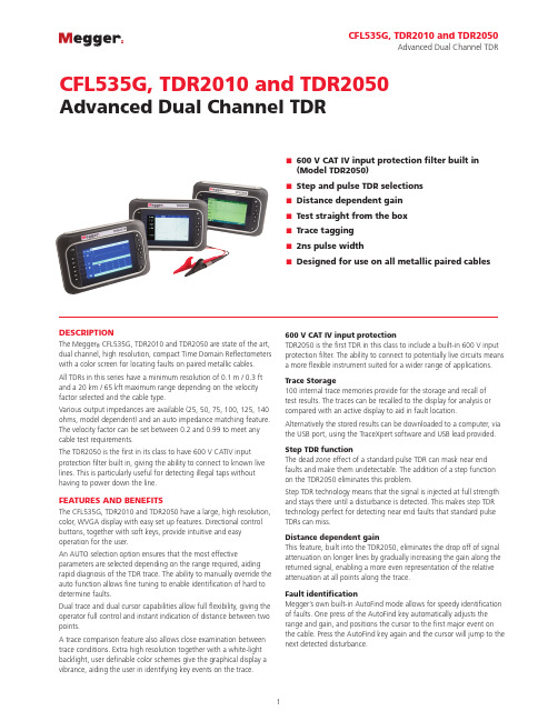
CFL535G, TDR2010 and TDR2050Advanced Dual Channel TDR■■600 V CAT IV input protection filter built in(Model TDR2050)■■Step and pulse TDR selections ■■Distance dependent gain ■■Test straight from the box ■■Trace tagging ■■2ns pulse width■■Designed for use on all metallic paired cablesDESCRIPTIONThe Megger ® CFL535G, TDR2010 and TDR2050 are state of the art, dual channel, high resolution, compact Time Domain Reflectometers with a color screen for locating faults on paired metallic cables. All TDRs in this series have a minimum resolution of 0.1 m / 0.3 ft and a 20 km / 65 kft maximum range depending on the velocity factor selected and the cable type.Various output impedances are available (25, 50, 75, 100, 125, 140 ohms, model dependent) and an auto impedance matching feature. The velocity factor can be set between 0.2 and 0.99 to meet any cable test requirements.The TDR2050 is the first in its class to have 600 V CATIV input protection filter built in, giving the ability to connect to known live lines. This is particularly useful for detecting illegal taps without having to power down the line.FEATURES AND BENEFITSThe CFL535G, TDR2010 and TDR2050 have a large, high resolution, color, WVGA display with easy set up features. Directional control buttons, together with soft keys, provide intuitive and easy operation for the user.An AUTO selection option ensures that the most effectiveparameters are selected depending on the range required, aiding rapid diagnosis of the TDR trace. The ability to manually override the auto function allows fine tuning to enable identification of hard to determine faults.Dual trace and dual cursor capabilities allow full flexibility, giving the operator full control and instant indication of distance between two points.A trace comparison feature also allows close examination between trace conditions. Extra high resolution together with a white-light backlight, user definable color schemes give the graphical display a vibrance, aiding the user in identifying key events on the trace.600 V CAT IV input protectionTDR2050 is the first TDR in this class to include a built-in 600 V input protection filter. The ability to connect to potentially live circuits means a more flexible instrument suited for a wider range of applications.Trace Storage100 internal trace memories provide for the storage and recall of test results. The traces can be recalled to the display for analysis or compared with an active display to aid in fault location.Alternatively the stored results can be downloaded to a computer, via the USB port, using the TraceXpert software and USB lead provided.Step TDR functionThe dead zone effect of a standard pulse TDR can mask near end faults and make them undetectable. The addition of a step function on the TDR2050 eliminates this problem.Step TDR technology means that the signal is injected at full strength and stays there until a disturbance is detected. This makes step TDR technology perfect for detecting near end faults that standard pulse TDRs can miss.Distance dependent gainThis feature, built into the TDR2050, eliminates the drop off of signal attenuation on longer lines by gradually increasing the gain along the returned signal, enabling a more even representation of the relative attenuation at all points along the trace.Fault identificationMegger’s own built-in AutoFind mode allows for speedy identification of faults. One press of the AutoFind key automatically adjusts the range and gain, and positions the cursor to the first major event on the cable. Press the AutoFind key again and the cursor will jump to the next detected disturbance.FindEnd functionTDR2050 also incorporates a FindEnd function, which allows the user to automatically search the trace to identify the end of the cable under test. This is useful in situations where a fast cable length measurement is required.For those who wish to maintain manual control, manual operation allows full override access to refine the response for easy fault identification.Color schemesThe very different light conditions that could be present when using the TDR2050, combined with the limitations of eye conditions such as color blindness, makes the addition of set color schemes in the instrument extremely important.TDR2010 and TDR2050 have 6 additional set color schemes on top of the Default and Outdoor schemes included on other Megger TDRs. There are also 2 custom slots where the user can specify their own scheme by setting up to 7 screen elements to their own choice of color.Trace TaggingTDR2010 and TDR2050 also incorporate a Trace Tagging feature which allows the user to add a name to saved traces. This could be the circuit ID, building name or any other identifying text the user wishes to save with the trace.A text string of up to 32 alphanumeric characters can be stored against each trace and this can consist of upper case letters including accents.TraceXpert PC softwareThe CFL535G, TDR2010 and TDR2050 come complete withthe Megger TraceXpert software which gives full control over downloading, reporting and uploading of saved trace results. Designed around a database and programmed for ease of use and simplicity, TraceXpert offers the ideal application for all your data processing requirements.Models include:CFL535GA fully featured high resolution TDR with backlit color display and powered by Li-ion rechargeable battery batteries. This model comes complete with 2 pairs of mini-clip Test Leads.TDR2010The same as the CFL535G but with Trace Tagging and additional Color Scheme selection.TDR2050The same as TDR2010 but with the addition of 600 V CAT IV rating, Step, DDG and FindEnd functions.ADDITIONAL FEATURES (MODEL DEPENDENT)■■Backlit graphics color LCD (800x480)■■Adjustable display contrast■■Resolution to 0.1 m■■USB connection to PC allowing upload and download of traces■■For use on Telecom TNV-3 circuit, or 150 V CAT IV power circuits (CFL535G and TDR2010 only)■■For use on power circuits to 600 V CAT IV (TDR2050 only)■■Power blocking filter built-in■■Environmental protection to IP54■■Selectable output impedance (25, 50, 75,100, 125 and 140 Ω)■■2ns pulse for near end fault location■■AUTO option selecting gain and pulse for each range■■AUTO option matches output impedance to cable■■Display distance in meters or feet■■Li-ion rechargeable battery (12 hours typical life) APPLICATIONS■■Personnel involved in the location of cable faults as part of a responsive or routine maintenance program.■■Electrical inspectors during quality checks following work onall new cable installations and modifications to existing cable installations.■■Testing reels of cable for shipping damage, cable shortages, cable usage, and inventory management.■■Testing for faults on hidden cabling in vehicles such as trains and airplanes where access is restricted and voltage may be present.■■Tracking down illegal connections (taps) on the power system.■■Checking for performance on umbilical cables in oceanographic and mining situations.■■Maintaining rail network signal communications and power cabling.■■Ensuring safe and efficient state of commercial heating and air conditioning cable.SPECIFICATIONSExcept where otherwise stated, this specification applies at an ambient temperature of 20°CGENERALRangeUp to 20000 m with a minimum resolution of 0.1 mm ft ns10 30 12525 80 25050 160 500100 320 100250 800 2500500 1600 50001000 3200 100002500 8000 250005000 16000 5000010000 32500 10000020000 65000 200000 Accuracy±1% of range ±1 pixel at 0.67 VF[Note - The measurement accuracy is for theindicated cursor position only and is conditionalon the velocity factor being correct. Resolution1% of rangeInput protection This instrument complies withIEC61010-1 to protect the user in theevent of connection to live systems.TDR2050 is rated at 600 V CAT IVwhie the other models are rated at150 V CAT IV. TDR2050 is specificallydesigned to allow use on energizedsystems up to the rated voltage. Allother models are designed for useon de-energized systems and fusedleads must be used if the potentialvoltage between terminals couldexceed 300 VOutput pulse Up to 20 volts peak to peak intoopen circuit. Pulse widths determinedby range, cable and model used. Gain Set for each range with userselectable steps (in Manual operatingmode)Velocity factor Variable from 0.2 to 0.99 in stepsof 0.01TX null AutomaticTrace Tagging - 32 characters chosenfrom upper case letters includingaccentsColor schemes - Default, Outdoor,CustomStep TDR - Eliminates the Dead Zoneeffect.DDG - Available in ranges 1000 mand above in 0.5 dB stepsCable Impedance - 25, 50, 75, 100,125, 140 ohm + AUTOPower down User programmable auto power offtimer 1, 5, 10 mins or never Battery Li-ion rechargeable batteryBattery charge time 6 hours at 0 °C to 40 °CBattery life12 hours typicalSafety These instruments comply withIEC61010-1 for connections to livesystems up to 150 V CAT IV or 300 VCAT III (2010 only).TDR2050 is rated at 600 V CAT IV.Fused leads must be used if thevoltage between terminals exceeds300 V.Compliant with EN60950-1,EN61010-1, UN38.3 and EN62133 EMC Complies with ElectromagneticCompatibility Specifications (Lightindustrial) BS EN 61326-1, with aminimum performance of ‘B’ for allimmunity tests.MECHANICALIP rating The instrument is designed for useindoors or outdoors and is ratedto IP54.Case ABSDimensions290 mm (11.4 in.) x 190 mm(7.5 in. x 55 mm (2.2 in.)Weight 1.7kg (3.8lbs)Connectors Four 4mm-safety terminals and twoF connectors. Other standard pushon adapters will fit. F connectorsnot available on TDR2050.Test lead 1.5 meters long consisting of2 x 4 mm shrouded connector tominiature crocodile clips(CFL535G and TDR2010) or1.5 meter fused leads (TDR2050) Display800 x 480 pixel color graphics LCD,viewable in external environments.Color SchemesSelectableCFL535G x2TDR2010, TDR2050 x8CustomCFL535G x1TDR2010, TDR2050 x2Backlight Permanent backlight with all colorschemes (adjustable brightness) ENVIRONMENTALOperating temperaturerange and humidity-15 °C to +50 °C (5 °F to 122 °F)<95% at +40 ºC non-condensing Storage temperaturerange and humidity-20 °C to 70 °C (-4 °F to 158 °F)<95% at +40 ºC non-condensingAdvanced Dual Channel TDRCERTIFICATION ISORegistered to ISO 9001:2000 Cert. no. Q 09290Registered to ISO 14001-1996 Cert. no. EMS 61597CFL535G_TDR2010_TDR2050_DS_US_Megger is a registered trademarkUKArchcliffe Road Dover CT17 9EN England T +44 (0) 1304 502101F +44 (0) 1304 207342******************UNITED STATES2621 Van Buren Avenue Norristown, PA 19403 USA T 1 866-254-0962 (USA only) T +1 610-676-8500 F +1 610-676-8625****************************OTHER TECHNICAL SALES OFFICES Dallas TX USA, College Station USA, Sydney AUSTRALIA, Täby SWEDEN, Ontario CANADA, Trappes FRANCE,Oberursel GERMANY, Aargau SWITZERLAND, Kingdom of BAHRAIN, Mumbai INDIA,Johannesburg SOUTH AFRICA, Chonburi THAILANDDescription Cat. No.TDR2050 Power TDR1005-023TDR2010 Dual Channel Comms 1005-449CLF535G Dual channel 1006-138Included accessoriesRetractable sheath fused test leads (1 pair) (TDR2050 only)1005-511Dual lead set with bed of nails clips (CFL535G and TDR2010 only) 6231-655Dual power lead set with fused clips (TDR2050 only) 1002-136Download kit 1003-353Carry case with straps 1003-217AC-DC power charger 1003-352Power cable25970-002Terminal adapter kit with BNC (CFL535G and TDR2010 only) 1003-218User guide CDDescription Cat. No.Optional accessoriesSingle power lead set with fused clips 1002-135Miniature clip test lead set (1 pair) 6231-652Bed of nails test lead set (1 pair) 6231-653Fused 500 mA test lead set (1 pair) 1002-015Replacement battery1002-552Terminal adapter kit (TDR2050 only) 1003-218AC power lead25970-002Dual power lead set with bed of nails clips (TDR2050 only)6231-655Dual fused lead set (CFL535G and TDR2010 only) 1002-136Dual power lead set with fused clips 1003-326Dual miniature clip test lead set 6231-654Short leadset BNC to croc clips 6231-694BNC adapter25965-154Retractable sheath fused test leads (1 pair)1005-511Advanced Dual Channel TDR。