路由器+3550 dhcp+限速 全配置(精成-王成伟)
3550中文配置手册
3550中文配置手册配置接口特性这一章详细说明交换机上的接口和描述这么配置他们。
这章有以下这些内容:z理解接口类型z使用接口命令z配置二层接口z监控和维护二层接口z配置三从接口注意:需要完整的有关该章的语法和应用信息,请参考Catalyst 3550 Multilayer Switch Command Reference和Cisco IOS Interface Command Reference for Release 12.1.理解接口类型这个部分描述了不同的接口类型,以及其它章节所包括的详细配置这些接口的一些参考内容。
其他章节描述了物理接口特性的配置过程。
这部分包括:•基于端口的VLAN (Port-Based VLANs)•交换端口 (Switch Ports)•以太网通道端口组 (EtherChannel Port Groups)•交换虚拟接口 (Switch Virtual Interfaces)•被路由端口 (Routed Ports)•连接接口 (Connecting Interfaces)基于端口的VLAN (Port-based Vlans)一个Vlan是一个按功能、组、或者应用被逻辑分段的交换网络,并不考虑使用者的物理位置。
要更多关于Vlan的信息请看“Configuring VLANS”。
一个端口上接受到的包被发往属于同一个Vlan的接收端口。
没有一个第三层的设备路由Vlan间的流量,不同Vlan的网络设备无法通讯。
为了配置普通范围(Normal-range) Vlan(Vlan IDs 1-1005),使用命令: config-vlan模式(global) vlan vlan-id或vlan-configuration模式(exec) vlan database针对Vlan ID 1-1005的vlan-configration模式被保存在vlan数据库中。
为配置扩展范围(extended-range) Vlans (Vlan ID 1006-4094),你必须使用config-vlan模式,并把VTP的模式设为transparent透明模式。
怎么设置路由器限速
怎么设置路由器限速
要设置路由器限速,可以按照以下步骤进行操作:
1. 打开浏览器,输入路由器的IP 地址,通常为19
2.168.1.1,然后按下Enter 键登录路由器管理界面。
2. 根据路由器品牌和型号,找到并点击“QoS(服务质量)”或“带宽控制”等相关选项。
3. 在QoS 或带宽控制页面,一般会有两种限速模式可供选择:基于设备或基于应用程序。
根据你的需求选择其中一种模式。
- 基于设备:可以限制某个特定设备的带宽。
选择该模式后,输入要限速的设备的IP 地址,然后设置相应的带宽限制。
- 基于应用程序:可以限制某个特定应用程序的带宽。
选择该模式后,输入要限速的应用程序的名称或端口号,然后设置相应的带宽限制。
4. 设置带宽限制时,可以选择上传速度和下载速度,并设定相应的带宽限制数值。
一般会提供Mbps(兆比特每秒)为单位来设置带宽。
例如,如果希望某个设备或应用程序的下载速度限制为2 Mbps,则输入该数值。
5. 完成设置后,点击“应用”或“保存”按钮保存设置。
注意事项:
- 不同的路由器品牌和型号可能具有不同的界面和选项名称,以上步骤仅供参考,具体步骤可能略有差异。
- 限速设置可能只对内部网络(局域网)有效,对外部网络(互联网)的限速效果可能有限。
- 设备和应用程序的IP 地址、名称或端口号可以在路由器的设备列表或网络设置中找到。
如果没有在路由器管理界面找到相关设置选项,或者更复杂的限速需求,可能需要参考路由器的用户手册或联系厂家进行进一步的指导。
DES系列交换机配置实例(3550、CLI模式为例)
DES3550配置实例(楼道用)DES3026、DES3550与DES3626都为二层交换机,一般作小区楼道交换机用,它们都是CLI命令行配置模式,配置命令基本一致,只是端口数量不同。
以下以DES3550配置实例进行标注解释。
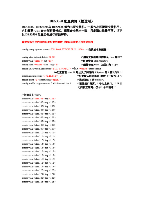
其中尖括号中的内容为要配置的参数(实际命令中不包含尖括号)config snmp system_name <YW-1603-FTSCH-ZL-H11100> /*交换机名称配置*/config vlan default delete <1-48>/*删除交换机端口的默认vlan端口*/ create vlan <vlan33> tag <33>/*创建管理vlan vlan33*/config vlan <vlan33> add tag <1>/*配置管理vlan, 上联口为1口*/ config ipif System ipaddress <172.18.37.98/27> vlan<vlan33> state enable/*配置管理vlan IP地址及子网掩码(System的S需大写)*/ create iprout default <172.18.37.97 1> /*配置默认网关地址跳数(一般为1)*/ config ports <1> description <uplink> /*描述端口1为uplink*/config traffic_segmentation 2-48 forward_list 1 /*配置端口隔离。
1号为上联口,2-28口之间相互隔离,仅与1号口连通*//*创建业务vlan*/create vlan <vlan101> tag <101>create vlan <vlan102> tag <102>create vlan <vlan103> tag <103>create vlan <vlan104> tag <104>create vlan <vlan105> tag <105>create vlan <vlan106> tag <106>create vlan <vlan107> tag <107>create vlan <vlan108> tag <108>create vlan <vlan109> tag <109>create vlan <vlan110> tag <110>create vlan <vlan111> tag <111>create vlan <vlan112> tag <112>create vlan <vlan113> tag <113>create vlan <vlan114> tag <114>create vlan <vlan115> tag <115>create vlan <vlan116> tag <116>create vlan <vlan117> tag <117>create vlan <vlan118> tag <118>create vlan <vlan119> tag <119>create vlan <vlan120> tag <120>create vlan <vlan121> tag <121>create vlan <vlan122> tag <122>create vlan <vlan123> tag <123>create vlan <vlan124> tag <124> create vlan <vlan125> tag <125> create vlan <vlan126> tag <126> create vlan <vlan127> tag <127> create vlan <vlan128> tag <128> create vlan <vlan129> tag <129> create vlan <vlan130> tag <130> create vlan <vlan131> tag <131> create vlan <vlan132> tag <132> create vlan <vlan133> tag <133> create vlan <vlan134> tag <134> create vlan <vlan135> tag <135> create vlan <vlan136> tag <136> create vlan <vlan137> tag <137> create vlan <vlan138> tag <138> create vlan <vlan139> tag <139> create vlan <vlan140> tag <140> create vlan <vlan141> tag <141> create vlan <vlan142> tag <142> create vlan <vlan143> tag <143> create vlan <vlan144> tag <144> create vlan <vlan145> tag <145> create vlan <vlan146> tag <146> create vlan <vlan147> tag <147> create vlan <vlan148> tag <148>/*为每个端口配置不同的端口*/ config vlan <vlan102>add untag <2> config vlan <vlan103> add untag <3> config vlan <vlan104> add untag <4> config vlan <vlan105> add untag <5> config vlan <vlan106> add untag <6> config vlan <vlan107> add untag <7> config vlan <vlan108> add untag <8> config vlan <vlan109> add untag <9> config vlan <vlan110> add untag <10> config vlan <vlan111> add untag <11> config vlan <vlan112> add untag <12> config vlan <vlan113> add untag <13> config vlan <vlan114> add untag <14> config vlan <vlan115> add untag <15> config vlan <vlan116> add untag <16> config vlan <vlan117> add untag <17> config vlan <vlan118> add untag <18>config vlan <vlan119> add untag <19> config vlan <vlan120> add untag <20> config vlan <vlan121> add untag <21> config vlan <vlan122> add untag <22> config vlan <vlan123> add untag <23> config vlan <vlan124> add untag <24> config vlan <vlan125> add untag <25> config vlan <vlan126> add untag <26> config vlan <vlan127> add untag <27> config vlan <vlan128> add untag <28> config vlan <vlan129> add untag <29> config vlan <vlan130> add untag <30> config vlan <vlan131> add untag <31> config vlan <vlan132> add untag <32> config vlan <vlan133> add untag <33> config vlan <vlan134> add untag <34> config vlan <vlan135> add untag <35> config vlan <vlan136> add untag <36> config vlan <vlan137> add untag <37> config vlan <vlan138> add untag <38> config vlan <vlan139> add untag <39> config vlan <vlan140> add untag <40> config vlan <vlan141> add untag <41> config vlan <vlan142> add untag <42> config vlan <vlan143> add untag <43> config vlan <vlan144> add untag <44> config vlan <vlan145> add untag <45> config vlan <vlan146> add untag <46> config vlan <vlan147> add untag <47> config vlan <vlan148> add untag <48>/*配置每个vlan的1口为上联口*/ config vlan <vlan102> add tag <1> config vlan <vlan103> add tag <1> config vlan <vlan104> add tag <1> config vlan <vlan105> add tag <1> config vlan <vlan106> add tag <1> config vlan <vlan107> add tag <1> config vlan <vlan108> add tag <1> config vlan <vlan109> add tag <1> config vlan <vlan110> add tag <1> config vlan <vlan111> add tag <1> config vlan <vlan112> add tag <1>config vlan <vlan113> add tag <1>config vlan <vlan114> add tag <1>config vlan <vlan115> add tag <1>config vlan <vlan116> add tag <1>config vlan <vlan117> add tag <1>config vlan <vlan118> add tag <1>config vlan <vlan119> add tag <1>config vlan <vlan120> add tag <1>config vlan <vlan121> add tag <1>config vlan <vlan122> add tag <1>config vlan <vlan123> add tag <1>config vlan <vlan124> add tag <1>config vlan <vlan125> add tag <1>config vlan <vlan126> add tag <1>config vlan <vlan127> add tag <1>config vlan <vlan128> add tag <1>config vlan <vlan129> add tag <1>config vlan <vlan130> add tag <1>config vlan <vlan131> add tag <1>config vlan <vlan132> add tag <1>config vlan <vlan133> add tag <1>config vlan <vlan134> add tag <1>config vlan <vlan135> add tag <1>config vlan <vlan136> add tag <1>config vlan <vlan137> add tag <1>config vlan <vlan138> add tag <1>config vlan <vlan139> add tag <1>config vlan <vlan140> add tag <1>config vlan <vlan141> add tag <1>config vlan <vlan142> add tag <1>config vlan <vlan143> add tag <1>config vlan <vlan144> add tag <1>config vlan <vlan145> add tag <1>config vlan <vlan146> add tag <1>config vlan <vlan147> add tag <1>config vlan <vlan148> add tag <1>/*配置snmp网管*/删除系统默认的public(ro)、private(rw)字符串,指定合法的字符串(rw)DHS-3618:4#delete snmp community publicDHS-3618:4#delete snmp community privateDHS-3618:4#create snmp community <合法字符串>view CommunityView <read_write |readonly >/*配置telnet和console*/设置超级用户aaa,并设置口令为bbbDHS-3618:4#create account admin <aaa>Command: create account admin <aaa>Enter a case-sensitive new password: <bbb>Enter the new password again for confirmation: <bbb>删除用户aaaDHS-3618:4#delete account <aaa>Command: delete account aaa在系统提示Are you sure to delete the last administrator account?(y/n) 时回答y。
CISCO3550交换机配置DHCP服务器实例网络知识 电脑资料
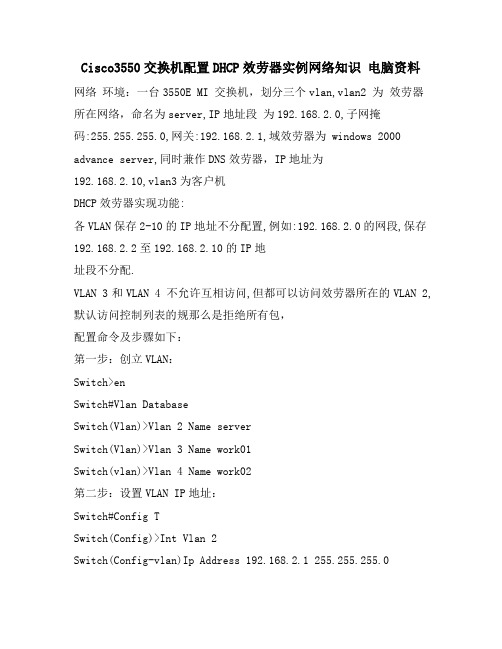
Cisco3550交换机配置DHCP效劳器实例网络知识电脑资料网络环境:一台3550E MI 交换机,划分三个vlan,vlan2 为效劳器所在网络,命名为server,IP地址段为192.168.2.0,子网掩码:255.255.255.0,网关:192.168.2.1,域效劳器为 windows 2000 advance server,同时兼作DNS效劳器,IP地址为192.168.2.10,vlan3为客户机DHCP效劳器实现功能:各VLAN保存2-10的IP地址不分配置,例如:192.168.2.0的网段,保存192.168.2.2至192.168.2.10的IP地址段不分配.VLAN 3和VLAN 4 不允许互相访问,但都可以访问效劳器所在的VLAN 2, 默认访问控制列表的规那么是拒绝所有包,配置命令及步骤如下:第一步:创立VLAN:Switch>enSwitch#Vlan DatabaseSwitch(Vlan)>Vlan 2 Name serverSwitch(Vlan)>Vlan 3 Name work01Switch(vlan)>Vlan 4 Name work02第二步:设置VLAN IP地址:Switch#Config TSwitch(Config)>Int Vlan 2Switch(Config-vlan)Ip Address 192.168.2.1 255.255.255.0Switch(Config-vlan)No ShutSwitch(Config-vlan)>Int Vlan 3Switch(Config-vlan)Ip Address 192.168.3.1 255.255.255.0 Switch(Config-vlan)No ShutSwitch(Config-vlan)>Int Vlan 4Switch(Config-vlan)Ip Address 192.168.4.1 255.255.255.0 Switch(Config-vlan)No ShutSwitch(Config-vlan)Exit/*注意:由于此时没有将端口分配置到VLAN2,3,4,所以各VLAN会DOWN掉,待将端口分配到各VLAN后,VLAN会起来*/第三步:设置端口全局参数Switch(Config)Interface Range Fa 0/1 - 24Switch(Config-if-range)Spanning-tree Portfast第四步:将端口添加到VLAN2,3,4中/*将端口1-8添加到VLAN 2*/Switch(Config)Interface Range Fa 0/1 - 8Switch(Config-if-range)Switchport Aess Vlan 2/*将端口9-16添加到VLAN 3*/Switch(Config)Interface Range Fa 0/9 - 16Switch(Config-if-range)Switchport Aess Vlan 3/*将端口17-24添加到VLAN 4*/Switch(Config)Interface Range Fa 0/17 - 24Switch(Config-if-range)Switchport Aess Vlan 4Switch(Config-if-range)Exit/*经过这一步后,各VLAN会起来*/第五步:配置3550作为DHCP效劳器/*VLAN 2可用地址池和相应参数的配置,有几个VLAN要设几个地址池*/Switch(Config)Ip Dhcp Pool Test01/*设置可分配的子网*/Switch(Config-pool)Network 192.168.2.0 255.255.255.0/*设置DNS效劳器*/Switch(Config-pool)Dns-server 192.168.2.10/*设置该子网的网关*/Switch(Config-pool)Default-router 192.168.2.1/*配置VLAN 3所用的地址池和相应参数*/Switch(Config)Ip Dhcp Pool Test02Switch(Config-pool)Network 192.168.3.0 255.255.255.0Switch(Config-pool)Dns-server 192.168.2.10Switch(Config-pool)Default-router 192.168.3.1/*配置VLAN 4所用的地址池和相应参数*/Switch(Config)Ip Dhcp Pool Test03Switch(Config-pool)Network 192.168.4.0 255.255.255.0Switch(Config-pool)Dns-server 192.168.2.10Switch(Config-pool)Default-router 192.168.4.1第六步:设置DHCP保存不分配的地址Switch(Config)Ip Dhcp Excluded-address 192.168.2.2192.168.2.10Switch(Config)Ip Dhcp Excluded-address 192.168.3.2192.168.3.10Switch(Config)Ip Dhcp Excluded-address 192.168.4.2192.168.4.10第七步:启用路由/*路由启用后,各VLAN间主机可互相访问*/Switch(Config)Ip Routing第八步:配置访问控制列表Switch(Config)aess-list 103 permit ip 192.168.2.0 0.0.0.255 192.168.3.0 0.0.0.255Switch(Config)aess-list 103 permit ip 192.168.3.0 0.0.0.255 192.168.2.0 0.0.0.255Switch(Config)aess-list 103 permit udp any any eq bootpc Switch(Config)aess-list 103 permit udp any any eq tftp Switch(Config)aess-list 103 permit udp any eq bootpc any Switch(Config)aess-list 103 permit udp any eq tftp any Switch(Config)aess-list 104 permit ip 192.168.2.0 0.0.0.255 192.168.4.0 0.0.0.255Switch(Config)aess-list 104 permit ip 192.168.4.0 0.0.0.255 192.168.2.0 0.0.0.255Switch(Config)aess-list 104 permit udp any eq tftp any Switch(Config)aess-list 104 permit udp any eq bootpc any Switch(Config)aess-list 104 permit udp any eq bootpc any Switch(Config)aess-list 104 permit udp any eq tftp any第九步:应用访问控制列表/*将访问控制列表应用到VLAN 3和VLAN 4,VLAN 2不需要*/ Switch(Config)Int Vlan 3Switch(Config-vlan)ip aess-group 103 outSwitch(Config-vlan)Int Vlan 4Switch(Config-vlan)ip aess-group 104 out第十步:结束并保存配置Switch(Config-vlan)EndSwitch#Copy Run Start原文转自:.ltesting.模板,内容仅供参考。
思科交换机3550配置手册(修改后)
交换机简介⏹连接方式Telnet、WebBrower、网管软件、console(控制线)⏹性能参数基本配置⏹状态转换⏹用户属性及密码修改⏹查看MAC地址#show mac-address-table⏹端口基本配置(单/组)speed/duplexDescription⏹保存或更改设置#copy running-configure startup-configure#delete flash:vlan.dat#erase startup-configure#reload⏹MAC地址配置使用说明⏹命令缩写⏹?及Tab键的使用⏹为防止由于输入的命令错误引起的等待,禁止设备查找DNS服务器#no ip domain-lookup;⏹有效的范围:vlan从1 到4094fastethernet槽位/{first port} - {last port}, 槽位为0gigabitethernet槽位/{first port} - {last port},槽位为0⏹端口优先及通常为4096的倍数,而权植为16的倍数;VLAN配置⏹VLAN 简介⏹创建VLAN(基于静态端口)新建划分端口⏹查看VLAN配置⏹删除VLAN⏹问题:物理端口与可支持VLAN数目不相匹配;⏹命令行:switch>enswitch #vlan database //新建Vlan1switch (vlan)vlan 1name VLAN1switch #configure terminalswitch (config)int g0/1 //划分端口g0/1switch(config-if)switch mode accessswitch(config-if)switch access vlan 1TRUNK设置⏹TRUNK简介⏹数据封装类型dot1islnegotiate⏹配置trunk⏹定义trunk允许通过的vlan switch trunk allowed vlan …⏹Native vlan 意义及更改(如果trunk链路两端的native vlan不一致时,交换机将会报错)⏹DTP简介对于CISCO交换机之间的链路是否形成TRUNK,可以通过DTP(Dynamic Trunk Protocol)进行协商。
3550交换机简要配置手册(中文)

3550交换机(EMI)简明配置维护手册中望商业机器公司2002-12-10目录说明 (3)产品特性 (3)配置端口 (4)配置一组端口 (4)配置二层端口 (6)配置端口速率及双工模式 (6)端口描述 (7)配置三层口 (8)监控及维护端口 (10)监控端口和控制器的状态 (10)刷新、重置端口及计数器 (12)关闭和打开端口 (13)配置VLAN (14)理解VLAN (14)可支持的VLAN (15)配置正常范围的VLAN (15)生成、修改以太网VLAN (15)删除VLAN (17)将端口分配给一个VLAN (18)配置VLAN Trunks (19)使用STP实现负载均衡 (22)说明本手册只包括日常使用的有关命令及特性,其它未涉及的命令及特性请参考英文的详细配置手册。
产品特性3550EMI是支持二层、三层功能(EMI)的交换机支持VLAN∙到1005 个VLAN∙支持VLAN ID从1到4094(IEEE 802.1Q 标准)∙支持ISL及IEEE 802.1Q封装安全∙支持IOS标准的密码保护∙静态MAC地址映射∙标准及扩展的访问列表支持,对于路由端口支持入出双向的访问列表,对于二层端口支持入的访问列表∙支持基于VLAN的访问列表3层支持(需要多层交换的IOS)∙HSRP∙IP路由协议o RIP versions 1 and 2o OSPFo IGRP及EIGRPo BGP Version 4监视∙交换机LED指示端口状态∙SPAN及远端SPAN (RSPAN) 可以监视任何端口或VLAN的流量∙内置支持四组的RMON监控功能(历史、统计、告警及事件)∙Syslog功能其它功能:支持以下的GBIC模块:∙1000BASE-T GBIC: 铜线最长100 m∙1000BASE-SX GBIC: 光纤最长1804 feet (550 m)∙1000BASE-LX/LH GBIC: 光纤最长32,808 feet (6 miles or 10 km)∙1000BASE-ZX GBIC: 光纤最长328,084 feet (62 miles or 100 km) 配置端口配置一组端口当使用interface range命令时有如下的规则:∙有效的组范围:o vlan从1 到4094o fastethernet槽位/{first port} - {last port}, 槽位为0o gigabitethernet槽位/{first port} - {last port},槽位为0o port-channel port-channel-number - port-channel-number, port-channel号从1到64∙端口号之间需要加入空格,如:interface range fastethernet 0/1 – 5是有效的,而interface range fastethernet 0/1-5是无效的.∙interface range命令只能配置已经存在的interface vlan∙所有在同一组的端口必须是相同类别的。
Cisco3550的配置命令手册
Cisco3550的配置命令手册为了使两个或多个交换机在同一个MST区域,你必须有相同的VLAN到实例映射,相同的配置修正号,和相同的名字。
从特权模式开始,跟着这些步骤指派MST区域配置和启用MSTP。
这个过程是必需的。
命令目的Step 1 configure terminal 进入全局配置模式Step 2 spanning-tree mst configuration 进入MST配置模式Step 3 instance instance-id vlan vlan-range 映射VLAN到一个MST实例对于instance-id, 范围从1到15。
对于vlan vlan-range, 范围从1到4094。
当你映射一个VLAN到MST实例, 映射增大, 并且被指定的VLAN 范围被增加或被移动到现有的一个实例当中。
为了指定一个范围, 使用一个连字号;例如, instance 1 vlan 1-63 映射VLAN1至63到MST实例1。
为指定一个系列, 使用一个逗号;例如, instance 1 vlan 10, 20, 30 映射VLAN10,20,和30到MST 实例1.Step 4 name name 指定配置名。
该name 字符串有最大32个字符串并区分大小写。
Step 5 revision version 指定配置修订号数字. 范围是0到65535.Step 6 show pending 显示等待配置来确认你的配置Step 7 exit 应用所有改变, 并返回到全局配置模式.Step 8 spanning-tree mode mst 起用MSTP。
RSTP 也被启用。
注意改变生成树模式会中断流量,因为所有以前的生成树实例被停止,并启用一个新的生成树实例。
在同一时间,你不能同时运行MSTP和PVSTStep 9 end 返回特权模式Step 10 show running-config 确认你的条目Step 11 copy running-config startup-config (可选)在配置文件中保存你的条目为了返回缺省MST区域配置,使用命令:(global) no spanning-tree mst configuration为了返回缺省VLAN实例映射,使用命令:(config-mst) no instance instance-id [vlan vlan-range]为了返回缺省名,使用命令:(config-mst) no name为了返回缺省修正号,使用命令:(config-mst) no revision为了重新启用PVST,使用命令:(config) spanning-tree mode pvst这个例子显示怎样进入MST配置模式,映射VLAN10-20进入MST实例1,命名区域region1,设置配置修正号1,显示挂起的配置,应用变化,并且返回全局配置模式:Switch(config)# spanning-tree mst configurationSwitch(config-mst)# instance 1 vlan 10-20Switch(config-mst)# name region1Switch(config-mst)# revision 1Switch(config-mst)# show pendingPending MST configurationName [region1]Revision 1Instance Vlans Mapped-------- ---------------------0 1-9,21-40941 10-20-------------------------------Switch(config-mst)# exitSwitch(config)#配置根交换机交换机为映射到他的VLANs保持一个生成树实例。
cisco3550怎么配置dhcp
cisco3550怎么配置dhcp思科cisco制造的路由器设备、交换机和其他设备承载了全球80%的互联网通信,成为硅谷中新经济的传奇,那么你知道cisco 3550怎么配置dhcp吗?下面是店铺整理的一些关于cisco 3550怎么配置dhcp的相关资料,供你参考。
例如一台3550EMI交换机,划分三个vlan,vlan2为服务器所在网络,命名为server,IP 地址段为192.168.2.0,子网掩码:255.255.255.0,网关:192.168.2.1,域服务器为 windows2000advanceserver,同时兼作DHCP服务器,DNS服务器,IP地址为192.168.2.10,vlan3为客户机1 所在网络,IP地址段为192.168.3.0,子网掩码:255.255.255.0,网关:192.168.3.1命名为work01,vlan4为客户机2所在网络,命名为work02,IP地址段为192.168.4.0,子网掩码:255.255.255.0,网关:192.168.4.1.3550上端口1-8划到VLAN2,端口9-16划分到VLAN3,端口17-24划分到VLAN4.cisco 3550配置dhcp第一步:创建VLAN:Switch>VlanDatabaseSwitch(Vlan)>Vlan2NameserverSwitch(Vlan)>Vlan3Namework01Switch(vlan)>Vlan4Namework02cisco 3550配置dhcp第二步:启用DHCP中继代理:/*关键一步,若缺少以下两条命令,在VLAN中使用“IPHELPER-ADDRESSDHCP服务器地址”指定DHCP服务器,客户机仍然不能获得IP地址*/Switch>EnableSwitch#ConfigtSwitch(Config)ServiceDhcpSwitch(Config)IpDhcpRelayInformationOptioncisco 3550配置dhcp第三步:设置VLANIP地址:Switch(Config)>IntVlan2Switch(Config-vlan)IpAddress192.168.2.1255.255.255.0Switch(Config-vlan)NoShutSwitch(Config-vlan)>IntVlan3Switch(Config-vlan)IpAddress192.168.3.1255.255.255.0Switch(Config-vlan)NoShutSwitch(Config-vlan)>IntVlan4Switch(Config-vlan)IpAddress192.168.4.1255.255.255.0Switch(Config-vlan)NoShutSwitch(Config-vlan)Exit/*注意:由于此时没有将端口分配置到VLAN2,3,4,所以各VLAN会DOWN掉,待将端口分配到各VLAN后,VLAN会起来*/ cisco 3550配置dhcp 第四步:设置端口全局参数Switch(Config)InterfaceRangeFa0/1-24Switch(Config-if-range)SwitchportModeAccessSwitch(Config-if-range)Spanning-treePortfastcisco 3550配置dhcp第五步:将端口添加到VLAN2,3,4中/*将端口1-8添加到VLAN2*/Switch(Config)InterfaceRangeFa0/1-8Switch(Config-if-range)SwitchportAccessVlan2/*将端口9-16添加到VLAN3*/Switch(Config)InterfaceRangeFa0/9-16Switch(Config-if-range)SwitchportAccessVlan3/*将端口17-24添加到VLAN4*/Switch(Config)InterfaceRangeFa0/17-24Switch(Config-if-range)SwitchportAccessVlan4Switch(Config-if-range)Exit/*经过这一步后,各VLAN会起来*/cisco 3550配置dhcp第六步:在VLAN3和4中设定DHCP服务器地址/*VLAN2中不须指定DHCP服务器地址*/Switch(Config)IntVlan3Switch(Config-vlan)IpHelper-address192.168.2.10Switch(Config)IntVlan4Switch(Config-vlan)IpHelper-address192.168.2.10cisco 3550配置dhcp第七步:启用路由/*路由启用后,各VLAN间主机可互相访问,若需进一步控制访问权限,则需应用到访问控制列表*/Switch(Config)IpRoutingcisco 3550配置dhcp第八步:结束并保存配置Switch(Config-vlan)EndSwitch#CopyRunStart。
锐捷S3550系列交换机基本配置命令
锐捷S3550系列交换机基本配置命令交换机的几种命令模式:1、用户模式 Switch> 首先进入该模式2、特权模式 Switch# 在用户模式下键入 enable 进入该模式3、全局配置模式 Switch(config)# 在特权模式下键入 configure 进入该模式4、接口配置模式 Switch(config-if)# 在全局配置模式使用 interface 命令进入该模式5、VLAN配置模式 Switch(config-vlan)# 在全局配置模式使用 vlan vlan_id 命令进入该模式一、交换机管理(一)限制访问交换机的方式在全局配置模式下1、no enable services telnet-server* 关闭交换机Telnet Server2、enable services telnet-server* 开启交换机Telnet Server3、no enable services web-server* 关闭交换机web Server4、enable services web-server* 开启交换机web Server5、no enable services snmap-agent* 关闭交换机SNMP Agent6、enable services snmap-agent* 开启交换机SNMP Agent7、services telnet host 10.0.240.81* 指定能使用Telnet方式管理交换机的合法用户的IP地址10.0.240.818、no services telnet host 10.0.240.81* 删除指定地能使用Telnet方式管理交换机的合法用户的IP地址10.0.240.819、services web host 10.0.240.81* 指定能使用Web方式管理交换机的合法用户的IP地址10.0.240.8110、no services web host 10.0.240.81* 删除指定的能使用Web方式管理交换机的合法用户的IP地址10.0.240.8111、no services telnet host* 删除所有能使用Telnet方式管理交换机的合法用户的IP地址12、no services web host* 删除所有能使用Web方式管理交换机的合法用户的IP地址在特权模式下13、show services* 显示对交换机的各种访问方式的状态14、copy running-config startup-config* 保存现有配置(二)通过命令授权控制用户的访问在全局配置模式下1、enable secret level 15 5 8888* 创建一个15级(最高授权级别)的使用锐捷私有加密算法(用5表示)的用户口令8888 2、enable secret 8888* 创建一个缺省为15级(最高授权级别)的用户口令88883、no enable secret* 删除用户口令(三)管理系统日期和时间在特权模式下1、clock set 15:20:00 12 1 2010* 将系统时间设置为2010年1月12日下午3点20分2、show clock* 显示当前系统时间信息(四)管理定时重启交换机在特权模式下1、reload* 立即重启系统2、reload in 10* 10分钟后重启系统3、reload at 12:00 12 1 2010* 在2010年1月12日12点重启系统4、reload cancel* 取消设置的重启计划(五)配置系统名称和命令提示符缺省情况下系统名称和系统命令提示符均为“Switch”在全局模式下1、hostname QJSYXX-3550-12G* 设置系统名称为QJSYXX-3550-12G2、no hostname* 恢复缺省的系统名称3、prompt QJSYXX* 设置命令提示符为QJSYXX4、no prompt* 恢复缺省的命令提示符在特权模式下5、show snmp* 查看系统名称(六)管理MAC地址表MAC地址表缺省配置:地址老化时间:300秒动态地址表:自动学习静态地址表:没有配置过滤地址表:没有配置在全局模式下1、mac-address-table aging-time 100* 设置MAC地址老化时间为100秒2、no mac-address-table aging-time* 将MAC地址老化时间恢复为缺省值3、clear mac-address-table dynamic* 删除交换机上所有的动态地址表4、clear mac-address-table dynamic 00d0.f800.073c* 删除特定MAC地址00d0.f800.073c5、clear mac-address-table dynamic interface gigabitethernet 0/3* 删除特定物理端口gigabitethernet 0/3上的所有动态MAC地址6、clear mac-address-table dynamic vlan 4* 删除VLAN 4上所有的动态MAC地址7、mac-address-table static 00d0.f800.073c vlan 4 interface gigabitethernet 0/3 * 配置静态地址表项在VLAN 4 中将目的地址为00d0.f800.073c的包转发到指定的gigabitethernet 0/3端口上8、no mac-address-table static 00d0.f800.073c vlan 4interface gigabitethernet 0/3 * 删除已配置的一个静态地址表项9、mac-address-table filtering 00d0.f800.073c vlan 1* 配置过滤地址表项让交换机过滤掉VLAN 1 内源MAC地址为00d0.f800.073c的包10、no mac-address-table filtering 00d0.f800.073c vlan 1* 删除已配置的一个过滤地址表项在特权模式下10、show mac-address-table address* 显示所有类型的地址信息11、show mac-address-table aging-time* 显示当前地址老化时间12、show mac-address-table dynamic* 显示所有动态地址信息13、show mac-address-table static* 显示所有静态地址信息14、show mac-address-table filtering* 显示所有过滤地址信息15、show mac-address-table interface* 显示接口gigabitethernet 0/1的所有类型的地址信息16、show mac-address-table vlan* 显示VLAN 1中所有类型的地址信息17、show mac-address-table count* 显示地址表中MAC地址的统计信息(七)IP和MAC地址绑定在全局配置模式下1、address-bind 10.0.240.88 00d0.f800.073c* 将IP地址10.0.240.88与MAC地址00d0.f800.073c进行绑定2、no address-bind 10.0.240.88* 取消IP地址10.0.240.88和MAC地址的绑定在特权模式下3、show address-bind* 查看地址绑定表(八)查看系统信息在特权模式下1、show version* 显示系统版本信息2、show version devices* 显示硬件版本信息3、show version slots* 显示当前的插槽和模块信息(九)设置串口速率、串口和Telnet超时时间缺省的串口传输速率为9600bps,缺省串口的超时时间为10分钟,Telnet的超时时间为5分钟在全局模式下1、line console 0speed 19200* 设置串口传输速率为19200bps在特权模式下2、show line console 0* 查看当前串口传输速率在全局配置模式下3、line console 0exec-timeout 3600* 配置串口的超时时间为3600秒(0-3600,0表示不超时)4、line vtyexec-timeout 3600* 配置Telnet的超时时间为3600秒(0-3600,0表示不超时)5、default exec-timeout* 将串口或Telnet的超时时间恢复为缺省值在特权模式下6、show line console 0* 显示当前串口超时时间7、show line vty* 显示当前Telnet超时时间(十)通过Telnet方式管理在命令提示符下telnet 10.0.240.254* 通过telnet方式登录到IP地址为10.0.240.254的交换机二、配置接口S3550-12G交换机接口类型1、2层接口(1)Switch Port(交换端口)由交换机上的单个物理端口构成,只有2层交换功能,又分为Access Port和Trunk Port。
Cisco 3550交换机配置DHCP服务器实例
网络环境:一台3550EMI交换机,划分三个vlan,vlan2 为服务器所在网络,命名为server,IP地址段为192.168.2.0,子网掩码:255.255.255.0,网关:192.168.2.1,域服务器为windows 2000 advance server,同时兼作DNS服务器,IP地址为192.168.2.10,vlan3为客户机1所在网络,IP地址段为192.168.3.0,子网掩码:255.255.255.0,网关:192.168.3.1命名为work01,vlan4为客户机2所在网络,命名为work02,IP地址段为192.168.4.0,子网掩码:255.255.255.0,网关:192.168.4.1,3550作DHCP服务器,端口1-8划到VLAN 2,端口9-16划分到VLAN 3,端口17-24划分到VLAN 4.DHCP服务器实现功能:各VLAN保留2-10的IP地址不分配置,例如:192.168.2.0的网段,保留192.168.2.2至192.168.2.10的IP地址段不分配.安全要求:VLAN 3和VLAN 4 不允许互相访问,但都可以访问服务器所在的VLAN 2,默认访问控制列表的规则是拒绝所有包。
配置命令及步骤如下:第一步:创建VLAN:Switch>enSwitch#Vlan DatabaseSwitch(Vlan)>Vlan 2 Name serverSwitch(Vlan)>Vlan 3 Name work01Switch(vlan)>Vlan 4 Name work02第二步:设置VLAN IP地址:Switch#Config TSwitch(Config)>Int Vlan 2Switch(Config-vlan)Ip Address 192.168.2.1 255.255.255.0Switch(Config-vlan)No ShutSwitch(Config-vlan)>Int Vlan 3Switch(Config-vlan)Ip Address 192.168.3.1 255.255.255.0Switch(Config-vlan)No ShutSwitch(Config-vlan)>Int Vlan 4Switch(Config-vlan)Ip Address 192.168.4.1 255.255.255.0Switch(Config-vlan)No ShutSwitch(Config-vlan)Exit/*注意:由于此时没有将端口分配置到VLAN2,3,4,所以各VLAN会DOWN掉,待将端口分配到各VLAN后,VLAN会起来*/第三步:设置端口全局参数Switch(Config)Interface Range Fa 0/1 - 24Switch(Config-if-range)Switchport Mode AccessSwitch(Config-if-range)Spanning-tree Portfast第四步:将端口添加到VLAN2,3,4中/*将端口1-8添加到VLAN 2*/Switch(Config)Interface Range Fa 0/1 - 8Switch(Config-if-range)Switchport Access Vlan 2/*将端口9-16添加到VLAN 3*/Switch(Config)Interface Range Fa 0/9 - 16Switch(Config-if-range)Switchport Access Vlan 3/*将端口17-24添加到VLAN 4*/Switch(Config)Interface Range Fa 0/17 - 24Switch(Config-if-range)Switchport Access Vlan 4Switch(Config-if-range)Exit/*经过这一步后,各VLAN会起来*/第五步:配置3550作为DHCP服务器/*VLAN 2可用地址池和相应参数的配置,有几个VLAN要设几个地址池*/ Switch(Config)Ip Dhcp Pool Test01/*设置可分配的子网*/Switch(Config-pool)Network 192.168.2.0 255.255.255.0/*设置DNS服务器*/Switch(Config-pool)Dns-server 192.168.2.10/*设置该子网的网关*/Switch(Config-pool)Default-router 192.168.2.1/*配置VLAN 3所用的地址池和相应参数*/Switch(Config)Ip Dhcp Pool Test02Switch(Config-pool)Network 192.168.3.0 255.255.255.0Switch(Config-pool)Dns-server 192.168.2.10Switch(Config-pool)Default-router 192.168.3.1/*配置VLAN 4所用的地址池和相应参数*/Switch(Config)Ip Dhcp Pool Test03Switch(Config-pool)Network 192.168.4.0 255.255.255.0Switch(Config-pool)Dns-server 192.168.2.10Switch(Config-pool)Default-router 192.168.4.1第六步:设置DHCP保留不分配的地址Switch(Config)Ip Dhcp Excluded-address 192.168.2.2 192.168.2.10Switch(Config)Ip Dhcp Excluded-address 192.168.3.2 192.168.3.10Switch(Config)Ip Dhcp Excluded-address 192.168.4.2 192.168.4.10第七步:启用路由/*路由启用后,各VLAN间主机可互相访问*/Switch(Config)Ip Routing第八步:配置访问控制列表Switch(Config)access-list 103 permit ip 192.168.2.0 0.0.0.255 192.168.3.0 0.0.0.255Switch(Config)access-list 103 permit ip 192.168.3.0 0.0.0.255 192.168.2.0 0.0.0.255Switch(Config)access-list 103 permit udp any any eq bootpcSwitch(Config)access-list 103 permit udp any any eq tftpSwitch(Config)access-list 103 permit udp any eq bootpc anySwitch(Config)access-list 103 permit udp any eq tftp anySwitch(Config)access-list 104 permit ip 192.168.2.0 0.0.0.255 192.168.4.0 0.0.0.255Switch(Config)access-list 104 permit ip 192.168.4.0 0.0.0.255 192.168.2.0 0.0.0.255Switch(Config)access-list 104 permit udp any eq tftp anySwitch(Config)access-list 104 permit udp any eq bootpc anySwitch(Config)access-list 104 permit udp any eq bootpc anySwitch(Config)access-list 104 permit udp any eq tftp any第九步:应用访问控制列表/*将访问控制列表应用到VLAN 3和VLAN 4,VLAN 2不需要*/Switch(Config)Int Vlan 3Switch(Config-vlan)ip access-group 103 outSwitch(Config-vlan)Int Vlan 4Switch(Config-vlan)ip access-group 104 out第十步:结束并保存配置Switch(Config-vlan)End如何实现IP访问控制列表ACLs 的全称为访问控制列表(Access Control Lists)。
- 1、下载文档前请自行甄别文档内容的完整性,平台不提供额外的编辑、内容补充、找答案等附加服务。
- 2、"仅部分预览"的文档,不可在线预览部分如存在完整性等问题,可反馈申请退款(可完整预览的文档不适用该条件!)。
- 3、如文档侵犯您的权益,请联系客服反馈,我们会尽快为您处理(人工客服工作时间:9:00-18:30)。
路由器+3550 dhcp+限速全配置路由器!version 12.2service timestamps debug uptimeservice timestamps log uptimeservice password-encryption!hostname aaa!logging buffered 100000 debuggingenable secret 5 $1$hlqZ$99SkyO3d3x7F26tmdt5G/.!username aaa password 7 04510A050438ip subnet-zero!!ip name-server a.a.a.aip dhcp excluded-address 192.168.188.1 192.168.188.2 !ip dhcp pool testnetwork 192.168.188.0 255.255.255.0dns-server a.a.a.adefault-router 192.168.188.1!!controller E1 1/0!controller E1 1/1!!!interface FastEthernet0/0ip address 192.168.188.1 255.255.255.0ip nat insideduplex autospeed auto!interface FastEthernet0/1ip address b.b.b.b 255.255.255.224ip nat outsideduplex autospeed auto!interface FastEthernet0/1.1!interface FastEthernet0/1.2!ip nat inside source list 3 interface FastEthernet0/1 overload ip classlessip route 0.0.0.0 0.0.0.0 b.b.b.cip route 192.168.189.0 255.255.255.0 192.168.188.2ip route 192.168.190.0 255.255.255.0 192.168.188.2ip route 192.168.191.0 255.255.255.0 192.168.188.2ip route 192.168.192.0 255.255.255.0 192.168.188.2ip route 192.168.193.0 255.255.255.0 192.168.188.2ip route 192.168.194.0 255.255.255.0 192.168.188.2no ip http serverno ip pim bidir-enable!!access-list 3 permit 192.168.188.0 0.0.0.255access-list 3 permit 192.168.189.0 0.0.0.255access-list 3 permit 192.168.194.0 0.0.0.255access-list 3 permit 192.168.193.0 0.0.0.255access-list 3 permit 192.168.192.0 0.0.0.255line con 0line aux 0line vty 0 4exec-timeout 5 0password 7 0501070C2A55login local!!end3550配置!version 12.1no service padservice timestamps debug uptimeservice timestamps log uptimeservice password-encryption 启用密码暗文!hostname xxxxxx!enable secret 5 $1$rM89$om4J1J8M1JK78d03GkIE8/enable password 7 111103061911!username xxxxx password 7 082B4D4D0200 用于用户telnet 登陆ip subnet-zeroip routingip name-server x.x.x.x!////////////3550 emi dhcp 配置ip dhcp pool YONGHU (地址池名lease 0 0 5 (租约——)network 192.168.194.0 255.255.255.0 [要分配的地址] [掩码]default-router 192.168.194.1 默认网关dns-server x.x.x.x dns服务器地址!////////////////对192。
168。
193。
0 网络段用户对用户限速mls qos!class-map match-all wochina 创建分类映射并进入分类映射配置模式。
. match access-group 110 定义分类通信的匹配条件。
!!丢弃所匹配的数据包policy-map testclass wochinapolice 16000 8000 exceed-action drop 16000 和8000 为BIT!spanning-tree extend system-id!!!interface FastEthernet0/1switchport trunk encapsulation dot1q no ip address!interface FastEthernet0/2switchport access vlan 2no ip addressservice-policy input wochina /////映射!interface FastEthernet0/3switchport access vlan 3no ip address!interface FastEthernet0/4 启用三层no switchportip address 192.168.192.1 255.255.255.0 interface FastEthernet0/5no ip address!interface FastEthernet0/6no ip address!interface FastEthernet0/7no ip address!interface FastEthernet0/8no ip address!interface FastEthernet0/9no ip address!interface FastEthernet0/10no ip address!interface FastEthernet0/11no ip address!no ip address!interface FastEthernet0/13 no ip address!interface FastEthernet0/14 no ip address!interface FastEthernet0/15 no ip address!interface FastEthernet0/16 no ip address!interface FastEthernet0/17 no ip address!interface FastEthernet0/18 no ip address!interface FastEthernet0/19 no ip address!interface FastEthernet0/20 no ip address!interface FastEthernet0/21 no ip address!interface FastEthernet0/22 no ip address!interface FastEthernet0/23 switchport access vlan 2no ip address!interface FastEthernet0/24 no switchport!interface GigabitEthernet0/1 no ip address!no ip address!interface Vlan1ip address 192.168.188.2 255.255.255.0!interface Vlan2ip address 192.168.193.1 255.255.255.0ip access-group 2 out!interface Vlan3ip address 192.168.194.1 255.255.255.0!interface Vlan4no ip address!interface Vlan6no ip address!ip classlessip route 0.0.0.0 0.0.0.0 192.168.188.1ip http server!!!access-list 2 deny 192.168.193.3access-list 2 permit anyaccess-list 110 permit ip 192.168.193.0 0.0.0.255 any !line con 0line vty 0 4password 7 021E1E580505login localline vty 5 15password 7 05131C0C2F4Flogin local!endwochina 上传了这个图片:。