超声波测距仪外文翻译
激光测距仪外文翻译

Laser rangefinderA long range laser rangefinder is capable of measuring distance up to 20 km; mounted on a tripod with an angular mount. The resulting system also provides azimuth and elevation measurements.A laser rangefinder is a device which uses a laser beam to determine the distance to an object. The most common form of laser rangefinder operates on the time of flight principle by sending a laser pulse in a narrow beam towards the object and measuring the time taken by the pulse to be reflected off the target and returned to the sender. Due to the high speed of light, this technique is not appropriate for high precision sub-millimeter measurements, where triangulation and other techniques are often used.PulseThe pulse may be coded to reduce the chance that the rangefinder can be jammed. It is possible to use Doppler effect techniques to judge whether the object is moving towards or away from the rangefinder, and if so how fast.PrecisionThe precision of the instrument is determined by the rise or fall time of the laser pulse and the speed of the receiver. One that uses very sharp laser pulses and has a very fast detector can range an object to within a few millimeters.RangeDespite the beam being narrow, it will eventually spread over long distances due to the divergence of the laser beam, as well as due to scintillation and beam wander effects, caused by the presence of air bubbles in the air acting as lenses ranging in size from microscopic to roughly half the height of the laser beam's path above the earth. These atmospheric distortions coupled with the divergence of the laser itself and with transverse winds that serve to push the atmospheric heat bubbles laterally may combine to make it difficult to get an accurate reading of the distance of an object, say, beneath some trees or behind bushes, or even over long distances of more than 1 km in open and unobscured desert terrain.Some of the laser light might reflect off leaves or branches which are closer thanthe object, giving an early return and a reading which is too low. Alternatively, over distances longer than 1200 ft (365 m), the target, if in proximity to the earth, may simply vanish into a mirage, caused by temperature gradients in the air in proximity to the heated surface bending the laser light. All these effects have to be taken into account.CalculationThe distance between point A and B is given byD=ct/2where c is the speed of light in the atmosphere and t is the amount of time for the round-trip between A and B.where is the delay which made by the light traveling and is the angular frequency of optical modulation.Then substitute the values in the equation D=ct/2,D=1/2 ct=1/2 c·φ/ω=c/(4πf) (Nπ+Δφ)=c/4f (N+ΔN)=U(N+)in this equation, U stands for the unit length.Δφ stands for the delay part which does not fulfill π.ΔN stands the decimal value.DiscriminationSome instruments are able to determine multiple returns, as above. These instruments use waveform-resolving detectors, which means they detect the amount of light returned over a certain time, usually very short. The waveform from a laser pulse that hits a tree and then the ground would have two peaks. The first peak would be the distance to the tree, and the second would be the distance to the ground.Using wavefront sensing, it is possible to determine both the closest and the farthest object at a given point. This makes it possible for aircraft-mounted instruments to see "through" dense canopies[clarification needed Please explain how lasers see through canopies]and other semi-reflective surface such as the ocean, leading to many applications for airborne instruments such as:1. Creating "bare earth" topographic maps - removing all trees2. Creating vegetation thickness maps3. Bathymetry(measuring topography under the ocean)4. Forest firehazardTechnologiesTime of flight - this measures the time taken for a light pulse to travel to the target and back. With the speed of light known, and an accurate measurement of the time taken, the distance can be calculated. Many pulses are fired sequentially and the average response is most commonly used. This technique requires very accurate sub-nanosecond timing circuitry.Multiple frequency phase-shift- this measures the phase shift of multiple frequencies on reflection then solves some simultaneous equations to give a final measure.Interferometry - the most accurate and most useful technique for measuring changes in distance rather than absolute distances.ApplicationsMilitaryAn American soldier with a GVS-5 laser rangefinder.A Dutch ISAF sniper team displaying their Accuracy International AWSM .338 Lapua Magnum rifle and Leica/Vectronix VECTOR IV laser rangefinder binoculars. Rangefinders provide an exact distance to targets located beyond the distance of point-blank shooting to snipers and artillery. They can also be used for military reconciliation and engineering.Handheld military rangefinders operate at ranges of 2 km up to 25 km and are combined with binoculars or monoculars. When the rangefinder is equipped with a digital magnetic compass (DMC) and inclinometer it is capable of providing magnetic azimuth, inclination, and height (length) of targets. Some rangefinders can also measure a target's speed in relation to the observer. Some rangefinders have cable or wireless interfaces to enable them to transfer their measurement(s) data to other equipment like fire control computers. Some models also offer the possibility to use add-on night vision modules. Most handheld rangefinders use standard or rechargeable batteries.The more powerful models of rangefinders measure distance up to 25 km and arenormally installed either on a tripod or directly on a vehicle or gun platform. In the latter case the rangefinder module is integrated with on-board thermal, night vision and daytime observation equipment. The most advanced military rangefinders can be integrated with computers.To make laser rangefinders and laser-guided weapons less useful against military targets, various military arms may have developed laser-absorbing paint for their vehicles. Regardless, some objects don't reflect laser light very well and using a laser rangefinder on them is difficult.3-D ModellingThis LIDAR scanner may be used to scan buildings, rock formations, etc., to produce a 3D model. The LIDAR can aim its laser beam in a wide range: its head rotates horizontally, a mirror flips vertically. The laser beam is used to measure the distance to the first object on its path.Laser rangefinders are used extensively in 3-D object recognition, 3-D object modelling, and a wide variety of computer vision-related fields. This technology constitutes the heart of the so-called time-of-flight3D scanners. In contrast to the military instruments described above, laser rangefinders offer high-precision scanning abilities, with either single-face or 360-degree scanning modes.A number of algorithms have been developed to merge the range data retrieved from multiple angles of a single object to produce complete 3-D models with as little error as possible. One of the advantages that laser rangefinders offer over other methods of computer vision is that the computer does not need to correlate features from two images to determine depth information as in stereoscopic methods.Laser rangefinders used in computer vision applications often have depth resolutions of tenths of millimeters or less. This can be achieved by using triangulation or refraction measurement techniques as opposed to the time of flight techniques used in LIDAR.ForestryLaser rangefinder TruPulse used for forest inventories (in combination with Field-Map technology)Special laser rangefinders are used in forestry. These devices have anti-leaf filtersand work with reflectors. Laser beam reflects only from this reflector and so exact distance measurement is guaranteed. Laser rangefinders with anti-leaf filter are used for example for forest inventories.SportsLaser rangefinders may be effectively used in various sports that require precision distance measurement, such as golf, hunting, and archery. Some of the more popular manufacturers are: Opti-logic Corporation, Bushnell, LaserTechnology, Trimble, Leica, Newcon Optik, Nikon, and Swarovski Optik.Industry production processesAn important application is the use of laser Range finder technology during the automation of stock management systems and production processes in steel industry.SafetyLaser rangefinders for consumers are laser class 1 devices and therefore are considered eyesafe. Some laser rangefinders for military use exceed the laser class 1 energy levels.HistoryDevelopment of the methods used in modern printed circuit boards started early in the 20th century. In 1903, a German inventor, Albert Hanson, described flat foil conductors laminated to an insulating board, in multiple layers. Thomas Edison experimented with chemical methods of plating conductors onto linen paper in 1904. Arthur Berry in 1913 patented a print-and-etch method in Britain, and in the United States Max Schoop obtained a patent[1] to flame-spray metal onto a board through a patterned mask. Charles Durcase in 1927 patented a method of electroplating circuit patterns.The Austrian Jewish engineer Paul Eisler invented the printed circuit while working in England around 1936 as part of a radio set. Around 1943 the USA began to use the technology on a large scale to make proximity fuses for use in World War II . After the war, in 1948, the USA released the invention for commercial use. Printed circuits did not become commonplace in consumer electronics until the mid-1950s, after the Auto-Sembly process was developed by the United States Army.Before printed circuits (and for a while after their invention), point-to-point construction was used. For prototypes, or small production runs, wire wrap or turret board can be more efficient. Predating the printed circuit invention, and similar in spirit, was John Sargrove's 1936–1947 Electronic Circuit Making Equipment (ECME) which sprayed metal onto a Bakelite plastic board. The ECME could produce 3 radios per minute.During World War II, the development of the anti-aircraft proximity fuse required an electronic circuit that could withstand being fired from a gun, and could be produced in quantity. The Centralab Division of Globe Union submitted a proposal which met the requirements: a ceramic plate would be screenprinted with metallic paint for conductors and carbon material for resistors, with ceramic disc capacitors and subminiature vacuum tubes soldered in place.Originally, every electronic component had wire leads, and the PCB had holes drilled for each wire of each component. The components' leads were then passed through the holes and soldered to the PCB trace. This method of assembly is called through-hole construction. In 1949, Moe Abramson and Stanislaus F. Danko of the United States Army Signal Corps developed the Auto-Sembly process in which component leads were inserted into a copper foil interconnection pattern and dip soldered. The patent they obtained in 1956 was assigned to the U.S. Army. [4] With the development of board lamination and etching techniques, this concept evolved into the standard printed circuit board fabrication process in use today. Soldering could be done automatically by passing the board over a ripple, or wave, of molten solder in a wave-soldering machine. However, the wires and holes are wasteful since drilling holes is expensive and the protruding wires are merely cut off.In recent years, the use of surface mount parts has gained popularity as the demand for smaller electronics packaging and greater functionality has grown.激光测距仪激光测距仪是一种设备,它采用了激光束来确定对象的距离。
检测仪器中英文对照表
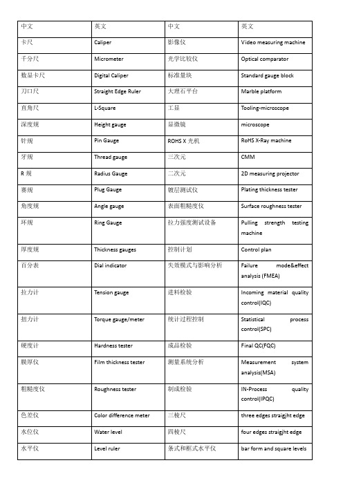
IN-Process quality control(IPQC)
色差仪
Color difference meter
三棱尺
three edges straigjht edge
水位仪
Water level
四棱尺
four edges straigjht edge
水平仪
Level ruler
条式和框式水平仪
数字高度测量仪
Digital height gauge
数据输入
Data input
表面处理仪器
Surface finish tester
轮廓记录器
Profile recorder
内/外径千分尺
Inside/outer micrometer
仪器的计量特性
Metrological characteristic of the instrument
接地电阻读数表
Earthing resistance reader
残余轮廓
residual profile
放大镜
Magnifying glass
触针式仪器
stylus instrument
铅锤
Plummet
感应位移数字存储触针式量仪
displacement sensitive,digitally storing stylus instrument
拾取单元
Tracing element
压力计
Pressure gauge
针尖
Stylus tip
电子卡尺
Digital caliper
转换器
transducer
深度千分尺
Depth gauge
超声测距相关毕业设计外文资料翻译

毕业设计(论文)外文资料翻译系(院):电子与电气工程学院专业:电气工程及其自动化姓名:学号:外文出处:United States Patent 5442592(用外文写)附件: 1.外文资料翻译译文;2.外文原文。
指导教师评语:签名:(手写签名)年月日注:请将该封面与附件装订成册。
外文资料翻译译文超声波测距仪文件类型和数目:美国专利5442592摘要:提出了一种可以抵消温度的影响和湿度的变化的新型超声波测距仪,包括测量单元和参考资料。
在每一个单位,重复的一系列脉冲的产生,每有一个重复率,直接关系到各自之间的距离,发射机和接收机。
该脉冲序列提供给各自的计数器,计数器的产出的比率,是用来确定被测量的距离。
出版日期:1995年8月15日主审查员:罗保.伊恩j.一、背景发明本发明涉及到仪器的测量距离,最主要的是,这种仪器,其中两点之间传输超声波。
精密机床必须校准。
在过去,这已经利用机械设备来完成,如卡钳,微米尺等。
不过,使用这种装置并不利于本身的自动化技术发展。
据了解,两点之间的距离可以通过测量两点之间的行波传播时间的决定。
这样的一个波浪型是一种超声波,或声波。
当超声波在两点之间通过时,两点之间的距离可以由波的速度乘以测量得到的在分离的两点中波中转的时间。
因此,本发明提供仪器利用超声波来精确测量两点之间的距离对象。
当任意两点之间的介质是空气时,声音的速度取决于温度和空气的相对湿度。
因此,它是进一步的研究对象,本次的发明,提供的是独立于温度和湿度的变化的新型仪器。
二、综述发明这项距离测量仪器发明是根据上述的一些条件和额外的一些基础原则完成的,其中包括一个参考单位和测量单位。
参考和测量单位是相同的,每个包括一个超声波发射机和一个接收机。
间隔发射器和接收器的参考值是一个固定的参考距离,而间距之间的发射机和接收机的测量单位是有最小距离来衡量的。
在每一个单位,发射器和接收器耦合的一个反馈回路,它会导致发射器产生超声脉冲,这是由接收器和接收到一个电脉冲然后被反馈到发射机转换,从而使重复系列脉冲的结果。
超声波测距report
基于AT89S52的超声波测距系统08级通信班巫文蔚摘要:本文介绍了AT89S52单片机的性能和特点,并在分析了超声波测距原理的基本上,指出了设计测距仪的思路和所需考虑的问题,给出了实现超声波测距方案的软、硬件设计系统框图。
该设计系统经校正后,其测量精度可达0.2米。
Abstract:This paper introduces the characteristics and properties of AT89S52 MCU, and analyzes the principle of basically ultrasonic ranging, points out the design ideas and rangefinder needed to consider the problem.This paper presents ultrasonic ranging scheme of software and hardware design of the system frame. The measurement precision can reach 0.2 meters via correction.超声波测距主要应用于倒车雷达、建筑施工工地以及一些工业现场,例如:液位、井深、管道长度等场合。
目前国内一般使用专用集成电路设计超声波测距仪,但是专用集成电路的成本很高,并且没有显示,操作使用很不方便。
本文介绍一种以AT89S52单片机为核心的低成本、高精度、微型化数字显示超声波测距仪的硬件电路和软件设计方法。
实际使用证明该仪器工作稳定,性能良好。
1 超声波测距原理超声波测距是通过不断检测超声波发射后遇到障碍物所反射的回波,从而测出发射和接收回波的时间差t,然后求出距离S=Ct/2,式中的C为超声波波速。
表1 声速与温度关系表由于超声波也是一种声波,其声速C与温度有关,表1列出了几种不同温度下的声速。
超声波测距系统外文文献翻译

=======大学本科生毕业设计外文文献及中文翻译文献题目: ULTRASONIC RANGING SYSTEM 文献出处: United States Patent译文题目:超声波测距系统学生:指导教师:专业班级:自动化11-4学号: 110601140416电气信息工程学院2014年5月1日超声波测距系统摘要超声波测距系统,是指选择性地激励一个变压器,使之产生换能器驱动信号。
超声换能器发射的超声波脉冲用于响应驱动信号然后接收到一个在超声波信号发出之后的回波信号。
分路开关接在变压器的绕组上,当超声波信号的传输在允许的近距离范围内达到一个稳定的等级,分路开关选择性的闭合来阻止蜂鸣器报警。
第1章发明背景像在宝丽来相机中应用的可用范围测试系统,它们都是准确而且可靠的,但都不适用于近距离测距,举个例子,2到3英寸的距离内就不适用,所以他们在9英寸甚至更远的距离测距是可靠的。
它们可以应用在很多的应用程序中,但不适用于可移动机器人领域内。
机器人通常必须通过门口只有两三英寸的间隙,如果当可移动机器人被操作于避障模式下通过狭小空间,可能机器人的规避路径过于狭窄,此外,规避动作应该使偏指定的路径距离最小化。
近距离测距不用于超声波系统的一个原因是,近距离输出脉冲输出太长以至于它重叠在回波脉冲上,即使输出脉冲缩短,输出脉冲仍然重叠回波脉冲,因为声音紧跟着输出脉冲。
备中产生的回波信号脉冲的范围为100毫伏,但设置传感器响应所必需的电路回声脉冲是大约150伏到300伏之间。
因此即使是最小的声波也会盖过回声信号。
事实上,dual-diode钳位电路用于将150伏降低到二极管的击穿电压,即0.7伏特。
但是这700毫伏足以盖过100毫伏的回波信号。
目前系统需要50毫秒将300伏特的峰值发射电压降到0.7伏特,且额外需要500到600毫秒的时间将它稳定在1毫伏范围。
第2章发明总结本发明可以提供一种改进的超声波测距系统。
本发明也可以提供一个改进的多通道超声波测距系统。
外文翻译正文

H8/300L超声波测距仪(原文出处:第1页-第15页)介绍该应用说明介绍了一种使用H8/38024 SLP MCU的测距仪。
由单片机产生40KHz 方波,通过超声波传感器发射出去。
反射的超声波被另外一个传感器接收。
有效距离为6cm到200cm。
1.理论1.1概况在这篇应用说明中,H8/38024F微处理器是作为目标设备被使用的。
由于简单的可移植性,超声波测距仪使用的软件为C语言。
超声波是频率高于可听音的一切高于20kHz的声波。
用于医疗诊断和影像的超声波,频率延长和超过了10兆赫兹,高的频率有短的波长,这使得超声波从物体反射回来更容易。
不幸的是,极高的频率难以产生和测量。
对超声波的检测与测量主要是通过压电式接收机进行的。
超音波普遍应用于防盗系统、运动探测器和车载测距仪。
其他应用包括医疗诊断(人体成像),清洁(去除油脂和污垢),流量计(利用多普勒效应),非破坏性试验(检测材料缺陷),焊接等各个方面。
1.2软件实施距离的计算要测量超声波传感器接收到回波的时间。
理想的被测对象应该有一个大的面积而且不吸收超声波。
在这个应用说明中使用了38024f的CPU电路板。
图1展示超声波测距仪的工作原理,tmofh (脚63 )是用来传送0.5ms的40kHz的超声波,irq0 ( pin72 ) 是用来探测反射波的。
发送超声波后,计时器C开始追踪Timer Counter C (TCC)的计数数目,以计算物体的距离。
图1.测距仪工作原理1.2.1 发射超声波定时器F是一个具有内置式输出比较功能16位计数器,它还可以用来作为两个独立的8位定时器FH和FL,这里,定时器F是作为两个独立的8位定时器使用。
计时器的FL被初始化为产生中断,而FH在比较匹配发生时触发了tmofh的输出电平。
表1 计时器F的时钟选择对于为定时器的FL,选定内部时钟ø/32。
输出比较寄存器FL装载数据初值为H’FF 。
因此,外部定时器每1.67msec 产生一个中断,计算如下:/2ø晶振频率=,计时器FL 内部时钟周期=322⨯晶振频率=64MHz 8304.9=153.6kHz 中断周期=256kHz6.1531⨯=1.67msec 每隔65msec 开始发射一次超声波,计时器FL 须中断近39次( 65msec / 1.67msec = 39 ),才开始传送。
测量工具中英文对照表

heodolite 经纬仪Water Level 水位仪Level Ruler 水平尺Casing gradienterCoating thickness Measurer 涂层测厚仪Ultrasonic thickness measurer 超声波测厚仪Ultrasonic crack detector 超声波裂纹测试仪Digital thermometer 数字温度计radiation thermometer 辐射温度计Gradient Reader 坡度读数器Electric spark leak hunter 电火花追踪器Volometer 万用表MegaOhmmeter 兆欧表Earthing resistance Reader 接地电阻读数表Plug gauge 圆柱塞规Magnifying glass 放大镜Plummet 铅锤Profile projector 投影仪Pin Gauge 针规(不知道和plug gauge 的区别在哪里,知道的请指正) Gauge block 块规Bore gauge 百分表A vernier caliper 游标卡尺Coordinate Measureing Machine(CMM) 三尺元Pressure gague寸压力计+电度厚度测试仪(Electroplating THK.Tester)转(扭)力仪(Twisting Meter)螺纹规(Thread Gauge)块规(Block Gauge)环规(Ring Gauge)力矩计(Torque Meter)塞规(Plug gage)高度仪(Altitude gauge)塞尺/间隙规(Clearance gauge)千分卡尺(Micrometer Calipers )“过” -- “不过”验规(通-止规) [go-no-go gauge] 游标卡尺(Vernier Caliper)电子卡尺(Digital caliper)深度千分尺(Depth Micrometer)销(针)规(Pin Gauge)投影仪(Projector )数字高度测量仪(Digital Height Gauge)表面处理测试仪(Surface Finish Tester)内/外径千分尺(Inside/outer Micrometer)洛(威)氏硬度仪[(HRC/HV) Hardness Tester)]温度计(Thermometer)孔规(Bore Gauge)电子称(Electric/digital Balance)三坐标测试仪 (CMM)万用表(Multimeter)1.刀口型直尺:knife straigjht edge2.刀口尺: knife straigjht edge3.三棱尺three edges straigjht edge4.四棱尺four edges straigjht edge5.条式和框式水平仪bar form and square levels6.合像水平仪 imaging level meter7铸铁平板 cast iron surface plate8.岩石平板 granite surface plate9.铸铁平尺cast iron straigjht edge10.钢平尺和岩石平尺steel and granite straigjht edge11.圆度仪 roundness measuring instrument12.电子水平仪electronic level meter13.表面粗糙度比较样块铸造表面 roughness comparison specimens cast surface14.表面粗糙度比较样块磨、车、铣、插及刨加工表面roughness comparison specimens-ground,turned,bored,milled,shape and planed15.表面粗糙度比较样块电火花加工表面roughness comparison specimens spark-erostion machining surfaces16.表面粗糙度比较样块抛光加工表面roughness comparison specimens pollshed surfaces17.接触式仪器的标称特性18.轮廓profiles19.轨迹轮廓 traced profile20.基准轮廓 reference profile21.总轮廓 total profile22.原始轮廓 primary profile23.残余轮廓residual profile24.触针式仪器stylus instrument25.感应位移数字存储触针式量仪displacement sensitive,digitally storing stylus instrument26.触针式仪器的部件stylus instrument components27.测量环measurement loop28.导向基准renfence guide29.驱动器drive unit30.测头(传感器)probe(pick-up)31.拾取单元tracing element32.针尖stylus tip33.转换器transducer34.放大器amplifier35.模/数转换器analog-to-digital converter36.数据输入data input37.数据输出data output38.轮廓滤波和评定profile filtering and evaluation39.轮廓记录器profile recorder40.仪器的计量特性metrological characteristics of the instrument41.静测力的变化change of static measuring force42.静态测力 static measuring force43.动态测量力 dynamic measuring force44.滞后hysteresis45.测头的测量范围 transmission function for the sine waves46.仪器的测量范围measuring range of the instrument47.模数转换器的量化步距quantization step of the ADC48.仪器分辨力 instrument resolution49.量程分辨力比range-to-resolution ratio50.测头线性偏差probe linearity deviation51.短波传输界限short-wave transmission limitation52.轮廓垂直成分传输 vertical profile component transmission53表面粗糙度比较样块抛丸、喷砂加工表面roughness comparison specimens shot blasted and blasted surfaces54产品结构几何量计术规范(GPS)geometrical product specifications(GPS)55表面结构 surface texture56接触式仪器的标称特性 nominal characteristics of contact instruments57公法线千分尺micrometer for mearsuring root tangent lenghths of gear teeth 58最大允许误差 maximum permissible error59圆柱直齿渐开线花键量规 gauges for straight cylindrical involute splines 60齿厚游标卡尺 Gear tooth verniercalipers61齿轮渐开线样板the involute master of gear62齿轮螺旋线样板 the helix master of gear63矩形花键量规 gauges for straight –sided splines64测量蜗杆 master worm65万能测齿仪 universal gear measuring instrument66万能渐开线检查仪universal involute measuring instrument67齿轮齿距测量仪gear circular pictch measuring instrument68万能齿轮测量机 Universal gear measuring machine69齿轮螺旋线测量仪gear helix measuring instrument70便携式齿轮齿距测量仪 manual gear circular pitch measuring instrument71便携式齿轮基节测量仪manual gear base pitch measuring instrument72立式滚刀测量仪vertical hob measuring instrument73齿轮双面啮合综合测量仪Gear dual-flank measuring instrument74齿轮单面啮合整体误差测量仪Gear single-flank meshing integrated error measuring instrument75梯形螺纹量规 gauges for metric trapezoidal screw threads76工作螺纹量规work gauges for metric trapezoidal screw threads77校对螺纹量规check gauges for metric trapezoidal screw threads78.梯形螺纹量规型式与尺寸 Types and dimensions of metric trapezoidal screw threads79.普通螺纹量规型式与尺寸 Types and dimensions of gauges purpose screw threads80.非螺纹密封的管螺纹量规 Gauges for pipe threads prcessure-tight joints are not made on the threads81.螺纹千分尺Screw thread micrometer82.最大允许误差 maximum permissible error83.间隙螺纹量规 Clearance screw gauge84.量针Bar gauge85.螺纹样板 Screw thread template86.用螺纹密封的管螺纹量规Gauges for pipe threads where pressure-tight joints are made on the threads87.刀具预调测量仪? 精度Accuracy of the presetting instrument88.薄膜式气动量仪Membrane type pneumatic measuring instrument89.光栅线位移测量系统Grating linear displacement measuring system90.光栅角位移测量系统Grating angular displacement measuring system91.磁栅线位移测量系统Magnet-grid linear displacement measuring system92.量块附件Accessories for gauge blocks93.V形架Vee blocks94.比较仪座Comparator stand95.磁性表座Magnetic stand96.万能表座Universal stand for dial indicator一般术语:1.几何量 geometrical product2.量值value(of a quantity)3.真值true value(of a quantity)4.约定真值 conventional true value(of a quantity)5.单位unit(of measurement)6.测量measurement7.测试measurement and test8.检验inspecte9.静态测量static measurement10.动态测量dynamic measurement11.测量原理principle of measurement12.测量方法method of measurement13.测量程序measurement procedure14.被测量measurand15.影响量influence quantity16.变换值transformed value(of a measurand)17.测量信号measurement signal18.直接测量法direct method of measurement19.间接测量法indirect method of measurement20.定义测量法definitive method of measurement21.直接比较测量法direct-comparison method of measurement22.替代测量法substitution method of measurement23.微差测量法differential method of measurement24.零位测量法nulll method of measurement25.测量结果result of a measurement26.测得值measured value27.实际值actual value28.未修正结果uncorrected result (of a measurement)29.已修正结果corrected result(of a measurement)30.测量的准确度accuracy of measurement31.测量的重复性repeatability of measurement32.测量复现性reproducibility of measurements33.实验标准偏差experimental standard deviation34.测量不确定度uncertainty of measurement35.测量绝对误差 absolute error of measurement36.相对误差 relative error37.随机误差random error38.系统误差 systematic error39.修正值correction40.修正系数correction factor41.人员误差personal error42.环境误差environmental error43.方法误差error of method44.调整误差adjustment error45.读数误差reading error46.视差parallax error47.估读误差 interpolation error48.粗大误差parasitic error49.检定verification50.校准calibration51.调准gauging52.调整adjustment几何量测量器具术语1.几何量具测量器具dimensional measuring instruments2.长度测量器具length measuring instruments3.角度测量器具angle measuring instruments4.坐标测量机coordinate measuring machine5.形状和位置误差测量器具form and position error measuring instruments6.表面质量测量器具surface quality measuring instruments7.齿轮测量器具gear measuring instruments8.实物量具(简称“量具”)material measure9.测量仪器(简称“量仪”)measuring instruments10.测量链measuring chain11.测量装置measuring system12.指示式测量仪器indicating(measuring )instrument13.记录式测量仪器recording(measuring)instrument14.累计式测量仪器totalizing(measuring)instrument15.积分式测量仪器integrating(measuring)instrument16.模拟式测量仪器analogue(measuring)instrument17.数字式测量仪器digital(measuring)instrument18.测量变换器measuring transducer19.传感器sensor20.指示装置indicating device21.记录装置recording device22.记录载体recording medium23.标尺标记scale mark24.指示器index25.标尺scale26.度盘dail测量器具术语1.标称值nominal value2.示值indication(of a measuring instrument)3.标尺范围scale range4.标称范围nominal range5.标尺长度scale length6.标尺分度scale division7.分度值value of a scale division8.标尺间距scale spacing9.线性标尺linear scale10.非线性标尺non-linear scale11.标尺标数scale numbering12.测量仪器的零位zero of a measuring instrument13.量程span14.测量范围measuring range15.额定工作条件vated operating conditions16.极限条件reference condition17.标准条件reference condition18.仪器常数instrument constant19.响应特性response characteristic20.灵敏度senstivity21.鉴别力discrimination22.分辨力resolution(of an indicating device)23.死区dead band24.准确度accuracy of a measuring instruments25.准确度等级accuracy class26.重复性repeatability of a measuring instrument27.示值变动性varation of indication28.稳定度stability29.可靠性reliability30.回程hysteresis31.漂移drift32.响应时间response time33.测量力(简称“测力”)measuring force测量器具术语1.实物量具示值误差error of indication of a material measure2.测量仪器示值误差error of indication of a measuring instrument3.重复性误差repeatability error of a measuring instrument4.回程误差hysteresis error5.测量力变化variation of measuring force6.测量力落差hysteresis of measuring force7.偏移误差bias error (of a measuring instrument)8.允许误差maximum permissible errors(of measuring instruments)9.跟踪误差tracking error (of a measuring instrument)10.响应率误差response-law error (of a measuring instrument)11.量化误差quantization error (of a measuring instrument)12.基值误差datum error (of a measuring instrument)13.零值误差zero error (of a measuring instrument)14.影响误差influence error15.引用误差fiducial error16.位置误差position error17.线性误差linear error18.响应特性曲线response characteristic curve19.误差曲线error curve20.校准曲线calibration curve21.修正曲线correction curve长度测量器具量具类1.量块gauge block2.光滑极限量规plain limit gauge3.塞规plug gauge4.环规ring gauge卡规snap gauge5.塞尺feeler gauge6.钢直尺steel gauge7.精密玻璃线纹尺precision glass linear scale8.精密金属线纹尺precision metal linear scale9.半径样板radius template卡尺类1.游标卡尺vernier caliper2.带表卡尺dial caliper3.电子数显卡尺calliper with electronic digital display4.深度标游卡尺depth vernier caliper5.电子数显深度卡尺depth caliper with electronic digital display6.带表高度卡尺dial height calliper7.高度游标卡尺height vernier caliper8.电子数显高度卡尺height caliper with electronic digital display9.焊接检验尺calliper for welding inspection千分尺类1.测微头micrometer head2.外径千分尺external micrometer3.杠杆千分尺micrometer with dial comparator4.带计数器千分尺micrometer with counter5.电子数显外径千分尺micrometer with electronic digital display6.小测头千分尺small anvil micrometer7.尖头千分尺point micrometer8.板厚千分尺sheet metal micrometer9.壁厚千分尺tube micrometer10.叶片千分尺blade micrometer11.奇数沟千分尺odd fluted micrometer12.深度千分尺depth micrometer13.内径千分尺internal micrometer14.单杆式内径千分尺single-body internal micrometer15.表式内径千分尺 dail internal micrometer16.三爪式内径千分尺three point internal micrometer17.电子数显三爪式内径千分尺three point internal micrometer18.内测千分尺inside micrometer指示表类1.指示表 dial indicator2.深度指示表depth dial indicator3.杠杆指示表dial test indicator4.内径指示表bore dial indicator5.涨弹簧式指示表 expanding head bore dial indicator6.钢球式内径指示表ball type bore dial indicator7.电子数显指示表dial indicator with electronic digital display8.杠杆卡规indicating snap gauge9.带表卡规dial snap gauge10.带表外卡规outside dial snap gauge11.带表内卡规inside dial snap gauge12.测厚规thickness gauge13.扭簧比较仪microcator14.杠杆齿轮比较仪mechanical dial comparator15.电子量规electronic gauge16.电感式传感器inductance type transducer17.指示装置indicating device18.电感测微仪inductance micrometer19.峰值电感测微仪peak inductance micrometer20.电感内径比较仪inductance bore comparator21.瞄准传感器aiming transducer角度测量器具1.角度块angle block gauge2.正多面棱体regular polygon mirror3.刀具角度样板cutter angular template4.直角尺square5.平行直角尺parallel square6.宽座直角尺wide-stand square7.刀口形直角尺edge square8.矩形直角尺square square9.三角形直角尺three angle square10.圆柱直角尺cylinder square11.方形角尺square guage12.万能角度尺universal bevel protractor13.游标式万能角度尺vernier universal bevel protractor14.表式万能角度尺dial universal bevel protractor15.光学分度头optical dividing head16.目镜式光学分度头optical dividing head with microscope reading17.投影式光学分度尺optical dividing head with projection reading18.光电分度头optical-electronic dividing head19.多齿分度台multi-tooth division table20.分度转台division rotary table21.正炫规sine bar22.普通正炫规general sine bar23.铰链式正炫规hinge type sine bar24.双向正炫规dual-directional sine bar25.圆锥量规cone gauge26.圆锥塞规plug cone gauge27.圆锥环规ring cone gauge28.直角尺测量仪square measuring instrument形位误差测量器具1.平晶optical flat2.单面平晶optical flat3.双面平晶parallel optical flat4.刀口形直尺knife straight edge5.刀口尺knife straight edge6.三棱尺three edges straight edge7.四棱尺four edges straight edge8.平尺straight edge9.矩形平尺square straight edge10.工字形平尺i-beam straight edge11.角形平尺angle straight edge12.桥形平尺bridge type straight edge13.平板surface plate14.铸铁平板cast iron surface plate15.岩石平板granite surface plate16.方箱square box17.水准器式水平仪level meter18.条式水平仪bar level meter19.框式水平仪frame level meter20.合像水平仪imaging level meter21.光学倾斜仪optical inclinometer22.电子水平仪electronic level meter23.指针式电子水平仪electronic level meter with indicator24.数显式电子水平仪electronic level meter with digital display25.平直度测量仪straightness measuring instrument26.光学式平直度测量仪optical straightness measuring instrument27.光电式平直度测量仪photoelectrical straightness measuring instrument28.圆度测量仪roundness measuring instrument29.转轴式圆度测量仪spindle-rotating type roundness measuring instrument30.转台式圆度测量仪table-rotating type roundness measuring instrument表面质量测量器具表面粗糙度比较样块surface roughness comparison specimen铸造表面粗糙度比较样块surface roughness comparison specimen for cast surface磨、车、镗、铣、插及刨加工表面粗糙度比较样块surface roughness comparison specimen for ground,turned,bored,milled,shaped and planed surface电火花加工表面粗糙度比较样块surface roughness comparison specimen for spark-erosion machined surface抛(喷)丸、喷砂加工表面粗糙度比较样块surface roughness comparison specimen for shot blasted and grit blasted surface抛光加工表面粗糙度测量仪portable surface roughness comparison specimen for polished surface便携式表面粗糙度测量仪portable surface roughess measuring instrument驱动箱driving box台式表面粗糙度测量仪bench type surface roughness measuring instrumentNose bridge 鼻中 Tip 脚套Temple 脚丝 Plating 电镀Printing 印字 Lase 镭射Spectacle frames 眼镜架 Sunglasses 太阳眼镜Sports spectacles 运动眼镜 kid's eyewear 儿童眼镜Reading glasses 老花镜 Contact lens 隐形眼镜Glass optical lenses 玻璃镜片 Plastic optical lenses 塑胶镜片Sunglasses lenses, sun clips 太阳镜片、镜夹 Progressive lenses 渐进多焦点镜片Photochromic lenses 变色镜片 Othro k lenses 角膜矫形接确镜片Optical blanks 镜片毛胚 Accessories for contact lens 隐形眼镜附件Spectacle spare parts and accessories 眼镜零件及配件 Components of frames 镜架组件Spectacle cases & accessories 眼镜盒及附件 Eyecare products and solution for lenses and contace lenses 眼睛护理产品及隐形眼镜洁液Spectacle cases & accessories 眼镜盒及其它配件 Lens demisting cloths and solutions 镜片除雾喷剂及清洁布Spectacle assembling & adjusting tools 眼镜加工、装配、调较工具 Visual test equipment 验眼设备Edger 磨边机 Eyeglasses and frame making machinery 眼镜架制造机械Lens manufacturing and processing machinery 镜片造机械及加工机械 Contact lensprocessing machinery 隐形眼镜加工机械Lathe 车床 Coating machine 镀膜机Coating materials 镀膜原料 Electroplating equipment, welding machine 电镀机械、焊接机械Price labeling, stamp printing and screen printing mahcinery 标签机、移印机、丝网印刷 Ultrasonic cleaning equipment 超声波清洁仪器Ophthalmic products 眼科用品 Concentrates for ultrasonic cleaning 超声波清洁剂Lens grinding and polishing filtration systems 镜片研磨及抛光过滤系统 Optical processing equipmentand materials 光学加工设备及原料Measurement instrucments for optical elements and systems 光学用品及系统之测量仪器 Store and workshop fitting and furniture 眼镜店及工场设备及家具Moulds for ophthalmic lenses 镜片模具 Raw materials for frames 眼镜原料Raw materials for lenses 镜片原料 Lens abrasive and polishing materials 打磨镜片原料Electroplating, welding materials 电镀、焊接原材料Opto-laser equipment and instruments 激光科技设备和仪器机械英语单词冲床punching machine机械手robot油压机hydraulic machine车床 lathe刨床planer |'plein?|铣床miller磨床grinder(钻床)driller线切割linear cutting金属切削 metal cutting机床 machine tool金属工艺学 technology of metals刀具 cutter摩擦 friction联结 link传动 drive/transmission轴 shaft弹性 elasticity频率特性 frequency characteristic误差 error响应 response定位 allocation机床夹具 jig动力学 dynamic运动学 kinematic静力学 static分析力学 analyse mechanics拉伸 pulling压缩 hitting剪切 shear扭转 twist弯曲应力 bending stress强度 intensity三相交流电 three-phase AC磁路 magnetic circles 变压器 transformer异步电动机 asynchronous motor几何形状 geometrical精度 precision正弦形的 sinusoid交流电路 AC circuit机械加工余量 machining allowance变形力 deforming force变形 deformation应力 stress硬度 rigidity热处理 heat treatment退火 anneal正火 normalizing脱碳 decarburization渗碳 carburization电路 circuit半导体元件 semiconductor element反馈 feedback发生器 generator直流电源 DC electrical source门电路 gate circuit逻辑代数 logic algebra外圆磨削 external grinding内圆磨削 internal grinding平面磨削 plane grinding变速箱 gearbox离合器 clutch绞孔 fraising绞刀 reamer螺纹加工 thread processing螺钉 screw铣削 mill铣刀 milling cutter功率 power工件 workpiece齿轮加工 gear mechining齿轮 gear主运动 main movement主运动方向 direction of main movement进给方向 direction of feed进给运动 feed movement合成进给运动 resultant movement of feed合成切削运动 resultant movement of cutting合成切削运动方向 direction of resultant movement of cutting 切削深度 cutting depth前刀面 rake face刀尖 nose of tool前角 rake angle后角 clearance angle龙门刨削 planing主轴 spindle主轴箱 headstock卡盘 chuck加工中心 machining center车刀 lathe tool车床 lathe钻削镗削 bore车削 turning磨床 grinder基准 benchmark钳工 locksmith锻 forge压模 stamping焊 weld拉床 broaching machine拉孔 broaching装配 assembling铸造 found流体动力学 fluid dynamics流体力学 fluid mechanics加工 machining液压 hydraulic pressure切线 tangent机电一体化 mechanotronics mechanical-electrical integration 气压 air pressure pneumatic pressure稳定性 stability介质 medium液压驱动泵 fluid clutch液压泵 hydraulic pump阀门 valve失效 invalidation强度 intensity载荷 load应力 stress安全系数 safty factor可靠性 reliability螺纹 thread螺旋 helix键 spline销 pin滚动轴承 rolling bearing滑动轴承 sliding bearing弹簧 spring制动器 arrester brake十字结联轴节 crosshead联轴器 coupling链 chain皮带 strap精加工 finish machining粗加工 rough machining变速箱体 gearbox casing腐蚀 rust氧化 oxidation磨损 wear耐用度 durability随机信号 random signal离散信号 discrete signal超声传感器 ultrasonic sensor集成电路 integrate circuit挡板 orifice plate残余应力 residual stress套筒 sleeve扭力 torsion冷加工 cold machining电动机 electromotor汽缸 cylinder过盈配合 interference fit热加工 hotwork摄像头 CCD camera倒角 rounding chamfer优化设计 optimal design工业造型设计 industrial moulding design 有限元 finite element滚齿 hobbing插齿 gear shaping伺服电机 actuating motor铣床 milling machine钻床 drill machine镗床 boring machine步进电机 stepper motor丝杠 screw rod导轨 lead rail组件 subassembly可编程序逻辑控制器 Programmable Logic Controller PLC 电火花加工 electric spark machining电火花线切割加工 electrical discharge wire - cutting 相图 phase diagram热处理 heat treatment固态相变 solid state phase changes有色金属 nonferrous metal陶瓷 ceramics合成纤维 synthetic fibre电化学腐蚀 electrochemical corrosion车架 automotive chassis悬架 suspension转向器 redirector变速器 speed changer板料冲压 sheet metal parts孔加工 spot facing machining车间 workshop工程技术人员 engineer气动夹紧 pneuma lock数学模型 mathematical model画法几何 descriptive geometry机械制图 Mechanical drawing投影 projection视图 view剖视图 profile chart标准件 standard component零件图 part drawing装配图 assembly drawing尺寸标注 size marking技术要求 technical requirements刚度 rigidity内力 internal force位移 displacement截面 section疲劳极限 fatigue limit断裂 fracture塑性变形 plastic distortion脆性材料 brittleness material刚度准则 rigidity criterion垫圈 washer垫片 spacer直齿圆柱齿轮 straight toothed spur gear斜齿圆柱齿轮 helical-spur gear直齿锥齿轮 straight bevel gear运动简图 kinematic sketch齿轮齿条 pinion and rack蜗杆蜗轮 worm and worm gear虚约束 passive constraint曲柄 crank摇杆 racker凸轮 cams范成法 generation method毛坯 rough游标卡尺 slide caliper千分尺 micrometer calipers攻丝 tap光学仪器类△Topslit illumination 裂隙灯 diopter 屈光度 sphere 球镜cylinder 柱镜 prism 棱镜 magnification 放大倍率diameter 直径 dimensions 尺寸 light spot 光斑fixation lamp 固视灯 led 发光二极管 filter 滤色片lensmeter 焦度计 metal rim 金属圈 PD meter 瞳距仪Pupil Distance 瞳距 Vertex Distance 顶点距 Chart 视标View tester 验光仪 Cutting device 切割刀 Pattern maker 制模机Cutting needle 划针 Layout blocker 中心仪 Hand edger 手动磨边机Lens groover 开槽机 Polisher 抛光机 Polishing stick 抛光膏Drilling machine 钻孔机 Bench drilling machine 台式钻孔机 Drill bit 钻头Lock opener 锁开 Milling cutting 铣刀 Fuse 保险丝Handle 手柄 Center locator 中心定位器 Drill chuck 钻夹头Dial 刻度盘 Frame heater(warmer)烘架机 Heating coil 发热丝Ultrasonic cleaner 清洗机 Combined table 验光组合台 Optometry box 验光盘Grinding wheel 砂轮 Trial lens set 验光镜片箱 Refractometer 验光仪Chart projector 投影仪 Keratometer 角膜曲率仪 Welding machine 焊接机Spray cleaning machine 喷淋清洗机材料配件类△TopMonel 锰料 Stainless Steel 不锈钢 pure Titanium 纯钛Titanium Alloy 钛合金 B-Ti B钛 Elongation 伸长率Tensile strenghth 抗拉强度 high nickel copper alloy 高镍合金 nickelfree alloy 无镍合金nicklfree stainless steel 无镍不锈钢 annealing temperture 退火温度 percent 含量density 密度 melting point 熔点 solidus 固相点liquidus 液相点 physical properties 物理性能 chemical composition 化学组成hinge 铰链 rim wire 框线 round wire 圆线cylinding grinding wheels 筒形砂轮 flaring cup wheels 碗形砂轮 diamod plain wheels 平形砂轮grinding ccoolant 切削液 lens coating liquid 护镜液 polishing powder 抛光粉polishing liquid 抛光液 polishing wheel 抛光轮 plating case 电镀盒plastic case 塑料盒 alumium oxide case 氧化铝盒 rocket screwdrivers 六角螺丝刀mini ring wrenches/nutdrivers 微型戒指扳手radian apparatus 弧度表thickness apparatus 厚度表adhesive tape 粘片 calipers 量具 nut driver 套筒files set 锉刀 drill bits 钻咀 screwdrivers blades 螺丝刀头镜片类△Tophard resin lens 树脂镜片 round-top bifocal lens 圆顶双关镜片 flat-top bifocal lens 平顶双光镜片aspheric hard resin lens 非球面树脂镜片 Non-coated lens 基片(NC) hard coated lens 加硬镜片(HC)Hard & Multi-coated 加硬加膜片(HMC) Hard & Multi-coated,EMI Defending Coating 加硬加膜防辐射片(HMC+EMI) RX Lens-High Index 高散光片color shade 色差 deformation 变形 shrinkage 缩水light transmission 透光率 de-lamination 分裂脱层 abbe value 阿贝数raw material 原材料 catalysis 催化作用 polymerization 聚合作用tinted lens 染色镜片 photochromic lens 变色镜片 spherical 球面的autocollimator 自动准直机bench comparator 比长仪block gauge 块规bore check 精密小测定器calibration 校准caliper gauge 卡规check gauge 校对规clearance gauge 间隙规clinoretee 测斜仪comparator 比测仪cylinder square 圆筒直尺depth gauge 测深规dial indicator 针盘指示表dial snap gauge 卡规digital micrometer 数位式测微计feeler gauge 测隙规gauge plate 量规定位板height gauge 测高规inside calipers 内卡钳inside micrometer 内分测微计interferometer 干涉仪leveling block 平台limit gauge 限规micrometer 测微计mil 千分之一寸monometer 压力计morse taper gauge 莫氏锥度量规nonius 游标卡尺optical flat 光学平晶optical parallel 光学平行passimeter 内径仪position scale 位置刻度profile projector 轮廓光学投影仪protractor 分角器radius 半径ring gauge 环规sine bar 正弦量规snap gauge 卡模square master 直角尺stylus 触针telescopic gauge 伸缩性量规working gauge 工作量规。
高精度超声波测距系统英文原文

High-precision Ultrasonic Ranging SystemAbstractThe ultrasound is easy to transmit and has good reflection. Its speed is far less than the speed of flight. So this paper designs an ultrasonic ranging system based on STC89C52RC. This system can be effective in the range of about372 cm. After repeated test, the measurement error can be less than 1 cm. So this system can be applied to intelligent avoidanceand vehicle transportation and other systems.Key words: SCM; ultrasound; send; receive; ranging;temperature compensationI. INTRODUCTIONAt present, the main methods of ultrasonic ranging include pulse-echo method, phase modulation, frequency modulation and FFT-based approach. In these methods, the pulse-echo method has good adaptability; this method not only can be used for manual testing, but also combined with the automated systems. So it is most widely used at home and aboard.Nowadays, the theories of microwave and laser ranging have been applied to the ultrasonic ranging system. It can be a very good research. On the other hand, the filtering and analysis of the echo can also draw more and more attention of many experts and scholars. With the enhanced understanding of the ultrasonic theory, we know how to improve the precision and the anti-jamming capabilities will be the most the important performance indicators.In this paper, the pulse-echo theory is used to design the entire system. The following content is mainly divided into three parts. The first section describes the hardware architecture of the system. The second part describes the software processing of the system. The third section describes the techniques of data processing. Insuch a case, the reader can have a comprehensive understanding of the system.II.THE PRINCIPLE OF ULTRASONIC RANGING SYSTEM Considering the requirement of the actual project, we choose the ultrasound, the frequency of which is 40 kHz. Ultrasonic sensor is this kind device which can converse the sound and the electrical power, also known as ultrasonic transducer or ultrasonic probe. In certain frequency range, it can convert the electrical signal to the external ultrasonic signal or change the external ultrasonic signal to the electricalsignal. In this paper, we choose the T/R40-12 piezoelectric ultrasonic transducer. It works at the frequency of 40 kHz. Its external diameter is 12cm.Ultrasonic generator sends the ultrasonic signal at a certain time. After the ultrasonic signal reflected from the measured object, the ultrasonic receiver can receive the signal. As long as we record the time between the sending time and the receiving time, we can calculate the distance from the ultrasonic sender to the measured object. The formula for calculating the distance is:D = S/2 = V ×T /2 (1)D is the distance between the ranging device and the measured object. S is the distance which the ultrasound transports. V is the speed of the ultrasound. T is the time which the ultrasound transports. Because ultrasound is also a kind of sound wave, the speed can be affected by the temperature. So in this paper, it uses the method of temperature compensation to improve the accuracy of the system.III.HARDWARE OF THE SYSTEMThe system block diagram of ultrasonic ranging system is fig. 1. The hardware mainly includes the SCM system, the display circuit, the temperature compensation circuit and the circuit of sending and receiving ultrasound.Fig.1 The block diagram of this systemA.The circuit of sending ultrasoundThe schematic of sending ultrasound is the figure 2. The sending circuit mainly includes the inverter and the ultrasonic transducer. At first the port P1.0 of SCM is inverted, connected to one pole of the ultrasonic transducer, and then inverted again, connected to another pole of the ultrasonic transducer. By means of this push-pull method, we can improve the emission intensity of the ultrasound. Paralleling the inverter; we can increase the driving capability of outputting. The pull-up resistor R1 and R2 not only increases the driving capability of outputting the high level, but alsoincreases the damping effect of the ultrasonic transducer and shorten the time of its free oscillations.Fig.2 The circuit of sending ultrasoundB. The circuit of receiving ultrasoundThe schematic of receiving ultrasound is the fig. 3.ASIC CX20106 is used for detecting infrared.Considering the carrying frequency of CX20106 is 38kz which is very close to the frequency of the ultrasound, we design the receiving circuit by making use of CX20106.Fig.3 The circuit of receiving ultrasoundC. SCM system and the display circuitSCM STC89C52RC is the core of this ranging system, by using the 12MHz crystal oscillator to obtain a more stable clock frequency and reduce the errors. The port P1.0 of the SCM output the 40 KHz square wave that is required by the ultrasonic transducer. The external interrupt 0 is used to monitor the returning signal. The simple and practical four bit common anode LED is used for the display circuit. The segment code is driven by 74LS245, and the bit code is driven by the transistor 9012. It is shown in fig. 4.Fig.4 SCM system and the display circuitD. The circuit of temperature compensationIn the ultrasonic ranging system, a good many factors can affect the speed, such as the environmental interference, the frequency of the base pulse, etc. But the environmental temperature can be the main factor. According to the formula (2), we can see that the temperature varies from 0 ℃to 40℃, the speed of ultrasound varies from 331.4m/s to 354.85m/s. Take the room temperature 20 as the base, the speed is 343.32m/s and the rate of change is 6.83%. So the temperature factor can not be ignored. In the summer, the temperature is often more than 40 . So in the ultrasonic ranging system, it is necessary to have the temperature compensation in order to reduce the error. Nowadays most of the temperature monitoring system takes the method of temperature sensor. First of all, we convert the temperature signal to the electric signal, secondly amplify the electric signal, and thirdly convert the analog signal to the digital signal by the A/D converter. This kind of circuit is very complex and can be easily affected by the parameters of the components. For these reasons, this paper uses the temperature sensor DS18B20 and SCM to design this precisiontemperature measurement system. It can increase the accuracy of the measurement to some extent. The port DQ of the DS18B20 can directly be connected to the port P3.7 of the SCM. The circuit is shown in fig. 5.Fig.5 The circuit of temperature compensationDS18B20 is the latest digital temperature sensor from America. It is different from the traditional thermistor temperature sensors. We can directly read the measured temperature values. According to the actual requirements, we can realize the 9 or 10 bit A/D conversion through simple programming. As a result, DS18B20 can make the system has a simpler structure and higher reliability. After measuring temperature, we correct the speed of the ultrasound by the following formula: V (T) = (331.05+0.607T) (m/s) (2)In the above formula, T is the Celsius temperature of the environment ( ℃ ). IV. SYSTEM PROGRAMMINGThe programming of the ultrasonic ranging system mainly include the main program, sending subroutine, receiving subroutine, temperature compensation subroutine and display subroutine. On one hand, the assembly language is efficient and easy. On the other hand, the ranging program not only need complex calculation, but also requires a highly accurate result. So we choose assembly language to design this system.A.The main programThe main program firstly initialize the system environment, set the T0 timer for the 16-bit timer mode, Secondly set the general interrupt enable bit EA, then initialize the display port P0 and P2. After measuring the temperature value by making use of the DS18B20, the temperature compensation subroutine modifies the sound speed. At this time, it begins to call the sending subroutine. In order to avoid the direct transmission from the transmitter to the receiver, It need a delay of about 0.1ms (this is the reason for the minimum distance can be measured), then enable the external interrupt 0 to receive the return signal. As a result of using the 12MHz crystal oscillator, the timer increase one, the interval is 1us, when the main program detects that the flag is successful, it start to calculate the distance according to the timer T0, the result will be sent for LED display. Then just repeat this processing. The main program flow chart is shown in fig.6.Fig.6 The flow chart of the main programB. Sending subroutine and receiving subroutineThe sending subroutine is the role of sending about 2 ultrasonic pulses through port P1.0 (about 40kHz square wave), the pulse width is about 12us. At the same time, the timer T0 starts timing. This system makes use of the external interrupt 0 to detect the echo. Once received the echo (the pin INT0 appears a low level), it immediately access to the interrupt program, then stop the timer T0 and set the successful flag. If the echo has not been detected when the timer overflow, the timer T0 overflow interrupt will close the external interrupt 0. At the same time, it clears the successful flag. It means that this ranging processing is unsuccessful.C. Temperature compensation subroutine and display subroutineAccording to the real-time temperature detected, it calculates the speed of sound by substituting the formula (2). Display program shows the distance in the way of look-up table.V.DATA PROCESSINGNot only the processing that the circuit deal with the signal will produce a fixed delay t, but also the processing that SCM collect the signal will produce a fixed delay t. Both the above process certainly lead to some measurement errors, But this system modify the delay to reduce the ranging error. Suppose that S1 and S2 are two fixed distance. t1 and t2 are corresponding to the two fixed distance respectively(including the t factor). So S1 and S2 are actually corresponding to the time t1- t and t2- t. That is S1=0.5V(t1- t),S2=0.5V(t2- t),it can be calculated:After several measurements, we can calculate the system delay t. According to the formula (1), we can determine the distance measured. This processing can reduce the system error to some extent.VI. ACTUAL MEASUREMENT AND ANALYSISThe measurement data is shown in table 7.Table 7.The actual measurement data (unit: cm)The experimental data show that: the blind spot of the ultrasonic ranging system (the least distance that the ultrasonic sensors can detect) is 25cm. The largest distance is 372cm. While designing the program, to avoid the direct transmission of the ultrasound from the transmitter to the receiver, the program has a delay about 1.4ms, so the ultrasonic ranging system has a least ranging distance. Because the propagation of the ultrasound may cause a certain decay and the transmit power is limited, it is difficult to detect the long-rang echo. So there will be a largest measurable distance. On the other side, the temperature compensation can improve the accuracy of the measurement.VII. CONCLUSIONIn this paper, it makes use of the reflection characteristics of ultrasound. We design this kind of ranging system based on STC89C52RC. Its effective range is from 25cm to 372cm by means of non-contact measurement. Once the environment temperature changes, it improves the measurement accuracy of the system by temperature compensation circuit. After modifying the system delay, it can reduce the system latency measurement error and have a significantly improved accuracy. The results validate the rationality of the system including both the hardware and the software. This ranging system is reliable and stable. It is fully able to meet a number of high-precision occasions, such as level measurement, robot positioning, etc. ACKNOWLEDGMENTFirst of all, I thank the IEEE for providing this template, secondly I want to thank my instructor Mr. Guo, last but not least, We sincerely thank all colleagues who previously provided technical support.REFERENCES[1] WANG AI ZH. Design and reality of ultrasonic ranging system base on the microcontroller[J]. Journal of Xinzhou Teachers University, 2010,26(2): 44-46. [2] KANG Y P, LIU ZH Y, GUO X, et al. Design of high-precision ultrasonic wave ranging system[J]. Experimental Technology and Management, 2010, 27(3): 61-64. [3] WANG ZH J, SU X Y, HAN Y P. Ultrasonic distance measurement system with high precision based on AT89C51 microprocessor[J]. Sensor Technology & Applocation, 2010(1): 21-24.[4] HAN L R. A survey of methods for improving ultrasonic ranging precision[J]. Telecommunication Engineering, 2010, 50(9): 132-136.。
- 1、下载文档前请自行甄别文档内容的完整性,平台不提供额外的编辑、内容补充、找答案等附加服务。
- 2、"仅部分预览"的文档,不可在线预览部分如存在完整性等问题,可反馈申请退款(可完整预览的文档不适用该条件!)。
- 3、如文档侵犯您的权益,请联系客服反馈,我们会尽快为您处理(人工客服工作时间:9:00-18:30)。
H8/300L超声波测距仪(原文出处:第1页-第15页)介绍该应用说明介绍了一种使用H8/38024 SLP MCU的测距仪。
由单片机产生40KHz 方波,通过超声波传感器发射出去。
反射的超声波被另外一个传感器接收。
有效距离为6cm到200cm。
1.理论1.1概况在这篇应用说明中,H8/38024F微处理器是作为目标设备被使用的。
由于简单的可移植性,超声波测距仪使用的软件为C语言。
超声波是频率高于可听音的一切高于20kHz的声波。
用于医疗诊断和影像的超声波,频率延长和超过了10兆赫兹,高的频率有短的波长,这使得超声波从物体反射回来更容易。
不幸的是,极高的频率难以产生和测量。
对超声波的检测与测量主要是通过压电式接收机进行的。
超音波普遍应用于防盗系统、运动探测器和车载测距仪。
其他应用包括医疗诊断(人体成像),清洁(去除油脂和污垢),流量计(利用多普勒效应),非破坏性试验(检测材料缺陷),焊接等各个方面。
1.2软件实施距离的计算要测量超声波传感器接收到回波的时间。
理想的被测对象应该有一个大的面积而且不吸收超声波。
在这个应用说明中使用了38024f的CPU电路板。
图1展示超声波测距仪的工作原理,tmofh (脚63 )是用来传送0.5ms的40kHz的超声波,irq0 ( pin72 ) 是用来探测反射波的。
发送超声波后,计时器C开始追踪Timer Counter C (TCC)的计数数目,以计算物体的距离。
图1.测距仪工作原理1.2.1 发射超声波定时器F是一个具有内置式输出比较功能16位计数器,它还可以用来作为两个独立的8位定时器FH和FL,这里,定时器F是作为两个独立的8位定时器使用。
计时器的FL被初始化为产生中断,而FH在比较匹配发生时触发了tmofh的输出电平。
表1 计时器F的时钟选择对于为定时器的FL,选定内部时钟ø/32。
输出比较寄存器FL装载数据初值为H’FF 。
因此,外部定时器每1.67msec 产生一个中断,计算如下:/2ø晶振频率=,计时器FL 内部时钟周期=322⨯晶振频率=64MHz 8304.9=153.6kHz 中断周期=256kHz6.1531⨯=1.67msec 每隔65msec 开始发射一次超声波,计时器FL 须中断近39次( 65msec / 1.67msec = 39 ),才开始传送。
表2 功能选择FH 产生40kHz 的超声波信号,当计数FH (TCFH)的值达到输出比较寄存器FH(OCRFH)的值时,TMOFH 被触发,输出比较寄存器FH 的值如下计算。
FH 内部时钟选择为ø/4。
计时器FH 内部时钟周期=421⨯晶振频率=MHz8304.98=0.814μsec ,对于40kHz 信号,TMOFH 需要每12.5μs 触发一次:(1/40kHz)/2输出比较寄存器FH(OCRFH):OCRFH=sec814.0sec 5.12μμ=15.36≈15 因此, 0CRFH 装载H'0F 。
.软件的延时是用来在把63管脚转换成I/O 口P32以停止发送之前,发送0.5ms 的超声波的。
表2 显示了模式寄存器3的端口设置,选择管脚的功能为I/O 口或者TMOFH 输出口。
1.2.2 定时器C 初始化发送完超声波后,定时器C 打开,对超声波的回波时间进行计时。
定时器C 被设置为自动重载,随ø/64的内部时钟向上计时。
表3显示了定时器模式寄存器C 的设置。
需要设置如下。
表3 定时器模式寄存器设置定时器装载寄存器(TLC)之后被装载为H'00,从0开始计时。
计时器C被中断使能,中断使能寄存器中IENTC=1。
如果计时器C(TCC)中的计数值达到H’FF,下一个时钟输入将引起溢出,产生中断。
在计时器C中断溢出子程序中,OVERFLOW_COUNT会保持对溢出数量的跟踪而递增。
当反射回波被接收到时,IRQ0的电压值降低,产生IRQ0中断。
通过对TMC2 ~ TMC0 设置“1“,就没有外部时钟能使计数器增加,计时器被暂停。
之后TCC的值被读取并用于距离计算。
1.2.3 距离计算选择Timer as ø/64,作为内部时钟,距离如下计算:对于计时器C ,1count=6421 晶振频率=MHz8304.9128=13.02μsec 声速=343m/sec=34300cm/sec ,因此,传播1cmde 时间=1sec/34300cm=29.15μsec 通过跟踪计数器的值和计时器C (TCC )中的溢出次数,物体的距离可以被计算。
举例,计数为55,有一次溢出中断,总计时器=(1×256)+55=311,接收回波的总时间(单位为μsec )=311×13=4043,传感器与物体的距离=2924043=69.7≈70cm ,除以2是因为超声波的反射(传播距离是物体距离的两倍)。
1.3 硬件实施超声波测距仪的电路在第4章给出。
超声波发射和接收的详细电路在下几章讨论。
1.3.1 发射电路发射电路由几个非门和两个晶体管构成。
第一个非门输出超声波的低电平。
三极管是用来驱动CMOS 变频器的。
两个非门并联在一起以增加发射能力。
传感器正负电极的信号的相角反转180°。
电压比之使用一个非门输入(有正负峰-峰值)高两倍。
图3 发射电路1.3.2接收电路接收电路包括两部分,即信号放大电路和检测电路。
图4 信号放大电路接收到超声波信号后,信号被放大1000倍。
第一级将原始信号放大100(40dB)倍,第二级的增益为10倍(20dB)。
图5 信号检测电路经过信号放大电路后,信号还要经过一个整流检测电路。
该电路由两个1CV5二极管组成。
整流的信号经过三极管。
当无信号时,输出是3.3V(高电平)。
当有信号时,输出降为0V(低电平)。
输出送给H8/38024的IRQ0管脚以便在单片机检测到下降沿时产生中断。
1.3.3 电源需要三种电源测距仪电路板•9V输入电压——对于LM833•3.3V——对于非门74LS04和三极管BC54738024 CPU电路板•5V输入电压——提供给CPU电路板•3.3V——提供给单片机用户必须提供给测距仪电路板9V输入电压,给CPU电路板提供5V输入电压。
1.3.4 超声波传感器在本文中选用Nippon Ceramic公司的超声波发射器(T40-16)和接收器(R40-16)。
T表示发射,R表示接收,40表示传感器的谐振频率40kHz。
超声波传感器的主要特性如下:2.操作38024F CPU电路板按如下的电路连接到超声波测距电路上。
图6 单片机设置与超声波测距仪TMOFH输出超声波产生信号,必须连接到测距仪的TX管脚。
检测信号连接到IRQ0。
因此,分别把38024F CPU电路板上的3脚和12脚连接到超声波测距仪的TX 和RX管脚。
2.1高级终端设置完成硬件设置后,用户还要配置高级终端窗口以显示MCU的探测距离。
COM 端口设置必须根据UART协议和程序中使用的的波特率设定,如图7。
从开始菜单按钮,到Programs(程序)> Accessories(附件)> Communications (通信)> HyperTerminal(高级终端),在高级终端窗口中的文件中选择属性,并且点击Configure(配置),更改端口设置。
图7 PC高级终端设计2.2结果首先,用FD把程序写入单片机。
然后在用户模式中按复位键运行程序。
观察CPU电路板上的LED D1 连续闪烁,指示超声波正在被发射。
通过在传感器前放置一个不吸收超声波的较大物体,用户能够在超级终端窗口看到探测距离,如图9所示。
每次探测(IRQ0产生中断时),在超级中断窗口显示一个小圆点。
在检测到5次相似的读数后,读数被取平均值,距离被计算出来并显示。
本超声波测距仪只能检测6cm到200cm的距离。
图8 在PC HyperTerminal中的结果显示2.3局限2.3.1传感器间的距离设计一个超声波测距仪主要考虑超声波传感器之间的位置。
如果接收超声波传感器是放置在远离发射超声波传感器的地方,它将无法侦测到十分接近的物体。
下面有说明。
图9 对传感器不同距离的说明对于物体1,在较远的情况下,放置接收超声波传感器无论在位置A还是B ,都不会成为一个问题,因为反射超声波将能达到两传感器.但是对于物体2,如果超声波传感器是放置位B, 传感器不会检测超声反映,因为它太远。
在短距离应用中(如微型鼠标),传感器将要放置彼此接近或应稍面对对方.。
本应用说明中,两传感器被放置在距离为3.5cm左右的位置。
2.3.2实际距离测量超声波测距仪通过把接收到回波的时间取半计算距离,然而,实际距离是垂直于超声波传感器的距离。
对近物体,这个误差会较明显,但对远物体,这个误差就微不足道了,如图10 。
- 11 -- 12 -图10 实际距离说明用户可使用下列公式计算出距离来纠正这一错误:两传感器之间的距离)(测量距离实际距离⨯-=212 2.3.3 死区超声波传感器有盲区,使他们无法侦测到目标。
这是传感面与传感最低射程之间的距离。
日本陶瓷公司超声波传感器的死区实验确定为约1厘米。
2.3.4 可测范围最小检测范围取决于死区、单片机响应的局限性,还有电路的布线。
由于距离是通过计时器C 的计数计算出的,准确的取决于计时器C 的开始与结束时间。
另一个限制存在于单片机对中断处理的延时上。
最小与最大探测距离实验定为6cm 和200cm 。
因此程序中需要偏置数据(距离+ 5 )。
用户应该实验决定他们电路的最小探测距离,并给与相应的数值偏置。
最大探测范围是由LM833运算放大器的输入电压决定的。
放大振幅随输入电压的减小而减小,所以,最大探测距离也会减小。
对于本测距电路,LM833运算放大器的最低输入电压为+5V 。
这是由两个二极管的压降决定的。
如果电压低于5V,将没有足够的电压去打开三极管Q3了。
通过减少Lm833运算放大器输入电压到5V,最大探测距离降为150cm。
- 13 -。