QY100K-Ⅰ技术规格(欧Ⅲ、OM460LA)
QY100K-Ⅰ汽车起重机技术规格(国Ⅲ、OM460LA)_2010年9月版[1]
![QY100K-Ⅰ汽车起重机技术规格(国Ⅲ、OM460LA)_2010年9月版[1]](https://img.taocdn.com/s3/m/58bb3ed26bd97f192379e979.png)
QY100K-Ⅰ汽车起重机亮点简介
2.12、平衡重
具有人工遥控自装卸功能,利用两个液压油缸悬挂在转台尾部。
短距离转场时,可在车架中间携带一块8.3t基本平衡重。
具体工况组合如下:
具体自重、数量如下:
2.13、副起重臂
高强度钢焊接,桁架式结构加变截面箱形结构,一节副臂总长为10.6m,两节副臂总长为18.1m,三节副臂总长为22.1m(1×4米加长节)。
安装角度0°、15°、30°;
加长副臂(选装),1×4米加长节。
2.14、吊钩
三、QY100K-Ⅰ汽车起重机基本性能参数
1、起重机行驶状态主要技术参数表
3、QY100K-Ⅰ汽车起重机起重性能表
3.1、QY100K-Ⅰ汽车起重机主臂起重性能表(22.2t平衡重)单位:吨
3.2、QY100K-Ⅰ汽车起重机主臂起重性能表(不带平衡重)单位:吨
6、QY100K-Ⅰ起升高度曲线。
中凯KB0主要参数
◆KB0产品主要参数◇两种外形尺寸(即两种框架,代号分别为C、D)。
◇主电路极数分为:3极、4极。
◇主体额定电流等级:C框架包括: 12A、16A、18A、32A、45A;D框架包括: 45A 、63A、100A、125A。
◇可配备的热磁脱扣器覆盖的整定电流范围:最小整定电流0.16A,最大整定电流125A(C框架0.16~45A;D框架10~125A)。
◇短路分断能力等级:经济型(C)35kA;标准型(Y)50kA;高分断型(H)80kA。
◇预期短路电流下的分断时间为2~3ms, 限流系数0.2以下◆热磁脱扣器的型式◇按保护对象分为电动机保护(M、P、F)配电保护(L)◇按操作频率分为频繁操作和不频繁操作◆KB0的技术特征KB0系列产品通过国家鉴定,鉴定意见认为产品技术含量高,以模块化单一结构形式,将断路器、接触器、过载继电器、隔离开关等分离元器件的主要功能集成化,并能够综合多种信号, 实现控制与保护特性在产品内部自配合。
具有体积小、短路分断性能指标高、机电寿命长和运行可靠性高、使用安全方便、节能节材等优点。
经科技成果检索查新证明, 产品填补了国内空白,主要性能指标达到当前国际领先水平。
◆其它KB0系列产品经浙江省技术监督局和省机械厅“采用国际标准” 产品联合审查组审查验收合格。
国家科技部“科技型中小企业技术创新基金”2000年第一批无偿资助项目。
天津电气传动设计研究所选定 KB0系列产品为GHK168-Z智能型混合式交流低压柜配套产品。
山东省建筑电气技术情报网和上海电器科学研究所联合设计、编制了《KB0 系列控制与保护开关电器二次控制电路选用图集,图集号为KB0-CC。
◆产品优势◇ 与分离电器构成的系统相比a. 具有控制与保护自配合的特性KB0系列控制与保护开关电器集控制与保护功能于一体,相当于断路器 (熔断器)+接触器+过载继电器+辅助电器。
很好的解决了分离元件不能或很难解决的元件之间的保护与控制特性匹配问题,使保护与控制特性配合更完善合理 ( 具有反时限、定时限和瞬时三段保护特性 ),只要根据负载功率或电流即可正确选择单一产品,代替以往的包括自电源进线端至负载端的各种电器,不需降容;大大减轻了设计人员的工作量。
Eaton Moeller PKZ0 电流限器数据手册说明书
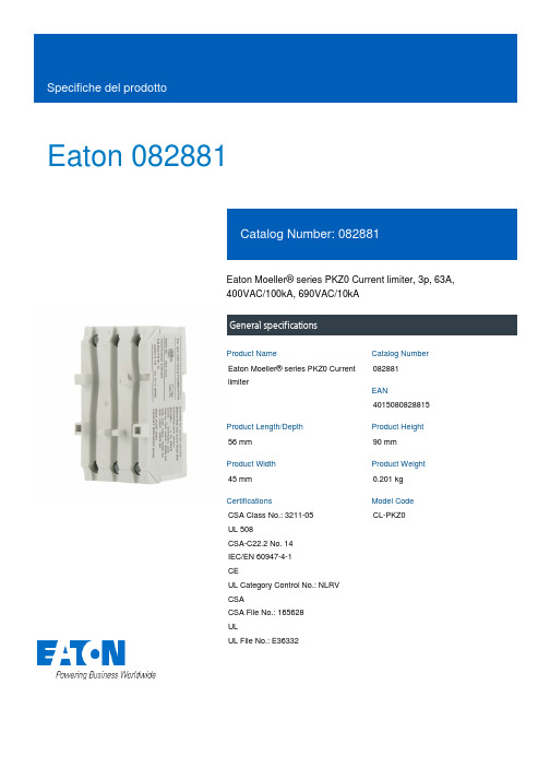
Eaton 082881Eaton Moeller® series PKZ0 Current limiter, 3p, 63A,400VAC/100kA, 690VAC/10kAGeneral specificationsEaton Moeller® series PKZ0 Currentlimiter082881401508082881556 mm90 mm45 mm0.201 kgCSA Class No.: 3211-05UL 508CSA-C22.2 No. 14IEC/EN 60947-4-1CEUL Category Control No.: NLRV CSACSA File No.: 165628ULUL File No.: E36332CL-PKZ0Product Name Catalog NumberEANProduct Length/Depth Product Height Product Width Product Weight Certifications Model Code63 AAccessoriesIs the panel builder's responsibility. The specifications for the switchgear must be observed.Max. 690 V690 V AC8.4 W0 WMeets the product standard's requirements.Is the panel builder's responsibility. The specifications for the switchgear must be observed.DIN railDoes not apply, since the entire switchgear needs to be evaluated.Meets the product standard's requirements.Meets the product standard's requirements.Meets the product standard's requirements.Is the panel builder's responsibility.0 VA DA-DC-00004945.pdfDA-DC-00004935.pdfDA-DC-00004892.pdfDA-DC-00004882.pdfDA-DC-00004884.pdfDA-DC-00004883.pdfDA-DC-00004914.pdfDA-DC-00004944.pdfDA-DC-00004962.pdfDA-DC-00004890.pdfDA-DC-00004886.pdfDA-DC-00004891.pdfDA-DC-00004920.pdfDA-DC-00004951.pdfDA-DC-00004915.pdfDA-DC-00004921.pdfeaton-manual-motor-starters-current-pkz0-current-limiter-dimensions.eps eaton-manual-motor-starters-pkz0-current-limiter-3d-drawing.epsDA-CE-ETN.CL-PKZ0DA-CD-cl_pkz0DA-CS-cl_pkz0DA-DC-00004554.pdfDA-DC-00004545.pdfeaton-manual-motor-starters-current-pkz0-current-limiter-wiring-diagram.epsRated operational current for specified heat dissipation (In) Product category10.11 Short-circuit ratingRated operational voltageEquipment heat dissipation, current-dependent PvidHeat dissipation capacity Pdiss10.4 Clearances and creepage distances10.12 Electromagnetic compatibilityMounting Method10.2.5 Lifting10.2.3.1 Verification of thermal stability of enclosures10.2.3.2 Verification of resistance of insulating materials to normal heat10.2.3.3 Resist. of insul. mat. to abnormal heat/fire by internal elect. effects10.8 Connections for external conductorsApparent powerRated conditional short-circuit current (Iq)Declarations of conformityDisegnieCAD modelmCAD modelReport di certificazione Schemi di cablaggio0 kA10.9.2 Power-frequency electric strengthIs the panel builder's responsibility.Overvoltage categoryIIIAmbient operating temperature - max55 °CPollution degree310.7 Internal electrical circuits and connectionsIs the panel builder's responsibility.Rated impulse withstand voltage (Uimp)6000 V AC10.10 Temperature riseThe panel builder is responsible for the temperature rise calculation. Eaton will provide heat dissipation data for the devices.Static heat dissipation, non-current-dependent Pvs0 WFunctionsShort-circuit current limiterCan be used for individual and group protection10.9.3 Impulse withstand voltageIs the panel builder's responsibility.Ambient operating temperature - min-25 °CTypeMotor-protective circuit-breaker, non-auto-protected in order to increase switching capacity10.2.2 Corrosion resistanceMeets the product standard's requirements.10.6 Incorporation of switching devices and componentsDoes not apply, since the entire switchgear needs to be evaluated.10.2.4 Resistance to ultra-violet (UV) radiationMeets the product standard's requirements.10.2.7 InscriptionsMeets the product standard's requirements.Eaton Corporation plc Eaton House30 Pembroke Road Dublin 4, Ireland © 2023 Eaton. Tutti i diritti riservati. Eaton is a registered trademark.All other trademarks areproperty of their respectiveowners./socialmediaDoes not apply, since the entire switchgear needs to be evaluated.63 ANext to or behind the motor protective circuit breaker The device meets the requirements, provided the information in the instruction leaflet (IL) is observed.Does not apply, since the entire switchgear needs to be evaluated.Is the panel builder's responsibility.Does not apply, since the entire switchgear needs to be evaluated.2.8 W10.5 Protection against electric shockRated uninterrupted current (Iu)Mounting position10.13 Mechanical function10.2.6 Mechanical impact10.9.4 Testing of enclosures made of insulating material 10.3 Degree of protection of assembliesHeat dissipation per pole, current-dependent Pvid。
“能效之星”产品目录(2019)

BD/BC-203N/A
BD/BC-309MD
BC/BD-147GEX
BC/BD-206GEX
≤45
5.1 电饭锅:电饭锅(1000<P≤2000)
能效指标(实测值) 能效指数η 31.705 34.0 35.1 37.1 41.9 44.3 38.43 39.155
产品型号
技术规范(要求值)
热效率值 (%)
4.71
2
珠海格力电器股份有限公司 KFR-50LW/(50583)FNhAa-A1(WIFI)
4.63
3
广东美的制冷设备有限公司
KFR-51LW/BP3DN8Y-YB301(B1)
4.57
4
广东美的制冷设备有限公司
KFR-51LW/BP3DN8Y-YB300(B1)
≥4.30
4.56
5
海信家电集团股份有限公司
附件
“能效之星”产品目录(2019)
一、终端消费类产品
1.1 电动洗衣机:波轮式全自动洗衣机
序号
制造商
海信(山东)冰箱有 1
限公司
产品型号 XQB100-V3705YD
技术规范(要求值)
能效指标(实测值)
单位功效耗电量 单位功效用水量 洗净比 单位功效耗电量 单位功效用水量 洗净比 (Ee/[(kWh)/(cyclekg)] (We/[L/(cyclekg)] (Ce) (Ee/[(kWh)/(cyclekg)] (We/[L/(cyclekg)] (Ce)
3 西安巴洛特热能科技有限公司
LL1GBQ24
2.3 热水器:燃气采暖热水炉(两用型)热水
η1:107.1;η2:104.6
序号
制造商
LTM4601A中文资料

14601afbwith PLL, Output Trackingand MarginingnTelecom and Networking Equipment n ServersnComplete Switch Mode Power Supply n Wide Input Voltage Range: 4.5V to 20V n 12A DC Typical, 14A Peak Output Current n 0.6V to 5V Output Voltagen Output Voltage T racking and MarginingnRedundant Mounting Pads for Enhanced Solder-Joint Strengthn Parallel Multiple μModules for Current Sharing n Differential Remote Sensing for Precision Regulation (L TM4601A Only)n PLL Frequency Synchronization n ±1.5% Total DC Errorn Current Foldback Protection (Disabled at Start-Up)n Pb-Free (e4) RoHS Compliant Package with Gold Finish Pads n UltraFast™ T ransient Response n Current Mode Control n Up to 95% Effi ciency at 5V IN , 3.3V OUT n Programmable Soft-Start n Output Overvoltage Protection n E nhanced (15mm × 15mm × 2.8mm) Surface Mount LGA Package1.5V/12A Power Supply with 4.5V to 20V InputEffi ciency and Power Lossvs Load CurrentThe L TM ®4601A is a complete 12A step-down switch mode DC/DC power supply with onboard switching controller , MOSFE Ts, inductor and all support components. The μModule™ is housed in a small surface mount 15mm × 15mm × 2.8mm LGA package. The L TM4601A LGA package is designed with redundant mounting pads to enhance solder-joint strength for extended temperature cycling endurance. Operating over an input voltage range of 4.5 to 20V, the L TM4601A supports an output voltage range of 0.6V to 5V as well as output voltage tracking and margining. The high effi ciency design delivers 12A continuous current (14A peak). Only bulk input and output capacitors are needed to complete the design. The low profi le (2.8mm) and light weight (1.7g) package easily mounts on the back side of PC boards. The μModule can be synchronized with an external clock for reducing undesirable frequency harmonics and allows PolyPhase ® operation for high load currents.An onboard differential remote sense amplifi er can be used to accurately regulate an output voltage independent of load current. The onboard remote sense amplifi er is not available in the L TM4601A-1.T YPICAL APPLICATIONF EATURESA PPLICATIONS DESCRIPTIONL , L T , L TC, L TM and PolyPhase are registered trademarks of Linear Technology Corporation. μModule and UltraFast are trademarks of Linear Technology Corporation. All other trademarks are the property of their respective owners. Protected by U.S. Patents including 5481178, 5847554, 6304066, 6476589, 6580258, 6677210, 6774611.OUTOUT CV LOAD CURRENT (A)50E F F I C I E N C Y (%)POWER LOSS (W)55657075954601A TA01b6024681012148085900.51.02.04.01.52.53.03.524601afbINTV CC , DRV CC , V OUT_LCL , V OUT (V OUT ≤ 3.3V withDIFFV OUT ).....................................................–0.3V to 6V PLLIN, TRACK/SS, MPGM, MARG0, MARG1,PGOOD, f SET ..............................–0.3V to INTV CC + 0.3V RUN .............................................................–0.3V to 5V V FB , COMP ................................................–0.3V to 2.7V V IN .............................................................–0.3V to 20V V OSNS +, V OSNS – ..........................–0.3V to INTV CC + 0.3V Operating Temperature Range (Note 2)....–40°C to 85°C Junction Temperature ...........................................125°C Storage Temperature Range ...................–55°C to 125°C(Note 1)Thel denotes the specifi cations which apply over the –40°C to 85°C temperature range, otherwise specifi cations are at T A = 25°C, V IN = 12V . Per typical application (front page) confi guration.SYMBOL PARAMETER CONDITIONSMIN TYP MAX UNITSV IN(DC)Input DC Voltagel4.520V V OUT(DC)Output Voltage, Total Variation withLine and LoadC IN = 10μF ×3, C OUT = 200μF, R SET = 40.2k V IN = 5V to 20V, I OUT = 0A to 12A (Note 5)l 1.4781.5 1.522V Input Specifi cations V IN(UVLO)Undervoltage Lockout Threshold I OUT = 0A3.24V I INRUSH(VIN)Input Inrush Current at StartupI OUT = 0A. V OUT = 1.5V V IN = 5V V IN = 12V0.60.7A ALEAD FREE FINISH TRAYPART MARKING*PACKAGE DESCRIPTIONTEMPERATURE RANGE L TM4601AEV#PBF L TM4601AEV#PBF L TM4601AV 133-Lead (15mm × 15mm × 2.8mm) LGA –40°C to 85°C L TM4601AIV#PBF L TM4601AIV#PBF L TM4601AV 133-Lead (15mm × 15mm × 2.8mm) LGA –40°C to 85°C L TM4601AEV-1#PBF L TM4601AEV-1#PBF L TM4601AV-1133-Lead (15mm × 15mm × 2.8mm) LGA –40°C to 85°C L TM4601AIV-1#PBFL TM4601AIV-1#PBFL TM4601AV-1133-Lead (15mm × 15mm × 2.8mm) LGA–40°C to 85°CConsult L TC Marketing for parts specifi ed with wider operating temperature ranges. *The temperature grade is identifi ed by a label on the shipping container .For more information on lead free part marking, go to: http://www.linear .com/leadfree/This product is only offered in trays. For more information go to: http://www.linear .com/packaging/P IN CONFIGURATIONA BSOLUTE MAXIMUM RATINGS ORDER INFORMATIONELECTRICAL CHARACTERISTICS(See Table 5. Pin Assignment)34601afbSYMBOL PARAMETERCONDITIONSMIN TYP MAX UNITS I Q(VIN,NOLOAD)Input Supply Bias CurrentV IN = 12V, No SwitchingV IN = 12V, V OUT = 1.5V, Switching Continuous V IN = 5V, No SwitchingV IN = 5V, V OUT = 1.5V, Switching Continuous Shutdown, RUN = 0, V IN = 12V 3.8382.54222mA mA mA mA μA I S(VIN)Input Supply CurrentV IN = 12V, V OUT = 1.5V, I OUT = 12A V IN = 12V, V OUT = 3.3V, I OUT = 12A V IN = 5V, V OUT = 1.5V, I OUT = 12A 1.813.634.29A A AINTV CC V IN = 12V, RUN > 2VNo Load4.755.3V Output Specifi cationsI OUTDC Output Continuous Current Range V IN = 12V, V OUT = 1.5V (Note 5)12A ΔV OUT(LINE) V OUT Line Regulation Accuracy V OUT = 1.5V, I OUT = 0A, V IN from 4.5V to 20V l0.3%ΔV OUT(LOAD) V OUT Load Regulation AccuracyV OUT = 1.5V, 0A to 12A (Note 5)V IN = 12V, with Remote Sense Amplifi er V IN = 12V (L TM4601A-1)ll 0.251%%V OUT(AC)Output Ripple VoltageI OUT = 0A, C OUT = 2×, 100μF X5R Ceramic V IN = 12V, V OUT = 1.5V V IN = 5V, V OUT = 1.5V 2018mV P-P mV P-P f SOutput Ripple Voltage Frequency I OUT = 5A, V IN = 12V , V OUT = 1.5V 850kHz ΔV OUT(START)Turn-On Overshoot, TRACK/SS = 10nFC OUT = 200μF , V OUT = 1.5V, I OUT = 0A V IN = 12V V IN = 5V2020mV mVt STARTTurn-On Time, TRACK/SS = OpenC OUT = 200μF , V OUT = 1.5V, I OUT = 1A Resisitive LoadV IN = 12V V IN = 5V0.50.5ms msΔV OUTLSPeak Deviation for Dynamic LoadLoad: 0% to 50% to 0% of Full Load, C OUT = 2 × 22μF Ceramic, 470μF 4V Sanyo POSCAP V IN = 12V V IN = 5V3535mV mV t SETTLE Settling Time for Dynamic Load Step Load: 0% to 50%, or 50% to 0% of Full LoadV IN = 12V 25μs I OUTPKOutput Current LimitC OUT = 200μF , Table 2 V IN = 12V, V OUT = 1.5V V IN = 5V, V OUT = 1.5V1717A A Remote Sense Amp (Note 3) (L TM4601A Only, Not Supported in the L TM4601A-1)V OSNS +, V OSNS – CM Range Common Mode Input Voltage Range V IN = 12V, RUN > 2V 0INTV CC – 1V DIFFV OUT Range Output Voltage Range V IN = 12V, DIFF OUT Load = 100kINTV CC V V OS Input Offset Voltage Magnitude 1.25mV A V Differential Gain 1V/V GBPGain-Bandwidth Product3MHzThe l denotes the specifi cations which apply over the –40°C to 85°Ctemperature range, otherwise specifi cations are at T A = 25°C, V IN = 12V. Per typical application (front page) configuration. E LECTRICAL CHARACTERISTICS44601afbSYMBOL PARAMETER CONDITIONS MIN TYP MAX UNITS SR Slew Rate 2V/μs R IN Input ResistanceV OSNS + to GND20kΩCMRR Common Mode Rejection Mode 100dBControl Stage V FB Error Amplifi er Input VoltageAccuracyI OUT = 0A, V OUT = 1.5Vl0.5940.60.606V V RUN RUN Pin On/Off Threshold 1 1.5 1.9V I SS/TRACK Soft-Start Charging Current V SS/TRACK = 0V –1–1.5–2μA t ON(MIN)Minimum On-Time (Note 4)50100ns t OFF(MIN)Minimum Off-Time (Note 4)250400ns R PLLIN PLLIN Input Resistance 50kΩI DRVCC Current into DRV CC PinV OUT = 1.5V, I OUT = 1A, DRV CC = 5V1825mA R FBHI Resistor Between V OUT_LCL and V FB 60.09860.460.702kΩV MPGMMargin Reference Voltage 1.18V V MARG0, V MARG1MARG0, MARG1 Voltage Thresholds 1.4VPGOOD Output ΔV FBH PGOOD Upper Threshold V FB Rising 71013%ΔV FBL PGOOD Lower Threshold V FB Falling –7–10–13%ΔV FB(HYS)PGOOD Hysteresis V FB Returning 1.5%V PGLPGOOD Low VoltageI PGOOD = 5mA0.150.4VThe l denotes the specifi cations which apply over the –40°C to 85°C temperature range, otherwise specifi cations are at T A = 25°C, V IN = 12V. Per typical application (front page) configuration.Note 1: Stresses beyond those listed under Absolute Maximum Ratings may cause permanent damage to the device. Exposure to any Absolute Maximum Rating condition for extended periods may affect device reliability and lifetime.Note 2: The L TM4601AE/L TM4601AE-1 are guaranteed to meet performance specifi cations from 0°C to 85°C. Specifi cations over the –40°C to 85°C operating temperature range are assured by design,characterization and correlation with statistical process controls. The L TM4601AI/L TM4601AI-1 are guaranteed and tested over the –40°C to 85°C temperature range.Note 3: Remote sense amplifi er recommended for ≤3.3V output.Note 4: 100% tested at wafer level only.Note 5: See Output Current Derating curves for different V IN , V OUT and T A .E LECTRICAL CHARACTERISTICS54601afbEffi ciency vs Load Current with 5V INEffi ciency vs Load Current with 12V INEffi ciency vs Load Current with 20V IN1.2V T ransient Response1.5V T ransient Response2.5V T ransient Response3.3V T ransient Response(See Figure 18 for all curves)1.8V T ransient ResponseTYPICAL PERFORMANCE CHARACTERISTICSLOAD CURRENT (A)E F F I C I E N C Y (%)758085154601A G0170656055505109095100LOAD CURRENT (A)50E F F I C I E N C Y (%)55657075100855104601A G026090958015LOAD CURRENT (A)100909585807570656055504601A G0351015E F F I C I E N C Y(%)V OUT 50mV/DIV 20μs/DIV4601A G04IOUT 5A/DIV1.2V AT 6A/μs LOAD STEPC OUT = 3 • 22μF 6.3V CERAMICS 470μF 4V SANYO POSCAP C3 = 100pFV OUT 50mV/DIV20μs/DIV4601A G05I OUT 5A/DIV 1.5V AT 6A/μs LOAD STEPC OUT = 3 • 22μF 6.3V CERAMICS 470μF 4V SANYO POSCAP C3 = 100pFV OUT 50mV/DIV20μs/DIV4601A G06IOUT 5A/DIV1.8V AT 6A/μs LOAD STEPC OUT = 3 • 22μF 6.3V CERAMICS 470μF 4V SANYO POSCAP C3 = 100pFV OUT 50mV/DIV20μs/DIV4601A G07I OUT 5A/DIV 2.5V AT 6A/μs LOAD STEPC OUT = 3 • 22μF 6.3V CERAMICS 470μF 4V SANYO POSCAP C3 = 100pFV OUT 50mV/DIV20μs/DIV4601A G08I OUT 5A/DIV3.3V AT 6A/μs LOAD STEPC OUT = 3 • 22μF 6.3V CERAMICS 470μF 4V SANYO POSCAP C3 = 100pF64601afb(See Figure 18 for all curves)Start-Up, I OUT = 12A (Resistive Load)Start-Up, I OUT = 0AV IN to V OUT Step-Down RatioShort-Circuit Protection, I OUT = 0AShort-Circuit Protection, I OUT = 12AT rack, I OUT = 12AT YPICAL PERFORMANCE CHARACTERISTICS V OUT0.5V/DIV5ms/DIV4601A G09I IN 0.5A/DIVV IN = 12V V OUT = 1.5V C OUT = 470μF 3s 22μFSOFT-START = 10nFV OUT 0.5V/DIV 2ms/DIV4601A G10I IN 1A/DIVV IN = 12V V OUT = 1.5V C OUT = 470μF 3s 22μFSOFT-START = 10nFINPUT VOL TAGE (V)O U T P U T V O L T A G E (V )3.04.05.55.0164601A G112.01.02.53.54.51.50.5042861214181020 3.3V OUTPUT WITH 130k ADDED FROM V OUT TO f SET 5V OUTPUT WITH 100k RESISTOR ADDED FROM f SET TO GND5V OUTPUT WITH NO RESISTOR ADDED FROM f SET TO GND 2.5V OUTPUT 1.8V OUTPUT 1.5V OUTPUT1.2V OUTPUTV FB 0.5V/DIV TRACK/SS 0.5V/DIV2ms/DIV4601A G12V OUT 1V/DIVV IN = 12V V OUT = 1.5V C OUT = 470μF 3s 22μFSOFT-START = 10nFV OUT 0.5V/DIV 50μs/DIV 4601A G13I IN 1A/DIVV IN = 12VV OUT = 1.5V C OUT = 470μF 3s 22μFSOFT-START = 10nFV OUT 0.5V/DIV 50μs/DIV 4601A G14I IN 1A/DIVV IN = 12VV OUT = 1.5V C OUT = 470μF 3s 22μFSOFT-START = 10nF74601afb(See Package Description for Pin Assignment)V IN (Bank 1): Power Input Pins. Apply input voltage be-tween these pins and PGND pins. Recommend placing input decoupling capacitance directly between V IN pins and PGND pins.V OUT (Bank 3): Power Output Pins. Apply output load between these pins and PGND pins. Recommend placing output decoupling capacitance directly between these pins and PGND pins. Review the fi gure below.PGND (Bank 2): Power ground pins for both input and output returns.V OSNS – (Pin M12): (–) Input to the Remote Sense Amplifier . This pin connects to the ground remote sense point. The remote sense amplifi er is used for V OUT ≤3.3V .NC1 (Pin M12): No Connect On the L TM4601A-1. V OSNS + (Pin J12): (+) Input to the Remote Sense Amplifi er . This pin connects to the output remote sense point. The remote sense amplifi er is used for V OUT ≤3.3V .NC2 (Pin J12): No Connect On the L TM4601A-1.DIFFV OUT (Pin K12): Output of the Remote Sense Ampli-fi er . This pin connects to the V OUT_LCL pin.NC3 (Pin K12): No Connect On the L TM4601A-1.DRV CC (Pin E12): This pin normally connects to INTV CC for powering the internal MOSFET drivers. This pin can be biased up to 6V from an external supply with about 50mA capability, or an external circuit shown in Figure 16. This improves effi ciency at the higher input voltages by reducing power dissipation in the module.INTV CC (Pin A7, D9): This pin is for additional decoupling of the 5V internal regulator . These pins are internally connected. Pin A7 is a test pin.PLLIN (Pin A8): External Clock Synchronization Input to the Phase Detector . This pin is internally terminated to SGND with a 50k resistor . Apply a clock above 2V and below INTV CC . See Applications Information.TRACK/SS (Pin A9): Output Voltage T racking and Soft- Start Pin. When the module is confi gured as a master output, then a soft-start capacitor is placed on this pin to ground to control the master ramp rate. A soft-start capacitor can be used for soft-start turn on as a stand alone regulator . Slave operation is performed by putting a resistor divider from the master output to the ground, and connecting the center point of the divider to this pin. See Applications Information.MPGM (Pins A12, B11): Programmable Margining Input. A resistor from this pin to ground sets a current that is equal to 1.18V/R. This current multiplied by 10kΩ will equal a value in millivolts that is a percentage of the 0.6V reference voltage. See Applications Information. To parallel L TM4601As, each requires an individual MPGM resistor . Do not tie MPGM pins together . Both pins are internally connected. Pin A12 is a test pin.f SET (Pins B12, C11): Frequency Set Internally to 850kHz. An external resistor can be placed from this pin to ground to increase frequency. This pin can be decoupled with a 1000pF capacitor . See Applications Information for fre-quency adjustment. Both pins are internally connected. Pin B12 is a test pin.V FB (Pin F12): The Negative Input of the Error Amplifier . Internally, this pin is connected to V OUT_LCL pin with a 60.4k precision resistor . Different output voltages can be programmed with an additional resistor between V FB and SGND pins. See Applications Information.MARG0 (Pin C12): This pin is the LSB logic input for the margining function. Together with the MARG1 pin will determine if margin high, margin low or no margin state is applied. The pin has an internal pull-down resistor of 50k. See Applications Information.PIN FUNCTIONSV IN BANK 11234567*L TM4601A-1 ONL Y89101112PGND BANK 2V OUT BANK 3V OSNS +/NC2*V OSNS –/NC1*DIFFV OUT /NC3*V OUT_LCL SGND f SET MARG0MARG1DRV CC V FB PGOOD I N T V C CP L L I N T R A C K /S S R U N C O M P M P G M TOP VIEW84601afbFigure 1. Simplifi ed L TM4601A/L TM4601A-1 Block DiagramMARG1 (Pin D12): This pin is the MSB logic input for the margining function. Together with the MARG0 pin will determine if margin high, margin low or no margin state is applied. The pin has an internal pull-down resistor of 50k. See Applications Information.SGND (Pins H12, H11, G11): Signal Ground. These pins connect to PGND at output capacitor point. See Figure 15. COMP (Pin A11): Current Control Threshold and Error Amplifi er Compensation Point. The current comparator threshold increases with this control voltage. The voltage ranges from 0V to 2.4V with 0.7V corresponding to zero sense voltage (zero current).PGOOD (Pins G12, F11): Output Voltage Power Good Indicator . Open-drain logic output that is pulled to ground when the output voltage is not within ±10% of the regula-tion point, after a 25μs power bad mask timer expires.RUN (Pin A10): Run Control Pin. A voltage above 1.9V will turn on the module, and when below 1V, will turn off the module. A programmable UVLO function can be ac-complished with a resistor from V IN to this pin that has a 5.1V zener to ground. Maximum pin voltage is 5V . Limit current into the RUN pin to less than 1mA.V OUT_LCL (Pin L12): V OUT connects directly to this pin to bypass the remote sense amplifi er, or DIFFV OUT con-nects to this pin when remote sense amplifi er is used. V OUT_LCL can be connected to V OUT on the L TM4601A-1, V OUT is internally connected to V OUT_LCL with 50Ω in the L TM4601A-1.MTP1, MTP2, MPT3 (Pins C10, D10, D11 ): E xtra Mounting Pads used for increased solder integrity strength. These pads must remain fl oating (electrical open circuit).(See Package Description for Pin Assignment)P IN FUNCTIONS SIMPLIFIED BLOCK DIAGRAMNOT INCLUDED IN THE L TM4601A-1V OSNS – = NC1V OSNS + = NC2DIFFV OUT = NC34601A F01SYMBOL PARAMETER CONDITIONS MIN TYP MAX UNITS C IN External Input Capacitor Requirement(V IN = 4.5V to 20V, V OUT = 1.5V)I OUT = 12A, 3× 10μF Ceramics2030μFC OUT External Output Capacitor Requirement(V IN = 4.5V to 20V, V OUT = 1.5V)I OUT = 12A100200μFT A = 25°C, V IN = 12V. Use Figure 1 confi guration.Power Module DescriptionThe L TM4601A is a standalone nonisolated switching mode DC/DC power supply. It can deliver up to 12A of DC output current with few external input and output capacitors. This module provides precisely regulated output voltage programmable via one external resistor from 0.6V DC to 5.0V DC over a 4.5V to 20V wide input voltage. The typical application schematic is shown in Figure 18.The L TM4601A has an integrated constant on-time current mode regulator, ultralow R DS(ON) FETs with fast switch-ing speed and integrated Schottky diodes. The typical switching frequency is 850kHz at full load. With current mode control and internal feedback loop compensation, the L TM4601A module has suffi cient stability margins and good transient performance under a wide range of operat-ing conditions and with a wide range of output capacitors, even all ceramic output capacitors.Current mode control provides cycle-by-cycle fast current limit. Besides, foldback current limiting is provided in an overcurrent condition while V FB drops. Internal overvoltage and undervoltage comparators pull the open-drain PGOOD output low if the output feedback voltage exits a ±10% window around the regulation point. Furthermore, in an overvoltage condition, internal top FET Q1 is turned off and bottom FET Q2 is turned on and held on until the overvoltage condition clears.Pulling the RUN pin below 1V forces the controller into its shutdown state, turning off both Q1 and Q2. At low load current, the module works in continuous current mode by default to achieve minimum output voltage ripple. When DRV CC pin is connected to INTV CC an integrated 5V linear regulator powers the internal gate drivers. If a 5V external bias supply is applied on the DRV CC pin, then an effi ciency improvement will occur due to the reduced power loss in the internal linear regulator. This is especially true at the higher input voltage range.The L TM4601A has a very accurate differential remote sense amplifier with very low offset. This provides for very accurate remote sense voltage measurement. The MPGM pin, MARG0 pin and MARG1 pin are used to sup-port voltage margining, where the percentage of margin is programmed by the MPGM pin, and the MARG0 and MARG1 select margining.The PLLIN pin provides frequency synchronization of the device to an external clock. The TRACK/SS pin is used for power supply tracking and soft-start programming.DECOUPLING REQUIREMENTSOPERATION94601afbThe typical L TM4601A application circuit is shown in Figure 18. E xternal component selection is primarily determined by the maximum load current and output voltage. Refer to Table 2 for specifi c external capacitor requirements for a particular application.V IN to V OUT Step-Down RatiosThere are restrictions in the maximum V IN and V OUT step down ratio that can be achieved for a given input voltage. These constraints are shown in the Typical Performance Characteristics curves labeled “V IN to V OUT Step-Down Ratio”. Note that additional thermal derating may apply. See the Thermal Considerations and Output Current Derating section of this data sheet.Output Voltage Programming and MarginingThe PWM controller has an internal 0.6V reference voltage. As shown in the Block Diagram, a 1M and a 60.4k 0.5% internal feedback resistor connects V OUT and V FB pins together. The V OUT_LCL pin is connected between the 1M and the 60.4k resistor. The 1M resistor is used to protect against an output overvoltage condition if the V OUT_LCL pin is not connected to the output, or if the remote sense amplifi er output is not connected to V OUT_LCL. The output voltage will default to 0.6V. Adding a resistor R SET from the V FB pin to SGND pin programs the output voltage:V OUT=0.6V 60.4k+R SETR SETTable 1. R SET Standard 1% Resistor Values vs V OUTR SET(kΩ)Open60.440.230.125.519.113.38.25V OUT (V)0.6 1.2 1.5 1.82 2.5 3.35The MPGM pin programs a current that when multipliedby an internal 10k resistor sets up the 0.6V reference ±offset for margining. A 1.18V reference divided by theRPGM resistor on the MPGM pin programs the current.Calculate V OUT(MARGIN):V OUT(MARGIN)=%V OUT100•V OUTwhere %V OUT is the percentage of V OUT you want to margin,and V OUT(MARGIN) is the margin quantity in volts:R PGM=V OUT0.6V•1.18VV OUT(MARGIN)•10kwhere R PGM is the resistor value to place on the MPGMpin to ground.The output margining will be ± margining of the value.This is controlled by the MARG0 and MARG1 pins. Seethe truth table below:MARG1MARG0MODELOW LOW NO MARGINLOW HIGH MARGINUPHIGH LOW MARGIN DOWNHIGH HIGH NO MARGINInput CapacitorsL TM4601A module should be connected to a low ACimpedance DC source. Input capacitors are required tobe placed adjacent to the module. In Figure 18, the 10μFceramic input capacitors are selected for their ability tohandle the large RMS current into the converter. An inputbulk capacitor of 100μF is optional. This 100μF capacitor isonly needed if the input source impedance is compromisedby long inductive leads or traces.APPLICATIONS INFORMATION104601afbLTM4601A/LTM4601A-1For a buck converter, the switching duty-cycle can be estimated as:D =V OUT V INWithout considering the inductor current ripple, the RMS current of the input capacitor can be estimated as:I CIN(RMS)=I OUT(MAX) %In the above equation, η% is the estimated effi ciency of the power module. C IN can be a switcher-rated electrolytic aluminum capacitor, OS-CON capacitor or high volume ceramic capacitor. Note the capacitor ripple current rat-ings are often based on temperature and hours of life. This makes it advisable to properly derate the input capacitor, or choose a capacitor rated at a higher temperature than required. Always contact the capacitor manufacturer for derating requirements.In Figure 18, the 10μF ceramic capacitors are together used as a high frequency input decoupling capacitor. In a typical 12A output application, three very low ESR, X5R or X7R, 10μF ceramic capacitors are recommended. These decoupling capacitors should be placed directly adjacent to the module input pins in the PCB layout to minimize the trace inductance and high frequency AC noise. Each 10μF ceramic is typically good for 2A to 3A of RMS ripple current. Refer to your ceramics capacitor catalog for the RMS current ratings.Multiphase operation with multiple L TM4601A devices in parallel will lower the effective input RMS ripple current due to the interleaving operation of the regulators. Application Note 77 provides a detailed explanation. Refer to Figure 2 for the input capacitor ripple current requirement as a function of the number of phases. The fi gure provides a ratio of RMS ripple current to DC load current as function of duty cycle and the number of paralleled phases. Pickthe corresponding duty cycle and the number of phases to arrive at the correct ripple current value. For example, the 2-phase parallel L TM4601A design provides 24A at 2.5V output from a 12V input. The duty cycle is DC = 2.5V/12V = 0.21. The 2-phase curve has a ratio of ~0.25 for a duty cycle of 0.21. This 0.25 ratio of RMS ripple current to a DC load current of 24A equals ~6A of input RMS ripple current for the external input capacitors. Output CapacitorsThe L TM4601A is designed for low output voltage ripple. The bulk output capacitors defi ned as C OUT are chosen with low enough effective series resistance (ESR) to meet the output voltage ripple and transient requirements. C OUT can be a low ESR tantalum capacitor , a low ESR polymer capacitor or a ceramic capacitor . The typical capacitance is 200μF if all ceramic output capacitors are used. Additional output fi ltering may be required by the system designer, if further reduction of output ripple or dynamic transient spike is required. Table 2 shows a matrix of different output voltages and output capacitors to minimize the voltage droop and overshoot during a 5A/μs transient. The table optimizes total equivalent ESR and total bulk capacitance to maximize transient performance.Figure 2. Normalized Input RMS Ripple Current vs Duty Factor for One to Six Modules (Phases)A PPLICATIONS INFORMATION DUTY FACTOR (V OUT /V IN )0.60.50.40.30.20.104601A F02R M S I N P U T R I P P L E C U R R E N T D C L O A D C U R R E N TLTM4601A/LTM4601A-1Multiphase operation with multiple L TM4601A devices in parallel will lower the effective output ripple current due to the interleaving operation of the regulators. For example, each L TM4601A’s inductor current of a 12V to 2.5V multiphase design can be read from the Inductor Ripple Current vs Duty Cycle graph (Figure 3). The large ripple current at low duty cycle and high output voltagecan be reduced by adding an external resistor from f SET to ground which increases the frequency. If the duty cycle is DC = 2.5V/12V = 0.21, the inductor ripple current for 2.5V output at 21% duty cycle is ~6A in Figure 3.Figure 4 provides a ratio of peak-to-peak output ripple cur-rent to the inductor current as a function of duty cycle and the number of paralleled phases. Pick the corresponding duty cycle and the number of phases to arrive at the correct output ripple current ratio value. If a 2-phase operation is chosen at a duty cycle of 21%, then 0.6 is the ratio. This 0.6 ratio of output ripple current to inductor ripple of 6A equals 3.6A of effective output ripple current. Refer to Ap-plication Note 77 for a detailed explanation of output ripple current reduction as a function of paralleled phases.The output voltage ripple has two components that are related to the amount of bulk capacitance and effective series resistance (ESR) of the output bulk capacitance. Therefore, the output voltage ripple can be calculated with the known effective output ripple current. The equation: ΔV OUT(P-P) ≈ (ΔI L /(8 • f • m • C OUT ) + ESR • ΔI L ), where fFigure 4. Normalized Output Ripple Current vs Duty Cycle, Dlr = V T/L , Dlr = Each Phase’s Inductor CurrentFigure 3. Inductor Ripple Current vs Duty CycleAPPLICATIONS INFORMATIONDUTY CYCLE (V OUT /V IN )I L (A )24681012204060804601A F032.5V OUTPUT5V OUTPUT 1.8V OUTPUT 1.5V OUTPUT 1.2V OUTPUT 3.3V OUTPUT WITH 130k ADDED FROM V OUT TO f SET 5V OUTPUT WITH 100k ADDED FROM f SETTO GNDDUTY CYCLE (V O /V IN )1.000.950.900.850.800.750.700.650.600.550.500.450.400.350.300.250.200.150.100.0504601A F04P E A K -T O -P E A K O U T P U T R I P P L E C U R R E N T D I r R A T I O =。
高电阻电热合金丝规格与米电阻一缆表及双金属材料进厂检验技术参数对照表

高电阻电热合金丝规格与米电阻一缆表
双金属材料进厂检验技术参数对照表共10 页第1 页
双金属材料进厂检验技术参数对照表共10页第2 页
双金属材料进厂检验技术参数对照表共10页第3 页
双金属材料进厂检验技术参数对照表共10 页第4 页
双金属材料进厂检验技术参数对照表共10 页第5 页
双金属材料进厂检验技术参数对照表共10 页第6 页
双金属材料进厂检验技术参数对照表共10 页第7 页
双金属材料进厂检验技术参数对照表共10 页第8 页
双金属材料进厂检验技术参数对照表共10 页第9 页
双金属材料进厂检验技术参数对照表共10 页第10 页。
ALINCO DJ-460说明书
1 ⑯ 麦克风插孔此插孔用于延伸麦克风,我们推荐使用ALINCO 公司的选择附件(EME-4或EME-2). ⑰ H/L (高/低)开关 此开关用于以高到低(或从低到高)改变发射功率,“H ”端为高(左边),“L ”端为低(右边)。
五、控制功能:液晶显示框(LCD )① TMS (定时扫描)按下“F ”键并保持按下状态,然后按“TMS ”键,LCD 上将显示TMS,TMS 开时,启动定时扫描,TMS 关时,启动忙扫描。
②③④DSQ (DTMF 静噪)按下“F ”键并保持按下状态,然后按“G P DSQ ”键,LCD 上将显示DSQ 。
(见DSQ 功能)⑤BS (省电)⑥⑦存储跳行按下“F”键并保持按下状态,然后按“M.SKIP”键,在存储扫描期间,M上方将显示出▼标记,这时的存储器号码将被跳过。
⑧V/M按下V/M键,LCD上将交替显示V和M。
M表示处于存储状态。
闪烁的M表明频率尚未存入该存储单元中。
⑨存储单元号本机具有20个存储容量(0-19),存储信道号将以C代替。
⑩S/RF(信号/射频)显示出接收时的信号强度以及发射时的RF电平。
⑪①T.SQ(单音静噪)-选择键按下“F”键并保持按下状态,然后按“T.SQ”键,LCD上将显示T.SQ。
(见单音静噪功能)②ENC(编码器)按下“F”键并保持按下状态,然后按“ENC”键,LCD上将显示ENC(见单音编码器功能)。
③“+/-”(Transmit Shift)按下“F”键并保持按下状态,然后按“+/-”键。
(1)按一下,LCD上显示“+”(正)。
(2)再按LCD上显示“-”(负)。
(3)再按,LCD上无标记显示(详见中继器频差功能)。
④“●”(小数点)当电台处于VOF或存储状态时,小数点区分MHz和100KHz。
当电台处于扫描状态时,小数点将闪烁。
⑤KL 键锁定(见PTT键锁定功能)⑥FL 频率锁定(见频率锁定功能)2⑦“●”(单声频率小数点)此小数点区分单声频率KHz和Hz。
电能质量分析仪说明书
8
用户体验
■■ 高分辨率Leabharlann 示手持式电能质量分析仪■■ 全中文操作界面
■■ USB高速传输数据
■■ 8芯大容量电池
■■ 接口隔离 ,操作安全
■■ 结构坚固 抗震防跌
9
手持式电能质量分析仪
功能概览
■■ E6000功能介绍 实时显示
表格图或趋势图显示记录项状态,同时记录暂态、稳态事件。
■■ E6100功能介绍
功能特点121彩色液晶显示1280800分辨率标配usbethernet配备pc软件数据下载分析以及报表生成提供丰富功能按键并支持触摸屏控制canscope是广州致远电子股份有限公司最新推出的一款can总线开发测试工具基于我司多年can总线分析仪器的研发经验它不仅具有成熟稳定的can层协议分析处理能力同时还集成了数字示波器的核心功能使用户在获取can文信息的同时还可以实时观测总线物理层上的模拟波形从而从物理层协议层应用层等各个层次全方面地帮助用户快速而准确地发现并定位错误极大地提升了can总线的开发与测试效率
学科带头人周立功教授
周立功 1964年3月生,湖南人,教授,国内著名的嵌入式系统技术专家,先
后出版了40余本嵌入式系统专业技术图书与教材。现任中国计算机学会中国微 机(嵌入式系统)专家委员会委员,中国软件行业协会嵌入式系统分会常务理 事,广东省计算机学会单片机与嵌入式系统分会副理事长。
合作伙伴
ECA全球合作伙伴
E6000 手持式 IEC 61000-4-30 A级 4通道电压,4通道电流 5.6寸,640x480分辨率 支持 支持 支持 支持 支持 支持 支持 支持 USB 2.0 8G 263X168X65(mm)
E6100 便携式 IEC 61000-4-30 A级 4通道电压,4通道电流 8寸,800x600分辨率 支持 支持 支持 支持 支持 支持 支持 支持 1路 支持 USB 2.0 1路 8G(可选32G) 338X222X73(mm)
宇控yk100变频器说明书最高频率
宇控yk100变频器说明书最高频率
1、基本频率
和变频器的最大输出电压对应的频率称为基本频率,用fBA表示。
在绝大多数情况下,基本频率和电动机的额定频率相同,即fBA=fc=50Hz。
设定变频器的最大输出电压必须小于或等于电动机的额定电压。
基本频率应以电动机的额定工作频率进行设置,如果电动机的额定工作频率为50Hz,则基本频率应设置为50Hz,如果电动机的额定工作频率为60Hz(或100Hz),则基本频率应设置为60Hz,(或100Hz)。
如果电动机选用专用的变频电动机,则一般都标注恒转矩、恒功率调速范围。
如果标注5~100赫兹为恒转矩,100~150赫兹为恒功率,则基本频率应设置为100Hz。
如果变频器的基本频率设定不当,有可能出现相同负载下,电动机电流值比工频运行时的电流大;在低频情况下,电流值偏大现象更为严重。
例如将380伏,50Hz的电动机用的变频器的基本频率设定为20.5Hz时就会出现上述情况。
2、最高频率
最高频率是指变频器允许输出的最高频率,用fmax表示。
最高频率设置范围很宽,通用频器高频率为50/60Hz,有的达400Hz,但在大多数情况下,最高频率设定为与基本频率相等。
因为
运行频率过高,负载转矩将增加(尤其是平方转矩负载),这将使电动机过载,所以必须把最高频率限制在基本频率以内。
QY90K汽车起重机技术规格(国Ⅲ、OM457LA.Ⅲ.9)_2010年9月版
QY90K汽车起重机亮点简介1、独有的双纵臂后桥悬挂系统,及一、二、五桥转向,二、四、五桥驱动模式。
底盘转向灵活、驱动力强劲。
2、独有的“U”形截面吊臂,自重轻、强度大,承载力更强。
3、先进的嵌入式臂头,结构件强度大,下滑块面积变大,受力状况更好,伸缩更加平稳,可有效防止吊臂在侧载后的扭转现象。
3、自身可携带一块1.2t固定配重,满足大部分工况需求。
4、专有MATLAB模拟优化控制程序、速度分级功能,动作平顺、操纵可靠、作业高效。
5、整车智能化检测故障自诊断系统。
6、卓越的结构件焊接技术,整机关键焊缝均采用焊接机械手焊接,工艺先进、质量可靠。
QY90K汽车起重机技术规格汽车式起重机型号:QY90K最大额定起重量:90t一、技术介绍1、底盘部分徐工设计、制造,豪华超宽驾驶室,5桥底盘,驱动/转向模式为10×6×6。
1.1、车架徐工设计、制造,防扭转箱型结构,进口高强度钢材制造。
支腿箱体位于1桥和2桥之间以及车架后端,具有前后牵引挂钩。
1.2、底盘发动机制造商:戴姆勒股份公司(德国奔驰);型号:OM457LA.Ⅲ/9;型式:直列、六缸、液冷、四冲程、增压中冷、柴油发动机;环保性:环境排放符合国Ⅲ标准(GB17691-2005);燃料箱容量:约400L。
1.3、动力传动系统1.3.1变速箱德国ZF原装进口变速箱,操纵可自动和手动选择,自动显示当前档位和手动操纵需要更换的档位。
具有12个前进档和2个倒档,即可满足低速场地行驶和爬坡行驶,又可满足高速公路行驶。
1.3.2车桥高强度桥,维护简便。
第一桥:单胎,转向不驱动;第二桥:单胎,转向、驱动;第三桥:双胎,不转向不驱动;第四桥:双胎,不转向、驱动;第五桥:单胎,转向、驱动。
1.3.3、传动轴端面齿联结式传动轴,传递扭矩大。
优化力传输,传动轴传动平稳、可靠。
1.4、桥悬挂前悬架,纵置板簧式,筒式减振器;后悬架,双轴平衡、纵置板簧式,板簧与推力杆导向。
- 1、下载文档前请自行甄别文档内容的完整性,平台不提供额外的编辑、内容补充、找答案等附加服务。
- 2、"仅部分预览"的文档,不可在线预览部分如存在完整性等问题,可反馈申请退款(可完整预览的文档不适用该条件!)。
- 3、如文档侵犯您的权益,请联系客服反馈,我们会尽快为您处理(人工客服工作时间:9:00-18:30)。
1、独有的双纵臂后桥悬挂系统,及一、二、三、六桥转向,三、五、六桥驱动模式。
底盘转向灵活、驱动力强劲。
2、独有的 “U”形截面吊臂,自重轻、强度大,承载力更强。
3、先进的嵌入式臂头,结构件强度大,下滑块面积变大,受力状况更好,伸缩更加平稳,可有效防止吊臂在侧载后的扭转现象。
3、独有的自装卸、多组合平衡重系统,提供多达420种主臂吊装工况。
4、卓越的结构件优化技术,以55吨产品自重提供100吨级起重性能。
5、专有MATLAB模拟优化控制程序、速度分级功能,动作平顺、操纵可靠、作业高效。
6、整车智能化检测故障自诊断系统。
7、卓越的结构件焊接技术,整机关键焊缝均采用焊接机械手焊接,工艺先进、质量可靠。
伸缩臂汽车式起重机型号QY100K-Ⅰ最大额定起重量:100t一、技术介绍1、底盘部分徐工设计、制造,豪华超宽驾驶室,6桥底盘,驱动/转向模式为12×6×6。
1.1、车架徐工设计、制造,防扭转箱型结构,进口高强度钢材制造。
支腿箱体位于2桥和3桥之间以及车架后端,具有前后牵引挂钩。
1.2、底盘发动机制造商:戴姆勒.克莱斯勒公司;型号:OM460LA;型式:电控、直列六缸、水冷却、增压中冷、电喷、柴油发动机;环保性:符合欧洲Ⅲ标准;燃料箱容量:约430L。
1.3、动力传动系统1.3.1、变速箱德国ZF自动传动箱,由液压变矩器、闭锁离合器、行星变速器组成,6个前进档和1个倒退档,稳定、可靠。
1.3.2、分动箱德国ZF,2档,采取大输入扭矩,带差速锁。
1.3.3、桥高强度桥,维护简便。
第一桥:单胎,转向但不驱动;第二桥:单胎,转向但不驱动;第三桥:单胎,驱动、转向;第四桥:双胎,不驱动也不转向;第五桥:双胎,驱动但不转向;第六桥:单胎,驱动、转向。
1.3.4、传动轴驱动轴均采用端面齿连接,优化动力传输,传递扭矩大。
维护简便,方便拆卸和安装。
1.4、桥悬挂前悬架,纵置板簧式,筒式减振器,板簧与推力杆导向;后悬架,双轴平衡、纵置板簧式,板簧与推力杆导向。
底盘的新悬挂机构,加大了车轮上下跳动量,提高了车辆的通过性。
第4、5载重桥采用平衡梁+纵置板簧柔性悬挂,保证了桥荷的平衡,避免了行车时的震动。
1.5、转向1、2、3、6桥转向,机械式转向机构,带有液压助力。
方向盘位置可调。
1.6、轮胎12.00R24,子午线轮胎,适用于重型载重汽车,通用性强。
1.7、制动行车制动:双回路气压制动,作用于前桥和后桥的刹车鼓上;驻车制动:弹簧加载,作用于3、4、5、6桥的所有刹车鼓上;辅助制动:柴油发动机排气制动。
1.8、底盘驾驶室新型豪华驾驶室,配CD音响、可调式航空座椅,可调式方向盘,四点大视野后视镜,电控洗窗器,电动门窗。
配置室内冷暖空调。
2、液压系统定量泵,通过取力器联接至发动机,控制辅助转向、下车液压支腿。
液压油箱容量:约230升。
2.1、液压支腿4点支撑,水平和垂直支腿全液压操纵,底盘两侧装有电控操纵控制台,控制台装夜光水平仪,并有照明灯和增速按钮。
水平支腿为两级伸缩方式,支腿的支脚用滑动装置收存垂直支腿下。
360度作业:不需要第五支腿的情况下主臂可以完成全圆周等重量起重作业。
1.11、电气设备24V直流,负极搭铁,2个储电池,照明按中国道路交通标准,包括前大灯,雾灯,倒车灯。
支腿操作电控。
底盘采用CAN总线系统数据传输快速、稳定、准确等。
1.12、工具随机配置一套维修工具2、起重机上车部分2.1、回转支承三排滚柱式回转支承,可360°连续全回转,回转支承滚柱轨道密封可防水防尘。
2.2、上车发动机制造商:瑞典沃尔沃;型号:TAD720VE;型式:直列六缸、水冷却、增压中冷、柴油发动机;环保性:符合欧洲II标准;燃料箱容量:约250L。
2.3、转台采用细晶粒高强度钢焊接,抗扭框架结构,承载能力强。
2.4、液压系统主卷、副卷、变幅和伸缩为开式回路,采用恒功率变量泵控制方式,通过主阀上的负载反馈口改变泵的排量,使泵的压力、流量自动调节到最佳大小,控制性能优越、微动性好。
起升具有轻载高速、重载低速的特点。
变幅采用重力下放,节能性好。
双缸绳排伸缩机构,同步+顺序伸缩。
回转为闭式系统,通过调节变量泵斜盘的角度来改变泵的流量及压力油的方向,从而改变回转马达的转速和旋转方向,微动性好、旋转平稳。
具有自由滑转功能。
液压油箱容量:约1200升。
2.4.1、液压油散热器与液压系统串联,功率大,能有效降低系统油温。
2.5、控制电比例先导式控制,CAN总线技术,结合先进的PLC控制技术,实现系统的逻辑控制,控制方式集成度高,故障诊断便捷,操作简单、舒适,灵敏度高,可无级调速。
2.6、主/副起升机构液压马达驱动,内置行星齿轮减速机和常闭式制动器,专用防乱绳卷筒,抗缠绕钢丝绳。
主、副起升机构单独运转。
主起升机构,单绳拉力103KN,钢丝绳直径φ22mm,长度230m。
副起升机构,单绳拉力74KN,钢丝绳φ22mm,长度160m。
2.7、变幅机构1根装有平衡阀的差动油缸;变幅角度:-2°~81°。
2.8、回转机构液压马达驱动,内置行星齿轮减速,内置常闭式制动器。
回转速度可无级调速。
2.9、起重臂由1节基本臂和4节伸缩臂组成,采用抗扭曲设计,高强度结构钢制造,吊臂截面为U形,起重作业稳定性好。
滑块间隙可调。
臂端滑轮标准配置为7个滑轮。
2.10、上车操纵室按人机工程学设计,安全舒适,装有安全玻璃和保护栏。
车窗装有遮阳板,外开式车门,可调式座椅。
上车操纵室可向后倾斜20°,视野开阔,配置冷暖空调。
2.11、安全装置液压系统配置液压平衡阀、液压溢流阀、液压双向锁等装置,保证系统稳定安全。
赫思曼力限器系统,采用先进的微处理器技术,其功耗小、功能强、灵敏度高、操作简便。
大屏幕的液晶显示器,以中文和图形方式显示力矩百分比、实际起重量、额定起重量、幅度、吊臂长度、角度、最大起升高度、工矿代码、倍率、限制角度、信息代码等起重作业参数。
具有完整的预先报警、超载停止作业功能。
系统还具有超载记忆功能(黑匣子)和故障自诊断功能。
卷扬设置三圈保护器,防止钢丝绳过放。
臂头设置高度限位,防止钢丝绳过卷。
2.12、平衡重具有人工遥控自装卸功能,利用两个液压油缸悬挂在转台尾部。
短距离转场时,可在车架中间携带一块8.3t基本平衡重。
具体工况组合如下:名称 工况Ⅰ 工况Ⅱ 工况Ⅲ 工况Ⅳ 组合重量(t)0 8.3 16.3 22.2具体自重、数量如下:名称 配重Ⅰ 配重Ⅱ 配重Ⅲ自重(t) 8.3 8 5.9数量 1 1 12.13、副起重臂高强度钢制造,长10.6m~18.1m,可选装1节4米加长副臂,安装角度0°、15°、30°;公路行驶时可附在主臂侧面。
2.14、吊钩名称 100T 50T 7T自重(t) 1.017 0.505 0.223数量 1 1 1滑轮组 6 3 02.15、上车集中润滑系统德国递进式集中润滑系统,电脑编程控制,各润滑点油料充足,使车辆保养更加轻松、方便。
自动润滑点为回转支承,吊臂销轴和起升机构轴承。
3、颜色起重机底盘,轮辋:深灰色;驾驶室,起重机上车和主臂:工程黄色。
二、QY100K-Ⅰ汽车起重机主要外购配套件表(以产品实物为准) 序号 部件名称 型号规格 供货厂家1 下车发动机 OM460LA 戴姆勒.克莱斯勒公司2 变速箱 12AS-2302IT 德国ZF公司3 分动箱 ZF(德国)4 桥 徐工徐州美驰车桥有限公司5 轮胎 12.00R24 上海双钱6 液压主泵 博世力士乐(德国)、德国林德7 水平油缸 QY100K.59.6 徐工徐州液压件厂、张家口长城液压油缸厂8 垂直油缸 QY100K.59.13 徐工徐州液压件厂、张家口长城液压油缸厂9 上车发动机 TAD720VE 沃尔沃(瑞典)10 回转支承 徐州罗特艾德回转支承有限公司11 回转机构 意大利戴纳密克12 回转马达 北京华德液压泵厂、贵州力源液压有限公司13 起升机构 博世力士乐(北京)液压有限公司、泰安福神14 起升马达 博世力士乐(德国)、萨澳(美国)15 伸缩油缸 QY100K.16 成都油缸厂16 变幅油缸 QY100K.28 成都油缸厂17 变幅平衡阀 德国布赫液压有限公司18 伸缩平衡阀 浙江圣邦液压有限公司19 起升平衡阀 博世力士乐(德国)20 上车多路阀 德国布赫液压有限公司、AMCA(荷兰昂马凯)21 力矩限制器 IFLEX5 德国赫思曼(PAT)22 左、右先导手柄阀 英国P+G(上海派芬代理)23 卡套管接头 德国EMB或PARKER24 液压油缸密封件 美国宝色霞板25 主臂伸缩用轴承 日本NSK、日本NTN、日本光洋、美国BUC、奥地利STE26 主臂伸缩钢丝绳 德国27 主臂板材 WELDOX960 瑞典钢铁公司阿克吉隆桑德钢厂28 钢丝绳 德国 CASAR、德国 DIEPA三、QY100K-Ⅰ汽车起重机基本性能参数1、起重机行驶状态主要技术参数表 遵从于技术改进 类别项 目 单位 参数 整机全长 mm 15600 整机全宽 mm 3000 整机全高mm 3850 第一、二轴距 mm 1420 第二、三轴距mm 2420 第三、四轴距mm 1800 第四、五轴距 mm 1420 尺 寸 参 数轴距 第五、六轴距 mm 1505 行驶状态整车自重kg 58000第一、二、三轴kg 8000、8000、8000 重量 参数 轴荷第四、五、六轴 kg 13000、13000、8000发动机额定功率 KW/(r/min) 360/1800 动力 参数发动机额定扭矩 N.m/(r/min)2200/1300最高行驶速度 km/h 80 最小转弯直径 m 24 最小离地间隙 mm 307 接近角 ° 20 离去角° 14 制动距离(车速为30km/h)m <10 最大爬坡能力%40行 驶 参 数百公里油耗L802、起重机作业状态主要技术参数表 类别 项目单位 参数 最大额定总起重量 t 100 最小额定幅度m 3 平衡重处mm 4200 转台尾部回转半经副卷处 mm 4590 基本臂kN.m 3450 最长主臂kN.m 1950 最大起重力矩 最长主臂+副臂 kN.m 1230 纵向m 7.56 支腿跨距(全伸) 横向 m 7.6 基本臂 m 13.5 最长主臂m 50.9 起升高度 最长主臂+副臂(18.1m) m 68.8基本臂 m 13.5 最长主臂m51起重臂长度最长主臂+副臂m51+18.1+4(选装4米节)主要 性 能 参 数 副臂安装角 ° 0、15、30 起重臂变幅时间 起臂s 75 起重臂伸缩时间 全伸/全缩s 160 最大回转速度m/min 2 同时伸 s 25 水平 支腿 同时缩s 15 同时伸 s 45 支腿伸缩时间垂直 支腿 同时缩s 25 主起升机构 m/min 105 工 作 速 度 参 数起升速度(单绳,第四层) 副起升机构 m/min 104 发动机额定功率 kw/(r/min) 174/2300 发动机额定扭矩 N.m/(r/min) 854/1400 发动机额定转速 r/min 2300 动 力 参 数 发动机稳定怠速 r/min 800 机外辐射 dB(A) ≤118作业 噪声司机位置处dB(A)≤903、QY100K-Ⅰ汽车起重机起重机主要起重性能表表1主臂起重性能表 单位:吨22.2t平衡重 全伸支腿 360°作业幅度主臂长度(m)(m) 13.518.19 22.8827.5632.2536.9441.63 46.31 513 100 804 88 73 625 70 63 61 42 416 57 56 53 42 37.832.57 47 50 45.840 35.130.425.68 40.541.8 41.236.432.528.424.120.19 34.536.2 35.833.330.126.522.71910 30 31.6 31 30.828 24.521.417.8 15.412 24 23.825 24.322 19.216.3 13.814 17.8 17.919.420.319.417.314.8 12.716 13.714.915.816.815.713.5 11.618 10.511.812.713.213.912.2 10.620 9.5 10.310.811.411.2 9.722 7.6 8.4 9.1 9.6 9.9 8.924 6.6 7.5 8 8.3 8.326 5.4 6.2 6.7 6.9 7.328 5.1 5.6 5.9 6.230 4.2 4.6 5 5.232 3.4 3.8 4.2 4.434 3.2 3.5 3.736 2.6 2.9 3.138 2.3 2.640 1.9 2.142 1.7倍率 12 10 8 6 5 4 4 3 2 使用吊100t吨吊钩 50吨吊钩钩 (1017kg) (505kg)不带平衡重 全伸支腿 360°作业主臂长度(m)幅度(m) 13.5 18.19 22.8827.5632.2536.9441.63 46.31513 93 804 68 73 625 55 63 61 42 416 45 56 53 42 37.8 32.57 36.5 40.9 40.6 40 35.1 30.4 25.68 28.2 27.8 27.6 29.6 31 28.4 24.1 20.19 20.5 20.2 20 21.8 23.1 24 22.7 1910 15.5 15.3 15.1 16.7 17.8 18.7 19.4 17.8 15.412 9.1 9 10.4 11.4 12.2 12.7 13.2 13.614 5.5 5.4 6.7 7.6 8.3 8.8 9.3 9.616 3 4.2 5.1 5.8 6.3 6.7 718 1.3 2.5 3.3 4 4.4 4.8 5.120 1.2 2 2.6 3.1 3.4 3.722 1 1.5 2 2.4 2.624 1.2 1.5 1.826 1.1倍率 12 10 8 6 5 4 4 3 2 100t吨吊钩 50吨吊钩使用吊钩 (1017kg) (505kg)22.2t 平衡重 全伸支腿 侧、后方作业主臂 51m 主臂仰角 10.6 18.1 副臂0°副臂15° 副臂30° 副臂0° 副臂15° 副臂30°幅度 幅度幅度幅度幅度 幅度起重量 (m) 起重量 (m)起重量 (m)起重量 (m)起重量 (m) 起重量 (m)78° 7 13.5 5 15.9 3.5 18.1 3.6 15.4 2.7 19.6 2.1 23.375° 6.5 16.5 4.3 18.9 3.4 20.9 3.3 18.8 2.5 22.9 2 26.572° 6 19.5 4 21.8 3.3 23.8 3.1 21.9 2.4 26.1 1.9 29.670° 5.2 21.4 3.8 23.7 3.2 25.6 2.9 24.3 2.3 28.3 1.8 31.665° 4.5 26.1 3.6 28.3 3.1 30.1 2.7 29.6 2.2 33.4 1.7 36.460° 4.1 30.6 3.4 32.7 3 34.3 2.5 34.6 2 38.2 1.6 40.955° 3.5 34.8 3.2 36.8 2.9 38.2 2.3 39.4 1.9 42.7 1.5 45.150° 2.5 38.8 2.3 40.6 2.2 41.8 1.8 43.8 1.6 46.9 1.4 49 45° 1.8 42.5 1.7 44.1 1.6 45.1 1.2 48 1.1 50.7 1 52.440° 1.2 45.8 1.1 47.2 1 48.1-- -- -- ---- --吊钩重量225Kg续表2 副臂起重性能表 单位:吨22.2t 平衡重 全伸支腿 侧、后方作业51m 主臂14.6副臂 22.1副臂 副臂0° 副臂15° 副臂30° 副臂0° 副臂15° 副臂30° 主臂仰角 起重量(kg) 幅度(m) 起重量(kg) 幅度(m) 起重量(kg)幅度(m) 起重量(kg)幅度(m) 起重量(kg)幅度(m)起重量(kg)幅度(m)78 7 15.3 4.8 18.6 3.4 21.6 4.5 18.6 3 23.7 2.1 28.1 75 6 18.6 4.2 21.9 3.1 24.7 3.9 22.2 2.7 27.2 1.8 31.4 72 5.5 21.8 4 25 3 27.7 3.6 25.8 2.4 30.6 1.8 34.7 70 4.2 23.9 3.8 27.1 2.9 29.7 3.4 28.1 2.4 32.9 1.8 36.8 65 3.9 29.1 3.3 32 2.7 34.4 3 33.8 2.1 38.3 1.6 41.8 60 3.2 34.0 3.1 36.8 2.5 38.9 2.7 39.2 2.1 43.4 1.5 46.6 55 2.2 38.6 2 41.2 1.9 43.1 1.8 44.3 1.6 48.2 1.4 50.9 50 1.3 42.9 1.2 45.3 1.1 46.9 1 49.0 0.9 52.6 0.8 54.94、起升高度曲线。