MTX多路温度记录仪曲线版英文操作说明
多点温度测试仪用户手册

多点温度测试仪用户手册多点温度测试仪可连续测试256组曲线的测温仪!TOPCITY---Temperature Profiling for IndustryTOPCITY ELECTRONICS CO.,LTD重要注意事项和安全信息感谢您选用TC smart系列温度曲线测试仪,该仪器是特别为波峰焊锡机、回流焊配套的在线式测温装置,具备波峰焊﹑回流焊两用功能,具有0.05S~600S之间12000种可选择的采样速率,每通道可记录数据120000点,配合计算机软体的后台分析功能即可进行温度曲线与生产工艺的考量;在线式设计,免除离线式分析仪的困扰。
被电子生产企业广泛用于贴装和插件PCB 焊接工艺的考量,同时也适用于其它行业的温度测绘(如食品、冶金、汽车、环境、涂装、烤炉、隧道炉……)。
使用此温度曲线测试仪时,必须遵守这些安全注意事项,以免发生安全事故和损坏仪器。
1、在使用或操作此设备之前,请仔细阅读和理解本手册。
2、非本仪器维护人员和未经培训合格的人员切勿随意使用本仪器。
3、第一次使用仪器时,请先除去仪器和托架保护盒上的保护膜。
4、仪器使用时必须置入托架保温盒内,并保证保温盒完好无损,以免高温损坏仪器及引发事故。
5、仪器属高温传导体,操作使用时应注意人身及设备安全。
6、本仪器应在洁净的环境中使用, 裸露金属不能接触带电物体。
7、请不要在露天、高温多湿的条件下直接使用、存储仪器。
8、请不要在强静电、电磁干扰源附近使用本仪器。
9、检修时,请关掉电源,以防损坏元器件。
10、使用或存储仪器时应保持平稳,不得有倾斜或不稳定现象,以防止仪器滑落。
11、仪器内电压不足时仪器报警指示灯被点亮成绿色,须及时充电,以确保仪器正常使用功能。
12、仪器使用后,请及时将仪器放回仪器箱内,以免意外损坏仪器。
13、该仪器可在-25℃~55℃的范围内被运输及保存。
在运输过程中,请尽量避免过高的湿度、振动压力或机械冲击。
14、本仪器属于精密设备,请勿随意拆装。
数显温度计使用说明书-extech tm500

User Manual12-Channel Thermocouple Datalogger Model TM500Additional User Manual Translations available at IntroductionCongratulations on your purchase of the Extech TM500 Thermometer, an SD Logger Series meter. This meter displays and stores temperature readings from up to twelve (12) Type K, J, T, R, E, or S thermocouple temperature probes. Logged data readings are stored on an SD card for transfer to a PC. This meter is shipped fully tested and calibrated and, with proper use, will provide years of reliable service. Please visit the Extech Instruments website () to check for the latest version of this User Guide.Meter Description1.Thermocouple inputs2.DC power adapter, SD memory slot, and PC interface jack3.Power ON‐OFF and Backlight key4.HOLD and NEXT key5.Power ON‐OFF and ESC key6.REC and ENTER7.TYPE ▲ key (K, J, T, R, E, or S)8.LOGGER (Offset) key9.SET (Time Check) key10.PAGE ▼ key (Display T1‐8 or T9‐12)26 810Display Description1.Temperature Channel number (1 – 8 or 9 – 12) 2.Thermocouple Type indicator (K, J, T, E, R, or S) 3.Temperature reading 4. Units of measure (C/F)Getting StartedPower ON ‐OFF∙ Power the meter by pressing the power button .∙ Press and hold the power button for at least 3 seconds to power OFF the meter.∙ This meter is powered by eight (8) 1.5VDC ‘AA’ batteries or by optional AC adaptor. If the meter will not switch ON please check that fresh batteries are installed in the rear battery compartment (refer to the battery replacement section later in this guide) or, in the case of the AC adaptor, check that the adaptor is connected correctly to the meter and to an AC source (refer to the AC Power Adaptor section later in this guide).Connecting Thermocouple SensorsThis meter can accept Thermocouple temperature probe Types K, J, T, E, R, or S.∙ Connect up to twelve (12) thermocouples to the sub ‐miniature jacks at the top of the meter labeled T1 through T12.∙ Select the desired mode of operation, and other setup features, in the Setup Mode. Refer to the Setup Mode section below.IMPORTANT NOTE : The supplied thermocouple probes are useable in the range of ‐20 to +250°C (‐4 to +482°F) only; even though the meter can display temperature values outside of this range. For measuring outside of the range specified here, please obtain thermocouples rated accordingly.14Setup ModeBasic settings at a glanceTo view the current configuration of the meter with regard to time, date, and datalogging sampling rate press the SET button for > 4 seconds. The meter will now display the configuration menu. The Setup page reverts to the temperature window in approximately 8 seconds if there are no button presses.Accessing the Setup mode1.Press and hold the SET button for at least 4 seconds to access the Setup menu.2.Press the NEXT button momentarily to step through the available parameters.3.When a parameter that is to be changed is flashing click ENTER to enter the change mode.Use the arrow keys to choose the setting and press the ENTER button to make the change.4.Note that the meter automatically switches out of the Setup mode if no key is pressedwithin 8 seconds.5.The available Setup parameters are listed below. Additional detailed information isprovided below this list:dAtE Set the clock (Year/Month/Date; Hours/Minutes/Seconds)LooP Start and End a loop measurement cycledEC Set the numerical format; USA (decimal: 20.00) or European (comma: 20,00)PoFF Automatic power‐off (Enable or disable the auto‐power off function)bEEP Set the beeper sound ON/OFFt‐CF Select the temperature unit of measure (C or F)SP‐t Set the datalogger sampling rate (1 to 3600 seconds)Sd F Format the SD memory cardSetting the Clock Time1.Access the dAtE parameter.2.Press the ENTER button.e the arrow buttons to change the YEAR value. Press ENTER to confirm setting.4.Repeat for MONTH, DAY, HOUR, MINUTE and SECONDS.5.Press the ENTER button to exit to the Setup mode. Press ESC to exit setup mode.Note: The clock will keep accurate time even when the meter is switched off. However, if the batteries expire the clock will have to be reset after fresh batteries are installed.Setting datalogging Loop modeThis meter can be set to record temperatures for the same time every day.Example – record temperatures every day from 9:00 to 13:001.Access the LooP parameter.2.Press the ENTER button.3.Set the Start Hour (0‐23) and press ENTER.4.Set the Start Minute and press ENTER.5.Set the Stop Hour and press ENTER.6.Set the Stop Minute and press ENTER.7.Press the up or down arrow to indicate YES and press ENTER.8.Press the REC button so the REC icon is visible on the display. The meter is now set up torecord temperature every day for the set time window.Setting dEC mode ‐ Numerical Format (comma or decimal)European and USA numerical formats differ. The meter defaults to USA mode where a decimal point is used to separate units from tenths, i.e. 20.00; The European format uses a comma, i.e. 20,00 to separate units from tenths. To change this setting:1.Access the dEC parameter.e the arrow buttons to select USA or EUro. Press ENTER to confirm setting.3.Press the ENTER button to exit to the Setup mode. Press ESC to exit setup mode. Setting Poff ‐ Enabling/Disabling the Auto Power OFF Feature1.Access the PoFF parameter.e the arrow buttons to select ON (enable) or OFF (disable). With the Auto Power OFFfeature enabled, the meter will automatically switch OFF after 10 minutes of inactivity.3.Press ENTER to confirm setting.4.Press the ENTER button to exit to the Setup mode. Press ESC to exit setup mode.Set the Beeper Sound ON or OFF1.Access the bEEP parameter.e the arrow buttons to select ON or OFF. Press ENTER to confirm setting.3.Press the ENTER button to exit to the Setup mode. Press ESC to exit setup mode.Set the Temperature Units of Measure (°C or °F)1.Access the t‐CF parameter.e the arrow buttons to select °C or °F. Press ENTER to confirm setting.3.Press the ENTER button to exit to the Setup mode. Press ESC to exit setup mode. Setting the Datalogger Sampling Time (Rate)1.Access the SP‐t parameter.e the arrow buttons to select the desired sampling rate. The available settings are: 0, 1, 2,5, 10, 30, 60, 120, 300, 600, 1800, and 3600 seconds. Use ‘0’ for manual logging mode.3.Press the ENTER button to confirm the entry.4.Press the ENTER button to exit to the Setup mode. Press ESC to exit setup mode.SD Card FORMATTING1.Access the Sd F parameter.e the arrow buttons to select YES to format the card (select NO to abort). Note that alldata on the card will be lost if formatting is attempted.3.Press ENTER to confirm selection.4.Press ENTER again to re‐confirm.5.Press the ENTER button to exit to the Setup mode. Press ESC to exit setup mode.Note: always format a new SD memory card before use.Measurements and related featuresBasic Thermocouple ModeThermocouples are connected at the top of the meter to the jacks labeled T1 through T12. Select the thermocouple type (J, K, etc.) to match the thermocouple type used. In normal thermocouple mode the meter will simultaneously display the temperature for thermocouples T1 through T12. Dashes are displayed if a thermocouple is not connected or if the measurement is out of range.Data HoldTo freeze a measurement on the display, press the HOLD button momentarily. The meter will emit a beep, the reading will hold, and the HOLD icon will switch on. Press the HOLD button again to release the display and exit the Data Hold mode returning the meter to the normal operating mode.Temperature Display OFFSETThe TM500 allows the user to set a display offset that applies to all of the thermocouple displays equally. To set the display offset follow the steps below:1.Press and hold the OFFSET button for 3 seconds to reach the offset screen. Thetemperature on the left is the currently displayed temperature for Channel 1 and thetemperature on the right is the offset temperaturee the up and down arrow keys to adjust the display on the right to offset the display asdesired.3.When finished, press the ENTER button to store the offset and return to normal operation.4.All of the thermocouple readings will now reflect the offset value programmed by theuser.To clear the OFFSET, follow the steps below:1.Switch the meter power OFF2.Press and hold the HOLD and REC buttons while switching the meter power ON3.Release the two buttons when the meter switches ON4.Press and hold the OFFSET button for 5 seconds and the display will show CODE 100e the up arrow button to change from CODE 100 to CODE 125 and then press ENTERe the arrow buttons to select YES or NO and then press ENTER7.If YES is selected, the meter will clear the previously programmed offset. If NO is selected,the meter will retain the offset programmed by the user.MAX‐MIN ReadingsFor a given measurement session, this meter can record the highest (MAX) and the lowest (MIN) readings for later recall.1.Press the REC button momentarily to access this mode of operation (REC icon appears)2.The meter is now recording the MAX and MIN readings.3.Press the REC button again to view the current MAX readings (MAX icon appears). Thereadings on the display are now the highest readings encountered since the REC icon was switched on (when the MAX‐MIN button was first pressed). To delete the MAX value, press the HOLD button. The display will show just the REC icon.4.Press the REC button again to view the current MIN readings (MIN icon appears). Thereadings on the display are now the lowest readings encountered since the REC icon wasswitched on (when the MAX‐MIN button was first pressed). To delete the MIN value, press the HOLD button. The display will show just the REC icon.5.To exit the MAX‐MIN mode, press and hold the REC button for at least 1.5 seconds. Themeter will beep, the REC‐MAX‐MIN icons will switch off, the MAX‐MIN memory will clear, and the meter will return to the normal operating mode.Display BacklightTo turn the display backlight ON or OFF, press the backlight button momentarily. The meter will beep when switching the backlight ON or OFF unless the beeper is disabled as described in the Setup Mode section of this user guide.Time CheckMomentarily press the SET button and the meters current Date and Time will appear in the lower left corner of the display.Sampling Time CheckWhen in normal mode, press the LOGGER button momentarily. The Sample rate setting will appear in the lower left corner of the display.AC Power AdaptorThis meter is normally powered by eight (8) 1.5V ‘AA’ batteries. An optional 9V power adaptor is available. When the adaptor is used, the meter is permanently powered and the power button will be disabled.DataloggingTypes of Data Recording∙Manual Datalogging: Manually log up to 99 readings onto an SD card via push‐button press.The sample rate must be set to 0 to implement this mode.∙Automatic Datalogging: Automatically log data onto an SD memory card where the number of data points is virtually limited only by the card size. Readings are logged at a rate specified by the user from 1 to 3600 seconds.SD Card Information∙Insert an SD card (from 1G size up to 16G) into the SD card slot at the bottom of the meter.The card must be inserted with the front of the card (label side) facing toward the rear of the meter.∙If the SD card is being used for the first time it is recommended that the card be formatted and the logger’s clock set to allow for accurate date/time stamping during dataloggingsessions. Refer to the Setup Mode section for SD card formatting and time/date settinginstructions.∙European and USA numerical formats differ. The data on the SD card can be formatted for either format. The meter defaults to USA mode where a decimal point is used to separate units from tenths, i.e. 20.00. The European format uses a comma, i.e. 20,00. To change this setting, refer to the Setup Mode section.Manual DataloggingIn the manual mode the user presses the LOG button to manually log a reading onto the SD card.1.Set the sampling rate to ‘0’ seconds as described in the Setup Mode section.2.Press REC button to turn on manual record mode. The REC icon will appear in the upperleft corner of the display. The lower portion of the display will show p‐n (n = memoryposition number 1‐99).3.Press the ENTER button momentarily to log a reading into memory. The LOGGER icon willflash each time a data point is stored (the SCAN SD icon will appear when the meteraccesses the card).4.Advance to the next memory location using the up arrow ▲ button.5.To exit the manual datalogging mode, press and hold the REC button for at least 1.5seconds.Automatic DataloggingIn automatic datalogging mode the meter takes and stores a reading at a user‐specified sampling rate onto a SD memory card. The meter defaults to a sampling rate of two seconds. To change the sampling rate, refer to the Setup Mode section (the sampling rate cannot be ‘0’ for automatic datalogging):1.Press REC button to turn on record mode. The REC icon will appear in the upper left cornerof the display.2.Start an automatic Datalogging session by pressing the LOGGER button.3.The meter will scan for an SD card and verify that it can be used to store data. If a card isnot inserted or if the card is defective, the meter will display SCAN SD indefinitely. In thiscase, switch the meter OFF and try again with a valid SD card.4.If the SD card is valid, the display will show the DATALOGGER icon and then theDATALOGGER and the REC icons will flash each time that a reading is stored.5.To pause the datalogger press the LOGGER button momentarily. The DATALOGGER and RECicons will stop flashing. To resume logging simply press the LOGGER button againmomentarily.6.To terminate the datalogging session press the LOGGER button to stop the logging and thenpress the REC button for at least 1.5 seconds.7.When an SD card is used for the first time a folder is created on the card and namedTMD01. Up to 99 spreadsheet documents (each with 30,000 readings) can be stored in this folder.8.When datalogging begins a new spreadsheet document named TMD01001.xls is created onthe SD card in the TMD01 folder. The data recorded will be placed in the TMD01001.xlsdocument until 30,000 readings are reached.9.If the measurement session exceeds 30,000 readings, a new document will be created(TMD01002.xls) where another 30,000 readings can be stored. This method continues forup to 99 documents, after which another folder is created (TMD02) where another 99spreadsheet documents can be stored. This process continues in this same fashion withfolders TMD03 through TMD10 (last allowable folder).SD Data Card to PC Data Transferplete a datalogging session as detailed in above in the previous sections. Hint: For thefirst test, simply record a small amount of test data. This is to ensure that the datalogging process is well understood before committing to critical datalogging.2.With the meter switched OFF, remove the SD Card.3.Plug the SD Card directly into a PC SD card reader. If the PC does not have an SD card slot,use an SD card adaptor (available at a store where computer accessories are sold).4.Power the PC and run a spreadsheet software program (Microsoft Excel). Open the saveddocuments in the spreadsheet software program (see example spreadsheet data screens below).Spreadsheet data exampleSpreadsheet example (Plotting the data)Battery Replacement and DisposalWhen the low battery icon appears on the LCD, the batteries must be replaced. Several hours of accurate readings are still possible in this condition; however, batteries should be replaced as soon as possible:∙Remove the two (2) Phillips screws from the rear of the meter.∙Remove and safely place the battery compartment and screws where they will not be lost. ∙Replace the eight (8) 1.5V ‘AA’ batteries observing polarity.∙Replace the battery compartment cover with the two (2) Phillips screws.Battery Safety Reminders∙ Never dispose of batteries in a fire. Batteries may explode or leak.∙Never mix battery types. Always install new batteries of the same type.Never dispose of used batteries or rechargeable batteries in household waste.As consumers, users are legally required to take used batteries to appropriatecollection sites, the retail store where the batteries were purchased, or whereverbatteries are sold.Disposal: Do not dispose of this instrument in household waste. The user is obligatedto take end‐of‐life devices to a designated collection point for the disposal ofelectrical and electronic equipment.SpecificationsGeneral SpecificationsDisplay Backlit LCD; LCD size: 82×61mm (3.23×2.40")Status indicators Over‐range (‐‐‐‐) and low batteryMeasurement Channels T1 to T12Sensor types Thermocouple types: K, J, T, E, R, and SMeasurement Units °C / °FOffset Adjustment To adjust the zero temperature deviation valueLinearity Compensation Linear compensation for the full rangeSampling Rate AUTO LOGGING: 1, 2, 5, 10, 30, 60, 120, 300, 600, 1800,3600 seconds.Memory Card SD memory card; 1G to 16GB sizeTemperature Compensation Automatic compensation for all thermocouple types Display update rate Approx. 1 second.Thermocouple inputs Single ended type (negative input grounded)Max. common mode voltage: 30VDCData Output RS‐232 serial protocolOperating Temperature 0 to 50°C (32 to 122°F)Operating Humidity 85% R.H. maximumAuto Power OFF A fter 10 minutes of inactivity (can be disabled)Power Supply Eight (8) 1.5 VDC batteries (optional 9V AC adaptor) Power Consumption With backlight & datalogger OFF: approx. 7.5mA dc With backlight OFF and datalogger ON: approx. 25mA dc With backlight ON and datalogger ON: approx. 36mA dc Weight 827g (1.84 lbs.) meter onlyDimensions Main instrument: 225 x 125 x 64mm (8.86 x 4.92 x 2.52”)Thermocouple Input (types K, J, T, E, R, and S)▪ The supplied thermocouple probes are useable in the range of ‐20 to +250°C (‐4 to +482°F) only. For measuring outside of this range, please obtain thermocouples rated accordingly. ▪ Accuracy specified for meter only. Input probes add additional measurement error.▪ The above specifications are tested under an environmental RF Field Strength lower than 3 V/M and a frequency lower than 30 MHzCopyright © 2013‐2016 FLIR Systems, Inc.All rights reserved including the right of reproduction in whole or in part in any formISO ‐9001 CertifiedSensor TypeResolution RangeAccuracyType K0.1°C‐100.0 to ‐50.1°C ±(0.4 % + 1°C) ‐50.0 to 999.9°C ±(0.4 % + 0.5°C) 1°C 1000 to 1300°C ±(0.4 % + 1°C) 0.1°F ‐148.0 to ‐58.1°F ±(0.4 % + 1.8°F) ‐58.0 to 999.9°F ±(0.4 % + 1°F) 1°F 1000 to 2372°F ±(0.4 % + 2°F) Type J0.1°C‐100.0 to ‐50.1°C ±(0.4 % + 1°C ) ‐50.0 to 999.9°C ±(0.4 % + 0.5°C) 1°C 1000 to 1150°C ±(0.4 % + 1°C) 0.1°F ‐148.0 to ‐58.1°F ±(0.4 % + 1.8°F) ‐58.0 to 999.9°F ±(0.4 % + 1°F ) 1°F 1000 to 2102°F ±(0.4 % + 2°F) Type T0.1°C‐100.0 to ‐50.1°C ±(0.4 % + 1°C) ‐50.0 to 400.0°C ±(0.4 % + 0.5°C) 0.1°F ‐148.0 to ‐58.1°F ±(0.4 % + 1.8°F) ‐58.0 to 752.0°F ±(0.4 % + 1°F ) Type E0.1°C‐100.0 to ‐50.1°C ±(0.4 % + 1°C) ‐50.0 to 900.0°C ±(0.4 % + 0.5°C) 0.1°F ‐148.0 to ‐58.1°F ±(0.4 % + 1.8°F) ‐58.0 to 999.9°F ±(0.4 % + 1°F ) 1°F 1000 to 1652°F ±(0.4 % + 2°F) Type R1°C0 to 600°C ±(0.5 % + 3°C) 601 to 1700°C 1°F 32 to 1112°F ±(0.5 % + 5°F) 1113 to 3092°F Type S1°C0 to 600°C ±(0.5 % + 3°C) 601 to 1500°C 1°F32 to 1112°F ±(0.5 % + 5°F)1113 t o 2732°F。
XMTJKXMTJK多路温度测控仪使用说明书

+SSR -
1
2
输 出1
+SSR -
3
4
输 出2
+SSR -
5
6
输 出3
+SSR -
7
8
输 出4
+SSR -
9
10
输 出5
+SSR -
11
12
输 出6
1 2 3 4 5 6 7 8 B 右边绿色端子上排对应1-8路热电阻独立端,也就是B端子
右边绿色端子下排对应1-8路热电阻公共端,也就是C端子
C 1 2 3 4 5 6 7 8
继电器输出接线
FU
AC220V/DC24...
仪表输出
FU
注2
R
中间继电器
开关量输出接线
AC220V/ DC24...
固态继电器输出接线
SSR/mA
固态 继电器
FU
AC220V/ R AC380V
表示风鸣器、声光报警器、报警灯等 FU 表示保险丝
注1 ALM1与ALM2原理相同,不再给出图例
表示风机或电机等需要调速负载
76(H)
五 安装说明
① 按照盘面开孔尺寸在盘面上打出用来安装仪器的矩形孔; ② 将仪器嵌入盘面开孔内; ③ 在仪器安装槽内插入安装支架; ④ 推紧安装支架,使用螺钉使仪器和盘面结合牢固; ⑤ 使用螺钉同样能将仪器定在盘面上;
六 用户设置
数码管显示当前通道测量值
OUT灯,分别指示每路的输出状态。
设定加数键,修改参数值 通道选择键,再次按下进入下一通道 设定减数键,修改参数值 小数点移位键,修改小数点位置
R 表示电加热丝,电炉等加热设备
注2 中间继电器可以是交流接触器 注3 单相与三相相似,不再给出三相的图纸 注4 不同输出接线方式不同,请以型号为准 注5 改进过的接线以仪表附带的接线图为准
温度记录仪设备操作说明书
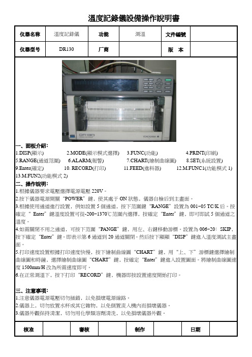
溫度記錄儀設備操作說明書仪器名称溫度記錄儀功能測溫文件編號仪器型号DR130 厂商版本一﹑面板介紹﹕1.DISP(顯示)2.MODE(顯示模式選擇)3.FUNC(功能)4.PRINT(印刷)5.RANGE(通道范圍)6.ALARM(報警)7.CHART(繪制曲線圖)8.SET(系統設置)9.Enter(確定) 10. RECORD(打印) 11.FEED(進料器) 12.M.FUNC1(功能模式1) 13.M.FUN2(功能模式2)二﹑操作說明﹕1.根據儀器要求電壓選擇電源電壓220V。
2.按下儀器電源開關“POWER”鍵﹐使其處于ON狀態﹐儀器自檢后到主畫面。
3.根據使用通道進行設置﹐例如設置5個通道﹐按下范圍鍵“RANGE”設置為001~05 TC/K后。
按確定“Enter”鍵溫度設置可從-200~1370℃范圍內選擇﹐按確定“Enter”鍵﹐即可即試5個通道之溫度。
4.如需關閉不用之通道﹐可按下范圍“PANGE”鍵﹐用左﹑右鍵移動游標。
設置為006~20﹕SKIP﹐按下確定“Enter”鍵。
即表示第6通道到20通道關閉。
然后按下顯顯“DISP”鍵進入溫度測試主畫面。
5.打印速度設置根據打印速度快慢﹐按下繪制曲線圖“CHART”鍵﹐用“上﹑下”游標鍵選擇繪制曲線圖和時鐘﹐選擇繪制曲線圖“CHART”鍵﹐按確定“Enter”鍵進入設置圖面。
將繪制曲線圖速度1500mm/H改為所需速度即可。
6.在正常測溫下﹐按下打印“RECORD”鍵﹐機器即按設置速度開始打印。
三﹑注意事項﹕1.注意儀器電源電壓切勿插錯﹐以免損壞電源線路。
2.儀器上﹐切勿放置水杯或其它雜物﹐以免倒置流入機內而損壞儀器。
3.儀器外觀保持清潔﹐切勿用化學類溶劑清洗﹐以免損壞儀器外觀。
核准審核制作日期。
温度数据记录仪说明书
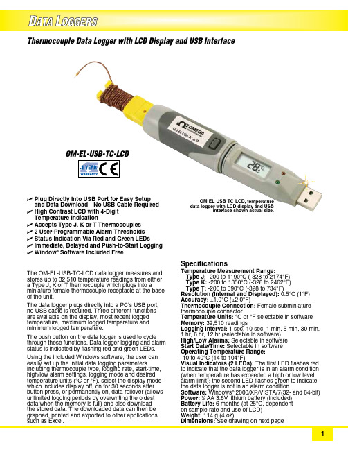
U P lug Directly Into USB Port for Easy Setup and Data Download—No USB Cable RequiredU H igh Contrast LCD with 4‑Digit Temperature IndicationU A ccepts Type J, K or T ThermocouplesU 2 User‑Programmable Alarm ThresholdsU S tatus Indication Via Red and Green LEDsU I mmediate, Delayed and Push‑to‑Start LoggingU Window ® Software Included FreeThe OM‑EL‑USB‑TC‑LCD data logger measures and stores up to 32,510 temperature readings from either a Type J, K or T thermocouple which plugs into a miniature female thermocouple receptacle at the base of the unit.The data logger plugs directly into a PC’s USB port, no USB cable is required. Three different functions are available on the display, most recent logged temperature, maximum logged temperature and minimum logged temperature.The push button on the data logger is used to cycle through these functions. Data logger logging and alarm status is indicated by flashing red and green LEDs.Using the included Windows software, the user can easily set up the initial data logging parameters including thermocouple type, logging rate, start‑time, high/low alarm settings, logging mode and desired temperature units (°C or °F), select the display mode which includes display off, on for 30 seconds after button press, or permanently on, data rollover (allows unlimited logging periods by overwriting the oldest data when the memory is full) and also download the stored data. The downloaded data can then be graphed, printed and exported to other applications such as Excel. Thermocouple Data Logger with LCD Display and USB InterfaceOM-EL-USB-TC-LCDSpecifications Temperature Measurement Range:T ype J: ‑200 to 1190°C (‑328 to 2174°F) Type K: ‑200 to 1350°C (‑328 to 2462°F) Type T: ‑200 to 390°C (‑328 to 734°F)Resolution (Internal and Displayed): 0.5°C (1°F)Accuracy: ±1.0°C (±2.0°F)Thermocouple Connection: Female subminiature thermocouple connector Temperature Units: °C or °F selectable in software Memory: 32,510 readings Logging Interval: 1 sec, 10 sec, 1 min, 5 min, 30 min, 1 hr, 6 hr, 12 hr (selectable in software)High/Low Alarms: Selectable in software Start Date/Time: Selectable in software Operating Temperature Range: ‑10 to 40°C (14 to 104°F)Visual Indicators (2 LEDs): The first LED flashes red to indicate that the data logger is in an alarm condition (when temperature has exceeded a high or low level alarm limit); the second LED flashes green to indicate the data logger is not in an alarm condition Software: Windows ® 2000/XP/VISTA/7(32‑ and 64‑bit)Power: 1⁄2 AA 3.6V lithium battery (included)Battery Life: 6 months (at 25°C, dependent on sample rate and use of LCD)Weight: 114 g (4 oz)Dimensions: See drawing on next pageOM‑EL‑USB‑TC‑LCD, temperature data logger with LCD display and USB interface shown actual size.Ordering Example: OM-EL-USB-TC-LCD , thermocouple data logger with LCD display and USB interface, OCW-3, OMEGACARE SM 3-year extended warranty (adds 3 years to standard 1 year warranty), and OM-EL-BATT replacement battery.Windows ® Software setup screenWindows ® Software shows data in graphical format 134.5 (5.3)69.2 (2.7)56.8 (2.2) 3.5(0.14)2.8(0.11)1.1(0.04) 4.4 (0.174)22.3(0.88)23.9(0.94)24.1(0.95)25.3(0.99)Includes a free 1 m (40") Type K insulated beaded wire thermocouple with subminiature connector and wire spool caddy. Order a Spare! Model No. SC-GG-K-30-36.FREE Thermocouple Included!Dimensions: mm (in)OMEGACARE SM extended warranty program is available for models shown on this page. Ask your sales representative for full details when placing an order. OMEGACARE SM covers parts, labor and equivalent loaners.。
MT温控器说明书完整版

M T温控器说明书 HEN system office room 【HEN16H-HENS2AHENS8Q8-HENH1688】MTC-5080 微电脑温度控制器使用说明产品概述双温度显示,按键直接进入查看、设置参数,多指示灯显示系统运行状态,终端用户脱离说明书方便操作各种功能,无任何复杂的组合和难于理解参数,具备制冷、化霜、风机等功能,适用于对冷库温度的控制。
主要功能温度测量、显示、控制;温度校正;制冷、化霜、风机控制输出;温度超限、超量程及传感器故障报警等。
规格尺寸◇前面板尺寸:100(长)*51(宽)(毫米)◇安装开孔尺寸:92(长)*44(宽)(毫米)◇整机尺寸:100(长)*51(宽)*(深)(毫米)◇传感器线长:2 米(含探头长度)技术参数◇工作电压:220VAC±10% 50HZ/60HZ◇测控温度范围:-50℃~50℃◇测温精度:±1℃显示分辨率:0.1℃◇制冷、化霜、风机输出触点容量:3A/220VAC◇传感器类型:NTC(10Ω /25℃,B 值 3435K)◇工作环境温度:0℃~60℃◇工作环境湿度:20%~85%不可结露面板示意图用户菜单系统菜单用户菜单设置:在运行状态下,按住“设置/查看”键持续 5 秒以上至“显示温度”显示窗显示“SET”时,则表明进入用户菜单设置,“开机温度”指示灯亮,以后每按下并立即松开“设置/查看”键一次,则进入下一项参数设置(可循环操作),相应的参数指示灯亮。
进入用户菜单后,按“▲”或“▼”键可修改“停机温度”显示窗里的设定参数。
系统菜单设置:在运行状态下,同时按住“设置/查看”与“▼”键持续 5 秒以上至“显示温度”显示窗显示“F1”时,则表明进入系统菜单设置,以后每按下并立即松开“设置/查看”键一次,则进入下一项参数设置(可循环操作)。
进入系统菜单后,按“▲”或“▼” 键可修改“停机温度”显示窗里的设定参数。
参数指示灯全灭。
温度数据记录仪产品说明书
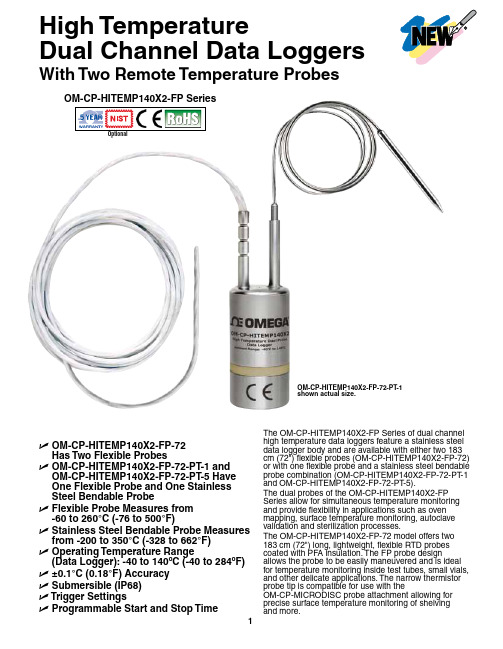
High TemperatureDual Channel Data Loggers With Two Remote Temperature ProbesOptionalU O M-CP-HITEMP140X2-FP-72Has Two Flexible ProbesU O M-CP-HITEMP140X2-FP-72-PT-1 and OM-CP-HITEMP140X2-FP-72-PT-5 HaveOne Flexible Probe and One StainlessSteel Bendable ProbeU F lexible Probe Measures from-60 to 260°C (-76 to 500°F)U S tainless Steel Bendable Probe Measures from -200 to 350°C (-328 to 662°F)U O perating Temperature Range(Data Logger): -40 to 140ºC (-40 to 284ºF) U±0.1°C (0.18°F) AccuracyU S ubmersible (IP68)U T rigger SettingsU P rogrammable Start and Stop Time The OM-CP-HITEMP140X2-FP Series of dual channel high temperature data loggers feature a stainless steel data logger body and are available with either two 183 cm (72") flexible probes (OM-CP-HITEMP140X2-FP-72) or with one flexible probe and a stainless steel bendable probe combination (OM-CP-HITEMP140X2-FP-72-PT-1 and OM-CP-HITEMP140X2-FP-72-PT-5).The dual probes of the OM-CP-HITEMP140X2-FP Series allow for simultaneous temperature monitoring and provide flexibility in applications such as oven mapping, surface temperature monitoring, autoclave validation and sterilization processes.The OM-CP-HITEMP140X2-FP-72 model offers two 183 cm (72") long, lightweight, flexible RTD probes coated with PFA insulation. The FP probe design allows the probe to be easily maneuvered and is ideal for temperature monitoring inside test tubes, small vials, and other delicate applications. The narrow thermistor probe tip is compatible for use with theOM-CP-MICRODISC probe attachment allowing for precise surface temperature monitoring of shelvingOM-CP-HITEMP140X2-FP-72-PT-1shown actual size.The OM-CP-HITEMP140X2-FP-72-PT-1 andOM-CP-HITEMP140X2-FP-72-PT-5 models feature a 61 cm (24") stainless steel bendable probe with the option of either a 2.5 cm (1") or 12.7 cm (5") probe tip (sheath). The stainless steel probe can be bent, angled, and coiled in any direction and formed into position as needed. The sharp probe tip allows for easy insertion and has an extended measurement range of-200 to 350°C (-328 to 662°F).The body of the OM-CP-HITEMP140X2-FP data loggers are capable of operating in temperatures from -40 to 140°C (-40 to 284°F). All models have the capacity to store up to 32,700 time and date stamped readings and feature non-volatile solid state memory that will retain data even if the battery becomesdischarged.The OM-CP-HITEMP140X2-FP utilizes the latest software. The device can be started, stopped, and data can be downloaded quickly and easily. Once in the software, the data can be reviewed in graphic, tabular, or summary form as well as exported to Excel® for further analysis and calculations.The OM-CP-MULTIMOUNTis a versatile mount orstand for use with theOM-CP-HITEMP140 series ofdata loggers. It can be usedto stabilize a logger inside anautoclave, or screwed to aflat surface to create ananchored base. Made of316 stainless steel, theOM-CP-MULTIMOUNTis able to withstandtemperatures up to150°C (302°F) making it ideal for use in autoclavesterilization processes.All modelsshown smallerthan actual size.OM-CP-HITEMP140X2-FP-72OM-CP-HITEMP140X2-FP-72-PT-5OM-CP-IFC400, Windows® software displays datain graphical or tabular format.SPECIFICATIONSTEMPERATURETemperature Sensor:OM-C -HITEM 140X2-F : Flexible RTD probe O M-CP -HITEMP 140X2-FP -P T: Flexible RTD Probe and bendable RTD probeProbe Measurement Range:Flexible Probe: -60 to 260°C (-76 to 500°F) Bendable Probe: -200 to 350°C (-328 to 662°F)Temperature Resolution: 0.01°C (0.02°F)Calibrated Accuracy: ±0.1°C (±0.18°F)GENERALReading Rate: 1 reading every second up to 1 reading every 24 hoursMemory: 32,767 readings Start Modes:• Software programmable immediate start • Delay start up to 18 months in advanceStop Modes: Manual or Timed (specific date and time)Real Time Recording: May be used with PC to monitor and record data in real timePassword Protection: An optional password may beprogrammed into the device to restrict access to configuration options. Data may be read out without the password Readings in Trigger Settings Mode: 16,383 readingsTrigger Settings: High and Low limits may be set. Once data meets or exceed set limits, the device will record to memory. Bi-level start and stop triggers can also be programmed. Users can specify the number of readings to take after the device triggers. (T riggering on channel 1 only)Memory Wrap Around: Y es (software selectable)Battery Type: 3.6V high-temperature lithium battery included; user replaceableBattery Life: 1 year typical [1 minute reading rate at 25°C (77°F)]Calibration: Digital calibration through softwareOM-CP-IFC406 multiplexer data logger interface, shown smaller than actual size (data loggers sold separately).Calibration Date: Automatically recorded within device Data Format: Date and time stamped °C, °F , °R, K Time Accuracy: 1 minute/month @ 25°C (77°F) • 1 minute/month at 25°C (77°F)Computer Interface: OM-CP-IFC400 USB docking station or OM-CP-IFC406 multiplexer interface required; 125,000 baudSoftware: Windows XP SP3/Vista/7 and 8 (32- and 64-bit)Operating Environment: -40 to 140°C (-40 to 284°F), 0 to 100% RH, 0.002 to 100 psia IP Rating: IP68Dimensions (Body): 48 H x 24.6 mm dia (1.89 x 0.97")Dimensions (Probe):OM-C -HITEM 140X2-F -72: Flexible robe: 1829 L x 2.5 mm dia (72 x 0.1") OM-CP-HITEMP140X2-FP-72-PT -1 with 2.5 cm (1") Bendable robe: robe Tip: 42 L x 3.2 mm dia (1.7 x 0.125") Bendable ortion: 559 L x 1.6 mm dia (22 x 0.062") OM-CP-HITEMP140X2-FP-72-PT -5 with 12.7 cm (5") Bendable robe: robe Tip: 121 L x 3.2 mm dia (4.8 x 0.125") with25 L x 4.8 mm dia (1 x 0.188") handle Bendable ortion: 559 L x 1.6 mm dia (22 x 0.062")Weight:OM-C -HITEM 140X2-F -72: 115 g (4.1 oz) OM-C -HITEM 140X2-F -72-T: 110 g (3.9 oz)Materials: Body: 316 stainless steel, PEEK Bendable Probe: 316 stainless steel Flexible Probe: PFA insulated cableOM-CP-MICRODISC surface temperature probe attachment (shown with probepackage and OM-CP-IFC406 multiplexer. OM-CP-IFC400 required for data logger operation. Both models sold separately.Ordering Example: OM-CP-HITEMP140X2-FP-72-CERT high temperature data logger with two 183 cm (72") flexible probes and NIST calibration certificate.To OrderModel No.DescriptionOM-CP-HITEMP140X2-FP-72-PT -5 shown smaller than actual size.。
温度记录仪 中英对照使用说明.

记录仪属性
属性栏 说明如下:
记录仪时钟(Logger's clock)——显示和 设置记录仪当前的时间。
记录仪电量(Logger power)——记录仪当 前电量。
总空间(Total space)—— 记录仪存储数 据的总容量。
记录次数(Recording times)—— 已记录 数据的次数。
标号口令(Type order)—— 说明本记录 仪的标号。
三、其他
其他界面说明:
功能栏 说明如下:
连接(Connection)—— 连接并读取记录仪属性。 参数设置(Parameter setting)—— 设置记录仪参 数。 上传数据(Data upload)——上传记录仪中的历史 数据。 实时数据设置(Real-time collection data setting) —— 设置读取实时数据的采集时间间隔。 实时传输(Start reading real-time data)—— 以 一定时间间隔读取记录仪实时数据(当前采集到的 值)。 实时传输停(Stop reading real-time data)—— 停 止实时传输。 查询数据(Query the history)——可以查询不同单 位不同时段的数据与曲线图和不同温度段的数据。 保存曲线图(Save Graph) —— 把当前显示的曲线 图导入 Word、Excel 文档。 保存数据表(Save Data table) —— 把当前显示的 数据导入 Word、Excel、CSV 文档。 保存至数据库(Save to Database)——保存已下载的 数据到数据库中,保存时会提示你输入单位名称,以 方便数据查询及数据管理。 打印曲线图(Print Graph) —— 打印当前显示的曲 线图。 打印数据表(Print Data table) —— 打印当前显示 的数据表。 完全打印(Print all)——打印当前记录文件显示的 数据及曲线图。注意点击打印的时候使曲线图处于最 大化,这样打印出来的曲线图更清晰。 数据管理(Data management)——可以删除所选单位 名称的数据,也可以清空数据库(清空后数据将无法 恢复)。 停止记录(Stop recording)—— 强制停止记录。 退出(Exit)——退出软件。
- 1、下载文档前请自行甄别文档内容的完整性,平台不提供额外的编辑、内容补充、找答案等附加服务。
- 2、"仅部分预览"的文档,不可在线预览部分如存在完整性等问题,可反馈申请退款(可完整预览的文档不适用该条件!)。
- 3、如文档侵犯您的权益,请联系客服反馈,我们会尽快为您处理(人工客服工作时间:9:00-18:30)。
User's manualMulti-channel temperature recorder(Smart type)08Channels16Channels24Channels32ChannelsFor sales service,please contact your local dealer.ForewordThank you for purchasing our products.In order to ensure that users can use this product correctly, please read this product manual carefully before use.Check the packing list of this manual.Recognize products and accessories.If there is any non-conformity,please contact our company or agent.Precautions1.The contents of this manual are used in conjunction with the instrument,and the contents of the version are subject to change without prior notice.2.The contents of this manual have been confirmed and the user has been able to write the easy-to-understand description of the manual in the simplest way.If you find that it is incorrect or the description is not clear,please contact our company or agent.Version:v1.5WarningFor your personal safety and proper use of this instrument,please be sure to comply with the specification requirements for operation and measure.And pay strict attention to the following safety regulations.1.The Protection of the Power and Grounding.The working power supply of this product is AC86-265V.Before start-up power supply,please confirm the matching between the power supply and the working supply,and ensure that the power supply has been grounded,to prevent electric shock,the instrument shell has received a power outlet wire.2.Please do not operate in an explosive environment,so as to avoid the explosion of personal injury.3.Please do not turn on the instrument shell,the instrument has a high voltage power in some places,to prevent electric shock.4.Do not allow the plug connection in the case of charged,so as to avoid electric shock.5.If the instrument is damaged because of violation of safety rules,the company does not undertake any responsibility.1.SummaryThe multi-channel temperature collector adopts32-bit high-speed cpu for data processing,adopts 5-inch industrial display screen,supports K J E T N S R B type thermocouples input,and various display modes.The user can read various parameters more intuitively,and the instrument has perfect functions.Superior performance and simple operation to meet the needs of production, laboratory and R&D measurement.It is widely used in the production lines,laboratories and quality inspection departments of lighting enterprises,electric tools,household appliances,electric motors,electric appliances, medicine,petroleum,chemical,metallurgy,electric power and other industries and scientific research units.Various measurement functions can be customized to meet higher application requirements. The multi-channel temperature recorder has the following features:▲5-inch industrial color display LCD screen with display resolution up to800x600dbiThe picture is clear,the color is beautiful,and the angle of view is wide.▲32-bit mcu design,more accurate measurement,faster and more stable sampling▲Multi-interface display,support real-time numerical display,time display,column display▲Support multiple sensor inputs:kjetnsrb▲The voltage difference between channels can be as high as ac/dc350v,strong anti-interference ability.▲Each channel can independently set multiple alarm values,ll(ultra low),l(too low),h(too high),hh(super high),and can output alarm through relay.▲Alarm list display,can show the time of occurrence.▲Independent temperature correction△value per channel and cold end value correction.▲Built-in8G large memory,can record up to64files,each file can record60,000sets of data, automatic cycle recording.Support local query history curve.▲With communication address code setting,it can be used inmultiple machines and parallel.It can provide communicationprotocol.▲Standard usb communication interface,optional RS232or RS485communication interface.▲With U disk interface,support U disk to download and copy records.▲Modular design,convenient for users to expand capacity▲8channels per module,this unit supports up to32channels(4modules).2.Basic principleAs shown in the figure,the instrument consists of thermocouple,photoelectric switch selector,amplifier,A/D, single-chip microcomputer,keyboard,display,communication,data memory,cold junction compensation andother components.The corresponding signal channel is selected by the photoelectric switch selector,and the signalis amplified by the signal amplifier,and then the analog signal is converted into a data signal by the ad converter tothe single-chip microcomputer for data processing,and the cold-end compensation circuit performs the normal temperature measurement to obtain the cold.The terminal temperature value,the measurement signal and the cold junction temperature value are processed by the single-chip microcomputer,and finally the correct measured temperature value is displayed on the display screen.The keyboard,communication,and data memory can be usedto analyze and store data on the display.It is also possible to connect the computer directly through the communication interface for data analysis by the computer.3.Technical indicatorsDisplay method5-inch TFT true color LCD industrial screenDisplay form Real-time list value,real-time column chart,real-time graphRecord query The history curve can be queried on this machine.Number of channels8channels per module,up to32channelsK-type thermocouple-100~1370°C Accuracy±0.05°C+0.6°CJ-type thermocouple-100~1200°C Accuracy±0.5°C+0.6°CE-type thermocouple-20~1000°C Accuracy±0.5°C+0.9°CT-type thermocouple-10~40°C Acuracy±0.5°C+0.5°CN-type thermocouple0~1300°C Accuracy±0.5°C+0.9°CS-type thermocouple300~1768°C Accuracy±0.5°C+0.6°CR type thermocouple300~1768°C Accuracy±0.5°C+0.8°CB-type thermocouple400~1820°C Accuracy±0.5°C+1°CResolution0.1℃Recording interval The computer software range is1-9999seconds,and the instrument is1-9999seconds. Communication Interface USB(standard),RS485,RS232(optional)Channel isolation AC/DC power up to350v,superior anti-interference abilityPower supply220V±10%,frequency50Hz/60Hz≤5W(standard),AC86-265V(select)≤5W(optional)4.Panel description (unit:cm)PositiveSide5.Panel descriptionFrontpanel1011.5273033U disk interfaceOperation keyboardSet:Select confirmation keywhen data is setLeft:Use cursor leftRight:Use the cursor to theright Up key:Use the cursor upDown key:Use cursor downPower switchFunction keyboard DisplayRearpanel6.Display and operating instructionsButton descriptionFunction operation keyboard:The function keyboard has a total of 5operation keys,which correspond to the operation function prompted by the display screen.The lowermost one is the interface switching function,which is displayed in sequence:real-time parameter-curve-column chart-recording-Alarm -system has a total of 6interfaces.Data setting keyboard:Data setting keyboard consists of 5buttons,which are set button,left,right,up and down ed in setting the data keyboard and setting the displacement selection.Display interfacedescriptionSetting keyboardFunction keyboardThermocouple Unit Record Cumulative timePerpetual calendar Operate indication zoneInterface information Parameterdisplay area Interface switching indicationBoot LogoThe power-on interface is displayed when power is on,and the company logo,company name,and product model information are displayed.Real-time parameter list displayThe real-time parameter interface can display multiple measurement parameters at the same time.The display interface is divided into4-channel data display and8-channel data display.16-channel data display,page-by-page pagination display,data of each channel,up to four channels of data can be displayed on the4-channel interface,and the measurement alarm status can be displayed.H/HH/L/LL.It is also possible to record the measured maximum and minimum Values.Real-time curveThe real-time curve is only displayed in real time.One page can only display8-channel curves.The real-time temperature value and corresponding channel number can also be displayed on the left side,possibly usingThe key switches another set of8-channel curves.press The key can enter the curve parameter settingsRecording curveThe recording curve is a real-time curve displayed when the recording is started,and can also be operated.Press the button to balance the movement of the curve.The recording symbol of this interface is displayed,the accumulated time will be accumulated.Historical curveThe historical curve is page-turnable,but it cannot be set.Only the total curve of the entire file can be displayed.Real-time column chartBy using the histogram method,the ratio of each channel can be compared.In the4-column chart,the actual difference between the two channels can be automatically calculated.Value,the actual measured temperature value can also be displayed in the4and8bar chartsNote:The y-axis display temperature range is the same as the curve setting range and is only set in the curve settings.Use to switch4/8/16channel display e can display multi-page parameters.Curve setting interfaceThe curve setting boundary includes a curveThe x-axis plot time,the range of the y-axis curve display,and the display curve channel can also be displayed or masked.Note:The curve time display value cannot be modified when the recording has been started.Recording interfaceStart/stop recording button.When the start button is pressed,the“Continue to continue”interface will pop up. When“Yes”is selected,the recording will be executed,the recording symbol will become,the time will startto accumulate,and the time will be counted.stop.Record settingRecord interval setting,the setting range is1-9999seconds.File formatting is to format all current log files,and all records can be erased after formatting.File export,this operation is to directly import all the records into the u disk at a time.Then import it from the PC software of pc.Perform data analysis.The recorded files support u disk export,and also support direct connection pc export.Alarm settingIn the alarm interface,you can view all current alarm status information,and you can view the page when multiple recordings.Alarm value settingIn these interfaces,you can directly set the super high value(HH)\too high value(H)\too low value(L)\Ultra low value(LL).You can use the operation keyboard to move the cursor directly to select the pop-up data keyboard for numerical setting.System settingThe system settings provide a rich set of menus that are clear and easy to use.Provided date and time, measurement speed,display language,unit of measure,sensor type,buzzer sound,communication place Address, communication baud rate,backlight time(0is long light,1-999seconds to turn off the backlight).Note:The time and date,measurement speed,unit of measure,and sensor cannot be changed when the recording is started.△value correction settingThis interface provides a correction setting for each channel△v alues,and can display the current measured temperature values for each channel,in the end the change value,can see the changes of the current value of real time,can be corrected to the actual measured value.The need to change,press the Enter key,each channel△value position can be changed into numerical red,press the arrow keys to one decimal place and,according to the left and right keys to add and subtract in bits.7.Software operating instructionsFind files in U disk Run the installation directly,as followsAfter the installation is completed,then the USB driver installation After installation,see one on the desktop Icon,Click this icon to run the software program.Enter boot interfaceThe first connection between the computer and the instrument,install the driver in the file list,and then choose the correct COM in the soft interface,the main interface in the lower left corner of the communication connection is successful.Computer interface provides a wealth of display and analysisfunctions,you can display a list of files,curve analysis shows that the list of data,real-time temperature list, instrument operation button functionList of documents are listed:serial number,record time,file name,the number of data,a large number of filesCurve labels can be detailed analysis of all the data in the file,You can use the mouse directly to zoom in and out of the curveYou can change the color of each channel in the curveYou can customize the name for each channelThe list of data can be displayed for each channel and each time interval.The user can directly open the*.CSV file directly with the EXCEL.Real time data list can display the current measured value in realThe instrument can be used directly to the remote operation of the button page.Verification conditionProject Reference ratio or range Reference ratio or range Ambient temperature℃20±5Ambient humidity RH45~75Atmospheric pressure KPa86~106AC supply voltage V220or86-265±2% AC power supply frequency Hz50±1%AC power supply waveform Sine waveß=0.05External electromagneticinterference Should avoidAeration Good ventilationSunlight exposure Avoid directPacking listHost1PCSPower cord1PCSUse manual1PCS Certificate of conformity Warranty card1PCS Thermocouple wire1PCSProduct certificateProduct name:Multichannel temperature recorderProduct model:Product number:Date:Examination clerk:Verification conclusion:Product warranty card●Warranty description:1.Warranty period within24months from the date of purchase2.Warranty equipment in the warranty period,in the normal use and maintenance of the case,the instrument problems,after inspection,the company will provide free repair and replacement parts.●The following conditions are not free maintenance1products from the company's technical personnel to repair,change,modification,the userto replace any of the internal parts.2serial number has been altered or inconsistent with the specified3damage caused by the infiltration of water or other substances into the machine●The company may also provide maintenance services,which require more than a free warrantyName ModelTel Purchase dateAddress NumberOverhaul date Maintenance record Maintenance man。