ATMEGA103-6AC,ATMEGA103-6AI, 规格书,Datasheet 资料
ATmega103_603
R31
$1F
Z 寄存器高字节
所有的寄存器操作指令都可以单指令的形式直接访问所有的寄存器 例外情况为 5 条涉及常 数操作的指令 SBCI SUBI CPI ANDI 和 ORI 这些指令只能访问通用寄存器文件的后 半部分 R16 到 R31 如图 5 所示 每个寄存器都有一个数据内存地址 将他们直接映射到用户数据空间的头 32 个地址 虽然寄存器文件的实现与 SRAM 不同 这种内存组织方式在访问寄存器方面具有 极大的灵活性 X Y Z寄存器 寄存器 R26~R31 除了用作通用寄存器外 还可以作为数据间接寻址用的地址指针
第2页共2页
ATmega603/103
B 口 PB7…PB0 B口是一个 8 位双向 I/O 口 每一个管脚都有内部上拉电阻 B口的输出缓冲器能够吸收 20mA 的电流 可直接驱动 LED 当作为输入时 如果外部被拉低 由于上拉电阻的存在 管脚 将输出电流 在复位过程中 B 口为三态 即使此时时钟还未起振 B 口作为特殊功能口的使用方方法见以后章节 C 口 PC7…PC0 C 口是一个 8 位输出 I/O 口 能够吸收 20mA 的电流 在访问外部 SRAM 时 C 口作为地址线 在复位过程中 C 口不为三态 D 口 PD7…PD0 D 口是一个带内部上拉电阻的 8 位双向 I/O 口 输出缓冲器能够吸收 20mA 的电流 当作为 输入时 如果外部被拉低 由于上拉电阻的存在 管脚将输出电流 在复位过程中 D 口为 三态 即使此时时钟还未起振 D 口作为特殊功能口的使用方方法见以后章节 E 口 PE7…PE0 E 口是一个带内部上拉电阻的 8 位双向 I/O 口 输出缓冲器能够吸收 20mA 的电流 当作为 输入时 如果外部被拉低 由于上拉电阻的存在 管脚将输出电流 在复位过程中 E 口为 三态 即使此时时钟还未起振 E 口作为特殊功能口的使用方方法见以后章节 F 口 PF7…PF0 F 口是一个 8 位输入 I/O 口 也可作为 ADC 的模拟输入 /RESET 复位输入 超过 50ns 的低电平将引起系统复位 低于 50ns 的脉冲不能保证可靠 复位 XTAL1 振荡器放大器的输入端 XTAL2 振荡器放大器的输出端 TOSC1 RTC 振荡器放大器的输入端 TOSC2 RTC 振荡器放大器的输出端 /WR 外部 SRAM 写信号 /RD 外部 SRAM 读信号 ALE 访问外部存储器时的地址锁存使能信号 用于锁存低 8 位地址 AVCC A/D 转换器的电源 应该通过一个低通滤波器与 VCC 连接 AREF A/D 转换器的参考电源 介于 AGND 与 AVCC 之间 AGND 模拟地 /PEN 串行下载的编程使能信号 晶体振荡器 XTAL1 和 XTAL2 分别是片内振荡器的输入 输出端 可使用晶体振荡器或是陶瓷振荡器 当使用外部时钟时 XTAL2 应悬空
稳压管参数——精选推荐

单片机解密承接单片机项目开发单片机解密电子产品设计本公司提供的MCU单片机解密服务,解密型号涵盖了51系列MCU,PIC系列MCU和AVR系列MCU在内的各系列单片机。
一、MCS-51系列单片机MCS-51系列单片机是目前国内应用最为广泛的单片机系列之一,常见的主要有ATMEL、WINBOND、SYNMOS和PHILIP等,其中又以ATMEL的51系列单片机的应用最为广泛。
随着51系列单片机在国内的广泛应用,相应的单片机解密技术也有了较大的发展。
考虑到目前市场的需求,本公司采用传统的方法对广大客户提供51单片机解密(仅限合法研究用途),部分解密的单片机型号如下:公司名称单片机解密型号ATMEL AT89C51 AT89C52 AT89S51 AT89S52AT89C55 AT89C55WD A T89C51RC AT89C2051AT89C4051 A T89S8252 其它未列型号WINBOND W78E51 W78E51B W78E52 W78E58BW78E54 W78E54B W78E58 W78E78BW78E516 W78E516B W77E58 W77E516其它未列型号SYNCMOS SM8951 SM8951A SM8952 SM8952ASM8954 SM8954A SM8958 SM8958ASM89S16 SM89516A 其它未列型号PHILIPS P87LPC764 P87LPC762 P89C51B P89C52BP89C54B P89C58B P89C51X2 P89C52X2P87C51X2 P87C52X2 P87LPC932 其它未列型号二、AVR系列单片机解密AVR系列单片机是1997年ATMEL公司为了充分发挥其Flash的技术优势,而推出的全新配置的精简指令集(RISC)单片机,简称AVR。
该系列单片机一进入市场,就以其卓越的性能,而大受欢迎。
通过这几年的发展,AVR单片机已形成系列产品,其Attiny系列、AT90S系列与Atmega系列分别对应为低、中、高档产品(高档产品含JTAG ICE仿真功能)。
电能计量元器件
本科毕设:不要求通信,只需要计算出用电器的电能,并在LCD上面进行显示,结合灯光控制来做。
硬件电路:ATmega16单片机,电流互感器,电压互感器,电能计量芯片,
电能计量芯片:电能计量芯片根据其内部的瞬时电压和瞬时电流计算瞬时功率,再输出脉冲驱动机械式计数器或者步进电机计算用电电量。
电能计量专用芯片:CS546OA,具有片内看门狗定时器与内部电源监视器;具有瞬时电流、瞬时电压、瞬时功率、电流有效值、电压有效值、功率有效值测量及电能计量功能;提供了外部复位引脚(这个地方可以重新进行计数);双向串行接口与内部寄存器阵列可以方便地与微处理器相连接;外部时钟最高频率可达20MHz;具有功率方向输出指示。
这些增加的功能更加便于与微控制器接口,并能方便地实现电压、电流、功率的测量和用电量累积等功能。
据此选择CS5460A作为电能计量芯片更能实现各种电参数的测量。
atmega32a 模数转换 电压范围

Atmega32a模数转换电压范围1. 介绍Atmega32a是一款由Microchip(前身为Atmel)开发的8位微控制器。
它具有强大的功能和广泛的应用领域,其中之一就是模数转换(ADC)。
模数转换是将连续变化的模拟信号转换为相应的数字信号的过程。
在嵌入式系统中,ADC起着至关重要的作用,因为它允许我们将外部传感器测量到的模拟信号转换为数字形式,以便进行数据处理和分析。
Atmega32a提供了一个强大且灵活的ADC单元,可以满足各种应用需求。
在本文中,我们将重点介绍Atmega32a的ADC功能以及其支持的电压范围。
2. Atmega32a ADC概述Atmega32a具有一个12位逐次逼近型ADC单元,可以进行单通道或多通道模拟信号采样。
它具有以下主要特征:•支持8个输入通道:ADC0-ADC7。
•可配置参考电压源:内部参考电压、外部参考电压或AVCC引脚。
•可选择不同采样速率和分辨率。
•可以通过软件或硬件触发ADC转换。
•支持左对齐或右对齐的结果。
•可以通过中断或轮询方式读取ADC结果。
3. Atmega32a ADC电压范围Atmega32a的ADC电压范围取决于所选的参考电压源。
它可以使用以下三种参考电压源之一:3.1 内部参考电压源Atmega32a具有一个内部2.56V的参考电压源,称为Internal Voltage Reference (Vref)。
使用内部参考电压源时,ADC的电压范围为0V至2.56V。
这种模式下,可以通过设置ADMUX寄存器的REFS位来选择内部参考电压源。
3.2 外部参考电压源Atmega32a还可以使用外部参考电压源作为ADC的参考。
外部参考电压通常由外部稳定器提供,并且可以在0V至5V之间变化。
在这种模式下,ADC的电压范围将与外部参考电压相同。
要使用外部参考电压源,需要将REFS位设置为“01”或“10”,并将AREF引脚连接到外部稳定器提供的参考电压。
ATmega16中文数据手册
4
ATmega16(L)
2466G–AVR–10/03
Hale Waihona Puke ATmega16(L)端口 D(PD7..PD0) 端口 D 为 8 位双向 I/O 口, 具有可编程的内部上拉电阻。其输出缓冲器具有对称的驱动特 性,可以输出和吸收大电流。作为输入使用时,若内部上拉电阻使能,则端口被外部电路 拉低时将输出电流。在复位过程中,即使系统时钟还未起振,端口 D 处于高阻状态。 端口 D 也可以用做其他不同的特殊功能,请参见 P61。 RESET XTAL1 XTAL2 AVCC AREF 复位输入引脚。持续时间超过最小门限时间的低电平将引起系统复位。门限时间见 P36Table 15。持续时间小于门限间的脉冲不能保证可靠复位。 反向振荡放大器与片内时钟操作电路的输入端。 反向振荡放大器的输出端。 AVCC 是端口 A 与 A/D 转换器的电源。 不使用 ADC 时, 该引脚应直接与 VCC 连接。 使用 ADC 时应通过一个低通滤波器与 VCC 连接。 A/D 的模拟基准输入引脚。 本数据手册包含了一些简单的代码例子以说明如何使用芯片各个不同的功能模块。这些 例子都假定在编译之前已经包含了正确的头文件。有些 C 编译器在头文件里并没有包含 位定义,而且各个 C 编译器对中断处理有自己不同的处理方式。请注意查阅相关文档以 获取具体的信息。
SPI
USART
+ -
COMP. INTERFACE
PORTB DIGITAL INTERFACE
PORTD DIGITAL INTERFACE
PORTB DRIVERS/BUFFERS
PORTD DRIVERS/BUFFERS
PB0 - PB7
PD0 - PD7
3
CS497 Course Report on PMRT WSN Design

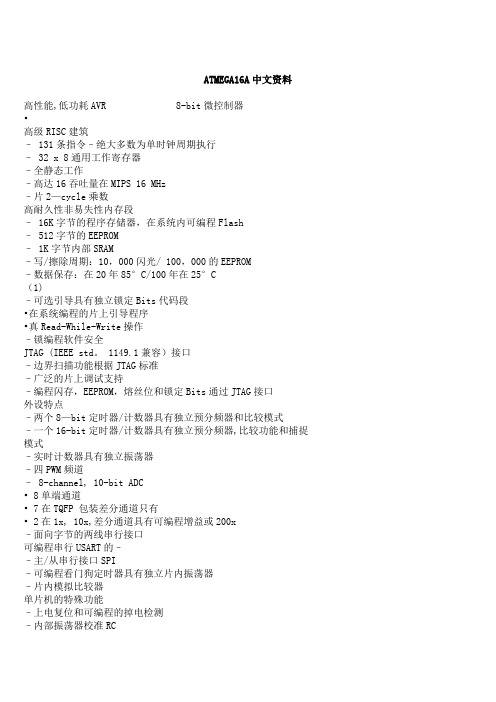
CS497Course Report on PMRT WSN DesignQixin WangInstructor:Prof.Marco CaccamoDecember,2002First,we study the system architecture of sensor devices and their networks.Based on the system architecture,we analyze the constraints on sensing frequency selections,so that real-time schedulability criterions are met.Specifically,we study the sensor network of UC Berkeley mica motes [5][3],which uses ATmega103L micro-controllers [2].Fig 1is an illustration of the infrastructure of an ATmega103L mote with wirelesscommunication module.The CPU,main memory and data busetc.are all integrated in the ATMega103L micro-controller.TheCPU clock frequency is 4MHz.One important peripheral to theATMega103L micro-controller is the RFM™TR1000[6]wireless co-processor (named as “Radio CoPU”in Fig 1),whichcontrols the wireless communication physical layer –the916.5MHz radio channel.The CPU communicates with theRadio CoPU using clock driven periodical querying –thequerying rate is 20kHz for receiving and 10kHz for sending.I.e.when the system is in radio receiving mode,there are exactly4MHz/20kHz=200CPU cycles between each two consecutiveradio CoPU queries;and when in sending mode,there are4MHz/10kHz=400CPU cycles between each two consecutiveradio CoPU queries.This design successfully enables ATMega103L mote with a 500Byte/sec application layer transmission rate [4].The success of mote’s design supports the practicability of a slightly more complex system architecture –Parallel Multiple hard Real-Time (PMRT)wireless sensor device,illustrated by Fig2.Fig 1Mote InfrastructureIn this architecture,there can be several Radio CoPUs operating at different radio frequencies,each one functions either as a receiver or a sender (note:there can be several senders in one host,though Fig 2only shows one).Each sender sends its packets according to Non-preemptive EDF .And every sender has a dedicated EDF Scheduling Pool 1in the main memory to buffer/schedule its outgoing packets.The CPU accesses each receiver/sender by clock driven periodical querying.After each query,the CPU execute the following routings:Routine 1:After queried a receiver:1.Assemble the newly received bit in the memory buffer according to the query result.2.If the bit is the last bit of a byte,assemble a newly received byte.3.If the byte is the last byte of a packet,insert the packet to the right position of the right sender’s EDF Scheduling Pool.Routine 2:After queried a sender:1.Pick the next bit-to-send from the current packet-to-send in the sender’s EDF Scheduling Pool.This bit is the bit to give to the sender in the next query.2.If the last bit of the current-packet-to send is already sent to sender,pick the next packet-to-send from the EDF Scheduling Pool as the new current packet-to-send and goto 1.3.If there is no next packet-to-send,the corresponding sender becomes idle in the next query cycle.First look at the inner-host schedulability.Suppose 21,Routine Routine C C are the worst case execution time (in the units of “CPU cycles”)for Routine 1and Routine 2respectively.Suppose R is the set of all receivers on the host and S is the set of all senders on the host.For a specific R ∈receiver the bandwidth is receiver B ,and for a specific S ∈sender ,1Sometimes is also called Scheduling Queue .But Pool is a more proper word since the behavior may be much more complicated than Queue ’s first-in-first-outbehavior.Fig 2A Future Design of Multi-channel Mote (e.g.,with 6Rec Channels and 1SendingChannel)the bandwidth is sender B (all are in the unit of “bits per second”).Let receiver k be the number of CPU queries to receive one bit on receiver and sender k be the number of CPU queries to send one bit on sender .Let CPU C to be the total CPU cycles available each second (i.e.in the unit of “CPU cycles per second”).Then the schedulability constraint set by the internal architecture of the host is (remember the internal CPU uses clock driven periodical scheduling):(1)21CPU sender Routine sender sender receiver Routine receiver receiver C C B k C B k ≤+∑∑∈∈S R I.e.,if none of the receivers/senders are overloaded (on their bandwidths),inner-host schedulability is always guaranteed .The manufacturers of PMRT wireless sensor devices should specify B receiver and B sender according to (1).The inter-host schedulability constraint analysis is as follows:In order to make things simple,we allow only one sender for each channel.On the other hand,a channel can have one (as shown by the shaded area in Fig 3(a))or multiple (as shown by the shaded area in Fig 3(b))receivers (where packet’s receiver address is used to distinguish the effective receiver).No matter how many receivers are there in a channel,the bandwidth of a channel B (in bps)is defined as the maximal affordable bit rate that the sender,anyone of the receivers and the receiver’s corresponding bit dispatcher (i.e.,the internal CPU and Memory that runs Routine1)can handle.Let’s first look at the EDF Scheduling Pool of the sender of a channel.Suppose T is the set of connections (tasks)that need to go through this sender.For a connection (or say,in real-time’s jargon –a task)T ∈τ,suppose it has a reporting frequency of τf(reportFig 3(a)Channel with SingleReceiver Fig 3(b)Channel with Multiple Receiverpackets per second)and a report packet length of τl .Then each of its report,if there is no any other connections contending,should be sent to the receiver and dispatched to thereceiver hop’s corresponding EDF Scheduling Pool in time Bl τ.However,the physical channel media is a non-preemptive resource.I.e.,if one packet started transmitting,it can not be preempted by any other packet until it is completely transmitted.Hereby,the real-time scheduler of EDF Scheduling Pool should be a Nonpreemptive EDF scheduler ,to ensure both the EDF behavior and non-preemptive usage of the channel’s physical media.Accordingly,the fine grain sufficient schedulability bound for the scheduler should be the following inequality system defined in [1].Reference:[1]G.C.Buttazzo,Hard real-time computing systems:predictable scheduling algorithm and applications,Kluwer Academic Publishers,1997[2]D.V.Gadre,Programming and Customizing the AVR Microcontroller,McGraw-Hill,2001[3]Jason Hill,Robert Szewczyk,Alec Woo,Seth Hollar,David E.Culler,Kristofer S.J.Pister,System Architecture Directions for Networked Sensors,in Proc.of ASPLOS-IX,Cambridge,Mass.2000[4]Qixin Wang,Mote’s throughput test report and source code,in/~weizhang/wsn/documents.html[5]B.Warneke,B.Atwood,K.S.J.Pister,``Smart Dust Mote Forerunners,''in Proc.of the Fourteenth Annual International Conference on Microelectromechanical systems (MEMES 2001),Interlaken,Switzerland,Jan.21-25,2001,pp.357-360.[6]/datasheet/tr1000.pdf。
上海沪生电子产品 USB酷鱼下载线 说明书

上海沪生电子产品使用说明书电话:************网站:第一章 ISP介绍关于isp下载技术ISP(In-System Programming)在系统可编程,指电路板上的空白器件可以编程写入最终用户代码,而不需要从电路板上取下器件,已经编程的器件也可以用ISP方式擦除或再编程。
无论在单片机上,还是在CPLD/FPGA上都得到了广泛的应用,ISP技术是未来发展方向!回忆下传统的编程方式,举设计单片机系统为例,如果想要对单片机编程序,必须要把单片机先从电路板上取下来,然后放入专用的编程器进行编程,最后再次放入电路板进行调试,可以看出,这样的开发步骤有以下缺点:1)频繁的拔插芯片,容易损坏芯片的引脚;2)如果频繁的调试程序,换程序,必须重复拔插,大大降低了开发效率。
isp技术彻底地改变了传统的开发模式,它只要在电路板上留下个接口(如ispdown的十芯插座),配合ispdown的下载电缆,就可以不用拔出芯片,在电路板上就可以对芯片进行编程,对比传统的开发系统,有以下优势:1)工程师在开发电子系统时彻底告别频繁拔插芯片的噩梦,避免损坏芯片的引脚;2) ISP 可以加速产品的上市并降低研发成本。
3)ISP技术帮助工程师缩短从设计、制造到现场调试、简化生产流程并采用经证实更有效的方式进行现场升级和维护,大大提高了工作效率。
4)在试验新品或学生试验等经常需要用不同的程序调试芯片的场合中,在线编程技术尤为重要。
而以上这些还只是 ISP 技术所能为你带来的一部分好处。
一.第二章酷鱼下载线快速使用产品特性1)USB接口,U盘封装,轻巧高档,非常适合手提电脑使用和野外调试使用。
黑色高贵,尽显魅力。
2)支持芯片多:支持大部分清爽II型下载线的单片机编程下载,如ATMEL89,AT90s,ATMEGA,PIC 等;支持24CXX存储器,系统要求:WINDOWS各版本都可!支持uADU800系列芯片;3)酷鱼本身如果不作为下载线使用,更可以做为USB转串口模块使用,把您原来的串口设备一步升级到USB,不用改变上位机程序,下位机程序!二.配件说明标准配置:主机一台10芯下载线一根说明书一份光盘一张选配:USB转RS232板一块二.安装指南本产品稳定运行于WINDOWS系统的各个平台,在插入USB酷鱼下载线之前,请(1)首先安装驱动程序.驱动程序位置:您可以(1)光盘\CoolFishDrv\驱动程序\coolfishdrv\PreInstaller.exe,双击运行.也可以(2)从网站下载: /SoftView.asp?SoftID=203,解压后找到PreInstaller.exe,双击运行.(2)安装好驱动程序后,请插入硬件,在WIN2000,WIN98系统下,硬件将会自动安装.在XP系统以上,将提示安装驱动程序,请参考视频教程,位置: (1)光盘\视频\ installDRV.swf,或者下载(2)/describe.asp?id=159.三.硬件安装联机示意图如下10芯下载线说明图如下上图是整体图片.三.软件操作规程.(1)硬件联机后,首先要检测端口,如下图当端口检测成功,信息框将会有相应提示. 当连接成功后,信息提示框将提示端口号,并把该信息记录在数据库,如果不更换计算机和下载线,下次重新开启软件时,不需要再次检测.(2)对芯片进行下载,必须确定被操作的芯片.当对单片机进行下载时,课点击如左图按钮自动搜索目标芯片当对24CXX存储器进行编程时,软件无法自动识别,必须进行手动指定.点击菜单”芯片识别->手动选择..”,出现下图后进行选择.(3)打开FLASH或者EEPROM文件(4)点击”自动编程”或者按”F9”功能键完成下载编程四.接口汇总支持器件列表:AT系列可ISP单片机(Atmel公司)1.AT89LS51,AT89S51,AT89LS52,AT89S52.2.AT90CAN128,AT90S1200,AT90S2313,AT90S2323,AT90LS2323,AT90S2333,AT90LS2333,AT90S2343,AT90LS2343,AT90S4414,AT90S4433,AT90LS4433,AT90S4434,AT90LS4434,AT90S8515,AT90S8535,AT90LS85353.A TMEGA103,ATMEGA103L,A TMEGA128,A TMEGA128L,A TMEGA16,A TMEGA16L,A TMEGA161,ATMEGA161L,ATMEGA162,ATMEGA162V,A TMEGA163,ATMEGA163L,ATMEGA168,A TMEGA169,A TMEGA169V,A TMEGA32,ATMEGA32L,ATMEGA323,ATMEGA323L,ATMEGA48,A TMEGA64,ATMEGA64L,ATMEGA8,ATMEAG8L,ATMEGA8515,A TMEGA8515L,A TMEGA8535,A TMEGA8535L,A TMEGA884.ATTINY12,ATTINY12L,ATTINY13,ATTINY15L,ATTINY2313,ATTINY2313V,ATTINY26,ATTINY26LPIC系列可ISP单片机5.PIC16F870,PIC16F871,PIC16F872,PIC16F873,PIC16F873A,PIC16F874,PIC16F874A,PIC16F876,PIC16F876A,PIC16F877,PIC16F877AAduC系列通过串口进行ISP之单片机6.ADUC812,ADUC812S,ADUC814,ADUC816,ADUC824,ADUC824B2,ADUC831,ADUC832,ADUC834,ADUC836,ADUC841,ADUC842,ADUC843,ADUC844,ADUC845,ADUC846,ADUC847,ADUC84824Cxx系列EEPROM存储器7.24C02A/24LC02A,24C04A/24LC04A,24C08A/24LC08A,24C16A/24LC16A,24C32A/24LC32A,24C64A/24LC64A,24C128A/24LC128A,24C256A/24LC256A单片机通过4条线, 24Cxx系列EEPROM存储器通过2条线即可实现免拔插实现在线更新数据,适用范围:单片机开发,家电维修.第三章安装步骤1.检测配件是否齐全(USB下载线1个,ISP线1条,USB转串口电路板1块).2.不要把USB下载线插入电脑中,先安装配套光盘中的驱动程序(亦可到本网站下载), 在配套光盘中找到CoolFishDrv文件夹下的PreInstaller.exe文件,双击安装,具体安装方法可参考到本网站查看installDRV.rar视频教程.当出现以下信息提示,即表明驱动程序安装完毕。
ATMEGA16A中文资料
ATMEGA16A中文资料高性能,低功耗AVR 8-bit微控制器•高级RISC建筑– 131条指令–绝大多数为单时钟周期执行– 32 x 8通用工作寄存器–全静态工作–高达16吞吐量在MIPS 16 MHz–片2—cycle乘数高耐久性非易失性内存段– 16K字节的程序存储器,在系统内可编程Flash– 512字节的EEPROM– 1K字节内部SRAM–写/擦除周期:10,000闪光/ 100,000的EEPROM–数据保存:在20年85°C/100年在25°C(1)–可选引导具有独立锁定Bits代码段•在系统编程的片上引导程序•真Read-While-Write操作–锁编程软件安全JTAG (IEEE std。
1149.1兼容)接口–边界扫描功能根据JTAG标准–广泛的片上调试支持–编程闪存,EEPROM,熔丝位和锁定Bits通过JTAG接口外设特点–两个8—bit定时器/计数器具有独立预分频器和比较模式–一个16-bit定时器/计数器具有独立预分频器,比较功能和捕捉模式–实时计数器具有独立振荡器–四PWM频道– 8-channel, 10-bit ADC• 8单端通道• 7在TQFP 包装差分通道只有• 2在1x, 10x,差分通道具有可编程增益或200x–面向字节的两线串行接口可编程串行USART的––主/从串行接口SPI–可编程看门狗定时器具有独立片内振荡器–片内模拟比较器单片机的特殊功能–上电复位和可编程的掉电检测–内部振荡器校准RC–外部和内部中断源– 6种睡眠模式:空闲,ADC降噪,省电,省电,待机和扩展待机I / O和封装– 32可编程I / O线– 40—pin PDIP, 44—lead TQFP,和44—pad QFN/MLF 工作电压– 2。
7为- 5。
5V ATmega16A速度等级– 0 —为16 MHz ATmega16A功耗@ 1 MHz, 3V,和25°C为ATmega16A–活动:0。
- 1、下载文档前请自行甄别文档内容的完整性,平台不提供额外的编辑、内容补充、找答案等附加服务。
- 2、"仅部分预览"的文档,不可在线预览部分如存在完整性等问题,可反馈申请退款(可完整预览的文档不适用该条件!)。
- 3、如文档侵犯您的权益,请联系客服反馈,我们会尽快为您处理(人工客服工作时间:9:00-18:30)。
1Features•Utilizes the AVR ® RISC Architecture•AVR – High-performance and Low-power RISC Architecture–121 Powerful Instructions – Most Single Clock Cycle Execution–32 x 8 General Purpose Working Registers + Peripheral Control Registers –Up to 6 MIPS Throughput at 6 MHz •Data and Nonvolatile Program Memory–128K Bytes of In-System Programmable FlashEndurance: 1,000 Write/Erase Cycles –4K Bytes Internal SRAM–4K Bytes of In-System Programmable EEPROMEndurance: 100,000 Write/Erase Cycles–Programming Lock for Flash Program and EEPROM Data Security –SPI Interface for In-System Programming •Peripheral Features–On-chip Analog Comparator–Programmable Watchdog Timer with On-chip Oscillator –Programmable Serial UART–Master/Slave SPI Serial Interface–Real-time Counter (RTC) with Separate Oscillator–Two 8-bit Timer/Counters with Separate Prescaler and PWM–Expanded 16-bit Timer/Counter System with Separate Prescaler, Compare, Capture Modes and Dual 8-, 9-, or 10-bit PWM–Programmable Watchdog Timer with On-chip Oscillator –8-channel, 10-bit ADC•Special Microcontroller Features–Low-power Idle, Power-save and Power-down Modes –Software Selectable Clock Frequency –External and Internal Interrupt Sources •Specifications–Low-power, High-speed CMOS Process Technology –Fully Static Operation•Power Consumption at 4 MHz, 3V , 25°C –Active: 5.5 mA –Idle Mode: 1.6 mA–Power-down Mode: < 1 µA •I/O and Packages–32 Programmable I/O Lines, 8 Output Lines, 8 Input Lines –64-lead TQFP •Operating Voltages–2.7 - 3.6V for ATmega103L –4.0 - 5.5V for ATmega103•Speed Grades–0 - 4 MHz for ATmega103L –0 - 6 MHz for ATmega1038-bit Microcontroller2ATmega103(L)0945I–AVR–02/07Pin ConfigurationTQFP3ATmega103(L)0945I–AVR–02/07DescriptionThe ATmega103(L) is a low-power, CMOS, 8-bit microcontroller based on the AVR RISC architecture. By executing powerful instructions in a single clock cycle, the ATmega103(L) achieves throughputs approaching 1 MIPS per MHz, allowing the sys-tem designer to optimize power consumption versus processing speed.The AVR core is based on an enhanced RISC architecture that combines a rich instruc-tion set with 32 general purpose working registers. All the 32 registers are directly connected to the Arithmetic Logic Unit (ALU), allowing two independent registers to be accessed in one single instruction executed in one clock cycle. The resulting architec-ture is more code efficient while achieving throughputs up to ten times faster than conventional CISC microcontrollers.The ATmega103(L) provides the following features: 128K bytes of In-System Program-mable Flash, 4K bytes EEPROM, 4K bytes SRAM, 32 general purpose I/O lines, 8 input lines, 8 output lines, 32 general purpose working registers, Real Time Counter (RTC), 4flexible Timer/Counters with compare modes and PWM, UART, programmable Watch-dog Timer with internal Oscillator, an SPI serial port and 3 software-selectable power saving modes. The Idle mode stops the CPU while allowing the SRAM, Timer/Counters,SPI port and interrupt system to continue functioning. The Power-down mode saves the register contents but freezes the Oscillator, disabling all other chip functions until the next Interrupt or Hardware Reset. In Power-save mode, the Timer Oscillator continues to run, allowing the user to maintain a timer base while the rest of the device is sleeping.The device is manufactured using Atmel’s high-density nonvolatile memory technology.The On-chip ISP Flash allows the Program memory to be reprogrammed In-System through a serial interface or by a conventional nonvolatile memory programmer. By combining an 8-bit RISC CPU with a large array of ISP Flash on a monolithic chip, the Atmel ATmega103(L) is a powerful microcontroller that provides a highly flexible and cost-effective solution to many embedded control applications.The ATmega103(L) AVR is supported with a full suite of program and system develop-ment tools including: C compilers, macro assemblers, program debugger/simulators, In-Circuit Emulators and evaluation kits.4ATmega103(L)0945I–AVR–02/07Block DiagramFigure 1. The ATmega103(L) Block Diagram5ATmega103(L)0945I–AVR–02/07Pin DescriptionsVCC Supply voltage.GNDGround.Port A (PA7..PA0)Port A is an 8-bit bi-directional I/O port. Port pins can provide internal pull-up resistors (selected for each bit). The Port A output buffers can sink 20 mA and can drive LED dis-plays directly. When pins PA0 to PA7 are used as inputs and are externally pulled low,they will source current if the internal pull-up resistors are activated.Port A serves as Multiplexed Address/Data bus when using external SRAM.The Port A pins are tri-stated when a reset condition becomes active, even if the clock is not running.Port B (PB7..PB0)Port B is an 8-bit bi-directional I/O port with internal pull-up resistors. The Port B output buffers can sink 20 mA. As inputs, Port B pins that are externally pulled low, will source current if the pull-up resistors are activated.Port B also serves the functions of various special features.The Port B pins are tri-stated when a reset condition becomes active, even if the clock is not running.Port C (PC7..PC0)Port C is an 8-bit output port. The Port C output buffers can sink 20 mA.Port C also serves as Address output when using external SRAM.Since Port C is an output only port, the Port C pins are not tri-stated when a reset condi-tion becomes active.Port D (PD7..PD0)Port D is an 8-bit bi-directional I/O port with internal pull-up resistors. The Port D output buffers can sink 20 mA. As inputs, Port D pins that are externally pulled low will source current if the pull-up resistors are activated.Port D also serves the functions of various special features.The Port D pins are tri-stated when a reset condition becomes active, even if the clock is not running.Port E (PE7..PE0)Port E is an 8-bit bi-directional I/O port with internal pull-up resistors. The Port E output buffers can sink 20 mA. As inputs, Port E pins that are externally pulled low will source current if the pull-up resistors are activated.Port E also serves the functions of various special features.The Port E pins are tri-stated when a reset condition becomes active, even if the clock is not runningPort F (PF7..PF0)Port F is an 8-bit input port. Port F also serves as the analog inputs for the ADC.pulses longer than 50 ns will generate a reset, even if the clock is not running. Shorter pulses are not guaranteed to generate a reset.XTAL1Input to the inverting Oscillator amplifier and input to the internal clock operating circuit.XTAL2Output from the inverting Oscillator amplifier.6ATmega103(L)0945I–AVR–02/07TOSC1Input to the inverting Timer/Counter Oscillator amplifier.TOSC2Output from the inverting Timer/Counter Oscillator amplifier.External SRAM write strobe External SRAM read strobeALEALE is the Address Latch Enable used when the External Memory is enabled. The ALE strobe is used to latch the low-order address (8 bits) into an address latch during the first access cycle, and the AD0 - 7 pins are used for data during the second access cycle.AVCCSupply voltage for Port F, including ADC. The pin must be connected to VCC when not used for the ADC. See “ADC Noise Canceling Techniques” on page 82 for details when using the ADC.AREFAREF is the analog reference input for the ADC converter. For ADC operations, a volt-age in the range AGND to AVCC must be applied to this pin.AGNDIf the board has a separate analog ground plane, this pin should be connected to this ground plane. Otherwise, connect to GND.PEN is a programming enable pin for the Serial Programming mode. By holding this pin has no function during normal operation.Clock OptionsCrystal OscillatorXTAL1 and XTAL2 are input and output, respectively, of an inverting amplifier, which can be configured for use as an on-chip Oscillator, as shown in Figure 2. Either a quartz crystal or a ceramic resonator may be used.Figure 2. Oscillator ConnectionsNote:When using the MCU Oscillator as a clock for an external device, an HC buffer should be connected as indicated in the figure.7ATmega103(L)0945I–AVR–02/07External ClockTo drive the device from an external clock source, XTAL2 should be left unconnected while XTAL1 is driven as shown in Figure 3.Figure 3. External Clock Drive ConfigurationTimer OscillatorFor the Timer Oscillator pins, TOSC1 and TOSC2, the crystal is connected directly between the pins. No external capacitors are needed. The Oscillator is optimized for use with a 32,768Hz watch crystal. Applying an external clock source to TOSC1 is not recommended.8ATmega103(L)0945I–AVR–02/07Architectural OverviewFigure 4. The ATmega103(L) AVR RISC ArchitectureThe AVR uses a Harvard architecture concept – with separate memories and buses for program and data. The Program memory is accessed with a single-level pipeline. While one instruction is being executed, the next instruction is pre-fetched from the Program memory. This concept enables instructions to be executed in every clock cycle. The Program memory is In-System Programmable Flash memory. With a few exceptions,AVR instructions have a single 16-bit word format, meaning that every Program memory address contains a single 16-bit instruction.During interrupts and subroutine calls, the return address Program Counter (PC) is stored on the Stack. The Stack is effectively allocated in the general data SRAM and,consequently, the Stack size is only limited by the total SRAM size and the usage of the SRAM. All user programs must initialize the SP in the reset routine (before subroutines or interrupts are executed). The 16-bit Stack Pointer (SP) is read/write accessible in the I/O space.The 4000 bytes data SRAM can be easily accessed through the five different address-ing modes supported in the AVR architecture.A flexible interrupt module has its control registers in the I/O space with an additional Global Interrupt Enable bit in the Status Register. All the different interrupts have a sep-9ATmega103(L)0945I–AVR–02/07arate Interrupt Vector in the Interrupt Vector table at the beginning of the Program memory. The different interrupts have priority in accordance with their Interrupt Vector position. The lower the Interrupt Vector address, the higher the priority.The memory spaces in the AVR architecture are all linear and regular memory maps.General Purpose Register FileFigure 5 shows the structure of the 32 general purpose working registers in the CPU.Figure 5. AVR CPU General Purpose Working RegistersAll the register operating instructions in the instruction set have direct and single-cycle access to all registers. The only exception are the five constant arithmetic and logic instructions SBCI, SUBI, CPI, ANDI and ORI between a constant and a register and the LDI instruction for load immediate constant data. These instructions apply to the second half of the registers in the Register File – R16..R31. The general SBC, SUB, CP, AND and OR and all other operations between two registers or on a single register apply to the entire Register File.As shown in Figure 5, each register is also assigned a Data memory address, mapping them directly into the first 32 locations of the user Data Space. Although not being phys-ically implemented as SRAM locations, this memory organization provides great flexibility in access of the registers, as the X-, Y-, and Z-registers can be set to index any register in the file.The 4K bytes of SRAM available for general data are implemented as addresses $0060to $0FFF.7Addr.R0 $00R1$01R2$02. . .R13$0D General R14$0E Purpose R15$0F Working R16$10RegistersR17$11. . .R26$1A X-register Low Byte R27$1B X-register High Byte R28$1C Y-register Low Byte R29$1D Y-register High Byte R30$1E Z-register Low Byte R31$1FZ-register High Byte10ATmega103(L)0945I–AVR–02/07X-register, Y-register and Z-registerThe registers R26..R31 have some added functions to their general purpose usage.These registers are address pointers for indirect addressing of the SRAM. The three indirect address registers X, Y, and Z are defined as:Figure 6. X-, Y-, and Z-registersIn the different addressing modes these address registers have functions as fixed dis-placement, automatic increment and decrement (see the descriptions for the different instructions).ALU – Arithmetic Logic UnitThe high-performance AVR ALU operates in direct connection with all the 32 general purpose working registers. Within a single clock cycle, ALU operations between regis-ters in the Register File are executed. The ALU operations are divided into three main categories: arithmetic, logical and bit functions.ISP Flash Program MemoryThe ATmega103(L) contains 128K bytes of On-chip In-System Programmable Flash memory for program storage. Since all instructions are single or double 16-bit words, the Flash is organized as 64K x 16. The Flash memory has an endurance of at least 1000write/erase cycles.Constant tables can be allocated in the entire Program memory space (see the LPM –Load Program Memory and ELPM – Extended Load Program Memory instruction descriptions).SRAM Data MemoryThe ATmega103(L) supports two different configurations for the SRAM Data memory as listed in Table 1.Note:When using 64K of external SRAM, 60K will be available.15X-register7 07 0R27 ($1B)R26 ($1A)15Y-register7 07 0R29 ($1D)R28 ($1C)15Z-register7 07 0R31 ($1F)R30 ($1E)Table 1. Memory ConfigurationsConfigurationInternal SRAM Data MemoryExternal SRAM Data MemoryA 4000None B4000up to 64K11ATmega103(L)0945I–AVR–02/07Figure 7. Memory Configurations12ATmega103(L)0945I–AVR–02/07The 4096 first Data memory locations address both the Register File, the I/O memory and the internal Data SRAM. The first 96 locations address the Register File and I/O memory, and the next 4000 locations address the internal Data SRAM.An optional external Data SRAM can be used with the ATmega103(L). This SRAM will occupy an area in the remaining address locations in the 64K address space. This area starts at the address following the internal SRAM. If a 64K external SRAM is used, 4K of the external memory is lost as the addresses are occupied by internal memory.When the addresses accessing the SRAM memory space exceeds the internal Data memory locations, the external Data SRAM is accessed using the same instructions as for the internal Data memory access. When the internal Data memories are accessed,External SRAM operation is enabled by setting the SRE bit in the MCUCR Register.Accessing external SRAM takes one additional clock cycle per byte compared to access of the internal SRAM. This means that the commands LD, ST, LDS, STS, PUSH and POP take one additional clock cycle. If the Stack is placed in external SRAM, interrupts,subroutine calls and returns take two clock cycles extra because the 2-byte Program Counter is pushed and popped. When external SRAM interface is used with wait state,two additional clock cycles are used per byte. This has the following effect: Data transfer instructions take two extra clock cycles, whereas interrupt, subroutine calls and returns will need four clock cycles more than specified in the “Instruction Set Summary” on page 135.The five different addressing modes for the Data memory cover: Direct, Indirect with Displacement, Indirect, Indirect with Pre-decrement and Indirect with Post-increment. In the Register File, registers R26 to R31 feature the indirect addressing pointer registers.The Indirect with Displacement mode features 63 address locations reached from the base address given by the Y- or Z-register.When using register indirect addressing modes with automatic Pre-decrement and Post-increment, the address registers X, Y, and Z are decremented and incremented.The entire Data address space including the 32 general purpose working registers and the 64 I/O Registers are all accessible through all these addressing modes. See the next section for a detailed description of the different addressing modes.Program and Data Addressing ModesThe ATmega103(L) AVR RISC microcontroller supports powerful and efficient address-ing modes for access to the Program memory (Flash) and Data memory (SRAM,Register File and I/O memory). This section describes the different addressing modes supported by the AVR architecture. In the figures, OP means the operation code part of the instruction word. To simplify, not all figures show the exact location of the address-ing bits.13ATmega103(L)0945I–AVR–02/07Register Direct, Single Register RdFigure 8. Direct Single Register AddressingThe operand is contained in register d (Rd).Register Direct, Two Registers Rd and RrFigure 9. Direct Register Addressing, Two Registers Operands are contained in registers r (Rr) and d (Rd). The result is stored in register d (Rd).I/O DirectFigure 10. I/O Direct AddressingOperand address is contained in six bits of the instruction word. n is the destination or source register address.14ATmega103(L)0945I–AVR–02/07Data Direct Figure 11. Direct Data AddressingA 16-bit Data address is contained in the 16 LSBs of a 2-word instruction. Rd/Rr specify the destination or source register.Data Indirect with DisplacementFigure 12. Data Indirect with DisplacementOperand address is the result of the Y- or Z-register contents added to the address con-tained in six bits of the instruction word.Data IndirectFigure 13. Data Indirect AddressingOperand address is the contents of the X-, Y,- or the Z-register.15ATmega103(L)0945I–AVR–02/07Data Indirect with Pre-decrementFigure 14. Data Indirect Addressing with Pre-decrementThe X-, Y-, or the Z-register is decremented before the operation. Operand address is the decremented contents of the X-, Y-, or the Z-register.Data Indirect with Post-incrementFigure 15. Data Indirect Addressing with Post-incrementThe X-, Y-, or the Z-register is incremented after the operation. Operand address is the contents of the X-, Y-, or the Z-register prior to incrementing.Constant Addressing Using the LPM and ELPM InstructionsFigure 16. Code Memory Constant AddressingConstant byte address is specified by the Z-register contents. The 15 MSBs select word address (0 - 32K), LSB selects Low Byte if cleared (LSB = 0) or High Byte if set (LSB =16ATmega103(L)0945I–AVR–02/071). If ELPM is used, LSB of the RAM Page Z register (RAMPZ) is used to select low or high memory page (RAMPZ0 = 0: Low Page, RAMPZ0 = 1: High Page).Direct Program Address, JMP and CALLFigure 17. Direct Program Memory Addressing Program execution continues at the address immediate in the instruction words.Indirect Program Addressing, IJMP and ICALLFigure 18. Indirect Program Memory AddressingProgram execution continues at address contained by the Z-register (i.e., the PC is loaded with the contents of the Z-register).Relative Program Addressing, RJMP and RCALLFigure 19. Relative Program Memory Addressing17ATmega103(L)0945I–AVR–02/07Program execution continues at address PC + k + 1. The relative address k is -2048 to 2047.EEPROM Data MemoryThe EEPROM memory is organized as a separate Data space in which single bytes can be read and written. The EEPROM has an endurance of at least 100,000 write/erase cycles. The access between the EEPROM and the CPU is described on page 57 speci-fying the EEPROM Address Register, the EEPROM Data Register and the EEPROM Control Register.Memory Access Times and Instruction Execution TimingThis section describes the general access timing concepts for instruction execution and internal memory access.The AVR CPU is driven by the System Clock Ø, directly generated from the external clock crystal for the chip. No internal clock division is used.Figure 20 shows the parallel instruction fetches and instruction executions enabled by the Harvard architecture and the fast-access Register File concept. This is the basic pipelining concept to obtain up to 1 MIPS per MHz with the corresponding unique results for functions per cost, functions per clocks and functions per power unit.Figure 20. The Parallel Instruction Fetches and Instruction ExecutionsFigure 21 shows the internal timing concept for the Register File. In a single clock cycle,an ALU operation using two register operands is executed and the result is stored back to the destination register.Figure 21. Single Cycle ALU Operation18ATmega103(L)0945I–AVR–02/07The internal Data SRAM access is performed in two System Clock cycles as described in Figure 22.Figure 22. On-chip Data SRAM Access CyclesSee “Interface to External SRAM” on page 84. for a description of the access to the external SRAM.I/O MemoryThe I/O space definition of the ATmega103(L) is shown in Table 2.Table 2. ATmega103(L) I/O SpaceI/O Address (SRAMAddress)Name Function $3F ($5F) SREG Status REGister $3E ($5E) SPH Stack Pointer High $3D ($5D) SPL Stack Pointer Low$3C ($5C) XDIV XT AL Divide Control Register $3B ($5B) RAMPZ RAM Page Z Select Register $3A ($5A) EICR External Interrupt Control Register $39 ($59) EIMSK External Interrupt MaSK Register $38 ($58) EIFR External Interrupt Flag Register $37 ($57) TIMSK Timer/Counter Interrupt MaSK Register $36 ($56) TIFR Timer/Counter Interrupt Flag Register $35 ($55) MCUCR MCU General Control Register $34 ($54) MCUSR MCU Status Register$33 ($53) TCCR0Timer/Counter0 Control Register $32 ($52) TCNT0Timer/Counter0 (8-bit)$31 ($51) OCR0Timer/Counter0 Output Compare Register $30 ($50) ASSR Asynchronous Mode Status Register $2F ($4F) TCCR1A Timer/Counter1 Control Register A $2E ($4E)TCCR1BTimer/Counter1 Control Register B19ATmega103(L)0945I–AVR–02/07$2D ($4D) TCNT1H Timer/Counter1 High Byte $2C ($4C) TCNT1L Timer/Counter1 Low Byte$2B ($4B) OCR1AH Timer/Counter1 Output Compare Register A High Byte $2A ($4A) OCR1AL Timer/Counter1 Output Compare Register A Low Byte $29 ($49) OCR1BH Timer/Counter1 Output Compare Register B High Byte $28 ($48) OCR1BL Timer/Counter1 Output Compare Register B Low Byte $27 ($47) ICR1H Timer/Counter1 Input Capture Register High Byte $26 ($46) ICR1L Timer/Counter1 Input Capture Register Low Byte $25 ($45) TCCR2Timer/Counter2 Control Register $24 ($44) TCNT2Timer/Counter2 (8-bit)$23 ($43) OCR2Timer/Counter2 Output Compare Register $21 ($41) WDTCR Watchdog Timer Control Register $1F ($3F) EEARH EEPROM Address Register High $1E ($3E) EEARL EERPOM Address Register Low $1D ($3D) EEDR EEPROM Data Register $1C ($3C) EECR EEPROM Control Register $1B ($3B) PORT A Data Register, Port A$1A ($3A) DDRA Data Direction Register, Port A $19 ($39) PINA Input Pins, Port A $18 ($38) PORTB Data Register, Port B$17 ($37) DDRB Data Direction Register, Port B $16 ($36) PINB Input Pins, Port B $15 ($35) PORTC Data Register, Port C $12 ($32) PORTD Data Register, Port D$11 ($31) DDRD Data Direction Register, Port D $10 ($30) PIND Input Pins, Port D $0F ($2F) SPDR SPI I/O Data Register $0E ($2E) SPSR SPI Status Register $0D ($2D) SPCR SPI Control Register $0C ($2C) UDR UART I/O Data Register $0B ($2B) USR UART Status Register $0A ($2A) UCR UART Control Register $09 ($29) UBRR UART Baud Rate Register$08 ($28) ACSR Analog Comparator Control and Status Register $07 ($27)ADMUXADC Multiplexer Select RegisterTable 2. ATmega103(L) I/O Space (Continued)I/O Address (SRAMAddress)Name Function20ATmega103(L)0945I–AVR–02/07All the different ATmega103(L) I/Os and peripherals are placed in the I/O space. The dif-ferent I/O locations are directly accessed by the IN and OUT instructions transferring data between the 32 general purpose working registers and the I/O space. I/O Registers within the address range $00 - $1F are directly bit-accessible using the SBI and CBI instructions. In these registers, the value of single bits can be checked by using the SBIS and SBIC instructions. Refer to the “Instruction Set Summary” on page 135 for more details. When using the I/O specific instructions IN and OUT, the I/O Register address $00-$3F are used. When addressing I/O Registers as SRAM, $20 must be added to this address. All I/O Register addresses throughout this document are shown with the SRAM address in parentheses.For compatibility with future devices, reserved bits should be written to zero if accessed.Reserved I/O memory addresses should never be written.Some of the Status Flags are cleared by writing a logical “1” to them. Note that the CBI and SBI instructions will operate on all bits in the I/O Register, writing a one back into any flag read as set, thus clearing the flag. The CBI and SBI instructions work with reg-isters $00 to $1F only.The different I/O and peripherals control registers are explained in the following sections.Status Register – SREGThe AVR Status Register (SREG) at I/O space location $3F ($5F) is defined as:•Bit 7 – I: Global Interrupt EnableThe Global Interrupt Enable bit must be set (one) for the interrupts to be enabled. The individual interrupt enable control is then performed in separate control registers. If the Global Interrupt Enable Register is cleared (zero), none of the interrupts are enabled independent of the individual interrupt enable settings. The I-bit is cleared by hardware after an interrupt has occurred and is set by the RETI instruction to enable subsequent interrupts.•Bit 6 – T: Bit Copy StorageThe Bit Copy instructions BLD (Bit LoaD) and BST (Bit STore) use the T-bit as source and destination for the operated bit. A bit from a register in the Register File can be cop-$06 ($26) ADCSR ADC Control and Status Register $05 ($25) ADCH ADC Data Register High $04 ($24) ADCL ADC Data Register Low $03 ($23) PORTE Data Register, Port E$02 ($22) DDRE Data Direction Register, Port E $01 ($21)PINEInput Pins, Port E$00 ($20) PINF Input Pins, Port FTable 2. ATmega103(L) I/O Space (Continued)I/O Address (SRAMAddress)Name FunctionBit 76543210$3F ($5F)I T H S V N Z C SREGRead/Write R/W R/W R/W R/W R/W R/W R/W R/W Initial ValueATmega103(L)ied into T by the BST instruction and a bit in T can be copied into a bit in a register in theregister file by the BLD instruction.•Bit 5 – H: Half-carry FlagThe Half-carry Flag H indicates a Half-carry in some arithmetic operations. See theinstruction set description on page 135 for detailed information.•Bit 4 – S: Sign Bit, S = N ⊕ VThe S-bit is always an exclusive or between the Negative Flag N and the Two’s Comple-ment Overflow Flag V. See the instruction set description on page 135 for detailedinformation.•Bit 3 – V: Two’s Complement Overflow FlagThe Two’s Complement Overflow Flag V supports two’s complement arithmetics. Seethe instruction set description on page 135 for detailed information.•Bit 2 – N: Negative FlagThe Negative Flag N indicates a negative result from an arithmetical or logical operation.See the Instruction set description on page 135 for detailed information.•Bit 1 – Z: Zero FlagThe Zero Flag Z indicates a zero result from an arithmetical or logical operation. See theinstruction set description on page 135 for detailed information.•Bit 0 – C: Carry FlagThe Carry Flag C indicates a carry in an arithmetical or logical operation. See theinstruction set description on page 135 for detailed information.Note that the Status Register is not automatically stored when entering an interrupt rou-tine or restored when returning from an interrupt routine. This must be handled bysoftware.Stack Pointer – SP The general AVR 16-bit Stack Pointer is effectively built up of two 8-bit registers in theI/O space locations $3E ($5E) and $3D ($5D). As the ATmega103(L) supports up to64K bytes memory, all 16 bits are used.Bit15141312111098$3E ($5E)SP15SP14SP13SP12SP11SP10SP9SP8SPH$3D ($5D)SP7SP6SP5SP4SP3SP2SP1SP0SPL76543210Read/Write R/W R/W R/W R/W R/W R/W R/W R/WR/W R/W R/W R/W R/W R/W R/W R/WInitial Value0000000000000000The Stack Pointer points to the Data SRAM Stack area where the Subroutine and Inter-rupt Stacks are located. This Stack space in the Data SRAM must be defined by theprogram before any subroutine calls are executed or interrupts are enabled. The StackPointer must be set to point above $60. The Stack Pointer is decremented by one whendata is pushed onto the Stack with the PUSH instruction and it is decremented by 2when an address is pushed onto the Stack with subroutine calls and interrupts. TheStack Pointer is incremented by 1 when data is popped from the Stack with the POP。