Display Device and Application Ch2
NOLO 使用说明说明书
NOLO 使用说明NOLO Instructions详细使用教程,请访问官网(/getstarted/)进行査看。
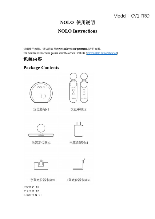
For detailed instructions,please visit the official website (/getstarted )包装内容PackageContents定位基站X1交互手柄X2头盔定位器X1Model:CV1 PROPositioning Base Station*1 Interactive Controller*2 Headset Marker*1电源适配器X1一字型定位器卡座X1L型定位器卡座X1 Power Adapter*1 Slotted Positioner Socket*1 L-type Positioner Socket*1一分三充电线X1OTG数据线X21米数据线X1一字型定位器卡座X1Three-In-One Charging Cable*1OTG Data Cable*21m Data Cable*1Slotted Positioner Socket*1了解设备Learn More about the Device交互手柄1扳机键2配对键3侧按键4触控板5菜单键6指示灯7系统/电源键Interactive Controller1Trigger Key2Pairing Key3Side Keys(Each for the left and right sides) 4Touch Key5Menu Key6Indicator Lamp7System/Power Key定位基站电源键配对键Positioning Base Station Power KeyPairing Key头盔定位器指示灯USB接口配对键Headset Marker Indicator LampUSB Interface Pairing Key一.配合VR—体机使用说明I.Instructions for Standalone Headsets1.搭建网络环境1.Set up the network environment将路由器和电脑通过网线连接;将VR—体机和电脑连接至同一路由器的5G Wi-Fi频段。
华为华三常用display命令

华为华三常用display命令
爱学习de小乌龟2019-07-22 09:25:38
华为华三通用:
dispaly cu 查看当前配置
dispaly irf 查看堆叠状态
display clock 查看系统时间,
display environment查看温度
display logbuffer查看日志信息
display device 查看单板运行状态(注:路由交换设备通常多块板子)display cpu-usage查看cpu状态
display ip interface brief 查看ip
display interface brief 查看接口状态
display version 查看设备版本
display license 查看license信息
display power 查看电源信息
display fan 查看风扇信息
dispaly ntp status 查看ntp服务器
display vlan 查看vlan
dispaly vrrp brief 查看vrrp主备信息
display device manuinfo 序列号
display ip routing 查看路由表
displayospf peer 查看ospf邻居
dis transceiver interface Ten-GigabitEthernet 查看光模块接口查看NE设备单板:
Display device
Display device pac
display elabel
•华为公司
•中央处理器。
NuMicro N9H30系列开发板用户手册说明书

NuMicro®FamilyArm® ARM926EJ-S BasedNuMaker-HMI-N9H30User ManualEvaluation Board for NuMicro® N9H30 SeriesNUMAKER-HMI-N9H30 USER MANUALThe information described in this document is the exclusive intellectual property ofNuvoton Technology Corporation and shall not be reproduced without permission from Nuvoton.Nuvoton is providing this document only for reference purposes of NuMicro microcontroller andmicroprocessor based system design. Nuvoton assumes no responsibility for errors or omissions.All data and specifications are subject to change without notice.For additional information or questions, please contact: Nuvoton Technology Corporation.Table of Contents1OVERVIEW (5)1.1Features (7)1.1.1NuMaker-N9H30 Main Board Features (7)1.1.2NuDesign-TFT-LCD7 Extension Board Features (7)1.2Supporting Resources (8)2NUMAKER-HMI-N9H30 HARDWARE CONFIGURATION (9)2.1NuMaker-N9H30 Board - Front View (9)2.2NuMaker-N9H30 Board - Rear View (14)2.3NuDesign-TFT-LCD7 - Front View (20)2.4NuDesign-TFT-LCD7 - Rear View (21)2.5NuMaker-N9H30 and NuDesign-TFT-LCD7 PCB Placement (22)3NUMAKER-N9H30 AND NUDESIGN-TFT-LCD7 SCHEMATICS (24)3.1NuMaker-N9H30 - GPIO List Circuit (24)3.2NuMaker-N9H30 - System Block Circuit (25)3.3NuMaker-N9H30 - Power Circuit (26)3.4NuMaker-N9H30 - N9H30F61IEC Circuit (27)3.5NuMaker-N9H30 - Setting, ICE, RS-232_0, Key Circuit (28)NUMAKER-HMI-N9H30 USER MANUAL3.6NuMaker-N9H30 - Memory Circuit (29)3.7NuMaker-N9H30 - I2S, I2C_0, RS-485_6 Circuit (30)3.8NuMaker-N9H30 - RS-232_2 Circuit (31)3.9NuMaker-N9H30 - LCD Circuit (32)3.10NuMaker-N9H30 - CMOS Sensor, I2C_1, CAN_0 Circuit (33)3.11NuMaker-N9H30 - RMII_0_PF Circuit (34)3.12NuMaker-N9H30 - RMII_1_PE Circuit (35)3.13NuMaker-N9H30 - USB Circuit (36)3.14NuDesign-TFT-LCD7 - TFT-LCD7 Circuit (37)4REVISION HISTORY (38)List of FiguresFigure 1-1 Front View of NuMaker-HMI-N9H30 Evaluation Board (5)Figure 1-2 Rear View of NuMaker-HMI-N9H30 Evaluation Board (6)Figure 2-1 Front View of NuMaker-N9H30 Board (9)Figure 2-2 Rear View of NuMaker-N9H30 Board (14)Figure 2-3 Front View of NuDesign-TFT-LCD7 Board (20)Figure 2-4 Rear View of NuDesign-TFT-LCD7 Board (21)Figure 2-5 Front View of NuMaker-N9H30 PCB Placement (22)Figure 2-6 Rear View of NuMaker-N9H30 PCB Placement (22)Figure 2-7 Front View of NuDesign-TFT-LCD7 PCB Placement (23)Figure 2-8 Rear View of NuDesign-TFT-LCD7 PCB Placement (23)Figure 3-1 GPIO List Circuit (24)Figure 3-2 System Block Circuit (25)Figure 3-3 Power Circuit (26)Figure 3-4 N9H30F61IEC Circuit (27)Figure 3-5 Setting, ICE, RS-232_0, Key Circuit (28)Figure 3-6 Memory Circuit (29)Figure 3-7 I2S, I2C_0, RS-486_6 Circuit (30)Figure 3-8 RS-232_2 Circuit (31)Figure 3-9 LCD Circuit (32)NUMAKER-HMI-N9H30 USER MANUAL Figure 3-10 CMOS Sensor, I2C_1, CAN_0 Circuit (33)Figure 3-11 RMII_0_PF Circuit (34)Figure 3-12 RMII_1_PE Circuit (35)Figure 3-13 USB Circuit (36)Figure 3-14 TFT-LCD7 Circuit (37)List of TablesTable 2-1 LCD Panel Combination Connector (CON8) Pin Function (11)Table 2-2 Three Sets of Indication LED Functions (12)Table 2-3 Six Sets of User SW, Key Matrix Functions (12)Table 2-4 CMOS Sensor Connector (CON10) Function (13)Table 2-5 JTAG ICE Interface (J2) Function (14)Table 2-6 Expand Port (CON7) Function (16)Table 2-7 UART0 (J3) Function (16)Table 2-8 UART2 (J6) Function (16)Table 2-9 RS-485_6 (SW6~8) Function (17)Table 2-10 Power on Setting (SW4) Function (17)Table 2-11 Power on Setting (S2) Function (17)Table 2-12 Power on Setting (S3) Function (17)Table 2-13 Power on Setting (S4) Function (17)Table 2-14 Power on Setting (S5) Function (17)Table 2-15 Power on Setting (S7/S6) Function (18)Table 2-16 Power on Setting (S9/S8) Function (18)Table 2-17 CMOS Sensor Connector (CON9) Function (19)Table 2-18 CAN_0 (SW9~10) Function (19)NUMAKER-HMI-N9H30 USER MANUAL1 OVERVIEWThe NuMaker-HMI-N9H30 is an evaluation board for GUI application development. The NuMaker-HMI-N9H30 consists of two parts: a NuMaker-N9H30 main board and a NuDesign-TFT-LCD7 extensionboard. The NuMaker-HMI-N9H30 is designed for project evaluation, prototype development andvalidation with HMI (Human Machine Interface) function.The NuMaker-HMI-N9H30 integrates touchscreen display, voice input/output, rich serial port serviceand I/O interface, providing multiple external storage methods.The NuDesign-TFT-LCD7 can be plugged into the main board via the DIN_32x2 extension connector.The NuDesign-TFT-LCD7 includes one 7” LCD which the resolution is 800x480 with RGB-24bits andembedded the 4-wires resistive type touch panel.Figure 1-1 Front View of NuMaker-HMI-N9H30 Evaluation BoardNUMAKER-HMI-N9H30 USER MANUAL Figure 1-2 Rear View of NuMaker-HMI-N9H30 Evaluation Board1.1 Features1.1.1 NuMaker-N9H30 Main Board Features●N9H30F61IEC chip: LQFP216 pin MCP package with DDR (64 MB)●SPI Flash using W25Q256JVEQ (32 MB) booting with quad mode or storage memory●NAND Flash using W29N01HVSINA (128 MB) booting or storage memory●One Micro-SD/TF card slot served either as a SD memory card for data storage or SDIO(Wi-Fi) device●Two sets of COM ports:–One DB9 RS-232 port with UART_0 used 75C3232E transceiver chip can be servedfor function debug and system development.–One DB9 RS-232 port with UART_2 used 75C3232E transceiver chip for userapplication●22 GPIO expansion ports, including seven sets of UART functions●JTAG interface provided for software development●Microphone input and Earphone/Speaker output with 24-bit stereo audio codec(NAU88C22) for I2S interfaces●Six sets of user-configurable push button keys●Three sets of LEDs for status indication●Provides SN65HVD230 transceiver chip for CAN bus communication●Provides MAX3485 transceiver chip for RS-485 device connection●One buzzer device for program applicationNUMAKER-HMI-N9H30 USER MANUAL●Two sets of RJ45 ports with Ethernet 10/100 Mbps MAC used IP101GR PHY chip●USB_0 that can be used as Device/HOST and USB_1 that can be used as HOSTsupports pen drives, keyboards, mouse and printers●Provides over-voltage and over current protection used APL3211A chip●Retain RTC battery socket for CR2032 type and ADC0 detect battery voltage●System power could be supplied by DC-5V adaptor or USB VBUS1.1.2 NuDesign-TFT-LCD7 Extension Board Features●7” resolution 800x480 4-wire resistive touch panel for 24-bits RGB888 interface●DIN_32x2 extension connector1.2 Supporting ResourcesFor sample codes and introduction about NuMaker-N9H30, please refer to N9H30 BSP:https:///products/gui-solution/gui-platform/numaker-hmi-n9h30/?group=Software&tab=2Visit NuForum for further discussion about the NuMaker-HMI-N9H30:/viewforum.php?f=31 NUMAKER-HMI-N9H30 USER MANUALNUMAKER-HMI-N9H30 USER MANUAL2 NUMAKER-HMI-N9H30 HARDWARE CONFIGURATION2.1 NuMaker-N9H30 Board - Front View Combination Connector (CON8)6 set User SWs (K1~6)3set Indication LEDs (LED1~3)Power Supply Switch (SW_POWER1)Audio Codec(U10)Microphone(M1)NAND Flash(U9)RS-232 Transceiver(U6, U12)RS-485 Transceiver(U11)CAN Transceiver (U13)Figure 2-1 Front View of NuMaker-N9H30 BoardFigure 2-1 shows the main components and connectors from the front side of NuMaker-N9H30 board. The following lists components and connectors from the front view:NuMaker-N9H30 board and NuDesign-TFT-LCD7 board combination connector (CON8). This panel connector supports 4-/5-wire resistive touch or capacitance touch panel for 24-bits RGB888 interface.Connector GPIO pin of N9H30 FunctionCON8.1 - Power 3.3VCON8.2 - Power 3.3VCON8.3 GPD7 LCD_CSCON8.4 GPH3 LCD_BLENCON8.5 GPG9 LCD_DENCON8.7 GPG7 LCD_HSYNCCON8.8 GPG6 LCD_CLKCON8.9 GPD15 LCD_D23(R7)CON8.10 GPD14 LCD_D22(R6)CON8.11 GPD13 LCD_D21(R5)CON8.12 GPD12 LCD_D20(R4)CON8.13 GPD11 LCD_D19(R3)CON8.14 GPD10 LCD_D18(R2)CON8.15 GPD9 LCD_D17(R1)CON8.16 GPD8 LCD_D16(R0)CON8.17 GPA15 LCD_D15(G7)CON8.18 GPA14 LCD_D14(G6)CON8.19 GPA13 LCD_D13(G5)CON8.20 GPA12 LCD_D12(G4)CON8.21 GPA11 LCD_D11(G3)CON8.22 GPA10 LCD_D10(G2)CON8.23 GPA9 LCD_D9(G1) NUMAKER-HMI-N9H30 USER MANUALCON8.24 GPA8 LCD_D8(G0)CON8.25 GPA7 LCD_D7(B7)CON8.26 GPA6 LCD_D6(B6)CON8.27 GPA5 LCD_D5(B5)CON8.28 GPA4 LCD_D4(B4)CON8.29 GPA3 LCD_D3(B3)CON8.30 GPA2 LCD_D2(B2)CON8.31 GPA1 LCD_D1(B1)CON8.32 GPA0 LCD_D0(B0)CON8.33 - -CON8.34 - -CON8.35 - -CON8.36 - -CON8.37 GPB2 LCD_PWMCON8.39 - VSSCON8.40 - VSSCON8.41 ADC7 XPCON8.42 ADC3 VsenCON8.43 ADC6 XMCON8.44 ADC4 YMCON8.45 - -CON8.46 ADC5 YPCON8.47 - VSSCON8.48 - VSSCON8.49 GPG0 I2C0_CCON8.50 GPG1 I2C0_DCON8.51 GPG5 TOUCH_INTCON8.52 - -CON8.53 - -CON8.54 - -CON8.55 - -NUMAKER-HMI-N9H30 USER MANUAL CON8.56 - -CON8.57 - -CON8.58 - -CON8.59 - VSSCON8.60 - VSSCON8.61 - -CON8.62 - -CON8.63 - Power 5VCON8.64 - Power 5VTable 2-1 LCD Panel Combination Connector (CON8) Pin Function●Power supply switch (SW_POWER1): System will be powered on if the SW_POWER1button is pressed●Three sets of indication LEDs:LED Color DescriptionsLED1 Red The system power will beterminated and LED1 lightingwhen the input voltage exceeds5.7V or the current exceeds 2A.LED2 Green Power normal state.LED3 Green Controlled by GPH2 pin Table 2-2 Three Sets of Indication LED Functions●Six sets of user SW, Key Matrix for user definitionKey GPIO pin of N9H30 FunctionK1 GPF10 Row0 GPB4 Col0K2 GPF10 Row0 GPB5 Col1K3 GPE15 Row1 GPB4 Col0K4 GPE15 Row1 GPB5 Col1K5 GPE14 Row2 GPB4 Col0K6GPE14 Row2GPB5 Col1 Table 2-3 Six Sets of User SW, Key Matrix Functions●NAND Flash (128 MB) with Winbond W29N01HVS1NA (U9)●Microphone (M1): Through Nuvoton NAU88C22 chip sound input●Audio CODEC chip (U10): Nuvoton NAU88C22 chip connected to N9H30 using I2Sinterface–SW6/SW7/SW8: 1-2 short for RS-485_6 function and connected to 2P terminal (CON5and J5)–SW6/SW7/SW8: 2-3 short for I2S function and connected to NAU88C22 (U10).●CMOS Sensor connector (CON10, SW9~10)–SW9~10: 1-2 short for CAN_0 function and connected to 2P terminal (CON11)–SW9~10: 2-3 short for CMOS sensor function and connected to CMOS sensorconnector (CON10)Connector GPIO pin of N9H30 FunctionCON10.1 - VSSCON10.2 - VSSNUMAKER-HMI-N9H30 USER MANUALCON10.3 - Power 3.3VCON10.4 - Power 3.3VCON10.5 - -CON10.6 - -CON10.7 GPI4 S_PCLKCON10.8 GPI3 S_CLKCON10.9 GPI8 S_D0CON10.10 GPI9 S_D1CON10.11 GPI10 S_D2CON10.12 GPI11 S_D3CON10.13 GPI12 S_D4CON10.14 GPI13 S_D5CON10.15 GPI14 S_D6CON10.16 GPI15 S_D7CON10.17 GPI6 S_VSYNCCON10.18 GPI5 S_HSYNCCON10.19 GPI0 S_PWDNNUMAKER-HMI-N9H30 USER MANUAL CON10.20 GPI7 S_nRSTCON10.21 GPG2 I2C1_CCON10.22 GPG3 I2C1_DCON10.23 - VSSCON10.24 - VSSTable 2-4 CMOS Sensor Connector (CON10) FunctionNUMAKER-HMI-N9H30 USER MANUAL2.2NuMaker-N9H30 Board - Rear View5V In (CON1)RS-232 DB9 (CON2,CON6)Expand Port (CON7)Speaker Output (J4)Earphone Output (CON4)Buzzer (BZ1)System ResetSW (SW5)SPI Flash (U7,U8)JTAG ICE (J2)Power ProtectionIC (U1)N9H30F61IEC (U5)Micro SD Slot (CON3)RJ45 (CON12, CON13)USB1 HOST (CON15)USB0 Device/Host (CON14)CAN_0 Terminal (CON11)CMOS Sensor Connector (CON9)Power On Setting(SW4, S2~S9)RS-485_6 Terminal (CON5)RTC Battery(BT1)RMII PHY (U14,U16)Figure 2-2 Rear View of NuMaker-N9H30 BoardFigure 2-2 shows the main components and connectors from the rear side of NuMaker-N9H30 board. The following lists components and connectors from the rear view:● +5V In (CON1): Power adaptor 5V input ●JTAG ICE interface (J2) ConnectorGPIO pin of N9H30Function J2.1 - Power 3.3V J2.2 GPJ4 nTRST J2.3 GPJ2 TDI J2.4 GPJ1 TMS J2.5 GPJ0 TCK J2.6 - VSS J2.7 GPJ3 TD0 J2.8-RESETTable 2-5 JTAG ICE Interface (J2) Function●SPI Flash (32 MB) with Winbond W25Q256JVEQ (U7); only one (U7 or U8) SPI Flashcan be used●System Reset (SW5): System will be reset if the SW5 button is pressed●Buzzer (BZ1): Control by GPB3 pin of N9H30●Speaker output (J4): Through the NAU88C22 chip sound output●Earphone output (CON4): Through the NAU88C22 chip sound output●Expand port for user use (CON7):Connector GPIO pin of N9H30 FunctionCON7.1 - Power 3.3VCON7.2 - Power 3.3VCON7.3 GPE12 UART3_TXDCON7.4 GPH4 UART1_TXDCON7.5 GPE13 UART3_RXDCON7.6 GPH5 UART1_RXDCON7.7 GPB0 UART5_TXDCON7.8 GPH6 UART1_RTSCON7.9 GPB1 UART5_RXDCON7.10 GPH7 UART1_CTSCON7.11 GPI1 UART7_TXDNUMAKER-HMI-N9H30 USER MANUAL CON7.12 GPH8 UART4_TXDCON7.13 GPI2 UART7_RXDCON7.14 GPH9 UART4_RXDCON7.15 - -CON7.16 GPH10 UART4_RTSCON7.17 - -CON7.18 GPH11 UART4_CTSCON7.19 - VSSCON7.20 - VSSCON7.21 GPB12 UART10_TXDCON7.22 GPH12 UART8_TXDCON7.23 GPB13 UART10_RXDCON7.24 GPH13 UART8_RXDCON7.25 GPB14 UART10_RTSCON7.26 GPH14 UART8_RTSCON7.27 GPB15 UART10_CTSCON7.28 GPH15 UART8_CTSCON7.29 - Power 5VCON7.30 - Power 5VTable 2-6 Expand Port (CON7) Function●UART0 selection (CON2, J3):–RS-232_0 function and connected to DB9 female (CON2) for debug message output.–GPE0/GPE1 connected to 2P terminal (J3).Connector GPIO pin of N9H30 Function J3.1 GPE1 UART0_RXDJ3.2 GPE0 UART0_TXDTable 2-7 UART0 (J3) Function●UART2 selection (CON6, J6):–RS-232_2 function and connected to DB9 female (CON6) for debug message output –GPF11~14 connected to 4P terminal (J6)Connector GPIO pin of N9H30 Function J6.1 GPF11 UART2_TXDJ6.2 GPF12 UART2_RXDJ6.3 GPF13 UART2_RTSJ6.4 GPF14 UART2_CTSTable 2-8 UART2 (J6) Function●RS-485_6 selection (CON5, J5, SW6~8):–SW6~8: 1-2 short for RS-485_6 function and connected to 2P terminal (CON5 and J5) –SW6~8: 2-3 short for I2S function and connected to NAU88C22 (U10)Connector GPIO pin of N9H30 FunctionSW6:1-2 shortGPG11 RS-485_6_DISW6:2-3 short I2S_DOSW7:1-2 shortGPG12 RS-485_6_ROSW7:2-3 short I2S_DISW8:1-2 shortGPG13 RS-485_6_ENBSW8:2-3 short I2S_BCLKNUMAKER-HMI-N9H30 USER MANUALTable 2-9 RS-485_6 (SW6~8) FunctionPower on setting (SW4, S2~9).SW State FunctionSW4.2/SW4.1 ON/ON Boot from USB SW4.2/SW4.1 ON/OFF Boot from eMMC SW4.2/SW4.1 OFF/ON Boot from NAND Flash SW4.2/SW4.1 OFF/OFF Boot from SPI Flash Table 2-10 Power on Setting (SW4) FunctionSW State FunctionS2 Short System clock from 12MHzcrystalS2 Open System clock from UPLL output Table 2-11 Power on Setting (S2) FunctionSW State FunctionS3 Short Watchdog Timer OFFS3 Open Watchdog Timer ON Table 2-12 Power on Setting (S3) FunctionSW State FunctionS4 Short GPJ[4:0] used as GPIO pinS4Open GPJ[4:0] used as JTAG ICEinterfaceTable 2-13 Power on Setting (S4) FunctionSW State FunctionS5 Short UART0 debug message ONS5 Open UART0 debug message OFFTable 2-14 Power on Setting (S5) FunctionSW State FunctionS7/S6 Short/Short NAND Flash page size 2KBS7/S6 Short/Open NAND Flash page size 4KBS7/S6 Open/Short NAND Flash page size 8KBNUMAKER-HMI-N9H30 USER MANUALS7/S6 Open/Open IgnoreTable 2-15 Power on Setting (S7/S6) FunctionSW State FunctionS9/S8 Short/Short NAND Flash ECC type BCH T12S9/S8 Short/Open NAND Flash ECC type BCH T15S9/S8 Open/Short NAND Flash ECC type BCH T24S9/S8 Open/Open IgnoreTable 2-16 Power on Setting (S9/S8) FunctionCMOS Sensor connector (CON9, SW9~10)–SW9~10: 1-2 short for CAN_0 function and connected to 2P terminal (CON11).–SW9~10: 2-3 short for CMOS sensor function and connected to CMOS sensorconnector (CON9).Connector GPIO pin of N9H30 FunctionCON9.1 - VSSCON9.2 - VSSCON9.3 - Power 3.3VCON9.4 - Power 3.3V NUMAKER-HMI-N9H30 USER MANUALCON9.5 - -CON9.6 - -CON9.7 GPI4 S_PCLKCON9.8 GPI3 S_CLKCON9.9 GPI8 S_D0CON9.10 GPI9 S_D1CON9.11 GPI10 S_D2CON9.12 GPI11 S_D3CON9.13 GPI12 S_D4CON9.14 GPI13 S_D5CON9.15 GPI14 S_D6CON9.16 GPI15 S_D7CON9.17 GPI6 S_VSYNCCON9.18 GPI5 S_HSYNCCON9.19 GPI0 S_PWDNCON9.20 GPI7 S_nRSTCON9.21 GPG2 I2C1_CCON9.22 GPG3 I2C1_DCON9.23 - VSSCON9.24 - VSSTable 2-17 CMOS Sensor Connector (CON9) Function●CAN_0 Selection (CON11, SW9~10):–SW9~10: 1-2 short for CAN_0 function and connected to 2P terminal (CON11) –SW9~10: 2-3 short for CMOS sensor function and connected to CMOS sensor connector (CON9, CON10)SW GPIO pin of N9H30 FunctionSW9:1-2 shortGPI3 CAN_0_RXDSW9:2-3 short S_CLKSW10:1-2 shortGPI4 CAN_0_TXDSW10:2-3 short S_PCLKTable 2-18 CAN_0 (SW9~10) Function●USB0 Device/HOST Micro-AB connector (CON14), where CON14 pin4 ID=1 is Device,ID=0 is HOST●USB1 for USB HOST with Type-A connector (CON15)●RJ45_0 connector with LED indicator (CON12), RMII PHY with IP101GR (U14)●RJ45_1 connector with LED indicator (CON13), RMII PHY with IP101GR (U16)●Micro-SD/TF card slot (CON3)●SOC CPU: Nuvoton N9H30F61IEC (U5)●Battery power for RTC 3.3V powered (BT1, J1), can detect voltage by ADC0●RTC power has 3 sources:–Share with 3.3V I/O power–Battery socket for CR2032 (BT1)–External connector (J1)●Board version 2.1NUMAKER-HMI-N9H30 USER MANUAL2.3 NuDesign-TFT-LCD7 -Front ViewFigure 2-3 Front View of NuDesign-TFT-LCD7 BoardFigure 2-3 shows the main components and connectors from the Front side of NuDesign-TFT-LCD7board.7” resolution 800x480 4-W resistive touch panel for 24-bits RGB888 interface2.4 NuDesign-TFT-LCD7 -Rear ViewFigure 2-4 Rear View of NuDesign-TFT-LCD7 BoardFigure 2-4 shows the main components and connectors from the rear side of NuDesign-TFT-LCD7board.NuMaker-N9H30 and NuDesign-TFT-LCD7 combination connector (CON1).NUMAKER-HMI-N9H30 USER MANUAL 2.5 NuMaker-N9H30 and NuDesign-TFT-LCD7 PCB PlacementFigure 2-5 Front View of NuMaker-N9H30 PCB PlacementFigure 2-6 Rear View of NuMaker-N9H30 PCB PlacementNUMAKER-HMI-N9H30 USER MANUALFigure 2-7 Front View of NuDesign-TFT-LCD7 PCB PlacementFigure 2-8 Rear View of NuDesign-TFT-LCD7 PCB Placement3 NUMAKER-N9H30 AND NUDESIGN-TFT-LCD7 SCHEMATICS3.1 NuMaker-N9H30 - GPIO List CircuitFigure 3-1 shows the N9H30F61IEC GPIO list circuit.Figure 3-1 GPIO List Circuit NUMAKER-HMI-N9H30 USER MANUAL3.2 NuMaker-N9H30 - System Block CircuitFigure 3-2 shows the System Block Circuit.NUMAKER-HMI-N9H30 USER MANUALFigure 3-2 System Block Circuit3.3 NuMaker-N9H30 - Power CircuitFigure 3-3 shows the Power Circuit.NUMAKER-HMI-N9H30 USER MANUALFigure 3-3 Power Circuit3.4 NuMaker-N9H30 - N9H30F61IEC CircuitFigure 3-4 shows the N9H30F61IEC Circuit.Figure 3-4 N9H30F61IEC CircuitNUMAKER-HMI-N9H30 USER MANUAL3.5 NuMaker-N9H30 - Setting, ICE, RS-232_0, Key CircuitFigure 3-5 shows the Setting, ICE, RS-232_0, Key Circuit.NUMAKER-HMI-N9H30 USER MANUALFigure 3-5 Setting, ICE, RS-232_0, Key Circuit3.6 NuMaker-N9H30 - Memory CircuitFigure 3-6 shows the Memory Circuit.NUMAKER-HMI-N9H30 USER MANUALFigure 3-6 Memory Circuit3.7 NuMaker-N9H30 - I2S, I2C_0, RS-485_6 CircuitFigure 3-7 shows the I2S, I2C_0, RS-486_6 Circuit.NUMAKER-HMI-N9H30 USER MANUALFigure 3-7 I2S, I2C_0, RS-486_6 Circuit3.8 NuMaker-N9H30 - RS-232_2 CircuitFigure 3-8 shows the RS-232_2 Circuit.NUMAKER-HMI-N9H30 USER MANUALFigure 3-8 RS-232_2 Circuit3.9 NuMaker-N9H30 - LCD CircuitFigure 3-9 shows the LCD Circuit.NUMAKER-HMI-N9H30 USER MANUALFigure 3-9 LCD Circuit3.10 NuMaker-N9H30 - CMOS Sensor, I2C_1, CAN_0 CircuitFigure 3-10 shows the CMOS Sensor,I2C_1, CAN_0 Circuit.NUMAKER-HMI-N9H30 USER MANUALFigure 3-10 CMOS Sensor, I2C_1, CAN_0 Circuit3.11 NuMaker-N9H30 - RMII_0_PF CircuitFigure 3-11 shows the RMII_0_RF Circuit.NUMAKER-HMI-N9H30 USER MANUALFigure 3-11 RMII_0_PF Circuit3.12 NuMaker-N9H30 - RMII_1_PE CircuitFigure 3-12 shows the RMII_1_PE Circuit.NUMAKER-HMI-N9H30 USER MANUALFigure 3-12 RMII_1_PE Circuit3.13 NuMaker-N9H30 - USB CircuitFigure 3-13 shows the USB Circuit.NUMAKER-HMI-N9H30 USER MANUALFigure 3-13 USB Circuit3.14 NuDesign-TFT-LCD7 - TFT-LCD7 CircuitFigure 3-14 shows the TFT-LCD7 Circuit.Figure 3-14 TFT-LCD7 CircuitNUMAKER-HMI-N9H30 USER MANUAL4 REVISION HISTORYDate Revision Description2022.03.24 1.00 Initial version NUMAKER-HMI-N9H30 USER MANUALNUMAKER-HMI-N9H30 USER MANUALImportant NoticeNuvoton Products are neither intended nor warranted for usage in systems or equipment, anymalfunction or failure of which may cause loss of human life, bodily injury or severe propertydamage. Such applications are deemed, “Insecure Usage”.Insecure usage includes, but is not limited to: equipment for surgical implementation, atomicenergy control instruments, airplane or spaceship instruments, the control or operation ofdynamic, brake or safety systems designed for vehicular use, traffic signal instruments, all typesof safety devices, and other applications intended to support or sustain life.All Insecure Usage shall be made at customer’s risk, and in the event that third parties lay claimsto Nuvoton as a result of customer’s Insecure Usage, custome r shall indemnify the damagesand liabilities thus incurred by Nuvoton.。
Display 调试问题点

一、Display1.lcm 相关概念1.1) MIPI接口:一共有三种接口:DBI(也做CPU或MCU接口)、DPI(也叫RGB接口)、DSI.在使用DSI接口时,目前75/77都只支持到2条data lane,加上一条clock lane.使用DPI接口时,根据LCM IC支持的情况,可以选择16bus、18bus传输RGB格式文件,在GPIO 部分分为R、G、B分别对应8个GPIO(GPIO20~46期间),客户采用DPI接口需要根据选择的bus方式进行配置,推荐RGB端口全部配置为对应的复选模式,并设置为OUT输出。
采用DBI接口,有两种模式选择,一种是选择共用DPI的bus脚+DPI控制线,另一种是共用nand data pin+CPU 控制线。
1.2) DSI接口有两种sync 模式:video mode和command mode,其中video mode是BB端一直刷数据到LCM,cmd mode是在有数据更新时刷数据到LCM GRAM中)和DSI command mode相比,video mode 是需要实时传输image data到lcm端,DSI 的refresh rate决定了lcm的refresh rate。
1.3)EDS机制:92平台LCM driver中定义了esd_check和esd_recovery的接口,但ESD线程不工作。
目前在MT6589之前平台,video mode的ESD实现有三种模式,分别是:ext TE(外部TE信号检测)、int TE(内部TE信号检测)、non cout clk不同ESD方式需要注意的方面a) int TE和ext TE的检测,都不需要实现lcm_esd_check函数,而需要实现lcm_esd_recover函数。
non cont clk则不需要实现lcm_esd_check函数和lcm_esd_recover函数,而只需要在上面params中配置为TRUE即可b) ext TE的实现,需要LCM外接TE pin到BB端,同时在inital code中配置寄存器打开TE信号的输出(一般是写0x35寄存器,具体需要和LCM IC FAE确认)1.4)HDMI/MHL:目前我司HDMI/MHL的相关code和driver都是有集成在codebase中的,要使用的话,只需要只需要在对应的ProjectConfig.mk文件中开启,并且在dct中配置好对应的引脚定义即可。
ScreenBeam Pro 无线显示接收器用户指南说明书
4DSFFO#FBN 1SP Model #: 4#8% "User ManualVer 1.0Table of ContentsGetting Started 3Introduction 3Package Contents 3System Requirements 3Installing the Receiver 5Connecting the Receiver to an HDTV 5 Setting Up for the First Time 7Connecting Via Intel WiDi App 7Connecting Via Windows 8.1+ 10Connecting Via Miracast™ 12Tips for Optimal Performance 12 Display and Control Options 13 Display Mode 13Ultra-Low Delay 14USB over Network 15ScreenBeam Pro Wireless Display ReceiverRestore to Default 15 Troubleshooting and FAQs 16Troubleshooting Issues 16Frequently Asked Questions 18Speci cations 20Notices 22Warranty 22GPL Info 22EU CE Declaration of Conformity 23Technical Support 23Getting StartedIntroductionCongratulations on your purchase of a ScreenBeam Pro Wireless Display Receiver. e Receiver lets you wirelessly transmit what’s on your compatible Intel WiDi, Windows 8.1+, or Miracast™ wireless display-capable device, and displays it on your HDTV.is user manual will take you through the procedures needed to connect, con gure, and operate the Receiver, and also describe a fewdi erent possible scenarios concerning setup locations. Package Contents•ScreenBeam Pro Wireless Display Receiver (1)•Power Adapter (1)•HDMI® Cable (1)•Product documentationSystem RequirementsReceiverTo connect the Receiver, you must have the following items:•An HDTV monitor with one free HDMI port•An available power outletScreenBeam Pro Wireless Display ReceiverCompatible Devicese Receiver connects with devices that run one of the following operating systems:•4th Gen Ultrabook with Intel WiDi 4.x•Laptop or notebook with Intel WiDi 3.5 or higher •Smartphone, tablet, or laptop running Windows 8.1 or higher •Miracast™-enabled Android deviceInstalling the Receiveris chapter explains how to connect the ScreenBeam Pro Wireless Display Receiver to an HDTV monitor. Make sure you have all the contents from the Receiver’s package available before starting.Connecting the Receiver to an HDTVTo connect the Receiver to an HDTV monitor:1.Get the Receiver, power cord, and HDMI cable from theScreenBeam Pro package.2.Plug one end of the supplied HDMI cable into the HDMI port onthe Receiver, and the other end into an available HDMI port on the HDTV.3.Plug one end of the power cord into the Receiver, and the other endinto a power outlet. When Steps 1, 2, and 3 are complete, thehardware should be connected as shown in the gure, below.Note: e power outlet and cable may appear di erent than those shown in the gure.4.Make sure the HDTV is turned on and set to display the input from the correct HDMI port (the one you plugged into during Step 2).5.Verify that the “Ready to Connect” screen appears on the HDTV . e Receiver is connected to the HDTV , and ready to be congured.ScreenBeam Pro Wireless Display ReceiverSetting Up for the First Timeis chapter explains how to connect ScreenBeam Pro Wireless Display Receiver for the rst time to the source device. ere are three source device options: Intel WiDi, Windows 8.1+, or Miracast™.Connecting Via Intel WiDi Appis section explains how to connect a device running Intel’s WiDi application to the Receiver.Note: If the device’s operating system is Windows 8.1 or higher, go to the next section in this manual (“Connecting Via Windows 8.1+”) for connection instructions.unch the Intel Wireless Display Application on the device. To nd the application, go to Windows Search on the device and search for “Intel WiDi.”2. e device scans for available receivers. Select the same receiver name as seen on the HDTV and click Connect . ( e “Connect Automatically” checkbox is optional.)3.Wait until the Receiver displays a PIN on the HDTV , and a PIN entry box on the screen of the WiDi device. Enter the PIN in the PIN entry box on the WiDi device, then click Continue.ScreenBeam Pro Wireless Display Receiver4. e HDTV displays messages to show the status of the connection process.5. A “Connection Successful” screen appears on the device’s screen, as well as on the HDTV .Adjusting the HDTV PictureIf the edges of the device screen cannot be seen on the HDTV , adjust cropping. To do this, enter the WiDi application and click Settings . Navigate to the “Picture and Sound” section, select Adjust cropping…, and adjust the HDTV picture by clicking plus (+) or minus (-).Setting Up for the First TimeWiDi Software Version SupportMake sure the device supports Intel Wireless Display (WiDi) so ware version 3.5 or higher. To nd out which version of Intel WiDi the device is running, enter the Intel WiDi application and click Help , then navigate to the “About WiDi” section. To obtain the latest Intel WiDi so ware and drivers, go to: /go/wirelessdisplayupdate .Connecting Via Windows 8.1+is section explains how to connect a device running Windows 8.1 or higher to the Receiver.1.From the Windows desktop, go to the “Charms” menu and select Devices . Y ou can also use the shortcut keys, Windows logo + K .2.From the “Charms” menu, click Project.ScreenBeam Pro Wireless Display Receiver3.From the “Project” screen, select Add a wireless display .4.Select the appropriate Receiver from the list.5.Enter the PIN as displayed on the television screen, then connect and display. Click Nextto continue.Setting Up for the First TimeScreenBeam Pro Wireless Display ReceiverConnecting Via Miracast™is section explains how to connect the Receiver to a Miracast™-enabled Android device, such as a smartphone, tablet, or game console. For best performance, the Miracast™ device should be running the latest so ware.1.On a Miracast™-enabled Android device, locate and open theWireless Display Application (check for the application under“Settings”).Note: e name of the Wireless Display Application depends on the device type and model. Refer to the device’s carrier or manufacturer user manual for more details.2. e Wireless Display Application scans for available receivers. Selectthe Receiver from the list.3.Wait for the device to associate with the Receiver. When it does, thedevice’s screen will be displayed on the HDTV.Tips for Optimal Performance•Keep the Receiver within line-of-sight of the source device. Doing this will help ensure the HDTV receives the best possible signal.• e Receiver’s optimal wireless range is within 30 feet of the source device. However, actual range and e ectiveness depends on many factors, including other sources of interference and the building materials used in the surrounding structure.Display and Control Optionsis chapter describes the various display options o ered by di erent manufacturers and operating systems that are supported by the ScreenBeam Pro Wireless Display Receiver.Display Modee Receiver supports three display modes when connected with a compatible wireless display application (Intel WiDi or Windows 8.1 Project, for example). In Windows, select Display mode by pressing the Windows logo + P keys simultaneously and selecting the appropriate mode from the “Options” menu.DuplicateDuplicate mode is used to display the same content on both the device’s screen and the HDTV simultaneously.Note: ere may be a minor delay between the display showing on the HDTV screen compared to the device screen. is is due to the current state of wireless display technology.ExtendExtend mode creates a single, extended “screen” between the source device and the HDTV. When in Extend mode, dragging windows to right side of the device’s screen displays those windows on the HDTV, while dragging windows to the le of the HDTV screen displays them back on the device’s screen. is mode allows users to display selected content on the HDTV, while all other windows remain on the device’s screen. When this mode is rst selected, the HDTV displays only the Windows desktop.ScreenBeam Pro Wireless Display ReceiverSecond Screen OnlySecond Screen Only mode causes the HDTV to be the only display for the device. In this mode, the device’s screen will be blank.Ultra-Low Delaye Receiver also supports Ultra-Low Delay mode, which helps reduce end-to-end wireless display latency. Real-time applications, such as games, can run without noticeable delay when Ultra-Low Delay mode is enabled on supported devices.Intel WiDi 4.0 and higherTo activate Ultra-Low Delay on a device running Intel WiDi 4.0or higher:unch the Intel WiDi application, then select Settings.2.From the “Settings” screen, select Current Wireless Display.3.Select Prioritize Speed from the “Quality vs. Speed” menu. Refer toIntel’s support documentation for more information.NVidia Shield1.Go to “Settings,” then select Miracast™.2.Tap on the toggle switch to turn “Game Mode” on.Note: e output resolution will reset to 720P once this mode is enabled. Refer to the device’s user manual for more information.Display and Control OptionsUSB over Networke Receiver’s USB over Network (UoIP) feature allows the use of USB HID peripheral devices, either from the source device or from the USB device side. To connect a USB keyboard, mouse, or trackpad:1.Plug the device into the Receiver’s USB port and wait for the device tobe detected. is may take 10-15 seconds.e the USB keyboard, mouse, or trackpad to control the device. Restore to DefaultTo restore the Receiver’s default factory settings:1.A er the Receiver is powered on, wait until the “Ready to Connect”screen is displayed on the HDTV.2.Hold down the Receiver’s “Reset” button.3.When the “Restore to Default” screen appears on the HDTV, releasethe “Reset” button.When the Receiver reboots, it will be running with its default settings.Troubleshooting and FAQsis chapter describes some problems you may encounter using the ScreenBeam Wireless Display Receiver, and possible solutions to those problems. Also included are frequently asked questions, and answers to those questions.Troubleshooting IssuesI'm not seeing anything on my HDTV screen after powering on the Receiver.Check the cable connections and make sure the TV Input setting is the same as the HDMI port to which the Receiver is connected.When I connect to an access point or wireless router with an active WiDi session, the WiDi connection drops.is a known issue with Intel WiDi. To solve the problem, connect the Intel WiDi PC to an access point or wireless router before starting a WiDi session.In some instances, I can’t connect to the Receiver from WiDi after installing antivirus software.is is also a known issue with Intel WiDi. To solve the problem, add Intel WiDi to the antivirus-approved whitelist of applications,then reconnect.Troubleshooting and FAQsI’m seeing artifacts and experiencing a choppy, judderingvideo stream.In noisy WiFi environments, audio and video freezes may be observed while playing video content, and longer than expected latency may occur when streaming. To ensure you have an optimal WiFi environment:•Disconnect and reconnect the Receiver.•If the source device is connected to a wireless router, change the operating channel on the router. Refer to the wireless router’s user manual for more information.I'm seeing choppiness and brief pauses while watching Internet video on my Miracast™ device.Wireless interference may cause Internet video playback to be choppy. If this occurs, try the following;•Disconnect the device from the Receiver. Make sure the Internet connection is good and that the video playing on the phone is smooth.•Clear the Y ouTube cache and try playing the video again.I'm seeing choppiness and brief pauses while watching local video on my Miracast™ device.Wireless interference may cause the video playback to be choppy. If this occurs, try the following:•Make sure you are in the same room as the Receiver.•Set the media player to use the H/W decoder, if available.•Reboot the Miracast™ device and Receiver and connect again.•Avoid moving the Miracast™ device around too much.ScreenBeam Pro Wireless Display ReceiverFrequently Asked QuestionsHow can I adjust the display to t properly to my TV screen? Launch the Intel WiDi application, then select Settings, then Picture andSound, then Adjust Cropping. Follow the onscreen instructions to adjust the picture.Where can I obtain the latest Intel WiDi application and graphic drivers for my Intel WiDi device?To obtain the latest Intel WiDi so ware and drivers, go to/go/wirelessdisplayupdateCan I connect to the WiFi router and the Receiver simultaneously with my Intel WiDi laptop?Y es. Connect the laptop to an available WiFi router rst, and then connect to the Receiver. Y ou can then view online content and beam it to the HDTV.Can I connect to the WiFi router and the Receiver simultaneously with my Miracast™ device?Some Miracast™ devices cannot connect to both WiFi router and the Receiver at the same time. Refer to the device manufacturer's or carrier's user manual for more information.What is Wi-Fi Miracast™?Wi-Fi Certi ed Miracast™ is a groundbreaking solution for seamlessly displaying video between devices, without cables or a network connection. Users can view pictures from a smartphone on a big screen television, share a laptop screen with the conference room projector in real-time, and watch live programs from a home cable box on a tablet. Miracast™ connections are formed using Wi-Fi Certi ed Wi-Fi Direct™, so access to a Wi-Fi® network is not needed–the ability to connect is inside Miracast™-certi ed devices.Troubleshooting and FAQsWhat is Wi-Fi Direct and can I connect to the Receiver usingWi-Fi Direct?Wi-Fi Direct is a peer-to-peer technology that Miracast™ connections are formed in. Even though some newer Android 4.0 and Windows 8.1 devices may pick up the Receiver in the Wi-Fi Direct devices scan list, they will not be able to connect to the Receiver. e device must support Miracast™ to connect with the Receiver.Do I need an existing wireless network to use the Receiver?No. Since the Receiver connects directly with the Intel WiDi or Miracast™-enabled device, no wireless network is needed. However, the source device needs to be connected to an Internet router or data network to view online content.What wireless signal range can I expect with the Receiver?e Receiver is designed to be used in the same room with the source device.Can I push media to the Receiver using DLNA?No. e the Receiver is not a DLNA media receiver.Does the Receiver work with the Apple iPhone, iPad, or iPod? No. e Receiver does not support Apple devices or the AirPlay protocol. For additional frequently asked questions, go to/support.Speci cationsModel NumberSBWD100ACerti cationsIntel WiDiWi-Fi Certi ed Miracast™HDMIHDCPWirelessWi-Fi 802.11 IEEE standard 5GHz/2.4GHz Wi-Fi DirectWMMAccess MethodsPINVirtual PBC pairingLED IndicatorsPowerEnvironmentalScreenBeam Pro Wireless Display ReceiverPowerExternal, 110 - 240v 2 A, 50 - 60 HzRegulatoryFCC part 15, IC, UL, CE, C-Tick, TELEC, KCC, RoHS, EAC, and SRRCEnvironmentalOperating temperature - 0º C to 40º C (32ºF to 104ºF)Storage temperature - 0ºC to 70ºC (32ºF to 158ºF)Operating humidity - 10% to 85% non-condensingStorage humidity - 5% to 90% non-condensingNote: Speci cations are subject to change without notice.NoticesWarrantyis product has a one-year Limited Hardware Warranty and 90-day free so ware updates from date of purchase.Local Lawis Limited Warranty Statement gives the customer speci c legal rights.e customer may also have other rights which vary from state to state in the United States, from province to province in Canada, and from country to country elsewhere in the world.To the extent that this Limited Warranty Statement is inconsistent with local law, this Statement shall be deemed modi ed to be consistent with such local law. Under such local law, certain disclaimers and limitations of this Warranty Statement may not apply to the customer.Go to /products/warranty.php for more information.GPL InfoFor GNU General Public License (GPL) related information, go to http:// NoticesEU CE Declaration of ConformityTo obtain the complete Declaration of Conformity form in so copy, go to the Actiontec Electronics Declarations of Conformity EU/EEA website at /support/doce symbol below is placed in accordance with the European Union Directive 2002/96 on the Waste Electrical and Electronic Equipment (the WEEE Directive). If disposed of within the European Union, this product should be treated and recycled in accordance with the laws of your jurisdiction implementing the WEEE Directive.Technical SupportGo to /support for product support, updates, and more information including:•Firmware updates•Troubleshooting•Registration•FAQsTechnical Support Phone NumberUnited States: 1-888-436-0657。
Android Auto 模型的 Display Audio 连接指南说明书

Android Auto ™Models with Display AudioConnect a compatible Android phone to the system. You can use the touchscreen to make a phone call, listen to music, and more. Visit the Android Auto website for more information.Park in a safe place before connecting your Android smartphone and launching any compatible apps.1.Connect the phone to the front (right side *1) USB port. Compatible Android phones will prompt you to download any required apps.2.Select Enable or Disable.3.Follow any prompts shown on your phone.4.The phone will be automatically paired. A tutorial will appear on the vehicle screen.5.Select a menu option.1.Maps (Navigation): View Google Maps and operate navigation. You can only use this system or the pre-installed navigation system to set a destination with routing guidance. You cannot enter destinations using the keyboard while the vehicle is moving.2.Phone: Make phone calls or listen to voicemail.3.Home (Google Now): Display useful information organized by Android Auto into simple cards that appear only when needed.4.Music: Play music from compatible apps. Select this icon to switch between music apps.5.Return to HOME screen: Displays a menu with an option to return to the vehicle system HOME screen.6.Voice: Use voice commands via Google Voice Search to operate Android Auto. You can also press and hold the Talk button on the steering wheel (see Steering Wheel Controls) to say voice commands.*1 - If equipped AUDIO AND CONNECTIVITYAUDIO AND CONNECTIVITY Depending on use, Android Auto can share certain vehicle information (e.g., vehicle location, speed, and other operating conditions) with Google and its service providers. See Google privacy policy for details regarding Google’s use and handling of data uploaded by Android Auto. Use of Android Auto is at user’s own risk, and is subject to agreement to the Android Auto terms of use, which are presented to the user when the Android Auto application is downloaded to the user’s Android phone. Android Auto vehicle integration is provided “as is,” and Honda cannot guarantee Android Auto operability or functionality now or in the future due to, among other conditions, changes in Android Auto software/Android operating system, service interruptions, or incompatibility or obsolescence of vehicle-integrated hardware or software. See dealer for details. Only use Android Auto when conditions allow you to do so safely. See your Owner’s Manual at (U.S.) or myhonda.ca (Canada) for further license and warranty terms.。
LTC2449演示电路742快速入门指南说明书

QUICK START GUIDE FOR DEMONSTRATION CIRCUIT 7428/16 CHANNEL HIGH SPEED DELTA SIGMA ADCLTC2449 DESCRIPTIONThe LTC®2449 is an 8/16 channel, high speed, 24-bit∆Σ ADC with ten selectable speed / resolution modesfrom 6.9Hz/200nVRMS to 3.5 kHz/25µVRMS. Key DCspecifications include 5ppm INL, 5µV offset, 10ppm full-scale error and 20nV/°C offset drift. In the6.9Hz/200nVRMS mode, input normal mode rejection of50Hz and 60Hz noise is better than 87dB. The accu-racy (offset, full-scale, linearity, drift) and power dis-sipation are independent of the speed selected. The LTC2449 performs autozeroing of the ADC by revers-ing the inputs through the multiplexer output / ADC input connections. This allows an external dual buffer amplifier to isolate the signal inputs from the sam-pling current of the ADC. DC742 is a member of Linear Technology‘s QuickEval™ family of demonstration boards. It is de-signed to allow easy evaluation of the LTC2449 and may be connected directly to the target application’s analog signals while using the DC590 USB Serial Controller board and supplied software to measure performance. The exposed ground planes allow proper grounding to prototype circuitry. After evaluat-ing with LTC’s software, the digital signals can be connected to the application’s processor / controller for development of the serial interface.Design files for this circuit board are available. Call the LTC factory.LTC is a trademark of Linear Technology CorporationQUICK START PROCEDUREConnect DC742 to a DC590 USB Serial Controller us-ing the supplied 14 conductor ribbon cable. Connect DC590 to host PC with a standard USB A/B cable. Run the evaluation software supplied with DC590 or downloaded from . The correct pro-gram will be loaded automatically. Click the COLLECT button to start reading the input voltage. Click the slider at the bottom of the strip-chart display to change the oversample ratio (OSR) which will in turn change the data output rate. Tools are available for logging data, changing refer-ence voltage, changing the number of points in the strip chart and histogram, and changing the numberof points averaged for the DVM display.HARDWARE SET-UPJUMPERSJP1, JP2 – Select the positive and negative supply voltages for the onboard amplifier. Supplies can be GND and Vcc or supplied externally.JP3, JP5 – Select the source for REF+ and REF-, respectively. REF+ can be 5.00 volts from the on-board LT1236 reference (default) or supplied exter-nally. REF- can be Ground (0 volts, default) or sup-plied externally.JP4 – Select source for analog COM input, either tied to ground or supplied externally to the COM turret post.JP6 – Trigger mode, either normal (default) or ex-ternally triggered.JP7 – Trigger input signal. Pin 1 is a 5-volt logic signal, pin 2 is ground. When triggered mode is selected on JP3, a rising edge starts a new conver-sion. Note that since a conversion cannot be termi-nated once started, this signal can only be used to slow down the conversion rate.CONNECTION TO DC590 SERIAL CONTROLLERJ2 is the power and digital interface connector. Connect to DC590 serial controller with supplied 14 conductor ribbon cable.ANALOG CONNECTIONSAnalog signal connections are made via the row of turret posts along the edge of the board. Also, if you are connecting the board to an existing circuit, the exposed ground planes along the edges of the board may be used to form a solid connection be-tween grounds. GND – Ground turrets are connected directly to the internal analog ground plane.PWR GND – Power ground, connected to the power return trace.VCC – This is the supply for the ADC. Do not draw any power from this point. External power may be applied to this point after disabling the switching supply on DC590. If the DC590 serial controller is being used, the voltage must be regulated 5 volts only, as the isolation circuitry will also be powered from this supply. See the DC590 quick start guide for details.REF+, REF- - These turrets are connected to the LTC2449 REF+ and REF- pins. If the onboard refer-ence is being used, the reference voltage may be monitored from this point. An external reference may be connected to these terminals if JP3 and JP5 are configured for external reference.Note: The REF+ and REF- terminals are decoupled to ground with 0.1µF and 10 µF capacitors in paral-lel. Thus any source connected to these terminals must be able to drive a capacitive load and have very low impedance at DC. Examples are series ref-erences that require an output capacitor and C-load stable op amps such as the LT1219 and LT1368. CH0 – CH15 – These are the differential inputs to the LTC2449. They may be configured either as sin-gle –ended inputs with respect to the COM pin, or adjacent pairs may be configured as differential in-puts (CH0-1, CH2-3, etc.)EXPERIMENTSINPUT NOISESolder a short wire from the CH0 to CH1. Ensure that the buffer amplifiers are in their active region of operation by either biasing the inputs to mid – sup-ply with a 10kΩ-10kΩ divider when the buffer am-plifier is powered from Vcc and ground, or tie the inputs to ground and connect an external +7.5V / -2.5V supply to the AMPV- turret (JP1 and JP2 must be set to EXT.)Set the demo software to OSR32768 (6.8 samples per second.) and check the 2X box. Noise should be approximately 0.04ppm of Vref (200nV.) Next, se-lect different oversample ratios. Measured noise for each oversample ratio should be close to values given in the LTC2449 Data Sheet.COMMON MODE REJECTIONTie the two inputs (still connected together from previous experiment) to ground through a short wire and note the indicated voltage. Tie the inputs to REF+; the difference should be less than 5 µV due to the 120 dB CMRR of the LTC2449.This experiment requires an external power supply to the buffer amplifier.If the common mode voltage is limited to GND+0.25V to Vcc-0.25V, this test may be per-formed with the amplifier supplies set to ground and Vcc.INPUT NORMAL MODE REJECTIONThe LTC2440’s SINC4 digital filter is trimmed to strongly reject both 50 and 60 Hz line noise when operated with the internal conversion clock and oversample ratio 32768 (6.8 samples per second.) To measure input normal mode rejection, connect COM to a 2.5 volt source such as an LT1790-2.5 reference or a power supply. Connect any other input (CH0 – CH15) to the same supply through a 10kΩ resistor. Apply a 10 Hz, 2V peak-to-peak sine wave to the input through a 1uF capacitor.Select OSR32768 (6.8 samples per second) and 2X mode in the demo software and start taking data. The input noise will be quite large, and the graph of output vs. time should show large variations. Next, slowly increase the frequency to 55 Hz. The noise should be almost undetectable in the graph. Note that the indicated noise in ppm may still be above that of the datasheet specification because the inputs are not connected to a DC source. Change the OSR to 16384 (13.75 samples per sec-ond;) the noise will increase substantially, as the first notch at this OSR is at 110 Hz. Increase the signal generator frequency to 110 Hz, the noise will drop again.。
amd显卡,10bit色彩设置

amd显卡,10bit⾊彩设置AMD’s 10-bit Video Output Technology IntroductionDisplay devices with a greater bit depth than the conventional 8-bits per color channel are rapidly gaining popularity in application areas such as medical imaging, professional photography, graphics design, movie production, and entertainment in general. What makes these devices attractive to a wide array of fields is their ability to represent colors with a greater fidelity than it is possible with conventional display devices. This means what we see in the real world more accurately matches what we see on the screen, ensuring that design and diagnosis errors due to monitor limitations are minimized.In order to benefit from the increased bit depth of these display devices, graphics cards used to drive them should be capable of outputting higher bit depth information as well. For example, if a display device supports 10-bits per color channel input, its capacity will not be fully exploited unless the graphics card outputs a matching bit depth. This is where AMD’s most recent series of workstation graphics cards come into play by natively supporting the emerging standard for 10-bits per color channel (or 30-bits per pixel) video output.In this paper, we first emphasize the necessity of higher bit depths for color critical tasks followed by an overview of the 10-bit monitors currently available. We then demonstrate how users can easily benefit from this technology using AMD’s graphics cards capable of 10 bit output.The Need for 10-bit DisplaysConventional display devices use 8-bits per color channel (or 24-bits per pixel) to display images and video. Although this amounts to more than 16 million colors, it still corresponds to a fraction of the colors we perceive in the real-world. This is illustrated in Figure 1, where the green triangle shows the boundaries of the sRGB1 color space on the CIE-xy chromaticity diagram. Conventional sRGB compliant 8-bits monitors can only represent the colors that lie in this triangle, while the human eye is capable of perceiving all the colors in the entire chromaticity diagram. This discrepancy is further emphasized by the fact that today’s most professional cameras and printers have a color gamut larger than that of sRGB (such as Adobe RGB2 shown by the red triangle in Figure 1), creating a bottleneck on the display side. Figure 2 demonstrates this problem where the blue areas in a photograph taken with the Adobe RGB setting of a camera cannot be accurately represented on a conventional monitor.To solve this problem, display devices can operate in a color space with a larger gamut than that of the sRGB. This can be achieved by using purer (more saturated or monochromatic) primaries to stretch the1 sRGB is a standard color space proposed by HP and Microsoft to allow for consistent color reproduction on typical monitors, printers and the Internet. It has the same primary set as the HDTV also known as ITU-R BT. 709.2 Adobe RGB is an RGB color space with a larger gamut than sRGB. It is developed by Adobe with the printing industry in mind, as there were many colors that can be printed but not displayed by a smaller gamut color space.corners of the color gamut toward the edges of the chromaticity diagram. However, when the color gamut is expanded, using only 8-bits per color channel ceases to be sufficient to display a smooth image without banding artifacts. This is illustrated in Figure 3 with a sample set of colors in both sRGB and Adobe RGB color spaces. Note that, the spacing between the color samples increases in the Adobe RGB space since it occupies a larger area. Another example is shown in Figure 4, where only 6-bits are used to cover what should normally be an 8-bit range. Similar problems will occur if 8-bits are used to cover what should normally be a 10-bit, that is, a larger range. Therefore to convey a smooth image, one needs to use additional shades of colors, hence the need for 10-bit displays.Figure 1: The 2D color gamut of the sRGB and Adobe RGB color spaces are superimposed on the CIE-xy chromaticity diagram. Note that the colors shown inside the diagram are for illustration purposes.blue areas show the out-of-gamut colors.which may lead to banding artifacts. To avoid this problem, the bit depth of the display device needs to be increased.Figure 4: This figure illustrates the banding artifacts that would occur if a smaller number of bits are used to cover a larger color range. For illustration purposes 6-bit are used to cover a subset of the 0-255 range – similar artifacts will occur if 8-bits are used to cover a larger color space such as the Adobe RGB.10-bit Display Devices10-bit displays use 10 bits to represent each of the red, green and blue color channels. In other words, each pixel is represented with 30 bits, instead of the 24 bits used in conventional displays. To this end, 10-bit displays can generate more than a billion shades of colors.In medical imaging, display devices with higher bit depths have already been in use as they allow for more accurate identification and diagnosis. Two examples of medical displays that support 10-bits are Barco Coronis 5MP Mammo and Eizo GS510. Both are grayscale displays and are commonly used in mammography applications. There exist full color 10-bit medical displays as well such as the Eizo RadiForce R31, which can be used to visualize MRI, PET, and CR scans. Higher bit depth display devices are also entering the mainstream in graphics design, professional photography, compositing, and cinema post production. Recently HP unveiled DreamColor LP2480zx, which is a 24” LED backlit LCD display capable of presenting 30-bits per pixel color information. Another 30-bit display was introduced earlier by NEC (LCD2180WG-LED), which also uses LEDs to back light the LCD panel. Both of these displays prefer LED backlighting instead of the more traditional Cold Cathode Fluorescent Lamps (CCFL), since LEDs offer a much narrower color spectrum than fluorescents, enabling more saturated primary colors. Both the HP and the NEC display are capable of accurately representing the entire Adobe RGB color gamut.AMD’s 10-bit Display SupportAMD’s most recent series of workstation graphics cards give full support to various types of 10-bit displays including all of the models mentioned above. The communication interface can currently be single link DVI, dual link DVI, and DisplayPort depending on the input/output ports configuration of the monitor and the graphics card. Through a proprietary packed pixel format, very high resolution grayscale medical displays can be natively supported through a single link DVI. Figure 5 demonstrates how the user can enable the 10-bit display support in the OpenGL driver by simply checking the relevant checkbox in the Catalyst? Control Center (CCC).Figure 5: 10-bit display feature can be enabled by checking the “Enable 10-bit pixel format support” checkbox in the Catalyst Control Center. Note that this feature is only available in workstation (ATI FireGL?) cards.Once the 10-bit pixel format support is enabled the system will request a reboot and after that any 10-bit aware OpenGL application will be displayed in 10-bits without any clamping. In the following, we demonstrate how an application programmer can easily create a 10-bit aware OpenGL application. Choosing a 10-bit Pixel FormatThe first step in creating a 10-bit OpenGL application is choosing an appropriate pixel format. Depending on the windowing library used, this can be achieved in slightly different ways. We first demonstrate the GLUT method followed by theWGL_ARB_pixel_format extension approach.GLUTTo request a 10-bit pixel format in GLUT, the user needs to specify the appropriate display string before creating an OpenGL window using:// request 10 bit colors, a depth buffer, and double bufferingglutInitDisplayString("red=10 green=10 blue=10 depth double");After this call, any OpenGL window created with glutCreateWindow() will have a 10-bit per color channel pixel format (the window does not have to be in fullscreen). This can be verified by querying the number of bits for each color channel:// verify that each color channel has 10 bitsint red_bits, green_bits, blue_bits;glGetIntegerv(GL_RED_BITS, &red_bits);glGetIntegerv(GL_GREEN_BITS, &green_bits);glGetIntegerv(GL_BLUE_BITS, &blue_bits);WGL_ARB_pixel_format ExtensionA 10-bit pixel format can also be requested using the wglChoosePixelFormatARB()function provided by theWGL_ARB_pixel_format extension as shown below:HDC device_context; // set previous to this codeint attribs[64] = {TRUE,WGL_SUPPORT_OPENGL_ARB,TRUE,WGL_DRAW_TO_WINDOW_ARB,WGL_PIXEL_TYPE_ARB, WGL_TYPE_RGBA_ARB, 10,WGL_RED_BITS_ARB,10,WGL_GREEN_BITS_ARB,10,WGL_BLUE_BITS_ARB,WGL_DEPTH_BITS_ARB, 24,WGL_DOUBLE_BUFFER_ARB, TRUE,// zero terminates the list0,};static float fattribs[64] = {// zero terminates the list0.0f,};const int format_max = 256;int formats[format_max];unsigned int format_count; wglChoosePixelFormatARB(device_context, attribs, fattribs, format_max, formats, &format_count);// "format_count" suitable formats are in "formats".if(format_count == 0) {// there were no suitable formats} else {// For this example we just use the first match.result = SetPixelFormat(device_context, formats[0], &pfd); if(result == 0) {// error can be retrieved from GetLastError()}Creating a 10-bit TextureThe previous section highlighted several methods to choose a 10-bit pixel format. It is important to note that once a 10-bit pixel format is chosen any smooth shading operation will immediately take advantage of the increased bit depth. In other words, the user does not need to explicitly provide 10-bit input data to benefit from the increased precision. This is due to the fact the internal processing of colors in the graphics card is in floating-point precision with 10-bit (or 8-bit) conversion occurring only at the output stage.However, it is also possible to explicitly create and work with 10-bit textures as will be explained in this section. 10-bit texture support is exposed to the user through a packed RGB10_A2 texture format, which contains 10 bits for each of the color channels and 2 bits for the alpha component. For convenience, we can start by defining an auxiliary union which can be used to set the values of a 10 bit texture:// Auxiliary union used to set the values of the 10 bit textureunion format2_10_10_10{struct {unsigned int red :10;unsigned int green:10;unsigned int blue :10;unsigned int alpha:2;} bits;unsigned int u32All;};Next we allocate a memory buffer which will be filled with the user data:// Allocate a buffer which will be used as the 10 bit textureint drawWidth, drawHeight;format2_10_10_10* drawData = new format2_10_10_10 [drawWidth * drawHeight];After the buffer is successfully created, it can be filled with user data coming from any 10-bit source such as a DICOM image or a RAW camera output:// Fill the buffer with values from the user. userRed, userGreen,// and userBlue are unsigned integers in the range [0,1024].format2_10_10_10 aux;for (int y = 0; y < drawHeight; ++y)for (int x = 0; x < drawWidth; ++x){aux.bits.red = userRed; // user inputaux.bits.green = userGreen; // user inputaux.bits.blue = userBlue; // user inputdrawData[x + y * drawWidth].u32All = aux.u32All;All that remains to be done is to create a 2D texture, specify the buffer we just filled in as the texture data source, and set the desired texture parameters:// Create and bind a new textureGLuint texID;glGenTextures(1, &texID);glBindTexture(GL_TEXTURE_2D, texID);// Fill the texture image from the 10 bit buffer dataglTexImage2D(GL_TEXTURE_2D, 0, GL_RGB10_A2, drawWidth, drawHeight,0, GL_RGBA, GL_UNSIGNED_INT_2_10_10_10_REV, drawData);// Set desired texture parametersglTexParameteri(GL_TEXTURE_2D, GL_TEXTURE_MIN_FILTER, GL_LINEAR);glTexParameteri(GL_TEXTURE_2D, GL_TEXTURE_MAG_FILTER, GL_LINEAR);glTexParameteri(GL_TEXTURE_2D, GL_TEXTURE_WRAP_S, GL_CLAMP_TO_EDGE);glTexParameteri(GL_TEXTURE_2D, GL_TEXTURE_WRAP_T, GL_CLAMP_TO_EDGE);glTexEnvi(GL_TEXTURE_ENV, GL_TEXTURE_ENV_MODE, GL_REPLACE);Finally, we map the texture on a screen size quad for display on the screen:// Map the texture on a screen size quad for displayglEnable(GL_TEXTURE_2D);glBegin(GL_QUADS);glTexCoord2f(0.0, 0.0);glVertex2f(0.0, 0.0);glTexCoord2f(0.0, 1.0);glVertex2f(0.0, drawHeight);glTexCoord2f(1.0, 1.0);glVertex2f(drawWidth, drawHeight);glTexCoord2f(1.0, 0.0);glVertex2f(drawWidth, 0.0);glEnd();This sample code demonstrated how to create and display a 10-bit per color channel texture with input data explicitly specified by the user. Additionally, for off-screen rendering, 10-bit textures can be attached as render targets (i.e. color attachments) to framebuffer objects.ConclusionsAs a result of the enhanced presentation quality enabled by higher bit depths, 10-bit displays are rapidly becoming norm rather than exception in application areas such as medical imaging, professional photography, graphics design, compositing, and post production. To realize their full potential, these displays demand a higher bit depth video output from the graphics cards that are used to drive them. AMD’s most recent series of workstation cards are designed to meet this demand by natively supporting 10-bits, ensuring that crucial information is never lost in any stage of the rendering and display pipeline.Further ReadingR. W. G. Hunt. The Reproduction of Colour, Sixth edition. Chichester, UK: John Wiley and Sons Ltd., 2004.C. Poynton. Digital Video and HDTV: Algorithms and Interfaces. San Francisco: Morgan KaufmannPublishers, 2003.E. Reinhard, E. A. Khan, A. O. Akyüz, and G. M. Johnson. Color Imaging: Fundamentals and Applications.Wellesley: AK Peters Ltd., 2008.G. Wyszecki and W. S. Stiles. Color Science: Concepts and Methods, Quantitative Data and Formulae,Second edition. John Wiley and Sons Ltd., 2000.DisclaimerThe information presented in this document is for informational purposes only and may contain technical inaccuracies, omissions and typographical errors.AMD MAKES NO REPRESENTATIONS OR WARRANTIES WITH RESPECT TO THE CONTENTS HEREOF AND ASSUMES NO RESPONSIBILITY FOR ANY INACCURACIES, ERRORS OR OMISSIONS THAT MAY APPEAR IN THIS INFORMATION.AMD SPECIFICALLY DISCLAIMS ANY IMPLIED WARRANTIES OF MERCHANTABILITY OR FITNESS FOR ANY PARTICULAR PURPOSE. IN NO EVENT WILL AMD BE LIABLE TO ANY PERSON FOR ANY DIRECT, INDIRECT, SPECIAL OR OTHER CONSEQUENTIAL DAMAGES ARISING FROM THE USE OF ANY INFORMATION CONTAINED HEREIN, EVEN IF AMD IS EXPRESSLY ADVISED OF THE POSSIBILITY OF SUCH DAMAGES.2008 Advanced Micro Devices, Inc. All rights reserved. AMD, the AMD Arrow logo, ATI, the ATI logo, FireGL, FireMV, FirePro and combinations thereof are trademarks of Advanced Micro Devices, Inc. Other names are for informational purposes only and may be trademarks of their respective owners.。
- 1、下载文档前请自行甄别文档内容的完整性,平台不提供额外的编辑、内容补充、找答案等附加服务。
- 2、"仅部分预览"的文档,不可在线预览部分如存在完整性等问题,可反馈申请退款(可完整预览的文档不适用该条件!)。
- 3、如文档侵犯您的权益,请联系客服反馈,我们会尽快为您处理(人工客服工作时间:9:00-18:30)。
Display Device & Application
Chapter 2
Introduction to LCD
ITO= Indium Tin Oxide = transparent electrode
Transmittive
Often to use with backlight
►Perfect Crystal: all atoms are fixed in regular pattern. It only exist in solids
►Liquid crystal is used only between T
►Practically, the operation temperature is
Crystal
Which Phase of Liquid crstyal used in LCD ?
►TN LCD : Twisted Nematic LCD
►STN LCD: Super Twisted Nemtic LCD
►ALL are nematic
Application of Cholesteric
►Cholesteric:
► A cholesteric liquid crystal is a type of liquid crystal with a helical structure and which is therefore chiral. Cholesteric liquid crystals are also known as chiral nematic liquid crystals. They organise in layers with no positional ordering within layers, but a director axis w hich
varies with layers. The variation of the director axis tends to be
periodic in nature. The period of this variation (the distance o ver which
a full rotation of 360°is completed) is known as the pitch, p. The pitch
is varying with temperature and it can also be affected by the
boundary conditions when the chiral nematic liquid crystal is
sandwiched between two substrate planes.
►Application of Cholesteric: Epaper
Source: /wiki/Cholesteric_liquid_crystal
Temperature Effect on LC TN
20℃
TN
50℃
The upper limit is affected by the clearing point (Tc):TN: 10 °C lower than Tc STN: 30 °C lower than Tc Over the limit will have SERIOUS background color change
70℃80℃
90℃
Polarization?
► Light
is kind of electromagnetic wave and have Ex and Ey component. ► Polarizer: only allow the component of light that along its polarization axis to pass through. ► (Eycosθ=Ey, θ=00), ExCos θ=00 as θ=900, where θ is the angle between Ex or Ey and Polarizer axis
Ey
Polarizer Axis
Ey
Ex Ex is blocked due to 90 degree shift from the Polarizer axis
E&I 4270 Display Devices and Application Chapter 2 11
Polarizer Arrangement
Orthogonal (900 cross) Polarizer Axis
Parallel
E&I 4270 Display Devices and Application Chapter 2
12
How Liquid Crystal help?
Orthogonal (900 cross)
Postive Mode
V=0
Bright State
Dark State
V>> Vth
E&I 4270 Display Devices and Application Chapter 2 13
Polarizer : Parallel
Negative Mode (+Ve)
Dark State
V=0
V>> Vth
E&I 4270 Display Devices and Application Chapter 2
Bright State
14
TN-Cell (90° twist, parallel Pol.)
V=0
V>>Vth
Polarized light is turned by twisted LC-molecule helix and stopped by the 2nd polarizer
Polarized light is NOT twisted by vertical LC-molecules and can pass the 2nd polarizer
E&I 4270 Display Devices and Application Chapter 2
15
Summary of Polarizer arrangement
Font and Back Polarizer arrangement Normal Mode
Parallel
Cross (Orthogonal)
Dark Negative Mode
Bright Positive mode
E&I 4270 Display Devices and Application Chapter 2
16
。