MSP430控制段式液晶
用MSP430驱动1621芯片的段码液晶

51. //dat=k&0x80;
52. if(k&0x80) //p6.3
53. P6OUT|=0x08;
54. else
55. P6OUT&=0xf7;
56. delay(20);
57. P6OUT|=0x10; //wr=1;
156. {
157. write_dat(0,oxff); //k9,k10,k11,k12
158. display(1,0xff); //第一位 k8, c,b,a,d,e,g,f
159.160. }
7. [清风单片机]网站独家发布,如需转载或用于商业用途,请
8. 联系作者和注明网站的出处
9.10. ----------------------------------------------------
11. cs-----p65
12. wr-----p64
113. write_dat(i,0);
114. }
115./*-------------------------功能:初始化液晶-------------------*/
116.void int1621(void)
117.{
118. P6OUT|=0x20;// cs=1;
100. add=add<<2;
101. write_byte(0xa0,3); //写101
102. write_byte(add,6);
103. write_byte1(mdata,4);
104. //dely(2);
105. P6OUT|=0x20;// cs=1;
MSP430单片机驱动12864液晶程序

MSP430单片机驱动12864液晶程序#include <msp430g2553.h>typedef unsigned char uchar;typedef unsigned int uint;#define LCD_PORT_DIR P2DIR //定义P2口#define LCD_PORT_OUT P2OUT#define CS BIT0#define SID BIT1#define SCLK BIT2#define LCD_OUT LCD_PORT_DIR |= CS + SID + SCLK //定义P2.0~2.2为输出#define CS_H LCD_PORT_OUT |= CS#define CS_L LCD_PORT_OUT &= ~CS#define SID_H LCD_PORT_OUT |= SID#define SID_L LCD_PORT_OUT &= ~SID#define SCLK_H LCD_PORT_OUT |= SCLK#define SCLK_L LCD_PORT_OUT &= ~SCLKvoid Delay_1ms(void);void Delay_Nms(uint n);void Write_1byte(uint RW,uint RS,uchar data);void Write_8bits(uchar bit);void Write_Cmd(uchar cmd);void Write_Dat(uchar dat);void Write_Datas(uchar *s);void Disp_Img(uchar *img);void Lcd_Init(void);void Locat_XY(uint x,uint y);void Write_Str(uint x,uint y,uchar *s);void Write_Str1(uint x,uint y, uchar q);//unsigned int SZ_bl[]={48,49,50,51,52,53,54,55,56,57};/*******************************************函数名称:Delay_1ms功能:延时约1ms的时间参数:无返回值:无********************************************/ void Delay_1ms(void){uchar i;for(i = 150;i > 0;i--);}/*******************************************函数名称:Delay_Nms功能:延时约N个1ms的时间参数:n--延时长度返回值:无********************************************/ void Delay_Nms(uint n){uint i;for(i = n;i > 0;i--) Delay_1ms();}/*******************************************函数名称:Write_1byte功能:向LCD写1byte数据参数:RW--读写控制,RS--数据命令控制data--数据RW:0为写,1为读RS:0为命令,1为数据返回值:无********************************************/ void Write_1byte(uint RW,uint RS,uchar data){uchar H_data,L_data,ID = 0xf8;if(RW == 1) ID = ID + 0x04;if(RS == 1) ID = ID + 0x02;H_data = data;H_data &= 0xf0;L_data = data;L_data &= 0x0f;L_data <<= 4;Write_8bits(ID);Delay_1ms();Write_8bits(H_data);Delay_1ms();Write_8bits(L_data);Delay_1ms();}/*******************************************函数名称:Write_8bits功能:向LCD连续写8bits数据参数:bit--数据返回值:无********************************************/ void Write_8bits(uchar bit){uint i;for(i=0;i<8;i++){if(bit & 0x80) SID_H;else SID_L;SCLK_H;bit <<= 1;SCLK_L;}}/*******************************************函数名称:Write_Cmd功能:向LCD写控制命令参数:cmd--控制命令返回值:无********************************************/ void Write_Cmd(uchar cmd){CS_L;_NOP();CS_H;_NOP();Write_1byte(0,0,cmd);Delay_1ms();CS_L;}/*******************************************函数名称:Write_Dat功能:向LCD写显示数据参数:dat--显示数据返回值:无********************************************/void Write_Dat(uchar dat){CS_L;_NOP();CS_H;_NOP();Write_1byte(0,1,dat);Delay_1ms();CS_L;_NOP();}/*******************************************函数名称:Lcd_Init功能:液晶初始化参数:无返回值:无********************************************/void Lcd_Init(void){Delay_Nms(500);Write_Cmd(0x30); //基本指令集Delay_1ms();Write_Cmd(0x02); //地址归位Delay_1ms();Write_Cmd(0x0c); //整体显示打开,游标关闭Delay_1ms();Write_Cmd(0x01); //清除显示Delay_1ms();Write_Cmd(0x06); //游标右移Delay_1ms();Delay_1ms();}/*******************************************函数名称:Locat_XY功能:设置液晶显示地址参数:x--行地址,y--列地址0<=x<=3,0<=y<=7返回值:无********************************************/ void Locat_XY(uint x,uint y){switch(y){case 0:Write_Cmd(0x80+x);break;case 1:Write_Cmd(0x90+x);break;case 2:Write_Cmd(0x88+x);break;case 3:Write_Cmd(0x98+x);break;default:break;}}/*******************************************函数名称:Write_Datas功能:写字符串数据参数:*s--字符串数组返回值:无********************************************/ void Write_Datas(uchar *s){char i;while(*s>0){Write_Dat(*s);s++;for(i=10;i>0;i--);}}/*******************************************函数名称:Write_Str功能:向指定起始坐标写字符串参数:x--行地址,y--列地址,*s--字符串数组0<=x<=3,0<=y<=7返回值:无********************************************/void Write_Str(uint x,uint y, uchar *s){Locat_XY(x,y);Write_Datas(s);}/*******************************************函数名称:Write_Str1功能:向指定起始坐标写变量参数:x--行地址,y--列地址,q--字符串数组ASCll码值0<=x<=3,0<=y<=7返回值:无********************************************/void Write_Str1(uint x,uint y, uchar q){Locat_XY(x,y);Write_Dat(q);}/*******************************************函数名称:Disp-Img功能:显示图片参数:*img--图片数组返回值:无********************************************/void Disp_Img(uchar *img){uint j=0;uchar x,y;for(y=0;y<32;y++) //垂直坐标32位for(x=0;x<8;x++) //水平坐标16字{Write_Cmd(0x36); //开启扩展指令集Write_Cmd(y+0x80); //先写入垂直坐标Write_Cmd(x+0x80); //再写入水平坐标Write_Cmd(0x30); //基本指令集Write_Dat(img[j++]);Write_Dat(img[j++]);}for(y=0;y<32;y++) //垂直坐标32位for(x=0;x<8;x++) //水平坐标16字{Write_Cmd(0x36); //开启扩展指令集Write_Cmd(y+0x80); //先写入垂直坐标Write_Cmd(x+0x88); //在写入水平坐标Write_Cmd(0x30); //基本指令集Write_Dat(img[j++]);Write_Dat(img[j++]);}}。
MSP430基于的段显LCD驱动电路设计说明书
6th International Conference on Sensor Network and Computer Engineering (ICSNCE 2016)Design of LCD Electric Circuit Segments Basic on MSP430Jian HuangXijing University, Xi'an 710123, ChinaKeywords: Segments LCD; MSP430; Display memory; 4-MUXAbstract. Display device is very important equipment in the instrument. LED display have limited in complex driving circuit, high dissipation, big size. In order to resolve this problem, a segments LCD drive circuit is introduced, which based on ultra-low-power MSP430, using the built-in LCD controller, can drive the 160 segment LCD. The segments LCD’s type is EDS826, it has 6 bits 8 segments LCD, display principle and 4-MUX driving methods of segments LCD is given in detail. It has design drive circuit and give software flow chart. The test results show that the device can clearly display letters and numbers, have low power dissipation, simplifies design of drive circuit, can be used in the instrument to display temperature, humidity and pressure message. IntroductionCode of LCD, or a liquid crystal screen, generally called pattern type LCD screen, each segment of the electrode includes 7 segments and a back electrode BP (or COM), you can display numbers and simple characters, digit and character corresponding to its corresponding [1-3]. Compared with the digital tube segment code, the price is basically the same, the performance and the driving principle is quite different. Compare to LED, it’s display more clear, more realistic and has lower power consumption, the contents of the display will be more abundant. So it is often used as a display unit in the instrument and meter. Produced by TI company ultra low power MSP430 microcontroller, the built-in code segment LCD driver, is the best driver code segment LCD control unit, this paper focus on the principle and method for driving code segment LCD, and accordingly gives the hardware circuit design and software driver display program.Segment Code LCD Display Principle and Its MSP430 Liquid Crystal Driving MethodLiquid crystal display often has many parameters, but the driving parameters related to the only two: one is "bias", refers to the liquid crystal display / does not show and display the signal amplitude ratio; another is duty cycle that is ratio of each segment LCD display time and display cycle [2]. MSP430F4619 has its own segment LCD driver module, including four kinds of driving module, that is static type, 2-MUX type, 3-MUX type and 4-MUX type. MSP430F4619 by setting different COM to achieve the choice of driving mode, because designers often want to use the least pin to drive the LCD segment, and therefore more use of 4-MUX drive mode.Among 4-MUX LCD driver mode, every four stroke in parallel with one common pin. As shown in Fig. 1, a, b, c, h share a root tube feet, d, e, f, g sharing another single pin, driving every digital only need 2 root segment drive pin (Fig. 1 driven by S0 and S1, number 2, driven by the S2 and S3.). 4-MUX LCD has 4 common COM3 to COM0 respectively, and the MCU connected to COM3 to COM0. In addition to V1 and V5, the 4-MUX mode driver waveform requires two intermediate voltage V2 and V4, generally by three equivalent value resistance R1, R2, R3 series making voltage divider.Figure 1. 4-MUX LCD defineDrive Circuit DesignThe driving hardware circuit mainly includes MSP430 and its peripheral circuit and liquid crystal EDS826 module. The EDS826 can display 6 digits, so MSP430 only need to select S0 ~ S11 pins. We can use the button to adjust the display contents of the LCD liquid crystal.MSP430 Introduce. The main control unit is MSP430 single chip microcomputer, because the 430 single chip microprocessor is a high performance single chip microcomputer, its power consumption is low, the interface is rich, especially suitable for the main control unit in the instrument. Because MSP430 microcontroller internal LCD controller can automatically produce all the timing of LCD through the hardware, we only need to operate the LCD control register to select the LCD driver mode [4-6]. In software design, we need to write the display buffer, it can directly control the LCD light off or light on.LCD Module EDS826. LCD module uses EDS826, it can display six digits one time, each figure and its corresponding segment code shown in Fig. 2, the LCD module using 4-MUX drive [7-8]. In the design of the hardware circuit, the actual connection diagram is shown in Fig. 3. EDS826 COM0~ COM3 connected to MSP430 COM0 ~ COM3, all other pins are connected in sequence to S0 ~ S11, according to 4-MUX driving principle, S0 and S1 driving the first tube, S2 and S3 driving the second tube, by analogy, S10, S11 drive the sixth tube. The relationship between the memory and the segment code referring to the front of this paper [7].Figure 2. EDS826 pinsFigure 3. EDS826 connected to MCUSoftware ProgramSoftware Flow Chart. Software flow chart as shown in Fig. 4, first initialization LCD, then according to the above macro definition to display 0 to 5, finally we can change the display numbers through the button.Figure 4. Software flow chartPart Code. Code below can display number 0 to 5. Compiler development environment is IAR5.0.LCDACTL = LCDON+LCD4MUX+LCDFREQ_128; // 4mux LCD,LCDAPCTL0 =LCDS0+LCDS4+LCDS8; //Segments 0-11for (i=1;i<7;i++){LCDMEM[i] = char_gen[i];}Test ResultsAccording to the above description,we design the hardware circuit and software program[9], display the results as shown in Fig. 5 and Table 1Figure 5. Display resultTable 1 The code of number 0~9ConclusionThis paper describes the principle and method of the segment code LCD in detail, using MSP430F4619 to drive the segment code LCD screen EDS826, drawing the schematic and the PCB board, using c language to program the code. Experimental results show that the digital 0 to 9 can be display clearly. According to the driving method [10], the LCD can be driven more segments, and can be used to display important information in the instrument and meter equipment. References[1]Lin Fanqiang, Ma Xiaoming. Design of the segment type LCD driver, liquid crystal anddisplay [J].2012,27 (4): 523-528[2]Li Yujie. The design of the logistics safety data recorder based on MSP430 MCU [J] displaydesign.2013,32, logistics technology LCD (4): 100-102[3]Ge Huamin, Zheng Jing, Yang Liqing. Design of LCD display module based on ARM-Linux[J], instrument technology and sensor.2009,7:75-77[4]Su peace, Chi Ke. A design method for direct driven character type [J] LCD, instrumenttechnology and sensor.2004,2:35-37[5]Xie Zhao, Zhao Jian.MSP430 Series MCU system engineering design and practice [M].Machinery Industry Press, 2009[6]Texas Instruments.MSP430x4xx Family [6] s User Guide [M]. January 2010[7]EDS826 sheet. DALIAN data GOOD DISPLAY CO. LTD,, 2012[8]Tang Sichao. Embedded system software design based on Embedded Workbench [M]. IARBeijing: Beihang University press, 2010[9]Zhang Yongbin, Hu Jingao. Control and design of LCD display based on [J]. DSP LCD anddisplay.2011, 26 (5): 626-630.[10]Wang Xinxin, Xu Jiangwei, et al. Research on TFT-LCD defect detection system [J]. Journalof electronic measurement and instrument.2014, 28 (3): 278-284.[11]Y.G. Sun, W.L. Li, D.S. Dong, X. Mei, H.Y. Qiang, “Dynamics Analysis and Active Control ofa Floating Crane”, Tehnicki Vjesnik-Technical Gazette, vol.22, no. 6, pp. 1383-1391, 2015.。
msp430TFT-LCD,UART,I2C实验报告
SPI_SLAVE_Trigger(); SPI_Delay(20000); }
void main(void)
{
volatile unsigned int i;
WDTCTL = WDTPW+WDTHOLD;
// Stop watchdog timer
SPI_GPIO_Init();
// 配置SPI接口
Msp430 单片机第五次实验报告
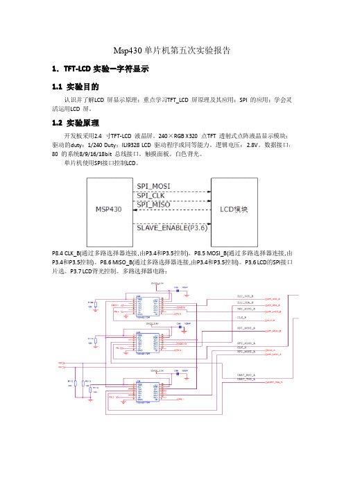
1.TFT-LCD 实验—字符显示 1.1 实验目的
认识并了解LCD 屏显示原理;重点学习TFT_LCD 屏原理及其应用;SPI 的应用;学会灵 活运用LCD 屏。
1.2 实验原理
开发板采用2.4 寸TFT-LCD 液晶屏。240×RGB X320 点TFT 透射式点阵液晶显示模块; 驱动的duty:1/240 Duty;ILI9328 LCD 驱动程序或同等能力。逻辑电压:2.8V。数据接口: 80 的系统8/9/16/18bit 总线接口。触摸面板。白色背光。
// Clock polarity high, MSB
UCB1CTL1 |= UCSSEL_2;
// SMCLK
UCB1BR0 = 0x02;
// /2
UCB1BR1 = 0;
//
//UCB1MCTL = 0;
// No modulation
UCB1CTL1 &= ~UCSWRST;
// **Initialize USCI state
17位或8位数据位支持奇偶校验2独立的发送和接收移位寄存器3独立的发送和接收缓存4可选择先发送接收msb还是lsb5空闲位多机模式和地址位多机模式6通过有效的起始位检测将msp430从低功耗唤醒7状态标志检测错误或者地址位8独立的接收和发送中断9可编程实现波特率的调整333实验步骤1将pc和板载仿真器通过usb线相连
段式液晶显示方法

MSP430F413单片机段式LCD设计中遇到的晶振、LCD驱动等问题2011-08-11 17:40这次设计所用到的微控制器为德州仪器(TI)的16位单片机 MSP430F413。
单从价格上面来说,这个是单片机也算是TI里面的最便宜的可以直接驱动段式96段 LCD 的单片机了,当时设计之初也是奔着价位而来的,由于在工作中用到过MSP430单片机做过低功耗类的产品,所以对单片机的外围以及硬件结构还是略知一二的。
相对于stc单片机的开发工具来说 430的开发工具也只是个JTAG接口,但是这个接口的价格嘛也得60元左右,由于以前做过MSP430的项目,所以开发工具是现成的!好了,言归正传,这次所用的LCD是淘宝上买的,详细资料如图所示:是个四位的 lcd,以前确实没有接触过段式LCD ,数码管倒是接触的不少,所以自己由好奇心的趋势,自己就做了一块开发板,想试试LCD的感觉。
首先开发板打样回来之后,元器件焊好,随便写了个定时器的程序进去,发现程序在10秒钟之内是运行正常的(此时还没有安装LCD,只是个指示灯在跑),不过也有偶尔程序不运行的情况,后来自己就找原因;1、mcu焊接不好?2、复位电路焊接不好?3、晶振焊接不好?逐一排查,发现前两项是很正常的,虽然PQFP的封装还是焊接的不多,但是自己的焊功还是过的去的,于是就找晶振的问题。
但是如果是晶振自身的问题的话,可能就不起振或者起振频率不对,以至于系统根本就无法定时启动。
所以疑点越来越在晶振上面,后来发现晶振自身是没有问题的,主要是原因是因为晶振的管脚焊接位置距离单片机的 XIN XOUT 管脚的距离着实有点远,大概20mm的样子,加上线走的比较细0.26mm,所以晶振启动异常,或者有时候根本不起振。
问题处在第3了。
没有办法只好用刻刀将晶振的线从单片机管脚出来大概3mm的地方划断,剥去丝印层,露出黄铜线,将晶振管脚直接焊接在黄铜线上,然后用硅胶枪将晶振和单片机封好,就是下面的样子(很丑但是很温柔)!凑合着先用一下,等实验好了的话,如果有需要就重新打样了。
基于MSP430单片机的液晶LCD048应用程序

基于MSP430单片机的液晶LCD048应用程序TI公司系列是一种超低功耗的混合信号控制器,其中包括一系列器件,它们针对不用的应用由不同的模块组成。
其中FLASH系列使高效系统变得轻便,FLASH存储器也具有很强的灵便性。
同时为了在低频率的驱动下得到较高的稳定频率,某些MSP430器件上用法了锁频技术FLL或增加型锁频环技术FLL+。
如MSP430F425的时钟模块中用法了FLL+技术,这样可以得到稳定的频率。
液晶驱动MSP430器件上的液晶的控制/驱动将简化液晶显示器的显示。
不同型号的液晶驱动能力不同,我们采纳 MSP430的F42X系列,有128段驱动能力。
液晶的驱动有4种办法:静态,2MUX或1/2占空比,3MUX或1/3占空比, 4MUX或1/4占空比。
对于不同系列、不同型号的液晶驱动原理,控制办法都是一样的,不同点在于驱动液晶段数不一样,或可显示信息的多少不一样。
我们采纳4MUX,这种方式也最容易。
其中需要注重以下两点:(1)液晶的偏压。
因为液晶驱动用法沟通,所以必需按照液晶的工作模MSP430举行偏压设置,详细的操作是:STATIC模式下,R33开路,R03-R23接地,2MUX模式下,分离在R33、R13以及R13、R03之间接上 10K的;3/4MUX模式下,分离在R33、R23之间,R23、R13以及R13、R03之间接上10K的电阻,这样就能保证COM0-COM3 出来供应液晶块的电压符合要求。
(2)频率的设置。
MSP430有三种时钟ACLK(辅助时钟)、MCLK(主时钟)、SMCLK(子时钟),其中液晶的驱动频率FCLK来自ACLK。
在XTIN和XTOUT之间接上振荡频率为32KHz的晶振,Fclk可以按照需要选为1024Hz、512Hz、256Hz、128Hz等。
由FRFQ0和FRFQ1的设置可以满足不同液晶对频率的要求,其中Flcd=2*MUX(rate)*F(framing)。
MSP430单片机与液晶显示器的串行接口方案设计(一)

MSP430单片机与液晶显示器的串行接口方案设计(一) 1概述点阵式液晶与外部的硬件接口简单,能以点阵或图形方式显示出各种信息,因此在电子设计中得到广泛应用。
但是,对它的接口设计必须遵循一定的硬件和时序规范,不同的液晶显示驱动器,可能需要采用不同的接口方式和控制指令才能够实现所需信息的显示。
某些液晶显示驱动器与外部的接口必须采用串行方式,而其串行接口往往不是标准的串行接口,这就为这类液晶显示驱动器的设计带来了困难。
针对上述问题,本文提出一种利用微控制器(MCU)的I/O端口,通过软件设计模拟与所使用的液晶显示驱动器规范相符的串行总线的设计思想,实现MCU对液晶显示驱动器的控制,从而建立起一套不但可以显示各种字符,而且可以动态显示曲线的游人显示系统。
2系统设计本文所建立的液晶显示系统,选用美国德州仪器(TI)公司的MSP430F149微控制器来控制液晶显示驱动器uPD16682A,从而实现各种信息的显示。
2.1MSP430F14X微控制器简介TI公司的MSP430F14X微控制器与其它MSP430系列微控制器相同,均甚至一个真正的正交16位RISCCPU内核:具有16个可单周期全寻址的16位寄存器,仅27条的精简指令集以及7种均采用双重取数据技术(DDFT)的一致性寻址方式。
DDFT技术利用每个时钟脉冲对存储器进行两次数据存取操作。
从而不再需要复杂的时钟乘法和指令流水线方案。
MSP430F14X系列MCU片内不但包括60多KB的Flash、2KB的RAM、一个看门狗时钟、12位16通道的A/D转换器、定时器、高精度比较器、PWM以及高速的USART控制器等常用资源,还在某些型号中集成了LCD控制器。
其I/O资源丰富,且每个输入/输出(I/O)引脚上都提供了矢量中断功能,每个外围器件都支持复杂的事件驱动型操作。
同其它微控制器相,带片内Flash的微控制器可将系统功耗降低5倍,并且减小了硬件线路板空间,与现代程序设计技术(如计算分支以及高级语言(如C语言)结合使用,使得MSP430的体系结构更为高效。
第5讲MSP430单片机LCD与TFT

本节提要
• LCD液晶显示器简介 • MSP430 LCD控制器
液晶显示器原理
在单片机的应用中,人机界面占据相当重要的地位。人 机界面主要包括事件输入和结果指示,事件输入包括键盘输 入,通讯接口,事件中断等,结果指示包括LED/LCD显示、 通讯接口、外围设备操作等。而在这些人机界面当中,LCD 显示技术由于其具有界面友好,成本较低等特点而在很多应 用场合得以广泛应用。
4-mux方式
4MUX方式有4个公共极, 所以可以用显示缓存器的位4 、5、6、7和位0、1、2、3 来存储段信息。每个字的全 部8段被安排在同一个显存字 节中。4MUX方式是最简单、 方便的显示方式。根据图459所示的连接情况和显存结 构,在4MUX方式下显示数字 “0”,可将1个显存字节内 容设置为:0XEB即显示a、b 、c、d、e、f段。
LCD寄存器
LCD的寄存器主要包括三大类: 控制寄存器(共10个) 显示缓冲寄存器
LCDM1~LCDM28 闪烁缓冲寄存器
LCDBM1~LCDBM28
LCD控制寄存器0(LCDBCTL0) LCDDIVx:第11~15位,LCD频率选择。 LCDPREx:第8~10位,LCD频率选择。 LCDSSEL:第7位,LCD刷新频率和闪烁频率时钟源选择位 0:ACLK; 1:VLOCLK; LCDMXx:第3~5位,LCD的驱动模式控制位。 000:静态驱动; 001:2MUX驱动; 010:3MUX驱动; 011:4MUX驱动;100:5MUX驱动; 101:6MUX驱动; 110:7MUX驱动;111:8MUX驱动; LCDSON:第2位,LCD所有段熄灭控制位。 0:所有LED段熄灭; 1:所有LED段使能,根据相应显示缓存点亮或熄灭。 LCDLP:第1位,LCD低功耗波形驱动使能控制位。 0:标准LCD驱动波形; 1:低功耗LCD驱动波形。 LCDON:第0位,LCD开关控制位。 0:LCD关闭; 1:LCD打开。
- 1、下载文档前请自行甄别文档内容的完整性,平台不提供额外的编辑、内容补充、找答案等附加服务。
- 2、"仅部分预览"的文档,不可在线预览部分如存在完整性等问题,可反馈申请退款(可完整预览的文档不适用该条件!)。
- 3、如文档侵犯您的权益,请联系客服反馈,我们会尽快为您处理(人工客服工作时间:9:00-18:30)。
MSP430控制段式液晶
2009-07-11 21:05:44| 分类:单片机| 标签:|字号大中小订阅
//******************************************************************************
// MSP-FET430P430 Demo - LCD, Display "0123456" on SBLCDA4 LCD
//
// Description: Displays "0123456" on SBLCDA4 LCD as used on 430 Day Watch
// board.
// ACLK = LFXT1 = 32768Hz, MCLK = SMCLK = default DCO = 32 x ACLK = 1048576Hz // //* An external watch crystal between XIN & XOUT is required for ACLK *//
//
// MSP430FG439
// -----------------
// /|\| XIN|-
// | | | 32kHz
// --|RST XOUT|-
// | | SBLCDA4
// | | (As used on 430 Day Watch Demo board)
// +-|R33 S0 | -----------------
// 1m | - |--> | + 7 6 5 4 3 2 1 |
// +-|R23 S21 | -----------------
// 1m | COM0|-----||||
// +-|R13 COM1|------|||
// 1m | COM2|-------||
// +-|R03 COM3|--------|
// | | |
// Vss
//
// L. Westlund
// Texas Instruments Inc.
// Feb 2005
// Built with CCE Version: 3.2.0 and IAR Embedded Workbench Version: 3.21A //******************************************************************************
#include <msp430xG43x.h>
// LCD segment definitions.
#define d 0x80
#define c 0x01
#define b 0x20
#define a 0x10
#define h 0x08
#define g 0x40
#define f 0x02
#define e 0x04
const char char_gen[] = { // As used in 430 Day Watch Demo board
a+b+c+d+e+f, // Displays "0"
b+c, // Displays "1"
a+b+d+e+g, // Displays "2"
a+b+c+d+g, // Displays "3"
b+c+f+g, // Displays "4"
a+c+d+f+g, // Displays "5"
a+c+d+e+f+g, // Displays "6"
a+b+c, // Displays "7"
a+b+c+d+e+f+g, // Displays "8"
a+b+c+d+f+g // Displays "9"
};
void main(void)
{
int i;
WDTCTL = WDTPW + WDTHOLD; // Stop watchdog timer
FLL_CTL0 |= XCAP18PF; // Set load capacitance for xtal LCDCTL = LCDON + LCDSG0_3 + LCD4MUX; // 4mux LCD, segs0-23 = outputs BTCTL = BT_fLCD_DIV128; // Set LCD frame freq = ACLK/128 P5SEL = 0xFC; // Set Rxx and COM pins for LCD
// For P5.0, P5.1, P4.6, P4.7 setting
// SEL bits selects Analog for the FG
for( i = 0; i < 20; i ++)
{
LCDMEM[i] = 0; // Clear LCD
}
for (i=0; i<20; ++i) // Display "0123456"
LCDMEM[i] = char_gen[i];
while(1);
}。