李俊尚汽车制动系统外文翻译
汽车检测与维修专业汽车制动系统毕业论文外文文献翻译及原文
毕业设计(论文)外文文献翻译文献、资料中文题目:汽车制动系统文献、资料英文题目:文献、资料来源:文献、资料发表(出版)日期:院(部):专业:汽车检测与维修班级:姓名:学号:指导教师:翻译日期: 2017.02.14Automobile Brake SystemThe braking system is the most important system in cars. If the brakes fail, the result can be disastrous. Brakes are actually energy conversion devices, which convert the kinetic energy (momentum) of the vehicle into thermal energy (heat).When stepping on the brakes, the driver commands a stopping force ten times as powerful as the force that puts the car in motion. The braking system can exert thousands of pounds of pressure on each of the four brakes.Two complete independent braking systems are used on the car. They are the service brake and the parking brake.The service brake acts to slow, stop, or hold the vehicle during normal driving. They are foot-operated by the driver depressing and releasing the brake pedal. The primary purpose of the brake is to hold the vehicle stationary while it is unattended. The parking brake is mechanically operated by when a separate parking brake foot pedal or hand lever is set.The brake system is composed of the following basic components: the “master cylinder” which is located under the hood, and is directly connected to the brake pedal, converts driver foot’s mechanical pressure into hydraulic pressure. Steel “brake lines” and flexible “brake hoses” connect the master cylinder to the “slave cylinders” located at each wheel. Brake fluid, specially designed to work in extreme conditions, fills the system. “Shoes” and “pads” are pushed by the slave cy linders to contact the “drums” and “rotors” thus causing drag, which (hopefully) slows the car.The typical brake system consists of disk brakes in front and either disk or drum brakes in the rear connected by a system of tubes and hoses that link the brake at each wheel to the master cylinder (Figure).Basically, all car brakes are friction brakes. When the driver applies thebrake, the control device forces brake shoes, or pads, against the rotating brake drum or disks at wheel. Friction between the shoes or pads and the drums or disks then slows or stops the wheel so that the car is braked.In most modern brake systems (see Figure 15.1), there is a fluid-filled cylinder, called master cylinder, which contains two separate sections, there is a piston in each section and both pistons are connected to a brake pedal in the driver’s compartment. When the brake is pushed down, brake fluid is sent from the master cylinder to the wheels.At the wheels, the fluid pushes shoes, or pads, against revolving drums or disks. The friction between the stationary shoes, or pads, and the revolving drums or disks slows and stops them. This slows or stops the revolving wheels, which, in turn, slow or stop the car.The brake fluid reservoir is on top of the master cylinder. Most cars today have a transparent r reservoir so that you can see the level without opening the cover. The brake fluid level will drop slightly as the brake pads wear. This is a normal condition and no cause for concern. If the level drops noticeably over ashort period of time or goes down to about two thirds full, have your brakes checked as soon as possible. Keep the reservoir covered except for the amount of time you need to fill it and never leave a cam of brake fluid uncovered. Brake fluid must maintain a very high boiling point. Exposure to air will cause the fluid to absorb moisture which will lower that boiling point.The brake fluid travels from the master cylinder to the wheels through a series of steel tubes and reinforced rubber hoses. Rubber hoses are only used in places that require flexibility, such as at the front wheels, which move up and down as well as steer. The rest of the system uses non-corrosive seamless steel tubing with special fittings at all attachment points. If a steel line requires a repair, the best procedure is to replace the compete line. If this is not practical, a line can be repaired using special splice fittings that are made for brake system repair. You must never use copper tubing to repair a brake system. They are dangerous and illegal.Drum brakes, it consists of the brake drum, an expander, pull back springs, astationary back plate, two shoes with friction linings, and anchor pins. The stationary back plate is secured to the flange of the axle housing or to th e steering knuckle. The brake drum is mounted on the wheel hub. There is a clearance between the inner surface of the drum and the shoe lining. To apply brakes, the driver pushes pedal, the expander expands the shoes and presses them to the drum. Friction between the brake drum and the friction linings brakes the wheels and the vehicle stops. To release brakes, the driver release the pedal, the pull back spring retracts the shoes thus permitting free rotation of the wheels.Disk brakes, it has a metal disk instead of a drum. A flat shoe, or disk-brake pad, is located on each side of the disk. The shoes squeeze the rotatin g disk to stop the car. Fluid from the master cylinder forces the pistons to move in, toward the disk. This action pushes the friction pads tightly against the disk. The friction between the shoes and disk slows and stops it. This provides the braking action. Pistons are made of either plastic or metal. There are three general types of disk brakes. They are the floating-caliper type, the fixed-caliper type, and the sliding-caliper type. Floating-caliper and sliding-caliper disk brakes use a single piston. Fixed-caliper disk brakes have either two or four pistons.The brake system assemblies are actuated by mechanical, hydraulic or pneumatic devices. The mechanical leverage is used in the parking brakes fitted in all automobile. When the brake pedal is depressed, the rod pushes the piston of brake master cylinder which presses the fluid. The fluid flows through the pipelines to the power brake unit and then to the wheel cylinder. The fluid pressure expands the cylinder pistons thus pressing the shoes to the drum or disk. If the pedal is released, the piston returns to the initialposition, the pull back springs retract the shoes, the fluid is forced back to the master cylinder and braking ceases.The primary purpose of the parking brake is to hold the vehicle stationary while it is unattended. The parking brake is mechanically operated by the driver when a separate parking braking hand lever is set. The hand brake is normally used when the car has already stopped. A lever is pulled and the rear brakes are approached and locked in the “on” position. The car may now be left without fearof its rolling away. When the driver wants to move the car again, he must press a button before the lever can be released. The hand brake must also be able to stop the car in the event of the foot brake failing. For this reason, it is separate from the foot brake uses cable or rods instead of the hydraulic system.Anti-lock Brake SystemAnti-lock brake systems make braking safer and more convenient, Anti-lock brake systems modulate brake system hydraulic pressure to prevent the brakes from locking and the tires from skidding on slippery pavement or during a panic stop.Anti-lock brake systems have been used on aircraft for years, and some domestic car were offered with an early form of anti-lock braking in late 1990’s. Recently, several automakers have introduced more sophisticated anti-lock system. Investigations in Europe, where anti-lock brakin g systems have been available for a decade, have led one manufacture to state that the number of traffic accidents could be reduced by seven and a half percent if all cars had anti-lock brakes. So some sources predict that all cars will offer anti-lock brakes to improve the safety of the car.Anti-lock systems modulate brake application force several times per second to hold the tires at a controlled amount of slip; all systems accomplish this in basically the same way. One or more speed sensors generate alternating current signal whose frequency increases with the wheel rotational speed. An electronic control unit continuously monitors these signals and if the frequency of a signal drops too rapidly indicating that a wheel is about to lock, the control unit instructs a modulating device to reduce hydraulic pressure to the brake at the affected wheel. When sensor signals indicate the wheel is again rotating normally, the control unit allows increased hydraulic pressure to the brake. This release-apply cycle occurs several time per second to “pump” the brakes like a driver might but at a much faster rate.In addition to their basic operation, anti-lock systems have two other things in common. First, they do not operate until the brakes are applied with enough force to lock or nearly lock a wheel. At all other times, the system stands ready tofunction but does not interfere with normal braking. Second, if the anti-lock system fail in any way, the brakes continue to operate without anti-lock capability. A warning light on the instrument panel alerts the driver when a problem exists in the anti-lock system.The current Bosch component Anti-lock Braking System (ABSⅡ), is a second generation design wildly used by European automakers such as BWM, Mercedes-Benz and Porsche. ABSⅡ system consists of: four wheel speed sensor, electronic control unit and modulator assembly.A speed sensor is fitted at each wheel sends signals about wheel rotation to control unit. Each speed sensor consists of a sensor unit and a gear wheel. The front sensor mounts to the steering knuckle and its gear wheel is pressed onto the stub axle that rotates with the wheel. The rear sensor mounts the rear suspension member and its gear wheel is pressed onto the axle. The sensor itself is a winding with a magnetic core. The core creates a magnetic field around the winding, and as the teeth of the gear wheel move through this field, an alternating current is induced in the winding. The control unit monitors the rate o change in this frequency to determine impending brake lockup.The control unit’s function can be divided into three p arts: signal processing, logic and safety circuitry. The signal processing section is the converter that receives the alternating current signals form the speed sensors and converts them into digital form for the logic section. The logic section then analyzes the digitized signals to calculate any brake pressure changes needed. If impending lockup is sensed, the logic section sends commands to the modulator assembly.Modulator assemblyThe hydraulic modulator assembly regulates pressure to the wheel brakes when it receives commands from the control utuit. The modulator assembly can maintain or reduce pressure over the level it receives from the master cylinder, it also can never apply the brakes by itself. The modulator assembly consists of three high-speed electric solenoid valves, two fluid reservoirs and a turn delivery pump equipped with inlet and outlet check valves. The modulator electrical connector and controlling relays are concealed under a plastic cover of the。
汽车制动系统(机械、车辆工程毕业论文英文文献及翻译)
Automobile Brake SystemThe braking system is the most important system in cars. If the brakes fail, the result can be disastrous. Brakes are actually energy conversion devices, which convert the kinetic energy (momentum) of the vehicle into thermal energy (heat).When stepping on the brakes, the driver commands a stopping force ten times as powerful as the force that puts the car in motion. The braking system can exert thousands of pounds of pressure on each of the four brakes.Two complete independent braking systems are used on the car. They are the service brake and the parking brake.The service brake acts to slow, stop, or hold the vehicle during normal driving. They are foot-operated by the driver depressing and releasing the brake pedal. The primary purpose of the brake is to hold the vehicle stationary while it is unattended. The parking brake is mechanically operated by when a separate parking brake foot pedalor hand lever is set.The brake system is composed of the following basic components: the “master cylinder” which is located under the hood, and is directly connected to the brake pedal, converts driver foot’s mechanical pressure into hydraulic pressure. Steel “brake lines” and flexible “brake hoses” connect the master cylinder to the “slave cylinders” located at each wheel. Brake fluid, specially designed to work in extreme conditions, fills the system. “Shoes” and “pads” are pushed by the slave cylinders to contact the “drums” and “rotors” thus causing drag, which (hopefully) slows the car.The typical brake system consists of disk brakes in front and either disk or drum brakes in the rear connected by a system of tubes and hoses that link the brake at each wheel to the master cylinder (Figure).Basically, all car brakes are friction brakes. When the driver applies the brake, the control device forces brake shoes, or pads, against the rotating brake drum or disks at wheel. Friction between the shoes or pads and the drums or disks then slows or stops the wheel so that the car is braked.In most modern brake systems (see Figure 15.1), there is a fluid-filled cylinder, called master cylinder, which contains two separate sections, there is a piston in each section and both pistons are connected to a brake pedal in the driver’s compartment. When the brake is pushed down, brake fluid is sent from the master cylinder to the wheels.At the wheels, the fluid pushes shoes, or pads, against revolving drums or disks. The friction between the stationary shoes, or pads, and the revolving drums or disks slows and stops them. This slows or stops the revolving wheels, which, in turn, slow or stop the car.The brake fluid reservoir is on top of the master cylinder. Most cars today have a transparent r reservoir so that you can see the level without opening the cover. The brake fluid level will drop slightly as the brake pads wear. This is a normal condition and no cause for concern. If the level drops noticeably over ashort period of time or goes down to about two thirds full, have your brakes checked as soon as possible. Keep the reservoir covered except for the amount of time you need to fill it and never leave a cam of brake fluid uncovered. Brake fluid must maintain a very high boiling point. Exposure to air will cause the fluid to absorb moisture which will lower that boiling point.The brake fluid travels from the master cylinder to the wheels through a series of steel tubes and reinforced rubber hoses. Rubber hoses are only used in places that require flexibility, such as at the front wheels, which move up and down as well as steer. The rest of the system uses non-corrosive seamless steel tubing with special fittings at all attachment points. If a steel line requires a repair, the best procedure is to replace the compete line. If this is not practical, a line can be repaired using special splice fittings that are made for brake system repair. You must never use copper tubing to repair a brake system. They are dangerous and illegal.Drum brakes, it consists of the brake drum, an expander, pull back springs, a stationary back plate, two shoes with friction linings, and anchor pins. The stationary back plate is secured to the flange of the axle housing or to the steering knuckle. The brake drum is mounted on the wheel hub. There is a clearance between the inner surface of the drum and the shoe lining. To apply brakes, the driver pushes pedal, the expander expands the shoes and presses them to the drum. Friction between the brake drum and the friction linings brakes the wheels and the vehicle stops. To releaseAnti-lock brake systems make braking safer and more convenient, Anti-lock brake systems modulate brake system hydraulic pressure to prevent the brakes from locking and the tires from skidding on slippery pavement or during a panic stop.Anti-lock brake systems have been used on aircraft for years, and some domestic car were offered with an early form of anti-lock braking in late 1990’s. Recently, several automakers have introduced more sophisticated anti-lock system. Investigations in Europe, where anti-lock brakin g systems have been available for a decade, have led one manufacture to state that the number of traffic accidents could be reduced by seven and a half percent if all cars had anti-lock brakes. So some sources predict that all cars will offer anti-lock brakes to improve the safety of the car.Anti-lock systems modulate brake application force several times per second to hold the tires at a controlled amount of slip; all systems accomplish this in basically the same way. One or more speed sensors generate alternating current signal whose frequency increases with the wheel rotational speed. An electronic control unit continuously monitors these signals and if the frequency of a signal drops too rapidly indicating that a wheel is about to lock, the control unit instructs a modulating device to reduce hydraulic pressure to the brake at the affected wheel. When sensor signals indicate the wheel is again rotating normally, the control unit allows increased hydraulic pressure to the brake. This release-apply cycle occurs several time per second to “pump” the brakes like a driver might but a t a much faster rate.In addition to their basic operation, anti-lock systems have two other things in common. First, they do not operate until the brakes are applied with enough force to lock or nearly lock a wheel. At all other times, the system stands ready to function but does not interfere with normal braking. Second, if the anti-lock system fail in any way, the brakes continue to operate without anti-lock capability. A warning light on the instrument panel alerts the driver when a problem exists in the anti-lock system.The current Bosch component Anti-lock Braking System (ABSⅡ), is a second generation design wildly used by European automakers such as BWM,Mercedes-Benz and Porsche. ABSⅡsystem consists of : four wheel speed sensor, electronic control unit and modulator assembly.A speed sensor is fitted at each wheel sends signals about wheel rotation to control unit. Each speed sensor consists of a sensor unit and a gear wheel. The front sensor mounts to the steering knuckle and its gear wheel is pressed onto the stub axle that rotates with the wheel. The rear sensor mounts the rear suspension member and its gear wheel is pressed onto the axle. The sensor itself is a winding with a magnetic core. The core creates a magnetic field around the winding, and as the teeth of the gear wheel move through this field, an alternating current is induced in the winding. The control unit monitors the rate o change in this frequency to determine impending brake lockup.The control unit’s function can be divided into three parts: signal processing, logic and safety circuitry. The signal processing section is the converter that receives the alternating current signals form the speed sensors and converts them into digital form for the logic section. The logic section then analyzes the digitized signals to calculate any brake pressure changes needed. If impending lockup is sensed, the logic section sends commands to the modulator assembly.Modulator assemblyThe hydraulic modulator assembly regulates pressure to the wheel brakes when it receives commands from the control utuit. The modulator assembly can maintain or reduce pressure over the level it receives from the master cylinder, it also can never apply the brakes by itself. The modulator assembly consists of three high-speed electric solenoid valves, two fluid reservoirs and a turn delivery pump equipped with inlet and outlet check valves. The modulator electrical connector and controlling relays are concealed under a plastic cover of the assembly.Each front wheel is served by electric solenoid valve modulated independently by the control unit. The rear brakes are served by a single solenoid valve and modulated together using the select-low principle. During anti-braking system operation, the control unit cycles the solenoid valves to either hold or release pressure the brake lines. When pressure is released from the brake lines during anti-braking operation, it is routed to a fluid reservoir. There is one reservoir for the front brake circuit. The reservoirs are low-pressure accumulators that store fluid under slight spring pressure until the return delivery pump can return the fluid through the brake lines to the master cylinder.汽车制动系统制动系统是汽车中最重要的系统。
制动系统外文翻译

附录1BRAKE SYSTEMThe braking system is the most important system in cars. If the brakes fail, the result can be disastrous. Brakes are actually energy conversion devices, which convert the kinetic energy (momentum) of the vehicle into thermal energy (heat).The brake system is composed of the following basic components: the “master cylinder” 、“brake lines” 、“brake hoses” 、“slave cylinders” . “brake disk” “filler block” and so on.The typical brake system consists of disk brakes in front and either disk or drum brakes in the rear connected by a system of tubes and hoses that link the brake at each wheel to the master cylinder .Stepping on the brake pedal, a plunger is actually been pushing against in the master cylinder which forces hydraulic oil (brake fluid) through a series of tubes and hoses to the braking unit at each wheel. Since hydraulic fluid (or any fluid for that matter) cannot be compressed, pushing fluid through a pipe is just like pushing a steel bar through a pipe. Unlike a steel bar, however, fluid can be directed through many twists and turns on its way to its destination, arriving with the exact same motion and pressure that it started with. It is very important that thefluid is pure liquid and that there are no air bubbles in it. Air can compress, which causes a sponginess to the pedal and severely reduced braking efficiency. If air is suspected, then the system must be bled to remove the air. There are “bleeder screws” at each wheel cylinder and caliper for this purpose.With drum brakes, fluid is forced into the wheel cylinder which pushes the brake shoes out so that the friction linings are pressed against the drum which is attached to the wheel, causing the wheel to stop.On a disk brake, the fluid from the master cylinder is forced into a caliper where it presses against a piston. The piston, in-turn, squeezes two brake pads against the disk(rotor)which is attached to the wheel, forcing it to slow down or stop. This process is similar to a bicycle brake where two rubber pads rub against the wheel rim creating friction.In either case, the friction surfaces of the pads on a disk brake system, or the shoes on a drum brake convert the forward motion of the vehicle into heat. Heat is what causes the friction surfaces (linings) of the pads and shoes to eventually wear out and require replacement.Drum BrakesSo if disk brakes are so great, how come we still have cars with The reason is cost. While all vehicles produced for many years have disk brakes on the front, drum brakes are cheaper to produce for the rearwheels. The main reason is the parking brake system. On drum brakes, adding a parking brake is the simple addition of a lever, while on disk brakes, we need a complete mechanism, in some cases, a complete mechanical drum brake assembly inside the disk brake rotor! Parking brakes must be a separate system that does not use hydraulics. It must be totally mechanical, but more on parking brakes laterWheel CylinderThe wheel cylinder consists of a cylinder that has two pistons, one on each side. Each piston has a rubber seal and a shaft that connects the piston with a brake shoe. When brake pressure is applied, the pistons are forced out pushing the shoes into contact with the drum. Wheel cylinders must be rebuilt or replaced if they show signs of leaking.Brake ShoesLike the disk pads, brake shoes consist of a steel shoe with the friction material or lining riveted or bonded to it. Also like disk pads, the linings eventuallywear out and must be replaced. If the linings are allowed to wear through to the bare metal shoe, they will cause severe damage to the brake drum.Backing PlateThe backing plate is what holds everything together. It attaches to the axle and forms a solid surface for the wheel cylinder, brake shoes andassorted hardware. It rarely causes any problemsReading material:Disk BrakeDisk brakes, like many automotive innovations, were originally developed for auto racing, but are now standard equipment on virtually every car made. On most cars, the front brake are of the disc type, and the rear brakes are of the “drum” type. Drum brakes use two semi-circular shoes to press outward against the inner surfaces of a steel drum. Older cars often had drum brakes on all four wheels, and many new have 4-wheel disc brakes.Though disc brakes rely on the same basic principles to slow a vehicle (friction and heat), their design is far superior to that of drum brakes. Because disc brakes can fling off water more easily than drum brakes, they work much better in wet conditions. This is not to say that water does not affect them, it definitely does. If you splash through a puddle and then try to apply the brakes, your brakes may not work at all for a few seconds!Disc brakes also allow better airflow cooling, which also increases their effectiveness. Some high performance disc brakes have drilled or slotted holes through the face of the rotor, which helps to prevent the pads from “glazing” (becoming hardened due to heat). Disc brakes were introduced as standard equipment on most cars in the early seventies.译文制动系统制动系统是汽车中要紧的系统之一。
制动系统--文献翻译
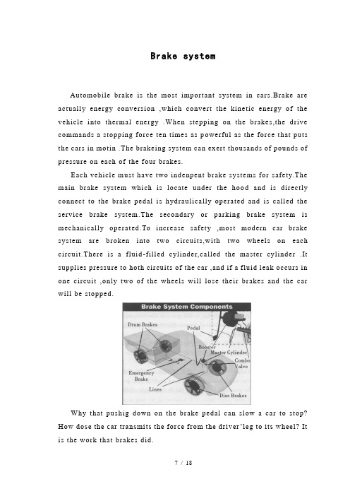
Brake systemAutomobile brake is the most important system in cars.Brake are actually energy conversion ,which convert the kinetic energy of the vehicle into thermal energy .When stepping on the brakes,the drive commands a stopping force ten times as p owerful as the force that puts the cars in motin .The brakeing system can exert thousands of pounds of pressure on each of the four brakes.Each vehicle must have two indenpent brake s ystems for safety.The main brake s ystem which is locate under the hoo d and is directly connect to the brake pedal is hydraulically operated and is called the service brake system.The secondary or parking brake system is mechanically operated.To increase safety ,most modern car brake system are broken into two circuits,with two wheels on each circuit.There is a fluid-filled cylinder,called the master cylinder .It supplies pressure to hoth circuits of the car ,and if a fluid leak occurs in one circuit ,only two of the wheels will lose their brakes and the car will be stopped.Why that pushig down on the brake pedal can slow a car to stop? How dose the car transmits the force from the driver’leg to its wheel? It is the work that brakes did.Layout of Typical Brake system When depressing the breke pedal ,the car transmits the force the drive’s foot to its brakes through a fluid.Since the actual brakes require a much greater force than the drive could apply with his leg ,the car must also multipy the force of the driver’s foot.It dose this in two ways: mechanical advantage a nd hydraulic force multiplication .Leverge The pedal is designed in such a way that it can multiply the force from the driver’s leg several times before any force is even transmitted to the brake fluid.In the figure above ,a force F is being applied t o the left end of the lever.The left end of the lever is twice as long 2X) as the right end (x).Therefore ,on the right end of the lever a force of 2F is available,but it acts through half of the distans (Y) that the left end moves (2Y) .Changing the relat ive lengths of the left and right ends of the lever changes the mulitipliers.Hydraulic Brake Systems The hydraulic system is that force applied at one point is thansmitted to another point using an incompressible fluid , almost alwaays an oil of some so rt .Most brake systems also muitiply the force in the process .The great thing about hydraulic systems is that the pipe connecting the two cylinders can be any length and shape , allowing it to snake through all sorts of things separating the two pistons .The pipe can also fork ,so that one master cylinder can drive more than one salve cylinder if desired .The other neat thing about a hydraulic s ystem is that it makes force multiplicationfairly eas y . In a hydralic system , all you have to do change the si ze of one piston and cylinder to the other .The automobile brake systems are divided into three t ypes of service brake combinations:drum brake , disc brakes and disc-drum combinations.Drum Brake It uses an internal expanding brake shoe with the lining attactet , working within the confines of a rotating brake surface called a brake drum .The brake shoe diameter is expanded to contact the brake surface by a hydraulic cylinder that is referred to as a wheel cylinder . With drum brake , the fluid is forced into the wheel cylinde which pushed the brake shoes out so that the friction lining are pressed againtst the drum , and cause the wheel to stop .Power brakes back in the day , when most cars had drum brakes ,power brakes were not really necessary ---- drum brakes naturally provide some of their own power assist .Since most cars today have disc brakes ,at least on the front wheels , they need power brakes,Without this device ,a lot of drivers would have very tired legs .The brake booster use Vacuum from the engine to multipiy the force that your foot applies to the master cylinder .Disc Brakes Most modern cars have disc brake on the front wheels , and some have disc brakes on all four wheels ,Disc brakes employ a brake disc that rotates with the wheel ,so it is usually referred to as a brake rotor . On a disc brake , the fluid from the master cylinder is forced into a caliper where it presses against a piston ,in—turn , squeezes two brake pads against the disk which is attached to the wheel ,forcing it to slow down or stop .This process is similar to a bicycle brake where two rubber pads rub against the wheel rim creating friction.The most common type of disc brake on modern cars is the single-piston floating caliper.Self-Adjusting brakes The single-piston floating-caliper disc brake is self-centering and self-adjusting .The caliper is able to slide from side to side so it will move to the center each time the brakes are applied .Also,since there is no spring to pull the pads away from the disc ,the pads always stay in light contact with the rotor .This is important because the pistons in the brakes are much larger in diameter than the ones in the master cylinder .If the brake pistons retracted into their cylinders ,it might take several applications of the brake pedal to pump enough fluid into the brake cylinder to engage the brake pads.Self-Adjusting disc brake Older cars had dual or four-pistin fixed-caliper desiger .A piston on each side of the rotor pushed the padon that side .This design has b een largel y eliminated becausesingle-piston designs are cheaper and more reliable .Emergence Brakes In cars with disc brakes on all four wheels ,an emergency brake has to be actuated by a separate mechanism than the primary brakes in case of a total pr imary brake failure .Most cars use a cable to actuate the emergency brake .Some cars with four-wheel disc brakes have a separate drum brake integrated into the hub of the rear wheels .This drum brake is only for the emergency brake sysem ,and it is actuate d only by the cable;it has no hydraulics .Parking Brakes Cars also have the parking brake system .It is used to hold one or more of the vehicle brakes in an applied position for an extended period of time .This brake system must be capable of holding the vehicle on a grade and bringing the vehicie to a stop if the service brakes fail .The parking brake system used on most current model passenger vehicles operates by applying two rear-wheel brakes through a mechanical system of cable and levers.There are air brakes,anti-lock brakes,too .The forme used in heavy trucks and utilizes compressed air as a source of force to stop the truck .The latter used for solving the lockup problem: it can rapidly pump the brakes whenever the system detects a wheel that is locked up .This pumping of the brakes occurs at ten or more times a second ,far fasrer than a human can pump the brake manually.Post-Sale Service and CallbackThe automobile post-sale service means the sale branch provides all the technical service to the customer before or after they buy the car .It may carry on in pre-sale ,or when selling carries on .What but are more is sells after the vehicles ,cerris on the quality guarantee ,the routine maintenance ,the repair ,the technical consultation and the spare parts supply according to the deadline and so on a series of work .In recent years ,the products performances ,product qualities and product prices are almost convergence the same among those famous international automobile compani es .As a result ,the focus of competition in the market focus and transfer to post-sale .Post-sale functions should be enable to use good car products and to create the best returns ,and thus can prove the successful post-sale work .A perfect post-sale service should have two function : to serve both customers and companies themselves .For customers ,the post-sale service could satisfy them and help them solve problems ;for the companies themselves ,it could accurately reflect product utility information ,quality information ,and important social information ,so that the company can make right decisions based on them .Automobile is the most typical product which highl y unifies thesale and the post-sale service .In the intermation market ,one important criterion for automobile sale agent is whethe they have and fulfill post-sale service .When a customer wants to purchase a car ,the first thing he asks is where to repaire the car and whether there are spare-parts .Only getting postive replies ,will he think of other things .Big automobile companies from Eupope ,the US and Japan all recognize that the first car is sold by sales personnel ,but the second car mainly relies on good post-sale service .The automobile is a big product ,so it is very difficult to f ulfill all kinds of post-sale service only depending upon manufaturers .Usually ,a service network undertakes all technical service for manufacturers.In foreign countries ,the post-sale service network is usually linked with sales network .So it can provid e technical service while selling automobile .And the post-sale service network is composed by distributors ,agents and repairing shops .Post-sale service itself belongs to the technical service category.Automobile is hightly technology-intensive ,so the post-sale service includes technical guidance ,technical consultation ,and technical demonstration and so on .Main points which need to be introduced to the society ,dealers ,post-sale service network and customers are completely done by post-sale department .On the other hand ,as a post-sale service man ,one should make sure that you have satisfied your customers when doing your work ,and should make it clear that you want to know if there are any problems with you work ,no matter when they develop .Since you made the project ,you are naturally the best person to service it ,if and when the need arises .Make this clear to your client .Nobody likes callbacks ,and if you’ve done your job well ,you should have few ,if any ,for months or years after the in stallation or delivery.But let the client know that for repairs that result fromordinary use ,you’ll be glad to keep your work looking and working like new---for a modest fee ,of course .If ,however ,problems arise that are clearl y due to shoddy workmanship ,it is incumbent on you to correct them free of charge .This is ,of course ,perhaps the best reason to get it right the first time .There’s no trick to determine whether you are being called back because of a problem due to you workmanship or the clie nt’t use of the unit .Like everything else we’ve covered in this series ,doing right by your customers is just a matter of honesty .Put honesty into practice as part of your selling system and you’ll find that it is the best way to do what is right for you r business ,too .A checklist for maintaining good customer relations:Do anything you can to help the client visualize in advance how the finished project will look .Don’t give ballpark prices unless you already have a well established relationship with the client .Use customers as references ,but only when you are sure they are totally satisfied.Tell customers you want to know if there are problems with your work and that you can provide any routine service .In everything you do ,be honest with your c lient .Automobile callback system originated from the U.S in 1960s .Now it is not new in the U.S.,European countries ,Japan and South Korea .The U.S.has the longest history of automobile callback and the most strict regulations .Until now ,the American gr and has totally recalled more than 200 million vehicles since 1966 ,and more than 24 million tires ,including passenger vehicle ,trucks ,buses ,motorcycles and so on ,And nearly all auto manufactures in the world have recalled cases in the U.S.China’s Fla w Automobile Prosuct Management Stipulation wasimplemented since October1 ,2004 .Automobile is the machine which is assembled by tens of thousands of components and it is not strang to have this kind of flaw or that kind in materials or designs .But most flaws are recessive ,so they will be gradually exposed after using a period of time and people can then realize the flaw’s existence .Sometimes some batch of vehicle components processing ,assembly or material formula change ,and they possibly bring the flaws .The scope of callback s ystem is extremely explicit ,that is the flaw has to be associated with safet y and should appear in the batch .Recall system mainly aims at the systematic and unified flaws which are related with safety and existing in one batch of vehicles .The goal of the automobile recall is to eliminate the flaw and hidden danger ,ensure the public security ,the public benefit and the social economic order .制动系统制动系统是汽车中最重要的系统,它实际上是个能量转换装置,它把动能转化为内能。
车辆工程外文翻译---制动系统
附录1Brake Systems1.Drum vs. DiscBrake technology, just like suspension technology and fuel-system technology, has come a long way in recent years.1)Drum BrakesEarly automotive brake systems, after the era of hand levers of course, used a drum design at all four wheels. They were called drum brakes because the components were housed in a round drum that rotated along with the wheel. Inside was a set of drum that, when the brake pedal was pressed, would force the shoes against the drum and slow the wheel. Fluid was used to transfer the movement of the brake pedal into the movement of the brake shoes, while the drum themselves were made of heat-resistant friction material similar to that used on clutch plates.This basic design proved capable under most circumstances, but it had one major flaw. Under high braking conditions, like descending a steep hill with a heavy load or repeated high-speed slow downs, drum brakes would often fade and lose effectiveness. Usually this fading was the result of too much heat build-up within the shoes. Remember that the principle of braking involves turning kinetic energy (wheelmovement) into thermal energy (heat). For this reason, drum brakes can only operate as long as they can absorb the heat generated by slowing a vehicle's wheels. Once the brake components themselves become saturated with heat, they lose the ability to halt a vehicle, which can be somewhat disconcerting to the vehicle's operator.2) Disc BrakesDisc brakes are used on the front wheels of most cars and on all four wheels onmany cars. A disc rotor is attached to the wheel hub and rotates with the tire and wheel. When the driver applies the brakes, hydraulic pressure from the master cylinder is used to push friction linings against the rotor to stop it.In the disc brake rotor assembly, the rotor is usually made of cast iron. The hub may be manufactured as one piece with the rotor or in two parts. The rotor has a machined braking surface on each face. A splash shield, mounted to the steering knuckle, protects the rotor from road splash.A rotor may be solid or ventilated. Ventilated designs have cooling fins cast between the braking surfaces. This construction considerably increases the cooling area of the rotor casting. Also, when the wheel is in motion, the rotation of these fan-type fins in the rotor provides increased air circulation and more efficient cooling of the brake. Disc brakes do not fade even after rapid, hard brake applications because of the rapid cooling of the rotor.The hydraulic and friction components are housed in a caliper assembly. The caliper assembly straddles the outside diameter of the hub and rotor assembly. When the brakes are applied, the pressure of the pistons is exerted through the shoes in a 'clamping'action on the rotor. Because equal opposed hydraulic pressures are applied to both faces of the rotor throughout application, no distortion of the rotor occurs, regardless of the severity or duration of application. There are many variations of caliper designs, but they can all be grouped into two main categories: moving and stationary caliper. The caliper is fixed in one position on the stationary design. In the moving design, the caliper moves in relation to the rotor.Most late-model cars use the moving caliper design. This design uses a single hydraulic piston and a caliper that can float or slide during application. Floating designs`float'or move on pins or bolts. In sliding designs, the caliper slides sideways on machined surfaces. Both designs work in basically the same way.In the single piston floating caliper, the single-piston caliper assembly is constructed from a single casting that contains one large piston bore in the inboard section of the casting. Inboard refers to the side of the casting nearest the center line of the car when the caliper is mounted. A fluid inlet hole and bleeder valve hole are machined into the inboard section of the caliper and connect directly to the piston bore.The caliper cylinder bore contains a piston and seal. The seal has a rectangular cross section. It is located in a groove that is machined in the cylinder bore. The sealfits around the outside diameter of the piston and provides a hydraulic seal between the piston and the cylinder wall. The rectangular seal provides automatic adjustment of clearance between the rotor and shoe and linings following each application. When the brakes are applied, the caliper seal is deflected by the hydraulic pressure and it inside diameter rides with the piston within the limits of its retention in the cylinder groove. When hydraulic pressure is released, the seal relaxes and returns to its original rectangular shape, retracting the piston into the cylinder enough to provide proper running clearance.As brake linings wear, piston travel tends to exceed the limit of deflection of the seal; the piston therefore slides in the seal to the precise extent necessary to compensate for lining wear.The top of the piston bore is machined to accept a sealing dust boot. The piston in many calipers is steel, precision ground, and nickel chrome plated, giving it a very hard and durable surface. Some manufacturers are using a plastic piston. This is much lighter than steel and provides for a much lighter brake system. The plastic piston insulates well and prevents heat from transferring to the brake fluid. Each caliper contains two shoe and lining assemblies. They are constructed of a stamped metal shoe with the lining riveted or bonded to the shoe and are mounted in the caliper on either side of the rotor. One shoe and lining assembly is called the inboard lining because it fits nearest to the center line of the car. The other is called the outboard shoe and lining assembly.The application and release of the brake pressure actually causes a very slight movement of the piston and caliper. Upon release of the braking effort, the piston and caliper merely relax into a released position. In the released position, the shoes do not retract very far from the rotor surfaces.As the brake lining wears, the piston moves out of the caliper bore and the caliper repositions itself on the mounting bolts an equal distance toward the car. This way, the caliper assembly maintains the inboard and outboard shoe and lining in the same relationship with the rotor surface throughout the full length of the lining.Sliding calipers are made to slide back and forth on the steering knuckle support to which it is mounted. There is a V shaped surface, sometimes called a rail, on the caliper that matches a similar surface on the steering knuckle support. These two mating surfaces allow the caliper to slide in and out. The internal components of the caliper are the same as those previously described.The stationary or fixed caliper has a hydraulic piston on each side of the rotor. Larger calipers may have two pistons on each side of the rotor. The inboard and outboard brake shoes are pushed against the rotor by their own pistons. The caliper is anchored solidly and does not move. The seals around the pistons work just like those already described. The main disadvantage of the stationary caliper is that it has more hydraulic components. This means they are more expensive and have more parts to wear out .2.Other Components in the Hydraulic System:1)Proportioning Valve or Equalizer ValveThese valves are mounted between the master cylinder and the rear wheels. They are designed to adjust the pressure between the front and rear brakes depending on how hard you are st opping. The shorter you stop, the more of the vehicle’s weight is transferred to the front wheels, in some cases, causing the rear to lift and the front to dive. These valves are designed to direct more pressure to the front and less pressure to the rear the harder you stop. This minimizes the chance of premature lockup at the rear wheels.2)Pressure Differential ValveThis valve is usually mounted just below the master cylinder and is responsible for turning the brake warning light on when it detects a malfunction. It measures the pressure from the two sections of the master cylinder and compares them. Since it is mounted ahead of the proportioning or equalizer valve, the two pressures it detects should be equal. If it detects a difference, it means that there is probably a brake fluid leak somewhere in the system.3)Combination ValveThe Combination valve (Figure) is simply a proportioning valve and a pressure differential valve that is combined into one unit.The parking brake (a.k.a.emergency brake ) system controls the rear brakes through a series of steel cables that are connected to either a hand lever or a foot pedal. The idea is that the system is fully mechanical and completely bypasses the hydraulic system so that the vehicle can be brought to a stop even if there is a total brake failure.On drum brakes, the cable pulls on a lever mounted in the rear brake and is directly connected to the brake shoes. This has the effect of bypassing the wheel cylinder and controlling the brakes directly.Disk brakes on the rear wheels add additional complication for parking brakesystems. There are two main designs for adding a mechanical parking brake to rear disk brakes. The first type uses the existing rear wheel caliper and adds a lever attached to a mechanical corkscrew device inside the caliper piston. When the parking brake cable pulls on the lever, this corkscrew device pushes the piston against the pads, thereby bypassing the hydraulic system, to stop the vehicle. This type of system is primarily used with single piston floating calipers, if the caliper is of the four piston fixed type, then that type of system can’t be used. The other system uses a complete mechanical drum brake unit mounted inside the rear rotor. The brake shoes on this system are connected to a lever that is pulled by the parking brake cable to activate the brakes. The brake “drum” is actually the inside part of the rear brake rotor.On cars with automatic transmissions, the parking brake is rarely used. This can cause a couple of problems. The biggest problem is that the brake cables tend to get corroded and eventually seize up causing the parking brake to become inoperative. By using the parking brake from time to time, the cables stay clean and functional. Another problem comes from the fact that the self adjusting mechanism on certain brake systems uses the parking brake actuation to adjust the brakes. If the parking brake is never used, then the brakes never get adjusted.The power brake booster (Figure) is mounted of the firewall directly behind the master cylinder and, along with the master cylinder, is directly connected with the brake pedal. Its purpose is to amplify the available foot pressure applied to the brake pedal so that the amount of foot pressure required to stop even the largest vehicle is minimal. Power for the booster comes from engine vacuum. The automobile engine produces vacuum as a by-product of normal operation and is freely available for use in powering accessories such as the power brake booster. Vacuum enters the booster through a check valve on the booster. The check valve is connected to the engine with a rubber hose and acts as a one-way valve that allows vacuum to enter the booster but dose not let it escape. The booster is an empty shell that is divided into two chambers by a rubber diaphragm. There is a valve in the diaphragm that remains open while foot is off the brake pedal so that vacuum is allowed to fill both chambers. When stepping on the brake pedal, the valve in the diaphragm closes, separating the two chambers and another valve opens to allow air in the chamber on the brake pedal side. This is what provides the power assist. Power boosters are very reliable and cause few problems of their own. However, other things cam contribute to a loss of power assist. In order to have power assist, the engine must be running. If the engine stalls or shutsoff while you are driving, you will have a small reserve of power assist for two or three pedal applications but, after that, the brakes will be extremely hard to apply and you must put as much pressure as you can to bring the vehicle to a stop.The last topic is the Anti-Lock Brakes (ABS). The most efficient braking pressure takes place just before each wheel lock up. When you slam on the brakes in a panic stop and the wheels lock up, causing a screeching sound and leaving strips of rubber on the pavement, you do not stop the vehicle nearly as short as it is capable of stopping. Also, while the wheels are locked up, you loose all steering control so that , if you have an opportunity to steer around the obstacle, you will not be able to do so. Another problem occurs during an extended skid is that you will burn a patch of rubber off the tire which causes a “flat spot” on the tread that will produce an annoying thumping sound as you drive.Anti-lock brake systems solve this lockup problem by rapidly pumping the brakes whenever the system detects a wheel that is locked up. In most cases, only the wheel that is locked will be pumped, while full braking pressure stays available to the other wheels. This effect allows you to stop in the shortest amount of time while maintaining full steering control even if one or more wheels are on ice. The system uses a computer to monitor the speed of each wheel. When it detects that one or more wheels have stopped or are turning much slower than the remaining wheels, the computer sends a signal to momentarily remove and reapply or pulse the pressure to the affected wheels to allow them to continue turning. This “pumping” of the brakes occurs at tem or more times a second, far faster then a human can pump the brakes manually. If you step on the brakes hard enough to engage the anti-lock system, you may feel a strong vibration in the brake pedal. This is a normal condition and indicates that the system is working; however, it can be disconcerting to some people who don’t expect it. If your vehicle has anti-lock brakes, read your owner’s manual to find out more about it.The system consists of am electronic control unit, a hydraulic actuator, and wheel speed sensors at each wheel. If the control unit detects a malfunction in the system, it will illuminate an ABS warming light on the dash to let you know that there is a problem. If there is a problem, the antilock system will not function but the brakes will otherwise function normally.3.Friction materialsBrake shoes and pads are constructed in a similar manner. The pad or shoe iscomposed of a metal backing plate and a friction lining. The lining is either bonded (glued) to the metal, or riveted. Generally, riveted linings provide superior performance, but good quality bonded linings are perfectly adequate.Friction materials will vary between manufacturers and type of pad and the material compound may be referred to as: asbestos, organic, semi-metallic, metallic. The difference between these compounds lies in the types and percentages of friction materials used, material binders and performance modifiers.Generally speaking, organic and non-metallic asbestos compound brakes are quiet, easy on rotors and provide good feel. But this comes at the expense of high temperature operation, so they may not be your best choice for heavy duty use or mountain driving. In most cases, these linings will wear somewhat faster than metallic compound pads, so you will usually replace them more often. But, when using these pads, rotors tend to last longer.Semi-metallic or metallic compound brake linings will vary in performance based on the metallic contents of the compound. Again, generally speaking, the higher the metallic content, the better the friction material will resist heat. This makes them more appropriate for heavy duty applications, but at the expense of braking performance before the pad reaches operating temperature. The first few applications on a cold morning may not give strong braking. Also, metallic and semi-metallic are more likely to squeal. In most cases, metallic compounds last longer than non-metallic pads, but they tend to cause more wear on the rotors. If you use metallic pads, expect to replace the rotors more often.When deciding what type of brake lining is right for you, keep in mind that today's modern cars have brake materials which are matched to the expected vehicle's performance capabilities. Changing the material from OEM specification could adversely affect brake feel or responsiveness. Before changing the brake materials, talk to your dealer or parts supplier to help decide what is most appropriate for your application. Remember that heavy use applications such as towing, stop and go driving, driving down mountain roads, and racing may require a change to a higher performance material.Some more exotic materials are also used in brake linings, among which are Kevlar and carbon compounds. These materials have the capability of extremely good performance for towing, mountain driving or racing. Wear characteristics can be similar to either the metallic or the non-metallic linings, depending on the product youbuy. Most race applications tend to wear like metallic linings, while many of the street applications are more like the non-metallic制动系统1. 刹车:鼓与盘制动技术,就像悬浮技术和燃料系统技术,已走过了漫长的道路1)鼓式制动器早在后时代,手杠杆的汽车制动系统用鼓装在所有的四个车轮。
汽车工程专业英语—李俊玲版(1-3章)词组
点燃式&火花塞点火
3. compression-ignition
压燃式
4. power unit
动力装置
5. engine configuration
发动机布置
Automotive engineering English
Chapter 1 Automotive Basics
汽车英语专业词组
1.3.1
3. valve insert
气门座
4. cam follower
凸轮挺杆
5. rocker arm
摇臂
6. valve stem
阀杆
7. gas-tight seal
气封 气密密封
8. valve clearance
气门间隙
9. valve timing
气门正时
10. intake/exhaust valve
电子系统 充电电路 电气部分 电子组件 稳压器;调压器(电压) 低压电路 原电路 点火线圈
火花塞
Automotive engineering English
Chapter 2 Internal Combustion Engine
汽车英语专业词组
2.1
1. chemical energy 2. internal combustion engine 3. inlet valve 4. exhaust valve 5. TDC 6. BDC 7. swept volume 8. engine capacity 9. clearance volume 10. compression ratio
惯性力 侧向力 切向力 径向力 &法向力 活塞环 活塞总成 钢圈 活塞销 活塞销凸台 活塞环槽
(完整版)汽车制动系统英文文献及翻译)

Automobile Brake SystemThe braking system is the most important system in cars. If the brakes fail, the result can be disastrous. Brakes are actually energy conversion devices, which convert the kinetic energy (momentum) of the vehicle into thermal energy (heat).When stepping on the brakes, the driver commands a stopping force ten times as powerful as the force that puts the car in motion. The braking system can exert thousands of pounds of pressure on each of the four brakes.Two complete independent braking systems are used on the car. They are the service brake and the parking brake.The service brake acts to slow, stop, or hold the vehicle during normal driving. They are foot-operated by the driver depressing and releasing the brake pedal. The primary purpose of the brake is to hold the vehicle stationary while it is unattended. The parking brake is mechanically operated by when a separate parking brake foot pedal or hand lever is set.The brake system is composed of the following basic components: t he “master cylinder” which is located under the hood, and is directly connected to the brake pedal, converts driver foot’s mechanical pressure into hydraulic pressure. Steel “brake lines” and flexible “brake hoses” connect the master cylinder to the “slave cylinders” located at each wheel. Brake fluid, specially designed to work in extreme conditions, fills the system. “Shoes” and “pads” are pushed by the slave cylinders to contact the “drums” and “rotors” thus causing drag, which (hopefully) slows the car.The typical brake system consists of disk brakes in front and either disk or drum brakes in the rear connected by a system of tubes and hoses that link the brake at each wheel to the master cylinder (Figure).Basically, all car brakes are friction brakes. When the driver applies the brake, the control device forces brake shoes, or pads, against the rotating brake drum or disks at wheel. Friction between the shoes or pads and the drums or disks then slows or stops the wheel so that the car is braked.In most modern brake systems (see Figure 15.1), there is a fluid-filled cylinder, called master cylinder, which contains two separate sections, there is a piston in each section and both pistons are connected to a brake pedal in the driver’s compartment. When th e brake is pushed down, brake fluid is sent from the master cylinder to the wheels.At the wheels, the fluid pushes shoes, or pads, against revolving drums or disks. The friction between the stationary shoes, or pads, and the revolving drums or disks slows and stops them. This slows or stops the revolving wheels, which, in turn, slow or stop the car.The brake fluid reservoir is on top of the master cylinder. Most cars today have a transparent r reservoir so that you can see the level without opening the cover. The brake fluid level will drop slightly as the brake pads wear. This is a normal condition and no cause for concern. If the level drops noticeably over ashort period of time or goes down to about two thirds full, have your brakes checked as soon as possible. Keep the reservoir covered except for the amount of time you need to fill it and never leave a cam of brake fluid uncovered. Brake fluid must maintain a very high boiling point. Exposure to air will cause the fluid to absorb moisture which will lower that boiling point.The brake fluid travels from the master cylinder to the wheels through a series of steel tubes and reinforced rubber hoses. Rubber hoses are only used in places that require flexibility, such asat the front wheels, which move up and down as well as steer. The rest of the system uses non-corrosive seamless steel tubing with special fittings at all attachment points. If a steel line requires a repair, the best procedure is to replace the compete line. If this is not practical, a line can be repaired using special splice fittings that are made for brake system repair. You must never use copper tubing to repair a brake system. They are dangerous and illegal.Drum brakes, it consists of the brake drum, an expander, pull back springs, a stationary back plate, two shoes with friction linings, and anchor pins. The stationary back plate is secured to the flange of the axle housing or to the steering knuckle. The brake drum is mounted on the wheel hub. There is a clearance between the inner surface of the drum and the shoe lining. To apply brakes, the driver pushes pedal, the expander expands the shoes and presses them to the drum. Friction between the brake drum and the friction linings brakes the wheels and the vehicle stops. To release brakes, the driver release the pedal, the pull back spring retracts the shoes thus permitting free rotation of the wheels.Disk brakes, it has a metal disk instead of a drum. A flat shoe, or disk-brake pad, is located on each side of the disk. The shoes squeeze the rotatin g disk to stop the car. Fluid from the master cylinder forces the pistons to move in, toward the disk. This action pushes the friction pads tightly against the disk. The friction between the shoes and disk slows and stops it. This provides the braking action. Pistons are made of either plastic or metal. There are three general types of disk brakes. They are the floating-caliper type, the fixed-caliper type, and the sliding-caliper type. Floating-caliper and sliding-caliper disk brakes use a single piston. Fixed-caliper disk brakes have either two or four pistons.The brake system assemblies are actuated by mechanical, hydraulic or pneumatic devices. The mechanical leverage is used in the parking brakes fitted in all automobile. When the brake pedal is depressed, the rod pushes the piston of brake master cylinder which presses the fluid. The fluid flows through the pipelines to the power brake unit and then to the wheel cylinder. The fluid pressure expands the cylinder pistons thus pressing the shoes to the drum or disk. If the pedal is released, the piston returns to the initialposition, the pull back springs retract the shoes, the fluid is forced back to the master cylinder and braking ceases.The primary purpose of the parking brake is to hold the vehicle stationary while it is unattended. The parking brake is mechanically operated by the driver when a separate parking braking hand lever is set. The hand brake is normally used when the car has already stopped. A lever is pulled and t he rear brakes are approached and locked in the “on” position. The car may now be left without fear of its rolling away. When the driver wants to move the car again, he must press a button before the lever can be released. The hand brake must also be able to stop the car in the event of the foot brake failing. For this reason, it is separate from the foot brake uses cable or rods instead of the hydraulic system.Anti-lock Brake SystemAnti-lock brake systems make braking safer and more convenient, Anti-lock brake systems modulate brake system hydraulic pressure to prevent the brakes from locking and the tires from skidding on slippery pavement or during a panic stop.Anti-lock brake systems have been used on aircraft for years, and some domestic car were offered with an early form of anti-lock braking in late 1990’s. Recently, several automakers have introduced more sophisticated anti-lock system. Investigations in Europe, where anti-lock brakin g systems have been available for a decade, have led one manufacture to state that the number oftraffic accidents could be reduced by seven and a half percent if all cars had anti-lock brakes. So some sources predict that all cars will offer anti-lock brakes to improve the safety of the car.Anti-lock systems modulate brake application force several times per second to hold the tires at a controlled amount of slip; all systems accomplish this in basically the same way. One or more speed sensors generate alternating current signal whose frequency increases with the wheel rotational speed. An electronic control unit continuously monitors these signals and if the frequency of a signal drops too rapidly indicating that a wheel is about to lock, the control unit instructs a modulating device to reduce hydraulic pressure to the brake at the affected wheel. When sensor signals indicate the wheel is again rotating normally, the control unit allows increased hydraulic pressure to the brake. This release-apply cycle occurs several time per second to “pump” the brakes like a dr iver might but at a much faster rate.In addition to their basic operation, anti-lock systems have two other things in common. First, they do not operate until the brakes are applied with enough force to lock or nearly lock a wheel. At all other times, the system stands ready to function but does not interfere with normal braking. Second, if the anti-lock system fail in any way, the brakes continue to operate without anti-lock capability. A warning light on the instrument panel alerts the driver when a problem exists in the anti-lock system.The current Bosch component Anti-lock Braking System (ABSⅡ), is a second generation design wildly used by European automakers such as BWM, Mercedes-Benz and Porsche. ABSⅡsystem consists of : four wheel speed sensor, electronic control unit and modulator assembly.A speed sensor is fitted at each wheel sends signals about wheel rotation to control unit. Each speed sensor consists of a sensor unit and a gear wheel. The front sensor mounts to the steering knuckle and its gear wheel is pressed onto the stub axle that rotates with the wheel. The rear sensor mounts the rear suspension member and its gear wheel is pressed onto the axle. The sensor itself is a winding with a magnetic core. The core creates a magnetic field around the winding, and as the teeth of the gear wheel move through this field, an alternating current is induced in the winding. The control unit monitors the rate o change in this frequency to determine impending brake lockup.The control unit’s functi on can be divided into three parts: signal processing, logic and safety circuitry. The signal processing section is the converter that receives the alternating current signals form the speed sensors and converts them into digital form for the logic section. The logic section then analyzes the digitized signals to calculate any brake pressure changes needed. If impending lockup is sensed, the logic section sends commands to the modulator assembly.Modulator assemblyThe hydraulic modulator assembly regulates pressure to the wheel brakes when it receives commands from the control utuit. The modulator assembly can maintain or reduce pressure over the level it receives from the master cylinder, it also can never apply the brakes by itself. The modulator assembly consists of three high-speed electric solenoid valves, two fluid reservoirs and a turn delivery pump equipped with inlet and outlet check valves. The modulator electrical connector and controlling relays are concealed under a plastic cover of the assembly.Each front wheel is served by electric solenoid valve modulated independently by the control unit. The rear brakes are served by a single solenoid valve and modulated together using the select-low principle. During anti-braking system operation, the control unit cycles the solenoid valves to either hold or release pressure the brake lines. When pressure is released from the brakelines during anti-braking operation, it is routed to a fluid reservoir. There is one reservoir for the front brake circuit. The reservoirs are low-pressure accumulators that store fluid under slight spring pressure until the return delivery pump can return the fluid through the brake lines to the master cylinder.汽车制动系统制动系统是汽车中最重要的系统。
汽车制动系统英文文献及翻译

汽车制动系统-英文文献及翻译————————————————————————————————作者:————————————————————————————————日期:Brake systemsWe all know that pushing down on the brake pedal slows a car to a stop. But how does this happen? How does your car transmit the force from your leg to its wheels? How does it multiply the force so that it is enough to stop something as big as a car?Brake Image GalleryLayout of typical brake system. See more brake images.When you depress your brake pedal, your car transmits the force from your foot to its brakes through a fluid. Since the actual brakes require a much greater force than you could apply with your leg, your car must also multiply the force of your foot. It does this in two ways:•Mechanical advantage (leverage)•Hydraulic force multiplicationThe brakes transmit the force to the tires using friction, and the tires transmit that force to the road using friction also. Before we begin our discussion on the components of the brake system, we'll cover these three principles:•Leverage•Hydraulics•FrictionLeverage and HydraulicsIn the figure below, a force F is being applied to the left end of the lever. The left end of the lever is twice as long (2X) as the right end (X). Therefore, on the right end of the lever a force of 2F is available, but it acts through half of the distance (Y) that the left end moves (2Y). Changing the relative lengths of the left and right ends of the lever changes the multipliers.The pedal is designed in such a way that it can multiply the force from yourleg several times before any force is even transmitted to the brake fluid.The basic idea behind any hydraulic system is very simple: Force applied at one point is transmitted to another point using an incompressible fluid, almost always an oil of some sort. Most brake systems also multiply the force in the process. Here you can see the simplest possible hydraulic system:Your browser does not support JavaScript or it is disabled.Simple hydraulic systemIn the figure above, two pistons (shown in red) are fit into two glass cylinders filled with oil (shown in light blue) and connected to one another with an oil-filled pipe. If youapply a downward force to one piston (the left one, in this drawing), then the force is transmitted to the second piston through the oil in the pipe. Since oil is incompressible, the efficiency is very good -- almost all of the applied force appears at the second piston. The great thing about hydraulic systems is that the pipe connecting the two cylinders can be any length and shape, allowing it to snake through all sorts of things separating the twopistons. The pipe can also fork, so that one master cylinder can drive more than one slave cylinder if desired, as shown in here:Your browser does not support JavaScript or it is disabled.Master cylinder with two slavesThe other neat thing about a hydraulic system is that it makes force multiplication (or division) fairly easy. If you have read How a Block and Tackle Works or How Gear Ratios Work, then you know that trading force for distance is very common in mechanical systems. In a hydraulic system, all you have to do is change the size of one piston and cylinder relative to the other, as shown here:Your browser does not support JavaScript or it is disabled.Hydraulic multiplicationTo determine the multiplication factor in the figure above, start by looking at the size of the pistons. Assume that the piston on the left is 2 inches (5.08 cm) in diameter (1-inch / 2.54 cm radius), while the piston on the right is 6 inches (15.24 cm) in diameter (3-inch / 7.62 cm radius). The area of the two pistons is Pi * r2. The area of the left piston is therefore 3.14, while the area of the piston on the right is 28.26. The piston on the right is nine times larger than the piston on the left. This means that any force applied to theleft-hand piston will come out nine times greater on the right-hand piston. So, if you apply a 100-pound downward force to the left piston, a 900-pound upward force will appear on the right. The only catch is that you will have to depress the left piston 9 inches (22.86 cm) to raise the right piston 1 inch (2.54 cm).A Simple Brake SystemBefore we get into all the parts of an actual car brake system, let's look at a simplified system:Your browser does not support JavaScript or it is disabled.A simple brake systemYou can see that the distance from the pedal to the pivot is four times the distance from the cylinder to the pivot, so the force at the pedal will be increased by a factor of four before it is transmitted to the cylinder.You can also see that the diameter of the brake cylinder is three times the diameter of the pedal cylinder. This further multiplies the force by nine. All together, this system increases the force of your foot by a factor of 36. If you put 10 pounds of force on the pedal, 360 pounds (162 kg) will be generated at the wheel squeezing the brake pads.There are a couple of problems with this simple system. What if we have a leak? If it is a slow leak, eventually there will not be enough fluid left to fill the brake cylinder, and the brakes will not function. If it is a major leak, then the first time you apply the brakes all of the fluid will squirt out the leak and you will have complete brake failure.Drum brakes work on the same principle as disc brakes: Shoes press against a spinning surface. In this system, that surface is called a drum.Figure 1. Location of drum brakes. See more drum brakepictures.Many cars have drum brakes on the rear wheels and disc brakes on the front. Drum brakes have more parts than disc brakes and are harder to service, but they are less expensive to manufacture, and they easily incorporate an emergency brake mechanism.In this edition of HowStuffWorks, we will learn exactly how a drum brake system works, examine the emergency brake setup and find out what kind of servicing drum brakes need.Figure 2. Drum brake with drum in placeFigure 3. Drum brake without drum in placeLet's start with the basics.The Drum BrakeThe drum brake may look complicated, and it can be pretty intimidating when you open one up. Let's break it down and explain what each piece does.Figure 4. Parts of a drum brakeLike the disc brake, the drum brake has two brake shoes and a piston. But the drum brake also has an adjuster mechanism, an emergency brake mechanism and lots of springs.First, the basics: Figure 5 shows only the parts that provide stopping power.Your browser does not support JavaScript or it isdisabled.Figure 5. Drum brake in operationWhen you hit the brake pedal, the piston pushes the brake shoes against the drum. That's pretty straightforward, but why do we need all of those springs?This is where it gets a little more complicated. Many drum brakes are self-actuating. Figure 5 shows that as the brake shoes contact the drum, there is a kind of wedging action, which has the effect of pressing the shoes into the drum with more force.The extra braking force provided by the wedging action allows drum brakes to use a smaller piston than disc brakes. But, because of the wedging action, the shoes must be pulled away from the drum when the brakes are released. This is the reason for some of the springs. Other springs help hold the brake shoes in place and return the adjuster arm after it actuates.Brake AdjusterFor the drum brakes to function correctly, the brake shoes must remain close to the drum without touching it. If they get too far away from the drum (as the shoes wear down, for instance), the piston will require more fluid to travel that distance, and your brake pedal will sink closer to the floor when you apply the brakes. This is why most drum brakes have an automatic adjuster.Figure 6. Adjuster mechanismNow let's add in the parts of the adjuster mechanism. The adjuster uses theself-actuation principle we discussed above.Your browser does not support JavaScript or it is disabled.Figure 7. Drum brake adjuster in operationIn Figure 7, you can see that as the pad wears down, more space will form between the shoe and the drum. Each time the car stops while in reverse, the shoe is pulled tight against the drum. When the gap gets big enough, the adjusting lever rocks enough to advance the adjuster gear by one tooth. The adjuster has threads on it, like a bolt, so that it unscrews a little bit when it turns, lengthening to fill in the gap. When the brake shoes wear a little more, the adjuster can advance again, so it always keeps the shoes close to the drum.Some cars have an adjuster that is actuated when the emergency brake is applied. This type of adjuster can come out of adjustment if the emergency brake is not used forlong periods of time. So if you have this type of adjuster, you should apply your emergency brake at least once a week.ServicingThe most common service required for drum brakes is changing the brake shoes. Some drum brakes provide an inspection hole on the back side, where you can see how much material is left on the shoe. Brake shoes should be replaced when the friction material has worn down to within 1/32 inch (0.8 mm) of the rivets. If the friction material is bonded to the backing plate (no rivets), then the shoes should be replaced when they have only 1/16 inch (1.6 mm) of material left.Photo courtesy of a local AutoZone storeFigure 9. Brake shoeJust as in disc brakes, deep scores sometimes get worn into brake drums. If aworn-out brake shoe is used for too long, the rivets that hold the friction material to the backing can wear grooves into the drum. A badly scored drum can sometimes be repaired by refinishing. Where disc brakes have a minimum allowable thickness, drum brakes have a maximum allowable diameter. Since the contact surface is the inside of the drum, as you remove material from the drum brake the diameter gets bigger.Figure 10. Brake drum制动系统众所周知,踩下制动踏板可以使汽车减速至停止。
- 1、下载文档前请自行甄别文档内容的完整性,平台不提供额外的编辑、内容补充、找答案等附加服务。
- 2、"仅部分预览"的文档,不可在线预览部分如存在完整性等问题,可反馈申请退款(可完整预览的文档不适用该条件!)。
- 3、如文档侵犯您的权益,请联系客服反馈,我们会尽快为您处理(人工客服工作时间:9:00-18:30)。
Automobile Brake SystemThe braking system is the most important system in cars. If the brakes fail, the result can be disastrous. Brakes are actually energy conversion devices, which convert the kinetic energy (momentum) of the vehicle into thermal energy (heat).When stepping on the brakes, the driver commands a stopping force ten times as powerful as the force that puts the car in motion. The braking system can exert thousands of pounds of pressure on each of the four brakes.Two complete independent braking systems are used on the car. They are the service brake and the parking brake.The service brake acts to slow, stop, or hold the vehicle during normal driving. They are foot-operated by the driver depressing and releasing the brake pedal. The primary purpose of the brake is to hold the vehicle stationary while it is unattended. The parking brake is mechanically operated by when a separate parking brake foot pedal or hand lever is set.The brake system is composed of the following basic components: the “master cylinder” which is located under the hood, and is directly connected to the brake pedal, converts driver foot’s mechanical pressure into hydraulic pressure. Steel “brake lines” and flexible “brake hoses” connect the master cylinder to the “slave cylinders” located at each wheel. Brake fluid, specially designed to work in extreme conditions, fills the system. “Shoes” and “pads” are pushed by the slave cylinders to contact the “drums” and “rotors” thus causing drag, which (hopefully) slows the car.The typical brake system consists of disk brakes in front and either disk or drum brakes in the rear connected by a system of tubes and hoses that link the brake at each wheel to the master cylinder (Figure).Basically, all car brakes are friction brakes. When he driver applies the brake, the control device forces brake shoes, or pads, against the rotating brake drum or disks at wheel. Friction between the shoes or pads and the drums or disks then slows or stops the wheel so that the car is braked.In most modern brake systems (see Figure 15.1), there is a fluid-filled cylinder, called master cylinder, which contains two separate sections, there is a piston in each section and both pistons are connected to a brake pedal in the driver’s compartment. When the brake is pushed down, brake fluid is sent from the master cylinder to the wheels. At the wheels, the fluid pushes shoes, or pads, against revolving drums ordisks. The friction between the stationary shoes, or pads, and the revolving drums or disks slows and stops them. This slows or stops the revolving wheels, which, in turn, slow or stop the car.The brake fluid reservoir is on top of the master cylinder. Most cars today have a transparent r reservoir so that you can see the level without opening the cover. The brake fluid level will drop slightly as the brake pads wear. This is a normal condition and no cause for concern. If the level drops noticeably over a short period of time or goes down to about two thirds full, have your brakes checked as soon as possible. Keep the reservoir covered except for the amount of time you need to fill it and never leave a cam of brake fluid uncovered. Brake fluid must maintain a very high boiling point. Exposure to air will cause the fluid to absorb moisture which will lower that boiling point.The brake fluid travels from the master cylinder to the wheels through a series of steel tubes and reinforced rubber hoses. Rubber hoses are only used in places that require flexibility, such as at the front wheels, which move up and down as well as steer. The rest of the system uses non-corrosive seamless steel tubing with special fittings at all attachment points. If a steel line requires a repair, the best procedure is to replace the compete line. If this is not practical, a line can be repaired using special splice fittings that are made for brake system repair. You must never use copper tubing to repair a brake system. They are dangerous and illegal.Drum brakes, it consists of the brake drum, an expander, pull back springs, a stationary back plate, two shoes with friction linings, and anchor pins. The stationary back plate is secured to the flange of the axle housing or to the steering knuckle. The brake drum is mounted on the wheel hub. There is a clearance between the inner surface of the drum and the shoe lining. To apply brakes, the driver pushes pedal, the expander expands the shoes and presses them to the drum. Friction between the brake drum and the friction linings brakes the wheels and the vehicle stops. To release brakes, the driver release the pedal, the pull back spring retracts the shoes thus permitting free rotation of the wheels.Disk brakes, it has a metal disk instead of a drum. A flat shoe, or disk-brake pad, is located on each side of the disk. The shoes squeeze the rotating disk to stop the car. Fluid from the master cylinder forces the pistons to move in, toward the disk. This action pushes the friction pads tightly against the disk. The friction between the shoes and disk slows and stops it. This provides the braking action. Pistons are made ofeither plastic or metal. There are three general types of disk brakes. They are the floating-caliper type, the fixed-caliper type, and the sliding-caliper type. Floating-caliper and sliding-caliper disk brakes use a single piston. Fixed-caliper disk brakes have either two or four pistons.The brake system assemblies are actuated by mechanical, hydraulic or pneumatic devices. The mechanical leverage is used in the parking brakes fitted in all automobile. When the brake pedal is depressed, the rod pushes the piston of brake master cylinder which presses the fluid. The fluid flows through the pipelines to the power brake unit and then to the wheel cylinder. The fluid pressure expands the cylinder pistons thus pressing the shoes to the drum or disk. If the pedal is released, the piston returns to the initial position, the pull back springs retract the shoes, the fluid is forced back to the master cylinder and braking ceases.The primary purpose of the parking brake is to hold the vehicle stationary while it is unattended. The parking brake is mechanically operated by the driver when a separate parking braking hand lever is set. The hand brake is normally used when the car has already stopped. A lever is pulled and the rear brakes are approached and locked in the “on” position. The car may now be left without fear of its rolling away. When the driver wants to move the car again, he must press a button before the lever can be released. The hand brake must also be able to stop the car in the event of the foot brake failing. For this reason, it is separate from the foot brake uses cable or rods instead of the hydraulic system.Anti-lock Brake SystemAnti-lock brake systems make braking safer and more convenient, Anti-lock brake systems modulate brake system hydraulic pressure to prevent the brakes from locking and the tires from skidding on slippery pavement or during a panic stop.Anti-lock brake systems have been used on aircraft for years, and some domestic car were offered with an early form of anti-lock braking in late 1990’s. Recently, several automakers have introduced more sophisticated anti-lock system. Investigations in Europe, where anti-lock braking systems have been available for a decade, have led one manufacture to state that the number of traffic accidents could be reduced by seven and a half percent if all cars had anti-lock brakes. So some sources predict that all cars will offer anti-lock brakes to improve the safety of the car.Anti-lock systems modulate brake application force several times per second to hold the tires at a controlled amount of slip; all systems accomplish this in basicallythe same way. One or more speed sensors generate alternating current signal whose frequency increases with the wheel rotational speed. An electronic control unit continuously monitors these signals and if the frequency of a signal drops too rapidly indicating that a wheel is about to lock, the control unit instructs a modulating device to reduce hydraulic pressure to the brake at the affected wheel. When sensor signals indicate the wheel is again rotating normally, the control unit allows increased hydraulic pressure to the brake. This release-apply cycle occurs several time per second to “pump” the brakes like a d river might but at a much faster rate.In addition to their basic operation, anti-lock systems have two other things in common. First, they do not operate until the brakes are applied with enough force to lock or nearly lock a wheel. At all other times, the system stands ready to function but does not interfere with normal braking. Second, if the anti-lock system fail in any way, the brakes continue to operate without anti-lock capability. A warning light on the instrument panel alerts the driver when a problem exists in the anti-lock system.The current Bosch component Anti-lock Braking System (ABSⅡ), is a second generation design wildly used by European automakers such as BWM, Mercedes-Benz and Porsche. ABSⅡsystem consists of : four wheel speed sensor, electronic control unit and modulator assembly.A speed sensor is fitted at each wheel sends signals about wheel rotation to control unit. Each speed sensor consists of a sensor unit and a gear wheel. The front sensor mounts to the steering knuckle and its gear wheel is pressed onto the stub axle that rotates with the wheel. The rear sensor mounts the rear suspension member and its gear wheel is pressed onto the axle. The sensor itself is a winding with a magnetic core. The core creates a magnetic field around the winding, and as the teeth of the gear wheel move through this field, an alternating current is induced in the winding. The control unit monitors the rate o change in this frequency to determine impending brake lockup.The control unit’s function can be divided into three parts: signal processing, logic and safety circuitry. The signal processing section is the converter that receives the alternating current signals form the speed sensors and converts them into digital form for the logic section. The logic section then analyzes the digitized signals to calculate any brake pressure changes needed. If impending lockup is sensed, the logic section sends commands to the modulator assembly.The hydraulic modulator assembly regulates pressure to the wheel brakes when itreceives commands from the control utuit. The modulator assembly can maintain or reduce pressure over the level it receives from the master cylinder, it also can never apply the brakes by itself. The modulator assembly consists of three high-speed electric solenoid valves, two fluid reservoirs and a turn delivery pump equipped with inlet and outlet check valves. The modulator electrical connector and controlling relays are concealed under a plastic cover of the assembly.Each front wheel is served by electric solenoid valve modulated independently by the control unit. The rear brakes are served by a single solenoid valve and modulated together using the select-low principle. During anti-braking system operation, the control unit cycles the solenoid valves to either hold or release pressure the brake lines. When pressure is released from the brake lines during anti-braking operation, it is routed to a fluid reservoir. There is one reservoir for the front brake circuit. The reservoirs are low-pressure accumulators that store fluid under slight spring pressure until the return delivery pump can return the fluid through the brake lines to the master cylinder.汽车制动系统制动系统是汽车中最重要的系统。