Design of Embedded Control System Based on ARM9 Microcontroller
基于嵌入式控制器的便携式卫星通信控制系统设计
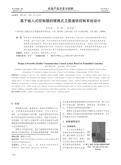
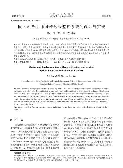
·测试与控制·图1俯仰-方位型天线座架实物图Fig.1The base of two-axisantenna修稿日期:2012-11-27基金项目:国家自然科学基金(61074023);江苏省科技支撑计划资助项目(BE2009160)作者简介:孙钟阜(1965-),男,海军第二炮兵学院毕业,本科学历,高级工程师。
研究方向:水声对抗。
0引言我国幅员辽阔、地理复杂,地质灾害频繁发生且县、乡两级的通信保障非常薄弱,当发生重大灾难时,由于常规通信手段中断、交通不便等原因常常导致卫星应急通讯车无法到达灾害地点。
因此开发适用于应急通信、便于救灾人员随身带入灾区以快速进行远程数据通信和现场视频转播等业务的便携式卫星通信系统已成为重要需求[1,2]。
便携式卫星通信系统,通过与地球同步轨道卫星链路形成卫星通信网络,是实现远程数据传输、事故现场应急通信和现场视频转播等业务的良好手段。
被广泛应用于交通运输、抢险救灾、新闻采访、科考探险、公安、军事等应急和特殊通信领域[3~9]。
便携式卫星通信系统的关键技术主要集中于两方面:便携式卫星通信系统和高性能天线控制系统。
本文主要研究并设计天线控制系统。
1总体结构设计1.1机械结构本文设计的便携式卫星通信系统的机械结构采用立轴式俯仰-方位型天线座,如图1所示。
俯仰-方位型天线座由驱动装置和支撑转动装置构成,用方位轴支撑天线的方位部Design of Portable Satellite Communication Control System Based on Embedded ControllerSUN Zhong-Fu 1,GUO Jian 2,FAN Li-Juan 2(itary Representatives Office of Underwater Sound and Navigation System of Navy in Shanghai Area,Shanghai 201108,China ;2.Department of Automation,Nanjing University of Science and Technology,Nanjing Jiangsu 210094,China)Abstract:According to the two -axis (azimuth -pitch)portable satellite communication system ,an antenna control system based on embedded controller was researched and designed ,and the overall program of which was designed based on GPS ,electronic compass and satellite beacon.To achieve rapidity and high-precision of the antenna pointing control,a method combing rough alignment and extractive alignment was presented,as well as a control policy based on intelligence divisional PID.By using modular design method,both hardware and software of the control system were designed.Remote monitoring program based on wireless monitoring was also designed for the effective realization of portable satellite communication earth station monitoring.The experiment shows the excellent results.Key words:portable ;satellite communications ;control system ;embedded system基于嵌入式控制器的便携式卫星通信控制系统设计孙钟阜1,郭健2,范利娟2(1.海军驻上海地区水声导航系统军事代表,上海201108;2.南京理工大学自动化学院,江苏南京210094)摘要:针对方位-俯仰两轴运动的便携式卫星通信系统,研究并设计了基于嵌入式控制器的高性能天线控制系统。
Model-Based Development of Embedded Systems
Model-Based Development ofEmbedded SystemsFranz Huber, Jan Philipps, Oscar SlotoschValidas AGwww.validas.de{huber,philipps,slotosch}@validas.deAbstractWe describe concepts and processes for model-based development of embedded control systems. Tool support for such an approach is provided by the award-winning AutoFocus/Quest tool set jointly developed by TU München and Validas AG. We outline real-time extensions for the mod-eling languages and show how to use time information for testing. A small case study demon-strates these extensions.IntroductionSoftware development approaches that rely on modeling a system before performing the actual implementation work have a long history in computing. Among the first ones were data(base) modeling approaches using the Entity/Relationship model and similar other techniques. During further development, modeling techniques became increasingly complete, covering not only data aspects, but also structural/topological and behavioral aspects of systems. Typical representatives of such full-scale modeling approaches are structured methods, such as Structured Analysis & Design, or object-oriented methods like the UML [4].Models created in such a modeling language can serve different purposes. They can be regarded as a concise, much more formal version of otherwise informally given system requirements. In this view, they serve as a precise guideline for the developers that perform the actual implemen-tation work, and can furthermore be used as a basis for testing the conformance of the imple-mentation with the requirements.If a modeling language is rich enough to allow the creation of complete models (models that en-compass all aspects of a system on an abstract, implementation-independent level), another pur-pose of such models is obvious: The created models can not only be used to precisely capture the requirements upon the system, but to describe the system in detail, reaching up to a complete description of all aspects of the system. From such a complete description, it is basically possible(although not always feasible or desired in practice) to generate a complete system implementa-tion automatically. An important advantage of such a model-based approach is (programming) language independence: Modeling languages are usually driven by the application domain that they are used in and provide application-oriented abstractions to describe systems (components, data entities, states, state transitions, etc.). In contrast, typical programming languages such as Ada or C are general-purpose languages, providing language elements that reflect the underlying machine model of sequential execution of statements. Using code generation techniques to create implementations, such complete models as described previously can be transformed into imple-mentations in arbitrary programming languages.Models are abstractions of a system and are thus particularly less “cluttered” than an implemen-tation, for instance, in C. Therefore, it is much more promising for models than for implementa-tions to apply validation techniques, such as—covering different levels of formality—prototyping and simulation [7], test case/test sequence generation [12], or model checking [9]. If the elements of a modeling language have been chosen carefully enough to keep the modeling language sim-ple, yet complete, it is feasible to provide a sufficiently streamlined formal semantics that even allows the application of rigid formal validation/verification techniques [5].Subsequently, we introduce such a simple, yet powerful modeling language—the AutoFocus modeling language & framework [8]—and outline some of the validation techniques that can be applied to AutoFocus models. The AutoFocus modeling language has been under development since 1995, specially aimed at the development of embedded systems, and shares some concepts with UML/RT.Model-based Development ConceptsA modeling language—quite similar to a programming language—comprises a set of concepts that are used to describe systems. In case of programming languages, these concepts are typically statements, blocks, procedures, functions, and many more. For the AutoFocus modeling language and toolset, these concepts are based on the idea of a system being made up of a network of communicating components. Usually, the concepts that describe a modeling language are defined in a so-called meta-model (i.e., a model that describes how models in that modeling language can be constructed). A simplified representation of the AutoFocus meta-model is shown in Fig. 1, using the UML class diagram notation as the meta-language.AutoFocus Modeling ConceptsThe core modeling concepts of AutoFocus, i.e., the core elements in the its meta-model are as follows:Components. They are the main building blocks for systems. Components encapsulate data, in-ternal structure, and behavior. Components can communicate with their environment via well-defined interfaces. Components are concurrent: Each one of them runs sequentially; however, in a set of components, each component’s run is independent of the other components’ runs. Com-ponents can be hierarchically structured, i.e., consist of a set of communicating sub-components. Data types. They define the data structures used by components. Data types are constructed from a set of basic types (such as integer or float) and a set of constructors, e.g., for record and variant types.Data. Data elements are encapsulated by a component and provide a means to store persistent state information inside a component. Data elements can be regarded as typed state variables. Ports. They are a component’s means of communicating with its environment. Components read data on input ports and send data on output ports. Ports are named and typed, allowing only spe-cific kinds of values to be sent/received on them.Channels. They connect component ports. Channels are unidirectional, named, and typed, and they define the communication structure (topology) of a system.Control States and Transitions. These elements define the control state space and the flow of control inside a component. Each transition connects two distinct controls states (or one control state with itself, in case of a loop transition) and carries a set of four annotations determining its firing conditions (its “enabledness”):•pre-conditions and post-conditions, which are predicates over the data elements of the component to be fulfilled before and after the transition, respectively, and •input and output patterns, determining which values must be available on the compo-nent’s input ports to fire the transition and which values are then written to the output ports.Fig. 1. Basic Modeling Concepts of A UTO F OCUS: The Meta-ModelThese concepts are sufficient to describe a large class of systems. Developers create the model of an actual system using these concepts; technically speaking (e.g., with a modeling tool for this language in mind), an actual system model is an instance of this meta-model. The complete meta-model, together with a set of additional conditions relating to consistency and completeness of models, describes the set of all possible, well-formed models that can be created.Views and Description TechniquesDevelopers do not create and manipulate models as a whole, but by picking only specific parts of them, which are of interest during particular development activities. These parts, usually closelyrelated with each other, make up the views of the system. For instance, the structural view in A UTO F OCUS considers only elements from the meta-model describing the interface of compo-nents and their interconnection.To manipulate elements of these views we must represent them visually. In A UTO F OCUS we use mainly graphical notations for that purpose; these notations are introduced in more detail by our application example. The notations do not represent self-contained documents; instead they are a mere visualization of a clipping from the complete model. Fig. 2 shows an example for this rela-tionship between a set of related elements from the meta-model (inside the shaded area) and their visual, diagrammatic representation. In this example, structural aspects of the model are covered, and the notation used to visually represent them is called System Structure Diagrams (SSDs for short).b l e O pFig. 2. Structural Parts of the Meta-Model and the Notation representing them Model-based Development ProcessOne of the main difficulties in software engineering is that the requirements of the customer are prone to change while software is being developed. In standard waterfall development process models, which are still regularly used in industry, requirements analysis and testing are located at opposite ends of the development process. Evolutionary development processes, on the other hand, try to alleviate this problem by building the software system incrementally. Requirements are not fixed in an early development phase, but instead converge during several incremental cy-cles with customer interaction after completion of each increment.In this section, we first give a short overview over incremental development processes, and then describe how a process based on executable models is supported by modern CASE tools, such as AutoFocus. Finally, we explain the step from executable models to final code.Incremental DevelopmentBoehm’s spiral model [3] is the most famous incremental process model, although it is more a meta-model of a process than a proper development process model. More helpful for real soft-ware development are the Cleanroom Reference Model (CRM) [11], and so-called agile ap-proaches, most notably Extreme Programming (XP) [2], which is based on classical object-oriented programming languages.We believe that modeling languages fit the demands of an incremental process better than pro-gramming languages: Their higher level of abstraction leads to higher productivity of the devel-opers; their suggestive notations ease interaction with the customer and other developers. Never-theless, models are executable, which results in immediate feedback for the designer and the customer.The idea of incremental model-based development amounts to specifying the model of the system as precisely as possible, so that the model is always executable. In order to handle the complexity of the system, in a first step only a small part of the core functionality of the system is described. The specification is then (together with the customer) validated and verified by simulation, in-spection and reviews, and by formal verification and analysis techniques. Later steps refine this model: More components are added to the model in order to add functionality; the behavioral specifications of the components are elaborated to handle exceptional cases; additional inputs and outputs are added, for instance to ease maintenance of the final product.Besides the modeling activities themselves, the process consists of the following activities:•Simulation: Model executability is the basis of the main validation technique employed in our incremental process [7]. Together with the customer, exemplary system runs are produced that demonstrate the model essentially operates according to the customer’s re-quirements.Simulation is not restricted to interactive step-by-step executions. Using advanced sym-bolic execution techniques based on constraint-logic-programming, it is possible to auto-matically derive simulation runs from abstract test case specifications; a test case specifi-cation typically demands that the model is brought into a certain state (functional tests) or that every transition is executed at least once (structural tests).•Analysis: While simulation is helpful to determine that the system indeed fulfils its re-quirements, there are some questions related to quality assurance that cannot be answered by simulation alone, since simulation gives answers only about single system runs, not about all possible system runs (mathematically, simulation shows existential properties, not universal ones). Some typical questions are whether the model is deterministic (i.e., for each input from the system environment there is at most one possible output specified) and complete (i.e., for each input from the system environment there is at least one possi-ble output specified). The AutoFocus toolset includes analysis tools that help to answer such questions. It also includes verification tools such as model checkers [9], which are used for mathematical proofs of critical system properties. Since such proofs are very ex-pensive (in terms of time, effort and required expertise of the tool user), the use of verifi-cation tools must be carefully judged against the economic risk of system malfunctions.•Refactoring: An obvious problem with any incremental system development process is that the resulting system specification may be cluttered and hard to understand, as itsstructure is determined partly by the order in which the increments occurred. Extreme programming makes use of elaborated refactoring [6] patterns to clean up the system after each increment so that it is both easier to understand and more amenable to further incre-ments. Similar techniques can be used for executable models; however, this is still an ac-tive area of research.To summarize, we advocate a development process that consists of several iterations where at the end of each loop, instead of hand-written code an executable system model is presented to the customer. This approach is similar to Extreme Programming, but focuses on a more abstract modeling of the system rather than its implementation. In contrast with Extreme Programming, however, production of the final code is deferred until the end of the development process. From Models to ProductsOnce the model is considered to be sufficiently correct and detailed, it is used as the basis for the production of the target code. For the target code, too, quality assurance must be performed. As the resulting code is likely not amenable to automatic analysis, the core activity here is testing (see, e.g., [10]). Essentially, there are two approaches:•The target code is produced by hand. This is a typical situation for customer/supplier re-lationships, where the model serves as the software specification of the final product. In this case, the code produced by the supplier must be tested to ensure its conformity with the model. It is possible to automatically derive test sequences for the implementation from simulation runs, in particular from the runs produced by symbolic execution as mentioned above.•The target code is produced by an automatic code generator. While in principle it is pos-sible to mathematically verify code generators, in practice there is still some risk (albeit a very small one) that the code generator produces incorrect code. Thus, even for automati-cally generated code it is prudent to test the code. For avionics systems, rigorous testing is even required: Standards such as DO-178B require, among other points, tests with clear code coverage criteria (MC/DC); it is not sufficient to have coverage only on the models. In both cases, however, additional tests must be performed to ensure that the model is not based on incorrect assumptions about the interaction with the environment, which could lead to timing problems and race conditions. Such tests can be performed by Hardware-in-the-loop approaches. Example: A Digital WatchAs an example of the description techniques of AutoFocus, this section presents parts of a model for a digital watch. The watch has three buttons (T1, T2, T3) that are used to change the display mode (date, time, stopwatch) and to set the current time and date after a battery change. Fig. 3 shows the top-level structure diagram of the watch model.The data types of the channels are defined using Data Type Definitions (DTDs) as follows: data Signal = Present;data Segments = Date(Int,Int,Int,Int,Int,Int)| Time(Int,Int,Int,Int,Int,Int)| Stop(Int,Int,Int,Int,Int,Int);Fig. 3. Top-Level View of the WatchDeeper in the modeling hierarchy, the watch component contains a time component that com-putes the time of day from internally derived signals (hs, zs) that hold the time of day in 1/100s and 1/10s; they are derived from an internal counter. There are other components to keep track of the current date and to model the stopwatch function.The time component (see Fig. 4) is quite complex, because it is also responsible for the adjust-ment of the time by the user. It has separate components to compute the segment digits for the display (Sec1, Sec10, Min1, Min10 and H12); depending on the current display mode they either display the relevant part of the current time, or the current time setting when the watch owner changes the time.Fig. 4. Component Network inside the Time Component of the WatchNote that in the diagram there are two kinds of channel connectors: Delayed channels (marked with a circle) and immediate channels (marked with a diamond). Messages sent through an im-mediate channel are visible to the receiver in the same reaction; messages sent through a delayed channel are visible in the following reaction. There are some subtle methodical issues involved intheir use. Generally, immediate channels should be used for the data flow within an embedded controller. Without immediate channels it would not be possible to switch from 23:59:59 to 00:00:00 within one model reaction, because the overflow-values would be present only in the next time step. On the other hand, for mathematical reasons every communication cycle in the system must contain at least one delayed channel.Fig. 5 shows the behavior of the component Setting as an example for state transition diagram. It describes the way to set the time using the signals T1, T2, T3 and the current mode that is com-puted by another component of the model (the mode signal is also computed from the three but-tons, but it is handled separately for reasons of modularity). For example, incrementing the min-utes display is modeled with the transition T2?P; T3?; IncM1!Present which connects the state Minute1 to itself. The semantics of this transition is as follows: When button T3 is not pressed, but button T2 is, then send the signal Present to the minute segment component.Fig. 5. State Transition Diagram of the Setting ComponentIn addition to input and output statements transitions can be annotated with preconditions (which are predicates over local variables and values read from input channels) and actions (which are assignments to local variables). Together with the DTD specifications, this allow models that are completely independent from the target programming language. This is important for reusing the models for other targets (for example with a different processor and a different instruction set). While the model itself is not very ambitious, its implementation is, since the resources of the watch are severely limited (4bit processor, 2KB of memory). The model is indeed the basis of a watch implementation with an industrial partner, but we did not yet implement a code generator for the assembly language used in the project. Given the rigorous semantics of AutoFocus, which is very close to the description techniques, and the limited size of the watch model, it is still man-ageable to translate the model into assembly language by hand.The code that results from the watch model is not used stand-alone; it is linked with a number of arithmetic and I/O libraries.Extensions for Real-TimeWith the description techniques presented so far, models describe the functionality of the system under development in terms of input/output reactions. For the final implementation, in addition tothe functionality, timing requirements must be considered. They relate system executions with the physical time of the system’s environment. Typical timing requirements are stated as separa-tion requirements (two inputs or outputs must be separated by at least a certain duration), or as proximity requirements (two inputs or outputs must be separated by at most a certain duration). Timing requirements fulfill two purposes: They impose demands on the maximal execution time for an input/output reaction of the system (and thus on the performance of the target hardware), and they state assumptions on the duration of activities of the controlled hardware.Timing requirements can be concisely specified by annotated Message Sequence Charts. Fig. 6 shows a simple timing requirements for the watch: It states that the watch, when switched to date mode by pressing button T3, displays the date for three seconds (rather, any number of display messages are sent to the hardware until exactly 3 seconds have passed) and then returns to time mode. This requirement is a combination of proximity and separation requirement. Further (quite trivial) requirements specify that a second (rather, 1/100s) of model time corresponds to a second of real time.Fig. 6. Timing Requirements in a Message Sequence Chart (MSC) Obviously, the relationship between model time and real time must be verified. Currently, this is done by hand-written test cases, which measure controller execution time and environment re-sponse times. A more automatic scheme will translate time-annotated MSCs like the one above into special time observer components. These components run in parallel to a standard hardware-in-the-loop setup (see Fig. 7) and give verdicts on the satisfaction of timing requirements for notFig. 7.ConclusionThis paper touches only some of the issues of model-based development. While the classical ar-eas of CASE tools (description techniques and code generators) are quite stable in our toolset, the validation and verification tools are still undergoing development and field studies with our part-ners and customers. In particular, the promising field of model-based test case generation is making rapid progress. In order to cover not only the later phases of system design, but also re-quirements analysis, the AutoFocus toolset has been connected to the requirements management tool DOORS [1].Acknowledgment. Peter Braun, Heiko Lötzbeyer, Alexander Pretschner and Dr. Bernhard Schätz, our colleagues from TU München, have contributed greatly to our understanding of model-based development and to the AutoFocus toolset itself.References1. B. Bajraktari: Modellbasiertes Requirements Tracing. Master thesis, TU München, 2001.2.K. Beck: Extreme Programming Explained: Embrace Change. Addison-Wesley, 1999.3. B.W. Boehm: A spiral model for software development and enhancement. Software Engi-neering Notes, 11(4), 1994.4.G. Booch, I. Jacobson, J. Rumbaugh: The Unified Modeling Language User Guide. Addison-Wesley, 1998.5.M. Broy, O. Slotosch: Enriching the Software Development Process by Formal Methods,Proceedings of FM-Trends 98, LNCS 1641.6.M. Fowler: Refactoring. Improving the Design of Existing Code. Addison-Wesley, 1999.7. F. Huber, S. Molterer, A. Rausch, B. Schätz, M. Sihling, O. Slotosch: Tool supported Speci-fication and Simulation of Distributed Systems, Proceedings of International Symposium on Software Engineering for Parallel and Distributed Systems, 1998.8. F. Huber, B. Schätz: Integrated Development of Embedded Systems with AutoFOCUS.Technical Report TUM-I0107, Fakultät für Informatik, TU München, 2001.9.J. Philipps, O. Slotosch: The Quest for Correct Systems: Model Checking of Diagrams andDatatypes, P roceedings of Asia Pacific Software Engineering Conference 1999, 449-458. 10.A. Pretschner, O. Slotosch, H. Lötzbeyer, E. Aiglstorfer, S. Kriebel: Model Based Testing forReal: The Inhouse Card Case Study in Proc. 6th Intl. Workshop on Formal Methods for In-dustrial Critical Systems (FMICS01), Paris, July 2001.11.S. Prowell, C. Trammell, R. Linger, J. Poore: Cleanroom Software Engineering. Addison-Wesley, 1999.12.G. Wimmel, A. Pretschner, O. Slotosch: Specification Based Test Sequence Generation withPropositional Logic, Journal on Software Testing Verification and Reliability (to appear).。
本科专业认证《嵌入式系统设计综合实训》教学大纲

《嵌入式系统设计综合实训》教学大纲课程名称:嵌入式系统设计综合实训英文名称:Embedded System Design Training课程编号:0812200395课程性质:必修学分/学时:3/3周(15天)课程负责人:先修课程:C语言、接口技术A、嵌入式系统(上)、嵌入式系统(下)、嵌入式系统一、课程目标嵌入式系统是以应用为中心,以计算机技术为基础,并且软硬件可裁剪,适用于应用系统对功能、可靠性、成本、体积、功耗有严格要求的专用计算机系统。
嵌入式系统融合了计算机软硬件技术、半导体技术、电子技术和通信技术,与各行业的具体应用相结合。
自诞生之日起,就被广泛应用于军事、航空航天、工业控制、仪器仪表、汽车电子、医疗仪器等众多领域。
信息技术和网络的飞速发展,消费电子、通信网络、信息家电等的巨大需求加速了嵌入式技术的发展,扩大了嵌入式技术的应用领域。
《嵌入式系统设计综合实训》是学生学习了《嵌入式系统设计》等课程后的一次实际训练课程。
本课程要求学生选择一些比较重要的项目,进行实际的编程训练,以帮助学生巩固先修课程的知识,提高自己的动手能力,为以后从事相关专业技术工作、科学研究工作打好坚实的基础。
通过本课程的学习,达到以下教学目标:1.工程知识1.1 掌握必要的嵌入式系统设计知识。
1.2 能够应用嵌入式系统设计知识解决复杂的系统设计问题。
2.问题分析2.1 能够理解并恰当表述系统设计中的实际问题。
2.2 能够找到合适的解决方法。
3.设计/开发解决方案能够运用嵌入式系统设计知识进行产品规划与设计并体现创新意识。
4.研究能够采用嵌入式系统设计知识进行研究并合理设计实验方案。
5.使用现代工具能够有效使用嵌入式系统设计软件对实际问题进行分析与实现。
6. 终身学习6.1具有自觉搜集阅读与整理资料的能力。
6.2了解本专业发展前沿。
二、课程内容及学时分配本课程采取案例式学习,如表1所示。
三、教学方法作为一门实际训练课程,该课程以实验教学、综合讨论、动手实现等共同实施。
中南大学自动化(2012)专业本科培养方案
自动化专业本科培养方案一、专业简介自动化专业是1958年开办的专业,已获得硕士、博士授予权、博士后流动站、一级学科博士点、国家级特色专业建设点和“控制理论与控制工程”国家级二级重点学科,在国内外有较大影响。
培养和造就知识、能力、素质全面发展的具有较强实践能力和创新意识的高水平自动化应用研究型人才,全面提高教育质量,适应社会主义市场经济需求,近年来自动化专业的毕业生普遍受到社会的欢迎。
二、培养目标培养适应社会主义现代化建设需求,德、智、体、美全面发展,素质、能力、知识协调统一,具有“宽厚、复合、开放、创新”特征的自动化科学技术高级研究及应用型人才。
本专业培养的学生应具有较强的获取知识和综合运用知识的能力,发现、分析、解决问题的能力。
能在控制科学与工程、运动控制、过程控制、检测与自动化仪表、智能系统、电气自动化、信息处理、管理与决策等相关方面从事理论研究、系统设计和开发、教学及管理等工作,并为今后的进一步深造奠定基础。
三、培养要求1.具有扎实宽广的自然科学基础,扎实的控制理论基础知识,较好的管理科学、人文社会科学知识和良好的外语综合能力。
2.掌握本专业领域必需的宽广的工程技术基础,主要包括电路理论、电工电子技术、电气技术、控制理论、信息处理、计算机软硬件和网络技术等。
3.较好地掌握运动控制、工业过程控制及自动化仪表、电力电子技术及信息处理等方面的知识,具有本专业领域1~2个专业方向的专业知识和技能,了解本专业学科的前沿发展趋势。
4.获得较好的系统分析、系统设计及系统开发方面的工程实践训练。
5.在本专业领域内具有一定的科学研究、科技开发和组织管理能力,具有较强的工作适应能力和创新思维能力。
四、主干课程和特色课程主干课程:电路理论、模拟电子技术、数字电子技术、电机与电力拖动、自动控制理论、现代控制理论、计算机控制技术、微机原理与接口技术、电力电子技术、供配电技术、运动控制系统、检测技术与仪表、过程控制系统、嵌入式微控制器技术、最优控制、嵌入式系统、电气控制及PLC应用技术、系统仿真技术特色课程:电力电子技术、自动控制理论、运动控制系统、过程控制系统五、学制与学位标准学制:4年,学习年限3-6年授予学位:工学学士六、毕业合格标准学生应达到学校对本科毕业生提出的德、智、体、美等方面的要求,完成培养方案规定的各教学环节的学习,最低修满191学分(其中必修132.5学分),毕业设计(论文)答辩合格,方可准予毕业。
自动化专业培养方案

自动化专业培养方案专业名称与代码:自动化专业080602 (080801)专业培养目标:本专业培养具备有电工、电子技术、控制理论、自动检测与仪表、信息处理、系统工程、计算机技术与应用等较宽广领域的工程技术基础和一定的专业知识的高级工程技术类人才,使之能在运动控制、过程控制、电力电子技术、检测与自动化仪表、电子与计算机技术、信息处理、管理与决策等领域从事控制系统分析、设计、运行管理、科技开发及研究等方面工作。
专业培养要求:本专业学生主要学习电工技术、电子技术、控制理论、自动检测与仪表、信息处理、系统工程、计算机技术与应用等方面的基本理论与基本知识,受到较好的工程实践基本训练,具有控制系统分析、设计、开发与研究的基本能力。
毕业生应获得以下几方面的知识与能力:1. 具有较扎实的自然科学基础,较好的人文社会科学基础和外语应用能力;2. 掌握本专业领域必需的较宽的基础理论知识,主要包括电路理论、电子技术、控制理论、信息处理、计算机软硬件基础及应用等;3. 较好地掌握运动控制、过程控制及自动化仪表、电力电子技术及信息处理等方面的知识,具有本专业领域1-2个专业方向的专业知识和技能,了解本专业学科前沿和发展趋势;4. 获得较好的系统分析、系统设计及系统开发方面的工程实践训练;5. 在本专业领域内具备一定的科学研究、科技开发和组织管理能力,具有较强的工作适应能力。
主干学科:控制科学与工程、电气工程、计算机科学与技术。
核心课程:电路理论、电子技术基础、自动控制理论、计算机原理及应用、传感器与检测技术、电力电子技术、计算机仿真、电机与电力拖动基础、过程控制、运动控制、计算机控制技术等。
主要专业实验:自动控制理论实验、电力电子技术实验、运动控制实验、过程控制实验、自动检测与仪表实验、计算机控制实验、系统仿真实验、网络及多媒体实验等。
主要实践性教学环节:包括金工实习、高级语言程序设计、电子工艺实习、单片机及接口技术教学实习、自动控制系统实习、生产实习、毕业实习与毕业设计等。
Embedded Systems Development
Embedded Systems Developmentis the process of creating and programming small computing systems that are integrated into larger electronic devices. These systems are typically designed to perform specific functions within the device, such as controlling hardware components or running specific software applications.One of the key aspects of embedded systems development is selecting the appropriate hardware and software components to meet the requirements of the device. This involves choosing microcontrollers, sensors, actuators, and other components that will enable the system to perform its intended function. Additionally, developers must consider factors such as power consumption, size constraints, and communication protocols when designing embedded systems.Another important aspect of embedded systems development is programming the system to execute its tasks efficiently. This involves writing code in low-level languages such as C or assembly language, which allows developers to have precise control over the hardware components of the system. Additionally, developers must optimize their code to ensure that the system operates smoothly and reliably.Testing and debugging are also critical components of embedded systems development. Developers must thoroughly test their systems to ensure that they operate correctly and reliably under various conditions. This involves simulating different scenarios, testing for bugs and errors, and optimizing the system for performance and reliability.In addition to technical skills, embedded systems developers must also have a solid understanding of the application requirements and constraints of the device they are working on. This involves working closely with other team members, such as hardware engineers and product designers, to ensure that the embedded system meets the overall goals of the project.Overall, embedded systems development is a complex and challenging process that requires a combination of technical expertise, problem-solving skills, and creativity. By carefully designing, programming, testing, and optimizing embedded systems, developers can create innovative electronic devices that meet the needs of consumers in a wide range of industries.。
浙江大学城市学院2018年招生专业(类)表

浙江大学城市学院2018年招生专业(类)表 分 院专业(类)名称 类中所含专业 统计学计算机科学与技术信息管理与信息系统计算机与计算科学学院 软件工程电子科学与技术通信工程 电子信息工程 信息与电气工程学院 电气信息类(电子信息类)自动化 土木工程建筑学机械电子工程 机电类(机械类)机械设计制造及其自动化 工程学院 道路桥梁与渡河工程临床医学药学医学院 护理学资产评估金融学财务管理工商管理 国际经济与贸易 经济管理类(工商管理类)旅游管理 商学院国际商务汉语言文学新闻学 广播电视学 传媒与人文学院 传播类(新闻传播学类)广告学 英语日语外国语学院 商务英语法学 法学院行政管理 视觉传达设计 创意与艺术设计学院 艺术创意类环境设计 金融学(中新合作办学)会展经济与管理(中新合作办学)新西兰UW 学院 工业设计(中新合作办学)注:在浙江省外,电气信息类以电子信息类招生,机电类以机械类招生,经济管理类以工商管理类招生,传播类以新闻传播学类招生;各专业类所含专业与省内一致。
自动化专业培养方案制定人潘树文审校人陈琢培养目标本专业培养能够适应经济与社会发展需要,在德、智、体、美全面发展,具备自动控制系统、自动化装置、人工智能与机器人、计算机应用与网络、信息化技术等工程技术基础和专业知识,掌握自动控制系统分析与设计、研究与开发、集成与运行、管理与决策等基本理论和知识,树立较为全面的系统观念,能在自动化及相关领域进行技术创新与开发、技术管理、设备维护等工作的高级工程技术人才和管理人才。
培养要求1. 具有较好的人文社会科学素养、较强的社会责任感和良好的职业道德;2. 具有从事本专业相关工作所需的数学、物理等自然科学知识、经济管理知识和外语综合能力;3. 具备较为扎实的学科基础知识及本与业基本理论知识,了解本专业前沿发展现状和趋势;4. 获得较好的系统分析、设计、运行、开发等方面的工程实践训练,具有较强的工程实践能力;5. 掌握本专业的运动控制、工业过程控制、计算机控制技术、人工智能与机器人控制等领域的专业知识,具有一定的创新意识和创业思维;6. 了解与本专业相关的职业和行业的方针、政策和法律、法规;7. 掌握文献检索、资料查询及运用现代信息技术获取相关信息的基本方法;8. 具有一定的组织管理能力、较强的表达能力和人际交往能力以及在团队中发挥作用的能力;9. 具有适应发展的能力以及自身学习能力;10. 具有一定的国际视野和跨文化交流及合作能力。
嵌入式Web服务器远程监控系统的设计与实现
计算机与现代化2013年第2期JISUANJI YU XIANDAIHUA总第210期文章编号:1006-2475(2013)02-0094-05收稿日期:2012-09-14作者简介:徐叶(1989-),女,山东德州人,上海海事大学航运技术与控制工程交通行业重点实验室硕士研究生,研究方向:船舶与港口设备传动控制,工业控制;袁敏(1956-),男,上海人,高级工程师,学士,研究方向:工业自动化,电气控制系统;李国军(1989-),男,山东临沂人,硕士研究生,研究方向:船舶与港口自动化,工业控制。
嵌入式Web 服务器远程监控系统的设计与实现徐叶,袁敏,李国军(上海海事大学航运技术与控制工程交通行业重点实验室,上海201306)摘要:信息技术的高速发展和嵌入式系统的广泛应用给人们的生活带来了革命性的变化,嵌入式系统接入Internet 成为未来的一个趋势。
因此,本文设计一个嵌入式Web 服务器,服务器端采用HTTP 协议和CGI 技术,增加了数据库功能,在客户端的用户可以通过Internet 利用浏览器进行远程监控并且可以查看历史数据。
利用OPC 技术实现了Web 服务器与PLC 之间的数据通讯。
这种监控系统不仅满足了监控任务的需要,而且有效降低了运行维护成本,提高了运行效率,具有很高的使用价值。
关键词:嵌入式Web 服务器;远程监控系统;超文本传输协议;通用网关接口;PHP ;OPC 中图分类号:TP393.08文献标识码:Adoi :10.3969/j.issn.1006-2475.2013.02.023Design and Implementation of Remote Monitor and ControlSystem Based on Embedded Web ServerXU Ye ,YUAN Min ,LI Guo-jun(Key Laboratory of Marine Technology and Control Engineering ,Ministry of Communications ,P.R.China ,Shanghai Maritime University ,Shanghai 201306,China )Abstract :The rapid development of information technology and the wide application of embedded system have brought revolution-ary changes to people ’s life.The combination of embedded system and Internet has become a trend of the future.Therefore ,an embedded Web server is designed.This server uses hyper text transfer protocol and common gateway interface technology ,increa-ses database function.In the client ,users can monitor local devices and admin historical data through Internet and browser re-motely.The use of OPC technology achieves communication between the Web server and PLC.This monitor system can not only meet the needs of supervisory task ,reduces the operation and maintenance cost ,but also improves the efficiency.The system is of a very high value in use.Key words :embedded Web server ;remote monitor and control system ;hyper text transfer protocol ;common gateway interface ;PHP ;OPC0引言随着网络化时代的到来,各种信息的网络共享越来越受到人们的重视和青睐。
- 1、下载文档前请自行甄别文档内容的完整性,平台不提供额外的编辑、内容补充、找答案等附加服务。
- 2、"仅部分预览"的文档,不可在线预览部分如存在完整性等问题,可反馈申请退款(可完整预览的文档不适用该条件!)。
- 3、如文档侵犯您的权益,请联系客服反馈,我们会尽快为您处理(人工客服工作时间:9:00-18:30)。
Design of Embedded Control System Based on ARM9 MicrocontrollerLei Zhang and Zhengfeng WangDepartment of Electrical & Electronic EngineeringHenan University of Urban ConstructionPing Ding Shan, Henan Province, Chinazhl@Abstract:This paper mainly focuses on the design and realization of embedded control system based on ARM kernel. Firstly, hardware structure, configuration and signal detection, processing of the control system based on ARM are described. Secondly, the system application programs, including main control program, user operation interface program, keyboard program and development of drivers for some S3C2410X related functional modules are described. Lastly the closed-loop control of parameter is achieved by way of PID and NN. As practical experience shows, after introducing the control system into the parameter control for microbiology fermentative process, the design of the system reaches expected effect, realizes relevant functions and shows a broad market prospect. Keywords:ARM kernel, embedded system, Linux, biology fermentationI.I NTRODUCTIONThe process of microbiology fermentation has found extensive application in such sectors as medicine, foodstuff, light industry, agriculture, environmental protection, etc. The key technology lies in how to realize intelligent control of fermentative process. In some countries with leading edge intelligent technology, this technology has been widely applied, developed and converted into mature products. In China, however, intelligent level of fermentative process has far lagged behind some developed countries. What’s more, a great many relatively advanced facilities in use are mostly imported from other countries. Therefore, development of microbiology fermentation control system where we have our own independent intellectual right is virtually of great importance and should be promoted.Along with the continued penetration of embedded control into industrial fields[1-3], following the arrival of 21st century, embedded integrated industrial control systems based on ARM structure and Linux operation system (OS) has become a mainstream for development of industrial control. ARM chips boast strong performance in addition to compact size and low power consumption[2]. Linux has found extensive application in embedded systems due to its advantages of being open source, stability and low cost. Against such a background, the system uses ARM9-kernel-based embedded system-on-a-chip (SoC) S3C2410X as the core to develop embedded control system for fermentative process, while its OS is transplanted from real-time OS - Linux[4]. Specific to such characteristics of microbiology fermentation control process as time-variability, big lag and randomicity, the system uses a control strategy that combines both conventional PID and neural network (NN) [5]. In this way, it solves to some extent the shortage of conventional PID - difficulty in online real-time setting of parameters and that in effective control over the system, thus improving the self-adaptability and control effect of the control system. As proven by practice, such systems can realize a relatively satisfactory control effect. Moreover, such a control method can be applied to controlled objects with such characteristics as big lag and time-variability.II.H ARDWARE D ESIGN OF S YSTEMThe whole system uses ARM9 hardware platform with embedded Linux OS so as to meet the system’s high requirement on real-time performance, facilitate change, expansion, upgrade and other needs on both software and hardware function, shorten development cycle and lower R&D cost.Operating principle of intelligent control system for microbiology fermentative process: After startup of the system, in the mode of automatic operation, ARM9 microprocessor enables sampling function of sensors and, based on the gap (deviation) between the sample value and the set value, respectively controls each actuator according to NN PID control strategy. In order to improve accuracy of measurement, measures are taken from both hardware and software aspects: Nonlinear compensation is provided for output signals of sensors while digital filter is used to further remove interference and improve accuracy. During manual operation, ARM9 microprocessor controls all actuators according to control instructions output by the user. As signals output by ARM9 microprocessor are not sufficient to drive such actuators as solenoid valve and peristaltic pump, the system also comes with drive IC. Meanwhile, the actual sample value is transmitted via serial interface IC to the computer for processing. In this way, intelligent control over fermentative process is achieved. Figure 1 shows the structural block diagram of intelligent control system for fermentative process.A.ARM Embedded Microprocessor S3C2410XThe system uses 16/32 bit RISC embedded microprocessor based on ARM920T (ARM9TDMI) kernel[6]. It is primarily used in scenarios requiring cost-effectiveness and low power consumption. The operating frequency is generally 203 Hz. It offers abundant SoC resources: 16 K cache, 1 LCD controller (supporting STN and TFT touch screens on LCD); SDRAM controller; 3-channel UART; 4-channel DMA; 4 timers with PWM function and 1 internal clock; 8-channel 10-bit ADC; interface for touch screen; I2S bus interface; 2 USB ports on main unit and 1 USB port for equipment; 2 SPI interfaces; SD interface and MMC interface; watchdog timer counter; 117-bit universal I/O interface and 24-bit external interrupt source; 8-channel 10-bit AD controller. As the system uses many2010 International Conference on Electrical and Control Engineeringfunctional modules of the processor, the system structure is compact and the complexity of the system is reduced. The system uses S3C2410X’s 8-channel 10-bit ADC, LCD controller, 3-channel UART, 4-channel DMA and other modules.B.I/O ChannelAccording to design requirements, the system should realize online measurement on PH value, dissolved oxygen (DO) concentration, temperature, pressure, flow rate and so on of the fermentation broth. After comparison between the data obtained from the measurement and set values, fuzzy NN processes them and feeds them back to the fermentation system so as to achieve effective control over these parameters. As shown in Figure 1, data measured by PH sensor, DO sensor, temperature sensor, flow instrument and pressure gage are all analog signals. Therefore, we have to convert these analog signals into voltage signals. A piece of CD4501 serves as multi-selector switch. Moreover, as the signal generated is relatively weak and is not sufficient to meet the requirements for accurate measurement, we use the high-precision variable gain amplifier AD526 to achieve pre-amplification of signals, thus regulating amplitude of analog voltage signals. A/D conversion module serves to convert signals acquired into digital signals identifiable by the CPU; the digital signals then become input for fuzzy controller. Therefore, design of A/D converter is critical to the whole system. In this system, 10-bit A/D conversion module supplied with the chip is used. The module can convert the input analog signals into 10-bit binary digital codes; with a 2.5 MHz A/D converter clock, the maximum conversion rate can reach 500 ksps. It also supports on-chip acquisition and holding functions as well as power-down mode.In the output channel, the system exerts control over solenoid valve, peristaltic pump, immersion heater, electric control valve and other actuators. We can output control signals via 8255 extended parallel port. Furthermore, since such actuators as solenoid valve need 24 V AC for driving, drive IC has to be furnished. After being amplified by triode, the output of 8255 drives solid relay and further controls make and break of 24 V AC, thus driving solenoid valve and other actuators.C.Human-machine Interaction Channel1)LCD Display ModuleIn the system, color LCD LM7M632 (STN) supplied by Sharp Corporation is used. It offers a resolution of 640*240 and supports 256-color display.In this display system, the display is achieved by directly operating the contents in the display SDRAM; via DMA, LCD controller accesses data in display SDRAM without needing the intervention of CPU. In the 256-color display mode, each byte of data in the display SDRAM represents information for the color of one dot on the LCD. Therefore, the size of SDRAM should be 640*240*1 bytes. RGB data format for each byte should consist of three bits for red (Bit7~Bit5), three for green (Bit4~Bit2) and two for blue (Bit1~Bit0). LCD controller and LCD hardware should be connected as illustrated in Figure 2,3:Figure 2 Diagram of Internal Structure of ControllerT ABLE 1D EFINITION OF S IGNAL W IRE OF I NTERFACE OF LCD M ODULE(LM7M632)Figure 3 Connection between LCD Controller and LCD Hardware2)Keyboard CircuitHD7297 chip for keyboard is used to design the keyboard circuit. HD7297 is an intelligent drive chip coming with serial interface. It can be connected to keyboard matrix of up to 64 keys and it has built-in debounce circuit. When a key is pushed down, its key value will be automatically saved in the register; keyboard’s key number can be obtained by accessing this register. Such a design facilitates programming for there’s no need to use conventional software such as those for keyboard scan and calculation of key value. Connection between HD7297 and S3C2410X is very simple; just connect the four wires as follows to GPIO of S3C2410X: , CLK, DATA and KEY.D.Other Basic ModulesOther basic modules include power management system, reset circuit, clock circuit, SDRAM data memory, flash program memory and buzzer, etc. Memory module is for Pin Pin description Pin Pin description1 YD: scan starts 8 VDD: logic power supplied(3. 3V)2 M: alternation signal 9 Vcon: contrast regulatingvoltage3 LP: input latching 10 Vss: ground4 Vss:ground 11~14D0~D3: the lowest 4 bits ofdata cable5 Xck: clock 15 Vss: ground6 Vss:ground 16~19D4~D7: the highest 4 bits ofdata cable7 DISP: display switch 20 Vss: groundrecording information of the system, fermentative process, accumulative fermentation time, etc. Overrun alarm module functions by means of a buzzer. When the actual sample value accidentally exceeds the set value ceiling, the buzzer will sound to give alarms. UART module communicates with its upper computer by way of MAX232 level conversion and RS-232 so as to make use of PC resources. JTAG system is connected to the PC via a simulator. It uses the online debugging module built in S3C2410X chip for debugging programs on the upper computer. Power management system and clock circuit provide power and clock for operation of the system. The reset circuit is for realizing reset function of the system.III. PID C ONTROL S TRATEGY OF NNTo overcome the non-linearity of the fermentative process control system and meet the high accuracy requirement of the system, use of a good control strategy is a must. PID control has been widely applied due to its simple algorithm and proven technology. To achieve a good control effect for PID control, it is necessary to make a good adjustment for three control functions, namely proportion, integration and differentiation so as to form among them a relationship where control parameters coordinate with and check each other. The random non-linear expression ability of NN can realize PID control of optimal combination by way of learning the system performance. The system uses NN PID control strategy to successfully solve non-linearity of the system and achieves a good control effect [7-9]. Single-neuron network is the core to neuron self-adapting PID control [4]; its structural model is shown in Figure 4.x()r tFigure 4 Model of Single-Neuron Network(1X k (2X k (3X k ()kFigure 5 NN PID ControlAs shown in Figure 4, single neuron is a multi-input and single-output non-linear processing unit; i X ()1,2,3i =refers to input of neuron. iW ()1,2,3i = is the connectionstrength and is called weight. Using certain operation to combine the functions of input signals to get an overall effect is called “net input” and is expressed with i net . Based on different ways of operation, the expression of net input comesin many ways. Among them, the simplest one is linear weighted summation. The effect leads to status change of the neuron i , and the neuron output i u is the function of the current status ()*g which is called activation function [4].The mathematical expression of the model is:i net =1nij j j w x =∑−i θ (1)i u =()i net g (2)In the expression, i θ is the threshold of neuron i ; i net is the net input, i.e. the overall effect combining all input signals by way of certain operation.Discrete formula for conventional PID is:()()()()()01kp i di e k e k u k K k K e i T K T =−−=++∑ (3)Among them: p K , i K and d K are respectivelyproportion, integration and differentiation; e(k) is the deviationbetween actual output of control system and expected output at the time of k; u(k) is the output of control parameters at the time of k; T is the sampling interval of the system.In the single-neuron network model, make the thresholdθ = 0,()()1X k e k =, ()()20ki X k e i T ==∑,()()()31e k e k X k T−−=.Then the output of neuron isk U =()()11X k W k +()()22X k W k +()()33X k W ki.e. forming the model for NN PID control, as shown in Figure 5.Based on the deviation between the actual output of controlled parameters and expected output during fermentative process, and by applying certain rules, NN proceeds with self-adapting learning and keeps regulating the weight vector i W until it becomes the optimal value *W . The process of weight adjustment can be regarded as the self-organizing of the PID control parameters. Therefore, the whole control system is provided with self-adaptability. According to practical experience, compared to conventional PID control, the above-mentioned algorithm can reduce overshoot by 2% and steadystate error by 0.1%. As a result, both the anti-interference ability and control accuracy are improved.IV. D ESIGN OF S YSTEM S OFTWAREThe design is made with the currently prevalent embedded system development technology. Real-time OS Linux is embedded; mixed compilation of ARM and Thumb instruction sets are made to optimize code density. Firstly, transplant the real-time OS Linux to S3C2410X embedded microprocessor. The system divides the function to be achieved into several core tasks; Linux’s real-time kernel proceeds with dispatching to realize parallel execution of multiple tasks. In this way, both reliability and real-time performance of the system are greatly enhanced.Based on functions to be provided by the system, the system software is divided into several parallel existing tasks. Preemptive OS dispatches tasks according to their priority. Priority of all tasks of the system, in the descending order, is as follows: system monitoring, keyboard scan, LCD display, NN PID control algorithm, control parameter output and asynchronous serial communication. Data acquisition runs in the timer interrupt program, i.e., controlled parameters are acquired and saved every two seconds. System monitoring task is for monitoring other tasks. When a monitored task makes any error during execution, the system monitoring task will process it according to the preset processing list so that the task in question will restore proper operation, thus enhancing the reliability of the system operation. The Figure 6 below shows the block diagram of system operation. Figure 7 shows block diagram of data acquisition.Figure 6 Block Diagram of System OperationFigure 7 Block Diagram of Data AcquisitionV. C ONCLUSIONUse of embedded control system based on ARM kernel not only reduces peripheral devices for the system and improves reliability of the system, but also realizes accurate control over controlled parameters as NN PID control strategy is employed. Additionally, transplantation of Linux OS greatly facilitates programming, shortens development period of software and improves development efficiency. As practical experience shows, by introducing the control system into the environmental parameter control for microbiology fermentation process, the system can meet the overall performance requirements and produce a good control effect.R EFERENCES[1] Sun Yanchun, Li Changyou. Development of Optical Power MonitorBased on Embedded System[J]. Instrument Technique and Sensor, 2006 (8): 7-9.[2] Sun Tianze, Yuan Wenju. Guide to Design and Driver Development ofLinux (2nd Edition)[M]. Beijing: Publishing House of Electrics Industry, 2006.[3] Jia Zhiping, Zhang Ruihua. Principles of Embedded System andInterface Technology[M].Beijing: Tsinghua University Press, 2005: 149-233.[4] Gong Linan, Lv Hongwu, Wang Hongzhi. Embedded Web Server Basedon ARM9[J].Journal of Changchun University of Techonology,2009,30(3):323-326.[5] Simon Haykin, translated by Ye Shiwei, etc. NeuralNetworks[M].Beijing: China Machine Press, 2004: 81-94.[6] Wang Ligan, Mu Haiwei, Liu Shiqing. Research and Design ofEmbedded Indoor Intelligent Temperature Controller[J].JOURNAL OF NORTHEAST FORETRY UNIVERSITY,2009,37(6):64-66.[7] Zhou Yanyan, Wu Xiaoyan, Wei Gang. Study of Model VerificationMethod Based on Neural Network[J]. JOURNAL OF AIR FORCE ENGINEERING UNIVERSITY,2009,10(6):64-67.[8] Wang Chunhua, Tang Yan, Self-Adaptive PID Control Based on NeuralNetwork for Active Suspension Vehicle[J].COMPUTER SIMULATION,2009,26(5):274-277.[9] Ma Lingling, Zheng Bin, Ma Yuanyuan, Study of PID CompositeIntelligent Controller Based on Neural Network[J].METROLOGY & MEASUREMENT TECHNIQUE,2009,36(3):17-19.。