XM2-110 电力参数测量仪表
多功能电力仪表用户手册.pdf_1694086247.8074071说明书

多功能电力仪表用户手册适用型号:PD194Z-2SY/2SYD/2SY+PD194Z-9SY/9SY+安全须知感谢您选择江苏斯菲尔电气股份有限公司研发的产品,为了方便您选购和安全、正确、高效的使用本产品,请仔细阅读本手册并在使用时务必注意以下几点。
注意CAUTION:◆该装置必须有专业人员进行安装与检修◆在对该装置进行任何内部或外部操作前、必须切断输入信号和电源◆始终使用合适的电压检测装置来确定仪表各部位无电压◆提供给该装置的电参数需在额定范围内下述情况会导致装置损坏或装置工作的异常:◆辅助电源电压超范围◆配电系统频率超范围◆电流或电压输入极性不正确◆带电拨通信插头◆未按要求连接端子连线本手册可以在本公司的主页上下载到最新版本,同时也提供一些相应的测试软件下载。
如果您需要电子版用户手册可以向本公司的技术服务部门索取。
2目录1产品简介 (1)1.1概述 (1)1.2选型 (1)2技术规格 (3)2.1技术参数 (3)2.2测量参数 (5)3安装与接线 (6)3.1尺寸 (6)3.2安装方法 (7)3.3接线 (8)3.4接线 (9)4操作 (11)4.1面板 (11)4.2显示 (11)4.2.1电量显示 (13)4.2.2电能显示 (13)4.2.3需量显示 (14)4.2.4极值显示 (15)4.2.5扩展功能显示 (16)4.3设置 (17)4.3.1按键功能 (17)4.3.2设置菜单总览 (18)4.3.4编程操作示例 (23)5功能 (24)5.1需量记录 (24)5.2电能脉冲输出 (24)5.3开关量输入 (25)5.4继电器输出 (26)35.5模拟量输出 (27)5.6模拟量输入 (28)6通信 (29)6.1物理层 (29)6.2通信协议MODBUS-RTU (29)6.3报文指令格式 (30)6.4数据格式 (36)附录MODBUS-RTU通信寄存器信息表 (37)一次电网数据 (37)二次电网数据 (38)极值需量数据 (41)生产信息 (43)参数设置 (43)41产品简介1.1概述PD194系列多功能电力仪表是针对电力智能监控和电能计量需求设计,能测量三相电网中的常用电力参数,三相电压、电流、功率、功率因数、频率、电能、复费率电能、需量等。
MC022-TT110超声波测厚仪说明书

地址:上海市茂兴路90号仁恒广场13E Add:E13Renheng Square,No.90MaoXing Road,Pudong,Shanghai China 电话(TEL):+86-021-********/58399347 传真(FAX):+86-021-********E-mail: rockwei@ Website:http://MC022-TT110 超声波测厚仪使用说明书目次1.概述 (3)2.性能指标 (4)3.主要功能 (5)4.测量步骤 (5)5.低电压指示 (6)6.自动关机 (7)7.测量技术 (7)8.测量误差的预防方法 (8)9.注意事项 (9)10.维修 (9)31 概述1.1 适用范围MC022-TT110超声波测厚仪可用在工业生产领域中对钢材厚度的测量,可以对生产设备中各种管道和压力容器进行监测,监测它们在使用过程中受腐蚀后的减薄程度,还可以对各种零件作精确测量。
1.2 基本原理超声波测量厚度的原理与光波测量原理相似。
探头发射的超声波脉冲到达被测物体并在物体中传播,到达材料分界面时被反射回探头,通过精确测量超声波在材料中传播的时间来确定被测材料的厚度。
1.3 基本配置及仪器各部分名称1.3.1 基本配置: 主机 1台5PΦ10探头 1支5PΦ10/90°探头 1支耦合剂 1瓶1. 3.2选购件:7PΦ6 探头 1支SZ2.5P 探头 1支1.3.3仪器各部分名称(见下图)液晶屏显示:机身液晶屏键盘校准试块探头接收插座发射插座BATT---低电压标志凸----耦合标志m/s---声速单位 mm----厚度单位键盘功能说明:ON----开机键ZERO--校准键2 性能指标显示方式:四位数字液晶显示显示最小单位:0.1mm地址:上海市茂兴路90号仁恒广场13E Add:E13Renheng Square,No.90MaoXing Road,Pudong,Shanghai China 电话(TEL):+86-021-********/58399347 传真(FAX):+86-021-********E-mail: rockwei@ Website:http://工作频率及测量范围:5PΦ10探头、5PΦ10/90°探头: 5MHz 1.2mm~225.0 mm7PΦ6 探头: 7MHz 0.8mm~60.0 mmSZ2.5P探头: 2.5 MHz 3.0 mm~300.0 mm管材测量下限:5PΦ10探头、5PΦ10/90°探头:Φ20mm×3.0mm7PΦ6 探头:Φ15mm×2.0mm测量误差:±(1%H+0.1)mm,H为被测物实际厚度声速:5900m/s使用温度范围:0℃~40℃电源:二节5号干电池功耗:工作电流<20mA(3V)外形尺寸:126 mm×68 mm×23 mm重量:170g3 主要功能●自动校对零点,可对系统误差进行修正;●非线性自动补偿:在全范围内利用计算机软件对探头非线性误差进行修正,以提高测量准确度;●耦合状态提示:提供耦合标志,通过观察其稳定状态可知耦合是否正常;●低电压提示;●自动关机:定时自动关机会帮您断电;●全键膜密闭式操作—防油污,提高使用寿命。
耐压测试仪技术参数
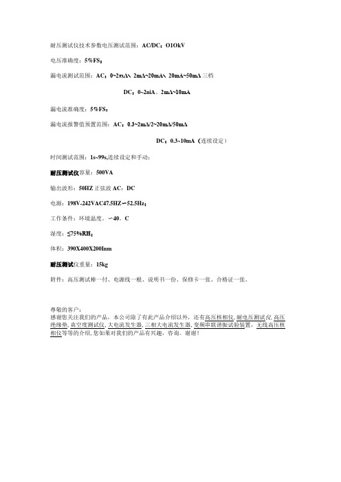
耐压测试仪技术参数电压测试范围:AC/DC:O1OkV
电压准确度:5%FS;
漏电流测试范围:AC:0~2πιΛ∖2mΛ~20mA∖20mA~50mΛ三档
DC:0~2niA、2mΛ~10mA
漏电流准确度:5%FS:
漏电流报警值预置范围:AC:0.3~2mΛ/2~20mΛ/50mΛ
DC:0.3~10mA(连续设定)
时间测试范围:1s~99s,连续设定和手动;
耐压测试仪容量:500VA
输出波形:50HZ正弦波AC:DC
电源:198V-242VAC47.5HZ〜52.5Hz;
工作条件:环境温度。
〜40。
C
湿度:≤75%RH;
体积:390X400X200Inm
耐压测试仪重量:15kg
附件:高压测试棒一付、电源线一根、说明书一份、保修卡一张、合格证一张。
尊敬的客户:
感谢您关注我们的产品,本公司除了有此产品介绍以外,还有高压核相仪,耐电压测试仪,高压绝缘垫,真空度测试仪,大电流发生器,三相大电流发生器,变频串联谐振试验装置,无线高压核相仪等等的介绍,您如果对我们的产品有兴趣,咨询。
谢谢!。
220kV长宁明德110kV工程记录表
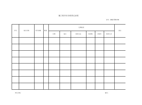
施工机具安全检查记录表表号:SAQ-TZh-018单位名称:编号:使用保管单位: 填写人: 填表日期:附件:施工质量验收及评定范围划分表计量器具台账产品检验记录项目部名称:220kV长宁变110kV配套送出工程(长宁变至明德变)表号: 编号:SZLX11-001注由施工项目部填报,施工项目部存 _份混凝土试块抗压强度汇总表工程名称:220kV长宁变110kV配套送出工程(长宁变至明德变) 编号:SZLX20-001施工项目技术负责人: 审核:混凝土试块抗压强度汇总表工程名称:220kV长宁变110kV配套送出工程(长宁变至明德变) 编号:SZLX20-002施工项目技术负责人: 审核:水泥跟踪管理记录工程名称:220kV 长宁变110kV 配套送出工程(长宁变至明德变)编制: 份。
审核:注 由施工项目部填报,施工项目部存年 月 日编号:SZLX22-001钢筋跟踪管理记录编号:SZLX22-002编制: 份。
审核:注 由施工项目部填才艮,施工项目部存工程名称:220kV 长宁变110kV 配套送出工程(长宁变至明德变)年 月 日同条件混凝土养护温度记录技术负责人: 日期:同条件混凝土养护温度记录工程名称:220kV长宁变110kV配套送出工程(长宁变至明德变)编号:SZLX19-002技术负责人:日期:SZLX27 工程质量问题处理单工程质量问题处理单工程概况表3.技术经济分析表[竣结-02 (Z)]主要技术经济分析表建设项目结算汇总表5. 工程结算费用汇总表[竣结-04 (Z)]工程结算费用汇总表6. 工程结算费用一览表[竣结-05 (Z)]工程结算费用一览表7. 合同价款费用汇总表[竣结-06 (F)]合同价款费用汇总表8. 工程变更费用明细表[竣结-07 (F)]工程变更费用明细表9. 建筑、安装、其他费用明细表[竣结-08 (F)]建筑、安装、其他费用明细表11.甲供材料明细表[竣结-10 (F)]甲供材料明细表SJSX5 图纸收发登记表图纸收发登记表工程名称:购置预算明细表(单价元以上)。
电能质量分仪技术参数对照表

电能质量分析仪技术参数对照表公司共立日置日置測定項目・記録項目型号KEW63103197电能质量分析仪3196电能质量分析仪外観電圧(測定レンジ)○(150/300/600/1000V)○(600V)○(60(仅CH4)/150/300/600V)電圧測定確度±0.3%rdg.±0.2%f.s.±0.3%rdg.±0.2%f.s.AC:±0.2%rdg.±0.1%f.sDC:±0.3%rdg.±0.4%f.s 电流○○○电流测试精确度±0.3%rdg.±0.2%f.s.+传感器精确度±0.3%rdg.±0.2%f.s.+传感器精确度±0.2%rdg.±0.1%f.s.+传感器精确度(传感器种类)12种8128(5A:φ24mm)、8141(1000mA:φ24mm)8127(100A:φ24mm)、8142(1000mA:φ40mm)8126(200A:φ40mm)、8143(1000mA:φ68mm)8125(500A:φ40mm)、8146(30A:φ24mm)8124(1000A:φ68mm)、8147(70A:φ40mm)8129(3000A)、8148(100A:φ68mm)7种9660(100Aφ15)9661(500Aφ46)9669(1000Aφ55)9667(5000A:自制φ254)9694(5Aφ15)9695-02(50Aφ15)9695-03(100Aφ15)5种9660(100Aφ15)9661(500Aφ46)9669(1000Aφ55)9667(5000Aφ254)9694(5Aφ15)频率(测试范围)○(40~70Hz)○(45~66Hz)○(42.5~69Hz)有功功率○○○电力测试精确度±0.3%rdg.±0.2%f.s+传感器精确度±0.3%rdg.±0.2%f.s+传感器精确度±0.2%rdg.±0.1%f.s+传感器精确度视在功率○○○有功电量○○○无功电量○○○功率○○○Class A+A2:2001+A3:2003 CLASS AEN61000-3-2:2000EN61000-3-3:1995+A1:2001+A2:2001CLASS AEN61000-3-2:2000EN61000-3-3:1995+A1:200 1安全规格(安全性)EN61010-1:2001CATⅢ600V汚染度2EN61010-1:2001CATⅢ600VCA TⅣ300V汚染度2EN61010-1:2001CATⅢ600V汚染度2可在1个画面中确认EN50160规定的电能质量的各项目的功能×其他充電電池(連続5時間):単三アルカリ電池充电电池(连续6小时):电池包定价(1欧元=120円)本体价格18万円本体价格46万円市场价软件KEW POWER PLUS2(付属)9624-50PQA分析软件6万円9624-50PQA分析软件6万円可选件测试线电源供给线测试线电源供给线9722:5500円电能质量分析仪技术参数对照表2公司日置横河FLUKE測定項目・記録項目型号3169电力质量分析仪CW240电力计FLUKE434/433外観電圧(測定レンジ)○(150/300/600V)○(150/300/600/1000V)○(1~1000V)電圧測定確度±0.2%rdg.±0.1%f.s.±0.2%rdg±0.1rng基准電圧の0.5%电流○○○电流测试精确度±0.2%rdg.±0.1%f.s.+传感器精确度(96030,31,33,36)±0.6%rdg ±0.4rng(96032,34,35)±1.0%rdg ±0.8rng±1%±5计数(传感器种类)7种9660(100Aφ15)7种i400s(400A)*4个(标准配置)测试线电源供给线9722:5500円测试线电源供给电能质量分析仪技术参数对照表3公司法国CA公司法国CA公司測定項目・記録項目型号CA8334电能质量分析仪CA8335电能质量分析仪外観電圧(測定レンジ)AC线电压:960VacAC相电压:480VacDC电压:680VdcAC线电压:2000VacAC相电压:1000VacDC电压:1000Vdc電圧測定確度AC: ±(0.5% ±2个字)DC: ±(1% ±0.2V)AC: ±(0.5% ±2个字)DC: ±(1% ±5个字)电流○ 三通道○ 四通道电流测试精确度依据各电流钳- MN93A:±(0.5%+2个字)- AmpFlex(>10A):±(0.5% +1A)- C193:±(0.5%+2个字0- PAC93:交流:±(0.5% +1A)直流:±(1.5%+1A)依据各电流钳- MN93A:±(0.5%+2个字)- AmpFlex(>10A):±(0.5% +1A)- C193:±(0.5%+2个字0- PAC93:交流:±(0.5% +1A)直流:±(1%+1A )(传感器种类)4种MN93A: 5mA-120Aac或MN93:2A~200AAmpFLEX A193(45cm/80cm):10A~6500AacC193:3~1200AacPAC9310~1000Aac4种MN93A: 5mA-120Aac或MN93:2A~200AAmpFLEX A193(45cm/80cm):10A~6500AacC193:3~1200AacPAC9310~1000Aac。
建筑电气 工程检测计量器具一览表

用于漏电保护器模拟漏电检测
7
示波钳表
GST688A
2239-7-007
2020年7月21日
用于设备运行起动检测
填表人:
年月日
项目专业质量检查员:
年月日
项目质量技术负责人:
年月日
建筑电气工程检测计量器具一览表
GD2302006
工程名称
三旧改造项目之新乐平中学建设工程
施工单位
深圳市建设(集团)有限公司
序号
计量器具名称
型号
检定合格证有效期
检测用途
1
接地电阻测试仪
ZC-8
E字第040305号
2019年9月12日
用于检测防雷电阻值
2
电阻检定仪
DQJ1221
225-7-004
2020年3月18日
用于检测防雷电阻值
3
兆欧表
ZC25B-3
12-0340
2019年12月26日
用于检测电线电缆绝缘
4
兆欧表
JD-1B
2255-7-004
2019年11月28日
用于检测电线电缆绝缘
5
万用表
MODEL MF47
2255-7-009
2021年4月20试仪
S402D
0728220
数显仪表多功能说明书-1

(c) 要确保输入电压,电流相对应,相序一致,方向一致;否则会出现数值和符号错误(功率 和电能).
绝 缘:信 号,电 源,输 出 端 子 对 壳 电 阻> 5 MΩ
耐 压,信 号 输 入,电 源,输 出 间> A C 2 K V
2 尺寸: S□:120*120*106mm 9S 9 □: 6*96*95mm
2 重量: S□:0.6KG
9S 0 □: .5KG
2. 安装与接线
2.1 仪表尺寸
安装尺寸:a×b 开孔尺寸:s×y 面板尺寸:l×h (单位mm)
可编程遥控/报警继电器输出 容量5A/250VAC 5A/30VDC 可编程报警电量,开关输入,模拟输入或者遥控方式 遥测开关输入测量,无源干结点输入 可编程关联报警输出
电量:0.5 频率:±0.1Hz 有 功 电 能 :0 . 5 S 无功电能:1 模 拟 输 入 :0 . 5 高清液晶显示
工作温度 1 :- 0-55ºC 储存温度 2 :- 0-75ºC
(通信校验位设置,修改后需重启) (遥控模式) (温湿度报警设置) (电测量报警设置)
(另三路报警设置类似)
(另三路变送设置类似)
操作说明: (a) 第三层菜单的数据(或选项)更改后,要按“ ”健退到第二层菜单,才能起效,如果按
3. 2 编程操作中按键的使用 四按键的常用功能: “ ”键和“ ” 键用于同层菜单的切换键或数值的加减;“MENU” 键用于菜 单上退或进入编程界面,“ ”为用于进入下层菜单或修改数值后的确认。 数显界面下如何实现个十百千位的增减: 个位数的增减:“ ”(按“ ”可以加数据0-9循环) 十位数的增减:进行十位数字量的增(减)时,可以按“ ”进行移位操作, 然后在按“ ”进行加大或减小 百位数的增减:进行百位数字量的增(减)时,可以按“ ”进行移位操作, 然后在按“ ”进行加大或减小 千位数的增减:进行千位数字量的增(减)时,可以按“ ”进行移位操作, 然后在按“ ”进行加大或减小 例如在菜单项目 INPT-PT-0001 下,若按“ ”会变成 INPT-PT-0002;若按 “ ”键可以对十位进行加减操作此时,若再按“ ”会变成 INPT-PT-0012; 若再按“ ”后可以对百位进行加减操作, 若再按“ ”键会变成 INPT-PT-0112,若再按“ ”可以对千位进行加减操作, 若再按“ ”键会变成 INPT-PT-1112. 3. 3 编程操作 3. 3. 1 菜单结构
电参数综合测量仪操作指导书
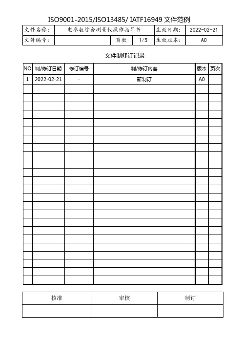
文件制修订记录1.0目的/Aim:1.1为电参数测量仪操作提供作业指导书,确保电参数测试仪对产品工作电压、电流、电能量、功率和功率因子的测量精度。
2.0参考文件/Reference Instruction:2.1电参数综合测量仪用户手册。
3.0设备/材料/ Equipment/Material:3.1 AN8720P电参数测试仪(需权威计量部门定期校验并在一定的期限范围内使用)。
4.0准备/要求/Prepare/Requirement:4.1 电源插座的下方放入保险丝,仪器接通电源, 确保输入电压为单相220伏,测试场所保持整齐、干净。
5.0安全/维护/Safety/Maintenance:5.1 使用本仪器之前,请认真阅读操作规程及使用说明书,并严格按规程操作,以免造成操作人员的人身伤害或仪器损坏。
5.2 测量过程中,请勿触摸测量仪后面板上的接线部分,谨防触电!5.3 拆接测量仪后面板上的接线时,请务必在切断电源后,再行操作!5.4 各输入输出端子连接部分应采取绝缘保护措施,以防止触电事故。
5.5 万一发生任何问题,请立即关闭电源。
5.6 不要让测量仪长时间超量程运行,测量仪允许的冲击信号幅值不要超过正常信号的1.6倍.测量仪不用时,请将仪表电源线拔下。
5.7 测量仪长期不用时,请包装保存在干燥、无粉尘、无强烈震动的环境下。
5.8 测量仪长时间保存后再次使用,使用前应开机30分钟后再测量使用。
6.0操作程序/Operation Process:6.1仪器参数设置6.1.1非锁定时,按“参数设置”按键即可进入参数设定状态.进入参数设定状态后,提示符“SET”点亮.每按一次“参数设置”按键会依次进入通讯地址、波特率、校验位、门限电流值显示单位的参数设定,相应提示符同时点亮.参数设定状态下,用“增/减”键可修改参数数值.第五次按下“参数设置”键,退出参数设定状态,提示符“SET”熄灭,设置值将被保存。
- 1、下载文档前请自行甄别文档内容的完整性,平台不提供额外的编辑、内容补充、找答案等附加服务。
- 2、"仅部分预览"的文档,不可在线预览部分如存在完整性等问题,可反馈申请退款(可完整预览的文档不适用该条件!)。
- 3、如文档侵犯您的权益,请联系客服反馈,我们会尽快为您处理(人工客服工作时间:9:00-18:30)。
Digital Power Meter ManualRead the manual carefully before use. Never let this instrument hit the ground. This is an accurate instrument. Never attempt to disassemble or remodel this instrument. Keep liquids away from this instrument. Wipe this instrument with a dry cloth to clean dust off. Wipe this instrument with damp cloth wrung almost dry when it is very dirty. Never use benzene, alcohol and thinner. Prevent foreign matter from getting into this instrument. Never install in places which are subject to direct sunlight, humidity, dust, water vapor or excessive heat. Use crimp-type terminals wiring to the terminal block. Take up the slack. Never input more than maximum voltage or current. The display disappears and the output stops at the power outage of the control power. Never touch the terminal block while power is on. Electrocution hazard. Be careful never to open the input line from CT secondary while power is on. Opening it causes high voltage at CT secondary and results in CT breakage. Never short the input line from VT secondary while power is on. Do not install communication or analogue output line on parallel with power or high voltage lines. When they cross them each other, take enough spacing. Any terminal of voltage input and load side terminals of current input must be connected to the ground. The manual includes optional function, which may explain the extra function, in some cases. The specification and the manual may change without notice for improvement.InstallationTerminal Block Size with cover1SourceAux.PowerSourceAux.PowerLoadLoadSourceAux.PowerSourceAux.PowerLoadLoad2 Pulse Outputs2 Alarm OutputsPulse Output 1 Pulse Output 2Alarm Output 1 Alarm Output 2Shorting Ter & RS+ connects the terminator internally. Aux.Power2Setting ProcedureTo enter the Setting Display, press [SET] and [+] at the same time in the Measuring Display.Press [DISPLAY] to return to the Measuring Display.S03-01 Analog Output 1 ItemItemS01-40 Backlight BrightnessParity/Stop bit(Modbus Output Only34Analog Outputs SettingsCommunication Settings (RS-485Analog Output 1ItemHow to set up Press [SET]. The value at the bottom blinks. Press [+] or [-] to set up the expected value. Press [SET].(The value at the bottom lights up.)RS-485 Communication Number From 000 to 250, with decimal How to Set up Press [SET]. 1st digit in the lower digit blinks. Press [+] or [-] to change the setting value. Press [SET]. 2nd digit in the lower digit blinks. Press [+] or [-] to change the setting value. Press [SET]. 3rd digit in the lower digit blinks. Press [+] or [-] to change the setting value. Press [SET] (The setting value in the lower digit lights up.) RS-485 Communication SpeedAnalog Output 2ItemHow to set up Press [SET]. The value at the bottom blinks. Press [+] or [-] to set up the expected value. Press [SET].(The value at the bottom lights up.)Analog Output 3ItemHow to set up Press [SET]. The value at the bottom blinks. Press [+] or [-] to set up the expected value. Press [SET].(The value at the bottom lights up.)How to set up Press [SET]. The value at the bottom blinks. Press [+] or [-] to set up the expected value. Press [SET].(The value at the bottom lights up.) Setting Value Disp. Speed 12 1200BPS 24 2400BPS 48 4800BPS 96 9600BPS 192 19200BPSAnalog Output 4ItemHow to set up Press [SET]. The value at the bottom blinks. Press [+] or [-] to set up the expected value. Press [SET].(The value at the bottom lights up.)Communication Settings (Modbus)Analog Output 1 Watt Span Configurable between 50% and 125% of the rating How to Set up st Press [SET]. 1 digit in the lower digit blinks. Press [+] or [-] to change the setting value. Press [SET]. 2nd digit in the lower digit blinks. Press [+] or [-] to change the setting value. Press [SET]. 3rd digit in the lower digit blinks. Press [+] or [-] to change the setting value. th Press [SET]. 4 digit in the lower digit blinks. Press [+] or [-] to change the setting value. Press [SET] (The setting value in the lower digit lights up.) Analog Output 1 Var Span Configurable between 50% and 125% of the rating How to Set up Press [SET]. 1st digit in the lower digit blinks. Press [+] or [-] to change the setting value. nd Press [SET]. 2 digit in the lower digit blinks. Press [+] or [-] to change the setting value. rd Press [SET]. 3 digit in the lower digit blinks. Press [+] or [-] to change the setting value. Press [SET]. 4th digit in the lower digit blinks. Press [+] or [-] to change the setting value. Press [SET] (The setting value in the lower digit lights up.)Modbus Communication Number From 000 to 250, with decimal How to Set up st Press [SET]. 1 digit in the lower digit blinks. Press [+] or [-] to change the setting value. nd Press [SET]. 2 digit in the lower digit blinks. Press [+] or [-] to change the setting value. Press [SET]. 3rd digit in the lower digit blinks. Press [+] or [-] to change the setting value. Press [SET] (The setting value in the lower digit lights up.) Modbus Communication SpeedHow to set up Press [SET]. The value at the bottom blinks. Press [+] or [-] to set up the expected value. Press [SET].(The value at the bottom lights up.) Setting Value Disp. Speed 12 1200BPS 24 2400BPS 48 4800BPS 96 9600BPS 192 19200BPSHow to set up Press [SET]. The value at the bottom blinks. Press [+] or [-] to set up the expected value. Press [SET].(The value at the bottom lights up.) Setting Value Disp. Parity/Stop Bit N-1 Nothing 1 E-1 Even 1 O-1 Odd 1 N-2 Nothing 2 E-2 Even 2 O-2 Odd 25Pulse Output SettingsAlarm Output SettingsPulse Output 1 Item How to set up Press [SET]. The value at the bottom blinks. Press [+] or [-] to set up the expected value. Press [SET].(The value at the bottom lights up.)Alarm Output 1 Item How to set up Press [SET]. The value at the bottom blinks. Press [+] or [-] to set up the expected value. Press [SET].(The value at the bottom lights up.)Pulse Output 1 Scale Factor Setting How to set up Press [SET]. The value at the bottom blinks. Press [+] or [-] to set up the expected value. Press [SET].(The value at the bottom lights up.) Scale Factor SettingAlarm Output 1Configurable from -100% to 100% of Rating with primary valueHow to set up Press [SET]. The value at the bottom blinks. Press [+] or [-] to set up the expected value. Press [SET].(The value at the bottom lights up.) Alarm Output 2 Item How to set up Press [SET]. The value at the bottom blinks. Press [+] or [-] to set up the expected value. Press [SET].(The value at the bottom lights up.)Alarm Output 2Configurable from -100% to 100% of Rating with primary valuePulse Output 2 Item How to set up Press [SET]. The value at the bottom blinks. Press [+] or [-] to set up the expected value. Press [SET].(The value at the bottom lights up.)How to set up Press [SET]. The value at the bottom blinks. Press [+] or [-] to set up the expected value. Press [SET].(The value at the bottom lights up.)Pulse Output 2 Scale Factor Setting How to set up Press [SET]. The value at the bottom blinks. Press [+] or [-] to set up the expected value. Press [SET].(The value at the bottom lights up.) Scale Factor SettingCautionThe scale factor of pulse output must be below 12000 pulse per hour. Otherwise, you may not measure correctly.6Setting Items at a glance7Note about Setting8Setting Code at a glance910Initialization about the setting valueInitializing the setting values also puts the other setting values into the default in page 7.Initializing the setting values also puts the measured maximum and minimum values into the default.Watt hour cannot be initialized.Please initialize after retained the present setting values.To enter the Phase Detection display, press [-] in the measuring display.Phase DetectionTo see the values which are not shown in the measuring display, press [ ].You can enter the detailed display. To return the measuring display, press[DISPLAY].See “XM2 Advanced Manual (Basic Operation)”.Digital Input DisplayThe manual is subject to change without notice in order to improve and be high quality.k_tanaka@takemotodenki.co.jpThe second edition on 2012.OCT.10. the first edition on 2012. JUN.21.。