空冷器使用维护说明书(英文)
空冷风机使用维护说明

技
3.2.安装准备 a) 清理主轴、锥套及轮毂的配合表面。 b) 检查主轴是否垂直。如果垂直误差超过 0.5°则必需加以校正 c) 确保主轴与风筒同轴,同轴度误差不大于 5mm。 3.3.安装步骤
在任何风机组装前,要确保电机不会被意外启动。切断电机电源并按如下 步骤安装: a) 将锥套(4)滑装到主轴(14)上。 b) 将轮毂板(1)及锥套座(3)(出厂前以组装好)安装到锥套(4)上。 c) 确保锥套(4)法兰边上的螺栓孔与锥套座(3)上的螺纹孔对齐。穿上螺 栓逐步拧紧,最终拧紧力矩 40-50N M。使轮毂抱紧在传动轴上。 4.叶片的安装: a) 将上压块(7)从轮毂上移开,将叶轴放入下压块(2)槽中。 b) 叶片前缘(厚边)必需朝向指定的旋转方向。 c) 扣上上压块(7)穿入 U 形螺栓(5)并安装垫圈(8)及锁紧螺母(9),手
目录
航
技
2 2 2 3 3 3 6 8 9 11 11 11 12
1
保定航技风机制造有限公司
BAODING HJ FAN MANUFACTURING CO., LTD.
航
技
一.总述
1.风机简介: 风机总成含叶轮及传动系统。叶轮由锻铝合金叶片碳钢轮毂两部分组成。
传动系统包括电机架、驱动带轮、从动带轮、上下轴承座、主轴及传动带。风 机的构架或基础均应有足够的强度、刚度和稳定性,能吸收和隔离振动,防止 发生共振。 2. 风机铭牌说明:
盘动主轴,主轴应转动自如,力度均匀。
e) 安装加油管至轴承座,见图 7。油管为铜管。安装时应清除管口毛刺及管内
4
保定航技风机制造有限公司
BAODING HJ FAN MANUFACTURING CO., LTD.
航
技
西屋空调使用手册-英文说明书

ENGLISHBefore operating the unit, read these operatinginstructions thoroughly and keep them for futurereference.Operating InstructionsAir Conditioner Model No.Indoor Unit Outdoor UnitCS-S9NKUA CU-S9NKUACS-S12NKUA CU-S12NKUAF568315© Panasonic Appliances Air-Conditioning Malaysia Sdn. Bhd. 2012. Unauthorized copying and distribution is a violation of law.2Thank you for purchasing Panasonic Air Conditioner TABLE OF CONTENTS SAFETY PRECAUTIONS2~3REMOTE CONTROL4~5INDOOR UNIT6TROUBLESHOOTING7INFORMATION8QUICK GUIDEBACK COVERNOTEThe illustrations in this manual are for explanation purposes only and may differ from the actual unit. They are subjected to change without notice for future improvement.SAFETY PRECAUTIONSTo prevent personal injury, injury to others, or property damage, please comply with the following.Incorrect operation due to failure to follow instructions below may cause harm or damage, the seriousness of which is classi fi ed as below:WARNINGThis sign warns of death orserious injury.CAUTIONThis sign warns of injury or damage to property.The instructions to be followed are classi fi ed by the following symbols:This symbol denotes an actionthat is PROHIBITED.These symbols denote an actions that is COMPULSORY.WARNINGINDOOR UNIT AND OUTDOOR UNITThis appliance is not intended for use by persons (including children) with reduced physical, sensory or mental capabilities, or lack of experience and knowledge, unless they have been given supervision or instruction concerning use of the appliance by a person responsible for their safety. Children should be supervised to ensure that they do not play with the appliance.Please consult authorized dealer or specialist to clean the internal parts, repair, install, remove and reinstall the unit. Improper installation and handling will cause leakage, electric shock or fi re.Con fi rm to authorized dealer or specialist on usage of speci fi ed refrigerant type. Using of refrigerant other than the speci fi ed type may cause product damage, burst and injury etc.Do not install the unit in a potentially explosive or fl ammable atmosphere. Failure to do so could result in fi re.Do not insert your fi ngers or other objects into the air conditioner indoor or outdoor unit, rotating parts may cause injury.Do not touch the outdoor unit during lightning, it may cause electric shock.Do not expose yourself directly to cold air for a long period to avoid excess cooling.Do not sit or step on the unit, you may fall down accidentally.Air InletAir OutletAir OutletAir InletOutdoor UnitPower SupplyRemoteControlOPERATION CONDITION Use this air conditioner under the following temperature range Temperature (°F)Indoor *DBT *WBT COOLINGMax.89.673.4Min.60.851.8Temperature (°F)Outdoor *DBT *WBT COOLINGMax.109.478.8Min.5.0-* DBT : Dry bulb temperature * WBT : Wet bulb temperature POWER SUPPLYModels NumberTime Delay Circuit Breaker Rated VoltsCS/CU-S9NKUA 15 Amps 208/230V CS/CU-S12NKUA 15 Amps Indoor Unit3CAUTIONINDOOR UNIT AND OUTDOOR UNITDo not wash the indoor unit with water, benzene, thinner or scouring powder to avoid damage or corrosion at the unit.Do not use for preservation of precise equipment, food, animals, plants, artwork or other objects. This may cause quality deterioration, etc.Do not use any combustible equipment in front of the air fl ow outlet to avoid fi re propagation.Do not expose plants or pet directly to air fl ow to avoid injury, etc.Do not touch the sharp aluminium fi n, sharp parts may cause injury.Do not switch ON the indoor unit when waxing the fl oor. After waxing, aerate the room properly before operating the unit.Do not install the unit in oily and smoky areas to prevent damage to the unit.Do not dismantle the unit for cleaning purpose to avoid injury.Do not step onto an unstable bench when cleaning the unit to avoid injury.Do not place a vase or water container on the unit. Water may enter the unit and degrade the insulation. This may cause an electric shock.Do not open window or door for long time during COOL/DRY mode operation.Ensure drainage pipe is connected properly and keep drainage outlet clear of gutters, containers or does not immersed in water to prevent water leakage.After a long period of use or use with anycombustible equipment, aerate the room regularly.After a long period of use, make sure theinstallation rack does not deteriorate to prevent the unit from falling down.REMOTE CONTROLDo not use rechargeable (Ni-Cd) batteries.It may damage the remote control.To prevent malfunction or damage of the remote control:• Remove the batteries if the unit is not going to be used for a long period of time.• New batteries of the same type must be inserted following the polarity stated.WARNINGREMOTE CONTROLDo not allow infants and small children to play with the remote control to prevent them from accidentally swallowing the batteries.POWER SUPPLYDo not use a modi fi ed cord, joint cord, extension cord or unspeci fi ed cord to prevent overheating and fi re.To prevent overheating, fi re or electric shock:• Do not share the same power outlet with other equipment.• Do not operate with wet hands.• Do not over bend the power supply cord.If the supply cord is damage, it must be replaced by the manufacturer, its service agent or similarly quali fi ed persons in order to avoid a hazard.It is strongly recommended to install this unit using an Earth Leakage Circuit Breaker (ELCB) or Ground Fault Interrupt (GFCI) or ApplianceLeakage Current Interrupt (ALCI) to prevent electric shock or fi re.Stop using the product if any abnormality/failure occurs or turn off the power switch and breaker.(Risk of smoke/fi re/electric shock)Examples of abnormality/failure• The ELCB or GFCI or ALCI trip frequently. • Burning smell is observed.• Abnormal noise or vibration of the unit is observed.• Water leaks from the indoor unit. • Power cord becomes abnormally hot.• Fan speed cannot be controlled.• The unit stops running immediately even if it is switched on for operation.• The fan does not stop even if the operation is stopped.Contact your local dealer immediately for maintenance or repair assistance.This equipment must be earthed to prevent electrical shock or fi re.Prevent electric shock by switching off the power:- Before cleaning or servicing.- Extended non-use.- Abnormally strong lightning activity.4REMOTE CONTROLMaximum distance: 26ftINDICATORPOWER (Green) TIMER (Orange) QUIET (Orange)POWERFUL (Orange)A U T O C O O L D R YF A N S P E E D A IR S W IN GF A N S PE E DA IR S WINGM O D EQ U IE T T E M PO F F /ONP O W E RF U LT IM E R S E TC A N CE LO NO F F123342RemoteControl display6571Press the remote control’s button 1TO TURN ON OR OFF THE UNIT• Please be aware of the OFF indication on the remote control display to prevent the unit from starting/stopping improperly.2TO SET TEMPERATURE• Selection range : 60°F ~ 86°F.• Operating the unit within the recommended temperature could induce energy saving.COOL mode : 78°F ~ 82°F.DRY mode : 2°F ~ 4°F lower than room temperature.3TO SELECT OPERATION MODEAUTO mode - For your convenience• During operation mode selection the power indicator blinks.• Unit selects operation mode every 10 minutes according to temperature setting and room temperature.COOL mode - To enjoy cool air• Use curtains to screen off sunlight and outdoor heat to reduce power consumption during cool mode.DRY mode - To dehumidify the environment• Unit operates at low fan speed to give a gentle cooling operation.4TO SELECT FAN SPEED (5 OPTIONS)FAN SPEED• For AUTO, the indoor fan speed is automatically adjusted according to the operation mode.5TO ADJUST VERTICAL AIRFLOW DIRECTION (5 OPTIONS)AIR SWING• Keeps the room ventilated.• In COOL/DRY mode, if AUTO is set, the louver swing up/down automatically.6TO ENJOY QUIET OPERATION• This operation reduces air fl ow noise.7TO REACH TEMPERATUREQUICKLY• This operation stops automatically after 20 minutes.891210118Press and hold for 5 seconds to dim or restore the unit’s indicator brightness.9Press and hold for approximately 10 seconds to show temperature setting in °C or °F10Press and hold for approximately 5 seconds to show 12-hour (am/pm) or 24-hour time indication.11Press to restore the remote control’s default setting. 12Not used in normal operations.NOTESQUIET,POWERFUL• Can be activated in all modes and can be cancelled by pressing the respective button again.QUIET,POWERFUL• Cannot be selected at the same time.TO SET THE TIMER• To turn ON or OFF the unit at a preset time.ONOFF12SETSelect ON orOFF timer Set the time Confi rm• To cancel ON or OFF timer, press ON or OFF then press CANCEL.• When ON Timer is set, the unit may start earlier (up to 15 minutes) before the actual set time in order to achieve the desired temperature on time.• Timer operation is based on the clock set in the remote control and repeats daily once set. For clock setting, please refer to Remote Control Preparation on the back cover.• If timer is cancelled manually or due to power failure, you can restore the previous setting (once power is resumed) by pressing SET.56CAUTION• Switch off the power at the circuit breaker before cleaning.• Do not touch the aluminium fi n, sharp parts may cause injury.CLEANING INSTRUCTIONSHINT• Do not use benzene, thinner or scouring powder.• Use only soap ( pH7) or neutral household detergent.• Do not use water hotter than 104°F.• To ensure optimal performance of the unit, cleaning maintenance has to be carried out at regular intervals. Dirty unit may cause malfunction and you may see error code “H99”. Please consult authorized dealer.INDOOR UNIT2567143981INDOOR UNIT • Wipe the unit gently with a soft, dry cloth.2FRONT PANELRemove Front Panel• Raise and pull to remove the front panel.• Wash gently and dry.Close Front Panel• Press down both ends of the front panel to close it securely.3REMOTE CONTROL RECEIVER 4ALUMINIUM FIN5HORIZONTAL AIRFLOW DIRECTION LOUVER• Manually adjustable.6VERTICAL AIRFLOW DIRECTION LOUVER• Do not adjust by hand.7AUTO OFF/ON BUTTON• Use when remote control is misplaced or a malfunction occurs.Step Action Mode 1Press once.Automatic2Press and hold until you hear one beep, then release.Force cooling3Repeat step 2. Press and hold until you hear two beeps, then release.Normal coolingPress the button to turn off.8AIR PURIFYING FILTERVacuum the air purifying fi lter.• It is recommended to clean the fi lter every 6 months.• Replace the fi lter every 3 years or replace any damaged fi lter.Part no.: CZ-SA20P 9AIR FILTERS• Air fi lter cleaning is required every two weeks.• Wash/rinse the fi lters gently with water to avoid damage to the fi lter surface.• Dry the fi lters thoroughly under shade, away from fi re or direct sunlight.• Replace any damaged fi lters.7The unit stops and the TIMER indicator e remote control to retrieve error code.TIMER SET CANCELON OFF 1231Press for 5seconds.3Press for 5 seconds to quit checking.2Press until you hear beep sound, then write down the error code.Note:• For certain errors, you may restart the unit for limited operation with 4 beeps when operation starts.4Turn the unit off and reveal the error code to authorized dealer.TROUBLESHOOTINGThe following symptoms do not indicate malfunction.SYMPTOMCAUSEMist emerges from indoor unit.►• Condensation effect due to cooling process.Water fl owing sound during operation.►• Refrigerant fl ow inside the unit.The room has a peculiar odor.►• This may be due to damp smell emitted by the wall,carpet, furniture or clothing.Indoor fan stops occasionally during automatic fan speed setting.►• This helps to remove the surrounding odours.Operation is delayed a few minutes after restarting.►• The delay is a protection to the unit’s compressor.Outdoor unit emits water/steam.►• Condensation or evaporation occurs on pipes.TIMER indicator is always on.►• The timer setting repeats daily once set.POWER indicator blinks before the unit is switched on.►• This is a preliminary step in preparation for the operation when the ON timer has been set.Cracking sound during operation.►• Changes of temperature caused the expansion/contraction of the unit.Check the following before calling for servicing.SYMPTOMCHECKCooling operation is not working ef fi ciently.►• Set the temperature correctly.• Close all doors and windows.• Clean or replace the fi lters.• Clear any obstruction at the air inlet and air outlet vents.Noisy during operation.►• Check if the unit has been installed at an incline.• Close the front panel properly.Remote control does not work.(Display is dim or transmission signal is weak.)►• Insert the batteries correctly.• Replace weak batteries.The unit does not work.►• Check if the circuit breaker is tripped.• Check if timers have been set.The unit does not receive the signal from the remote control.►• Make sure the receiver is not obstructed.• Certain fl uorescent lights may interfere with signal transmitter. Please consult authorized dealer.INFORMATIONFOR SEASONAL INSPECTION AFTER EXTENDED NON-USE• Check remote control batteries.• No obstruction at air inlet and air outlet vents.• Use Auto OFF/ON button to select Cooling operation. After 15 minutes of operation, it is normal to have the following temperature difference between air inlet and air outlet vents:Cooling: ≥ 14.4°FFOR EXTENDED NON-USE• Switch off power at the circuit breaker.• Remove the remote control batteries.NON SERVICEABLE CRITERIASSWITCH OFF POWER AT THE CIRCUIT BREAKER then please consult an authorized dealer under the following conditions:• Abnormal noise during operation.• Water/foreign particles have entered the remote control.• Water leaks from Indoor unit.• Circuit breaker switches off frequently.• Switches or buttons are not functioning properly.Information for Users on Collection and Disposal of Old Equipment and used Batteries[Information on Disposal in other Countries outside the European Union]These symbols are only valid in the European Union. If you wish to discard these items, please contact your local authorities or dealer and ask for the correct method of disposal.Note for the battery symbol (bottom twosymbol examples):This symbol might be used in combination witha chemical symbol. In this case it complies withthe requirement set by the Directive for thechemical involved.PbContact your local hazardous waste disposal hotline.Models Number CS-S9NKUA / CU-S9NKUA CS-S12NKUA / CU-S12NKUAThe above listed models have been designed and manufactured to meet ENERGY STAR® criteria forenergy effi ciency when matched with appropriate coil components. However, proper refrigerant chargeand proper air fl ow are critical to achieve rated capacity and effi ciency. Installation of this product shouldfollow the manufacturer’s refrigerant charging and airfl ow instructions. Failure to confi rm proper charge andairfl ow may reduce energy effi ciency and shorten equipment life.Federal Communications Commission Interference StatementThis device complies with part 15 of the FCC Rules. Operation is subject to the following two conditions: (1) This device may not cause harmful interference, and (2) this device must accept any interference received, including interference that may cause undesired operation.This equipment has been tested and found to comply with the limits for a Class B digital device, pursuant to part 15 of the FCC Rules. These limits are designed to provide reasonable protection against harmful interference in a residential installation. This equipment generates, uses and can radiate radio frequency energy and, if not installed and used inaccordance with the instructions, may cause harmful interference to radio communications. However, there is no guarantee that interference will not occur in a particular installation. If this equipment does cause harmful interference to radio or television reception, which can be determined by turning the equipment off and on, the user is encouraged to try to correct the interference by one or more of the following measures:• Reorient or relocate the receiving antenna.• Increase the separation between the equipment and the receiver.• Connect the equipment to an outlet on a circuit different from that to which the receiver is connected.• Consult the dealer or an experienced radio/TV technician for help.FCC Caution: To assure continued compliance, follow the attached installation instructions. Any changes or modifi cations not expressly approved by the party responsible for compliance could void the user’s authority to operate this equipment.Industry Canada NoticeThis Class B digital apparatus complies with Canadian ICES-003.8MEMOQUICK GUIDEAUTOCOOLDRYFANSPEEDAIRSWINGFAN SPEEDAIR SWINGMODEQUIETTEMPOFF/ONPOWERFULTIMERSETCANCELONOFF123213Remote Control Preparation123TIMERSETCANCELONOFF1234561Pull out2Insert AAA or R03 batteries (can be used ~ 1 year)3Close the cover4Press CLOCK5Set time6Confi rmMODEAUTODRY COOLSelect the desired mode.1OFF/ONStart/stop the operation.2TEMPSelect the desired temperature.3Printed in MalaysiaPanasonic CorporationWebsite: /For inquiries, please call 1-800-851-1235F568315SS1211-1。
松芝空调英文使用维护手册

Company profileShanghai Jialeng Songz Automobile Air-Condition Co. L TD (Hereinafter as SONGZ) invested by Hongkong Yi-fu-rong-xing Co. L TD of $30,000,000, is a single venture company sited in Shanghai Xinzhuang Industrial Development Zone. SONGZ focuses on R&D, manufacture and sales of automobile air conditioner with the brand name marked ‘SONGZ’ or ‘松芝’.With an area of 20,000 m2, located on No.4999, Huaning Rd., Shanghai Xinzhuang Industrial Development Zone, SONGZ has a complete A/C set of product machines and test devices, which represent the advanced level in China, including the domestic largest bus air conditioner bench test apparatus (With the cooling capacity of 40,000 Kcal/H).SONGZ has attracted lots of excellent automobile A/C engineers, thus owns a powerful R&D ability. It can design and offer high-quality products to satisfy the customers entirely according to their various demands for different buses.Our main products are bus roof-mounted air conditioners, including LUX/BBP/HLB/JLC series adopted in 7~14m long buses, SZA series (7~12m), and APP series (6~14m), bus inner-roof-combined-mounted series (6~14m).Dedication to the Improvement of Mankind’s Living-ConditionSONGZ Bus Air Conditioner—The Moving SpringCatalogue◇Preface 2◇Attention 3◇Product Introduction 4◇A/C Operation and Maintenance 7◇A/C Service 13◇A/C Trouble Analysis and Elimination 22◇The System of SONGZ Service Stations 29PrefacePlease read the handbook carefully to make sure using our products correctly.The context of the handbook is mainly about the operation, maintenance and service of SONGZ Roof-mounted Bus Air Conditioners.The information offered in this handbook may not complete. Please contact our customer service department or service station, and you’ll get a satisfied feedback.SONGZ Service Hot Line:0086-21-54422057◆Please give the handbook to the driver.◆Please refer to the common trouble information in the handbook and contact thecustomer service department or service station of SONGZ, when your bus air conditioner fails to work.◆Please keep the handbook properly in the bus so as to use it at any moment.◆The handbook is only for reference, and any modification would not be informed of.SONGZ sincerely appreciates your further advices and suggestions for our products and service.CHAPTER 1 ATTENTION1.1 Safety Pr ocee di ngs1)Shut off A/C power swi tch i mmediatel y when A/C alarms.2)Strictl y pr ohi bi t tou chi ng the r otati ng com ponent s (fan s, belts, pulleys, etc.) an d h ot par ts(com pre ssor, hi gh pre ssure h ose, et c.) of A/C, when A/C i s runni ng or power-off.3)A/C el ectri cal a ppl i ance are stri ctly pr ohi bi ted w orki ng with water on.4)Unpr ofe ssi onal te chni ci ans coul dn’t t ou ch A/C f or fea r tha t any a cci dent occur s.1.2 U se Comf orta bl y1)Please park the A/C bu s i n the cool and draughty place.2)Please cl ose bu s door s, wi ndow s an d the venti l ati on fa ciliti es when A/C i s running.3)Please mai ntai n A/C a ccor di ng t o ‘Mai ntenan ce C alenda r’ i n the han dbook.1.3 The Servi ce Rul e s f or Cu st omer s1)Please fi l l i n <<SONGZ Servi ce Tra ck Car d>> i n detail s an d mai l i t to the cu stomer servi cede partment of SON GZ i n or der to create cu stomer fi les on ce the bu s bei ng pur cha se d, so that your l egal ri ghts could be pr ote cte d.2)Please conta ct the cu st omer servi ce de partment or servi ce station of SON GZ, when y our bu s aircon di ti oner nee ds re pai r.3)We w oul d n ot take any re spon si bi li ty for the tr ou bles cau se d by impr oper in stall ation an d wr ongoperati on.W arnin g:The occurred troubles are not listed on the guarantee provisions if A/C is disassembled and maintained by yourself or non-SONGZ-engaged service agencies without permission, even though you have the guarantee card.Chapter 2 Product Introduction1.1 Summaryfigure good-looking.2)The interior components of A/C match well to make sure that the A/C systemcould get a higher refrigeration coefficient (COP).3)Choosing an appropriate fresh air device, which can provide 10~20% fresh airfrom outside to make the passengers comfortable.4)The use of the ozone-friendly refrigerant, HFC134a, can reduce the pollution toour environment to a maximal extent.5)The main components of A/C include a roof-mounted evaporator & condenserass’y, a compressor ass’y, hose &pipe (H&P) and a control panel. The evaporator & condenser ass’y is installed at the top of the bus.1.2 A/C Total Layout1.3 A/C technical parametersThe Chart of Basic types of SZA /BBP /JLC Series for SONGZ A/C Coach & TouringBusThe Chart of Basic types of APP/LUX/HLB Series for SONGZ A/C City BusNote:With the continuous improvement of the A/C products of SONGZ, some differences may exist in the Charts of Basic types above. We reserve the rights of non-announce in advance.CHAPTER 3 A/C Operation and Maintenance 3.1 A/C Operation3.1.1 The Functions of Control Panel1) The Operation Functions of Control PanelSwitches and the corresponding lights:[1] “On/ Off" touch button: < ━>- AC starts and vents,< ◈>- ACstops and ventilation is ceased.[2] “ Mode" touch button: <cool>---green light, air conditioner cools andvents; <vent>---green light, air conditioner vents; <auto>---green light, air conditioner vents and cools automatically.[3] “ fresh a ir" touch button: <on>---green light, fresh air valve opens andsystem starts to vent; <auto>---green light, opening of fresh air valve depends on the temperature setting for the carriage (in phase with cooling).[4] “temp" touch button: <setting>---green light, <carriage>---green light, <defrost>---green light.[5] “Digital Display": 3-digit, 8-section digital display (red) is used fortemperature indication.[6] “△" and “▽" touch buttons: Set the carriage temperature up anddown or “page through" the evaporator surface temperatures and failure types.[7] touch buttons: Adjust the air flow of the fan, “ green lightcolumn" indicates the air speed( as illustrated in the following figures).[8] “ Failure Light": Flashes red in case of any abnormal conditions, andcooling is stopped. Press “△ " or “▽ " button at this time, the digital display will show the failure code: “ EP1" or “ EP2" means abnormal air conditioning system pressure; “ EII1" means circuit break of the temperature sensor at the return air grille; “ EII2" and “ EII3" means circuit break of defrost sensor 1 or 2.[9] “ Undervoltage light": Flashe s red when the voltage is under a normal value, and stops cooling.3.1.2 Control Panel with heat function[1] Switches and the corresponding lights:“ Mode" touch button: <cool>---green light, air conditioner cools and vents;<vent / heat>---green light, air conditioner vents; <vent / heat>---green light sparkling, air conditioner vents;open the heat function;<auto>---green light, air conditioner vents and cools automatically.[2]Protect of heat function:While heating,when the tempreture of defrost sensor upper than 85℃,Automatically turns off the heat valve,low than 80℃,turns on automatically。
约克制冷机组说明书英文

约克制冷机组说明书英文York chiller units are a type of air conditioning system designed to provide efficient and reliable cooling for a wide range of commercial and industrial applications. These units are known for their advanced features, energy-efficient performance, and ease of installation and maintenance. In this essay, we will provide a comprehensive overview of the key components, operating principles, and maintenance requirements of York chiller units.At the heart of a York chiller unit is the compressor, which is responsible for circulating the refrigerant throughout the system. York chiller units typically employ either scroll or screw compressors, both of which are known for their high efficiency and reliability. The scroll compressor, for example, utilizes a pair of spiral-shaped scrolls that interlock and rotate to compress the refrigerant, while the screw compressor uses a pair of helical rotors to achieve the same result. These compressors are designed to operate at high speeds, allowing for a more compact and efficient overall system.The condenser is another critical component of a York chiller unit.This component is responsible for removing the heat absorbed by the refrigerant during the cooling process. York chiller units can be equipped with either air-cooled or water-cooled condensers, depending on the specific requirements of the application. Air-cooled condensers use fans to circulate air over the coils, while water-cooled condensers utilize a cooling tower or other water source to dissipate the heat.The evaporator is the component where the actual cooling process takes place. In a York chiller unit, the evaporator is typically a shell-and-tube or plate-and-frame heat exchanger, where the refrigerant absorbs heat from the water or air being cooled. This heat transfer process causes the refrigerant to vaporize, and the resulting vapor is then drawn back into the compressor to continue the cooling cycle.In addition to the compressor, condenser, and evaporator, York chiller units also incorporate a variety of other components, such as expansion valves, filters, and control systems. The expansion valve, for example, is responsible for regulating the flow of refrigerant into the evaporator, ensuring that the proper pressure and temperature conditions are maintained. Filters are used to remove impurities from the refrigerant, helping to maintain the system's efficiency and prevent damage to critical components.The control system of a York chiller unit is designed to optimize theunit's performance and ensure its safe and reliable operation. This system typically includes a microprocessor-based controller that monitors and adjusts various parameters, such as temperature, pressure, and flow rates, to maintain the desired cooling output. The control system may also include features like automatic restart, fault detection, and remote monitoring capabilities, allowing for easy troubleshooting and maintenance.One of the key advantages of York chiller units is their energy efficiency. These units are designed to minimize energy consumption through the use of advanced compressor technologies, efficient heat exchangers, and sophisticated control systems. Many York chiller units also incorporate features like variable-speed drives, which can adjust the compressor speed to match the cooling demand, further improving energy efficiency.Maintenance is an important aspect of ensuring the long-term performance and reliability of York chiller units. Regular inspection and servicing of the unit's components, such as the compressor, condenser, and evaporator, are essential to maintaining optimal efficiency and preventing breakdowns. York chiller units also require periodic cleaning of the condenser coils and evaporator coils to ensure proper heat transfer and maintain the system's cooling capacity.In addition to routine maintenance, York chiller units may also require occasional repairs or replacements of components. This can include tasks such as replacing worn-out seals, recharging the refrigerant, or addressing issues with the control system. It is important to follow the manufacturer's recommended maintenance and repair procedures to ensure the safety and reliability of the unit.Overall, York chiller units are a highly versatile and efficient cooling solution for a wide range of commercial and industrial applications. Their advanced design, energy-efficient performance, and ease of maintenance make them a popular choice among building owners, facility managers, and HVAC professionals. By understanding the key components, operating principles, and maintenance requirements of York chiller units, users can ensure that their cooling systems continue to operate at peak performance for years to come.。
Panasonic空調器操作說明書说明书
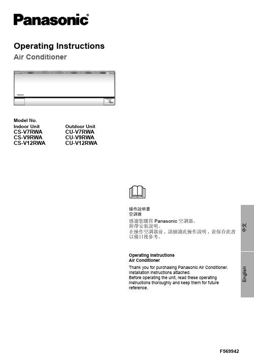
Model No.Indoor UnitOutdoor UnitCS-V7RWA CS-V9RWA CS-V12RWA CU-V7RWA CU-V9RWA CU-V12RWAOperating InstructionsAir Conditioner操作說明書空調器感謝您購買Panasonic 空調器。
附帶安裝說明。
在操作空調器前,請細讀此操作說明,並保存此書以備日後參考。
Operating Instructions Air ConditionerThank you for purchasing Panasonic Air Conditioner.Installation instructions attached.Before operating the unit, read these operating instructions thoroughly and keep them for futurereference.安全措施 ....................................................4-5如何使用 ....................................................6-7清洗說明 .......................................................8故障檢修 .......................................................9信息 .........................................................封底附件• 遙控器• AAA 或 R03 電池 × 2• 遙控器托架• 用於遙控器托架的螺釘 × 2Table of contentsSafety precautions .................................10-11How to use.............................................12-13Cleaning instructions ..................................14Troubleshooting .........................................15Information...................................Back coverAccessories• Remote control• AAA or R03 batteries × 2• Remote control holder• Screws for remote control holder × 2安全措施為了防止個人傷害,危害其他人或財物的損失,請遵守以下指示:因不遵守以下指示導致的錯誤操作將引起傷害或損壞,其嚴重程度分類如下:要遵守的指示按下列符號分類:室内機及室外機此裝置不適合殘疾、感應欠佳或智障,經驗與知識不足的人士(包括兒童)使用。
空冷器使用维护说明书

拆卸固定式空冷器时要按下列程序进行: 1. 排干冷却水 2. 用适当的升降装置支撑住空冷器 3. 拆开进出水管 4. 拆开气侧连接风罩,卸下空冷器。 安装时要使用如前所述新垫片。
拧紧力矩(Nm)
使 用 维 护 说 明 书 Operation And Maintenance Manual
从箱体里抽出来。 为了使管组比较容易地从箱体内抽出,我们固定
管板上钻有拆卸螺纹孔(孔径与箱体框架上的螺栓孔 相同),该螺纹孔用于起吊和拆卸时安装吊耳或拆卸螺 栓。 重新安装时应使用如前所述新密封垫。
4. 试运行 4.1 概 述
侧板上也焊有起吊耳。
将空冷器箱体安装进风道之前,可先将管组拆
下来。拆卸方法是:拧下把固定管板与箱体联接的螺
栓,并拆下密封填料或活动管板上的盖板。在管组的
固定端的端盖上钻有螺纹孔,该螺纹孔用于起吊和
拆卸时安装吊耳或拆卸螺栓的。
箱体安装好后,用螺栓把管组的固定管板紧固
到箱体上(加装新垫片),再安装密封填料或罩盖。
适用于标准公制螺纹、强度等级为8.8级的镀锌 螺栓。螺纹、螺栓和ห้องสมุดไป่ตู้帽的接触面上抹油
规格
M8 M10 M12 M14 M16 M18 M20
不用密封或 KLINGERSIL
密封垫 21 42 73 115 180 256 360
不用密封 或KLINGERSL密封垫
用 NORD- 防松垫圈
25 51 87 138 216 307 432
9、 Tube leaks Ge ner al Pressure test of individual tubes Pressure test of cooler Pressure test with air under water Plugging of tubes Replacement of single tubes (partial re-tubing) Insertion of a second core tube Pressure test after repair
Star Cool 冷機 使用手冊说明书
版本 810906C 2021年5月型號 SCI-20/40/CA 和 SCU-20/40112頁中的1頁1. 前言此版手冊發佈於2021年5月, 由馬士基集裝箱工業公司編輯. 版權所有.此用戶手冊是針對軟件版本0357或更高版本發佈的.此手冊資訊如有變更, 恕不另行通知,亦不代表馬士基集裝箱工業公司任何部門的承諾. 然而此手冊的資訊被認為是正確的, 馬士基集裝箱工業公司對其中的任何錯誤或遺漏不承擔責任.此手冊對如下有效:型號SCI - 20/40/CA and SCU - 20/40軟體版本03572. 警告如果您還沒有熟讀此手冊指導, 沒有完全弄懂此設備和操作,請不要操作或維修此製冷機組.在沒有斷開電源插頭之前請不要對機組動焊. 而且, 還需要斷開電源偵測模組與主控制器(如果安裝了貓也需要斷開).在檢查電控箱內部時請斷開機組的主供電電源.機組充注了R134a或R513A製冷劑和BSE 55型號的酯類潤滑油. 不要使用任何其它型號的製冷劑或潤滑油. 不要使用污染的製冷劑或潤滑油. 永遠不要向大氣中直接排放製冷劑. 請根據當地法律使用資源回收裝置.在維修過程中, 請注意製冷劑工作時, 產生高溫和低溫並伴有高壓的, 如果處理不當可能會造成人員受傷.在回收和製冷系統維修過程中, 個人防護用品必須穿戴齊全.在釺焊時要確保銅管內無殘留的液體製冷劑. 這可能會導致銅管爆炸.請注意一些型號的機組的吸氣壓力感測器(Psuc)和排氣壓力感測器(Pdis)沒有安裝閥針.我們不建議用PH值低於7的肥皂/洗滌劑來清洗冷藏箱內. 然而,如果這已經發生了, 請使用 PH值介於 7 到 9 之間的洗滌劑透過馬達檢查視窗來清洗蒸發器盤管. 這步清洗對減少蒸發器盤管腐蝕的風險至關重要.當箱內氧氣含量低於20.9%時不要進入箱內,也不要打開馬達服務蓋板. 無論是維修機組還是拆貨, 進入之前請務必進行通風. 通風時要遠離門端.人體對低氧環境的反應:112頁中的2頁3. 內容1. 前言 (1)2. 警告 (1)3. 內容 (2)4. 職權範圍 (6)5. 總覽 (8)6. 功能描述 (9)6.1 啟動過程 (9)6.2 溫度控制 (9)6.3 容量控制和限制器 (9)6.4 電路控制 (11)6.5 膨脹閥.... (11)6.6 經濟器閥 (11)6.7 除濕........ (11)6.8 冷凝風扇 (12)6.9 蒸發風扇 (12)6.10 化霜功能 (13)6.11 警報回應系統 (13)6.12 資料記錄 (13)7. 測試 (16)7.1 功能測試 (16)7.2長PTI (17)7.3 短PTI (17)7.4 氣調 PTI (17)8. 製冷系統資料 (18)8.1 製冷劑充注 (18)8.2 規範總覽 (18)8.3 壓縮機 – 馬達組件 (18)8.4 變頻器 (FC) (18)8.5 蒸發器盤管 (18)8.6 蒸發器盤管加熱器 (18)8.7 蒸發器風扇 (19)8.8 蒸發器風扇馬達 (19)8.9 冷凝器盤管 (19)8.10 冷凝器風扇 (19)8.11 冷凝器風扇馬達 (20)8.12 水冷冷凝器 (可選的) (20)8.13 新風交換 (20)8.14 新風交換馬達 (20)8.15 經濟器 (21)8.16 製冷控制 (21)8.17 真空泵, 包含泵加熱器 (21)8.18 電氣參數 (21)8.19 斷路器 (21)8.20 接觸器 (21)8.21 高壓切斷開關 (21)8.22 易熔塞, 儲液罐 (22)8.23 保險絲 (22)8.24 電纜插頭 (22)8.25 電纜線 (22)8.26 USDA插口規範 (22)112頁中的3頁8.27 O2 感測器 (22)8.28 CO2 感測器 (22)8.29 溫度感測器, 包括 USDA (23)8.30 濕度傳感器 (23)8.31 CA 壓力感測器 (23)8.32 壓力感測器 (23)8.33 其它項 (23)9. 使用者介面 (24)9.1 指示燈 (24)9.2 顯示幕 (24)9.3 按鍵板 (25)10. 菜單綜述 (26)10.1 頁面總體佈局 (26)10.2 使用游標 (27)10.3 改變參數 (27)10.4 啟動一個功能 (27)10.5 新風交換介面 (27)11. 操作 (28)11.1 功能表結構 (28)11.2 操作總覽 (29)11.3 溫度設置 (29)11.4 喚醒模式 (29)11.5 顯示幕對比度調節 (29)11.6 溫度單位轉換 (29)11.7 查看溫度曲線 (29)11.8 水冷開啟/關閉 (30)11.9 PTI 或功能測試 (30)11.10 資訊功能表 (33)11.11 原始感測器數值 (37)11.12 操作功能表設定 (38)11.13 程式 (39)11.13.1 多設定溫度程式, MTS (39)11.13.2 自動冷處理, ACT (40)11.13.3 鮮花模式 (42)11.14 應用設置 (43)11.14.1 AV/AV+ (43)11.14.2 CA......... .. (43)11.15 手動化霜 (45)11.16 警報 (45)11.17 服務功能設置 (46)11.18 手動運行 (47)11.18.1 變頻器自檢 (48)11.19 數據查看 (49)11.20 時間調整 (49)11.21 執行時間計數器 (50)11.22 配置.... (51)11.22.1 StarConomy 節能模式 (52)11.23 系列號 (53)11.24 USB菜單.... .. (54)11.25 維護保養 (55)11.26 數據機 (55)12. 外接介面 (55)12.1 基本要求 (56)12.2 外接介面術語清單 (56)12.3 功能總覽 (56)112頁中的4頁13. 事件 (57)14. 詳細警報描述 (60)14.1 警報列表 (60)15. Star Cool 機組安裝尺寸 (65)16. 馬達, 溫度感測器, 濕度感測器和新風交換感測器的位置 (66)17. 閥的位置 (67)18. 馬達, 溫度感測器, 濕度感測器和新風交換感測器的位置 (68)19. 電控箱示意圖 (69)20. AV和CA部件位置 (70)21. 更換 (73)21.1 更換蒸發器馬達和風扇 (73)21.2 更換冷凝器馬達和風扇 (73)21.3 更換蒸發器盤管 (74)21.4 更換蒸發器加熱器 (75)21.5 更換變頻器 (76)21.6 更換壓縮機 (77)21.7 更換壓縮機閥板/缸頭墊片 (78)21.8 更換乾燥篩檢程式 (79)22. 維護和維修 (79)22.1 回收製冷劑 (79)22.2 壓縮機排空和操作 (80)22.3 壓縮機排空(更換後) (80)22.4 回收和抽空 (81)22.5 試壓 (81)22.6 充注製冷劑 (82)22.6.1 空機組充注 (82)22.6.2 已有部分製冷劑充注 (82)22.7 檢漏 (83)22.8 壓縮機 (83)22.8.1 檢查油位 (83)22.8.2 壓縮機泄油 (83)22.8.3 加注壓縮機油 (84)22.9 釺焊 (84)22.9.1 電焊 (85)22.10 校驗新風交換感測器 (85)22.11 通過StarView校驗溫度感測器 (85)23. CA服務和故障排除 (85)23.1 集裝箱通風流程 (85)23.2 更換真空泵油過濾器和油 (86)23.3 真空系統故障診斷 (88)23.4 更換真空泵加熱器 (89)23.5 CA 裝貨準備 (89)23.6 門帘固定膠條安裝 (89)23.7 門帘安裝 (90)23.8 CA箱氣密檢測 (91)23.9 CA+ 充氣 (91)112頁中的5頁24. 故障診斷總則 (93)25. 應急操作 (93)25.1 FC 變頻器旁通 (93)25.1.1 FC 1.0 和 FC 1.1 (93)25.1.2 FC 2.0 (94)25.2 控制器旁通 (94)25.3 蒸發器馬達旁通 (94)26. 表格 (95)26.1 資料描述 (95)26.2 溫度感測器 - 電阻表 (97)26.3 溫度感測器 - 電壓表 (98)26.4 新風感測器 電壓 - m3/h表 針對35 CMH (99)26.5 新風感測器 電壓 - m3/h表 針對75 CMH (99)26.6 電壓 - 壓力錶, 低壓壓力感測器(NSK) + DST (100)26.7 電壓 - 壓力錶, 低壓壓力感測器 (AKS (101)26.8 電壓 - 壓力錶, 高壓壓力感測器(NSK) + DST (102)26.9 電壓 - 壓力錶, 高壓壓力感測器 (AKS) (103)26.10 壓力 - 溫度錶 R134a (104)26.11 壓力 - 溫度錶 R513A (104)26.12 扭矩要求 (105)27 圖表 (106)27.1 P & I diagram (106)27.2 CA 功能總覽 - 兩個版本 (107)28. 電路接線圖 - 帶子控制器的 CIM 6.0 (109)29. 電路接線圖 - CIM 6.1 (110)30. 電路接線圖 - CIM 6.2 (111)31. 電路接線圖 - 帶子控制器的 CIM 6.2 (112)112頁中的6頁4. 職權範圍112頁中的7頁112頁中的8頁5. 總覽冷星STAR COOL冷機, 機型號為SCU-40 和 SCI-40,是基於製冷劑R134a或R513A在通電後能夠進行製冷和加熱的機組.此機組的設計保持貨物溫度範圍是 -30°C (-22°F) to +30°C (+86°F). 此機組的設計適用環境溫度範圍是 -30°C (-22°F) to +50°C (+122°F).機組前外框是由海運等級的鋁材料製成的, 5000 和 6000 系列, 被設計成完全可以用來做為集裝箱的端壁. 機組的後背板是由可以接觸食品的材料做成的.機組是以完全適用於海運環境來設計的並做如下規範:• 含鹽霧空氣, 海浪飛沫, 和高濕度.• 橫搖: 每面30° 振幅, 週期13秒.• 縱搖: 每面6° 振幅, 週期8秒.• 永久傾斜: 每面15°.• 衝擊: 橫向2g,縱向 5g.• 振動: 在船上, 卡車上, 和鐵路上可能遇見的各式振動.機組包含如下模組:• 框架模組• 冷凝器/壓縮機模組• 蒸發器模組• 蒸發器風扇模組機組的製冷系統配備了一個雙級壓縮機, 並通過一個變頻器進行驅動.此製冷系統也配備了一個經濟器, 它用來對從儲液罐到蒸發器的液體製冷劑進行過冷, 從而增加機組的製冷量.蒸發器和經濟器是由電子膨脹閥來進行控制的.此設備根據ISO 1496-2設計的供電電源為3相初級電源:50 Hz (+/- 2.5), 360-460 V AC (最高 465 V AC) 或 60 Hz (+/- 2.5), 400-500 V AC (最高 535 V AC). 控制電壓是由一個一體式的雙繞組變壓器提供的. 一個繞組輸出電壓18.6-32.0 V AC (供給RMM貓), 另外一組電壓輸出為20.5-35.7 V AC並在控制器裡轉換成直流電壓(給控制器和接觸器). 輸出電壓取決於輸入電壓. 一個自動的電源檢測和修正系統, 可以確保風扇馬達的正確轉向.這跟主電源的相序沒有關係, 但要確保所有的風扇馬達的接線是正確的.一個可選配的水冷冷凝器安裝在風冷冷凝器下端. 水冷冷凝器可以允許機組在甲板下方運行, 那裡沒有通風, 要確保外接水冷系統接通.機組為底部送風, 頂部回風回到蒸發器盤管上方 (底部送風).機組具有完全電腦化控制的自動除濕功能. 除濕設定範圍是 95 – 65% RH (或關閉新風以達到低至 50%的設定). 機組可以控制到最低值. 只有當控制溫度進入設定溫度範圍後除濕功能才能啟動. 機組裝配有加熱器, 安裝在蒸發器盤管下面, 用來進行除濕. 在經濟Economy模式下除濕功能也能啟動.機組配有雙化霜系統.系統配有一個熱氣閥, 用熱氣來輔助蒸發器盤管化霜. 而且,安裝在蒸發器盤管下面的加熱器在除霜時也會啟動. 雙化霜系統可以確保快速的完成化霜從而減少因為化霜產生的熱量對箱內溫度的影響. 雙化霜系統也能夠保證熱量均勻的分配到蒸發器盤管各個角落. 這可以防止蒸發器局部的冰不能被順利融掉. 雙化霜系統,熱氣和加熱器, 是獨立的. 這可以確保隨時都能開啟化霜過程. 嵌入到軟體裡的自動化霜系統可以確保蒸發器盤管上不會被冰封住.電子控制器是由Bitzer Electronics製造的, 在保鮮模式下控制供風溫度 (設定溫度大於等於 -5°C (+23°F), 在冷凍模式下控制回風溫度 (設定溫度小於 -5°C (+23°F). 控制器精度 ±0.25°C (±0.45°F). 機組控制蒸發器風扇以低速和高速運行.通過控制器操作介面, 中可以選擇普通模式Normal或經濟模式Economy. 在經濟模式Economy下蒸發器風扇一直低速轉. 在普通模式Normal下蒸發器風扇以高速或低速運轉, 取決於保鮮還是冷凍模式.機組配有資料記錄儀, 其嵌入到控制器裡了. 資料記錄時間間隔是預設好的, 可以選擇15, 30, 60, 120, 或 240 分鐘. USDA 感測器 (3 根) 和cargo貨物溫度感測器的資料記錄時間間隔是1小時, 這是根據USDA 的要求做的設置. 以1小時做為資料記錄時間間隔算, 資料存儲可以達到365天. 資料記錄的精度為 ±0.25°C (±0.45°F). 資料可通過電腦端 (Star-view)和Psion Logman從機組的高速串口處進行提取. 也可以通過手機APP和Star Cool Dongle (藍牙適配器)來進行提取.機組配有備用電池, 在機組斷電後可以繼續記錄資料120次. 對CIM 6, 電池是可充電的. 對CIM 5, 電池是不可充電的.根據ISO 標準 10368, 控制器可以和遠端監控設備進行通訊. 事件events, 警報alarms, 和資料datalogs可以通過各種諸如Refcon, Logman, StarView等各種系統進行下載.112頁中的9頁6. 功能描述6.1 啟動步驟啟動分為5步:1. 初始化: 控制器自檢.2. 穩定化: 蒸發器風扇高速運行以確保箱內的溫度感測器測量的是當前溫度.3. 曲軸箱加熱: 如果Tamb環境溫度低於2°C (36°F) 變頻器會加熱壓縮機線圈直到Tfc變頻器溫度超過12°C (54°F).4. 暖機.5. 結束: 切換到正常的溫度和參數控制模式.6.2 溫度控制溫度控制功能已經潛入到了控制器的系統中.這個功能有兩種模式:1. 保鮮如果設定溫度Tset大於或等於-5°C (+23°F) 則進入到保鮮模式.如果是製冷狀態則實際控制溫度Tact = Tsup供風溫度, 如果是加熱狀態則實際控制溫度Tact = Tret 回風溫度. 2. 冷凍如果設定溫度Tset小於 -5°C (+23°F) 則進入到冷凍模式並且實際控制溫度Tact = Tret 回風溫度.保鮮和冷凍模式的分界溫度取決於軟體版本和客戶要求.溫度控制是進入到下來或加熱模式取決於實際溫度Tact是高於還是低於設定溫度Tset. 只要是實際溫度未進入到設定溫度Tset ± 1.5°C範圍內, 這個功能就會保持下來或加熱模式. 如果實際溫度進入到溫度範圍內, 這個綠色的IN-RANGE 範圍內指示燈就會開始閃爍. 當實際溫度進入到設定溫度Tset ± 1.5°C 範圍內超過30分鐘, 則綠色的溫度範圍內指示燈IN-RANGE就會變成常亮.如果實際溫度超出溫度範圍超過2小時, 溫度範圍內指示燈IN-RANGE將會開始閃爍. 實際溫度超出溫度範圍超過4小時之後, 將會產生一個超出溫度範圍的警報. 根據實際溫度Tact和設定溫度Tset等輸入參數這個功能會通過控制器計算需求的容量. 需求的容量CapReq是指想要取得的製冷/加熱容量. 需求的容量CapReq數值範圍是從–100% 到 +100%.–100%是指最大的製冷量, +100%是指最大的加熱量.保鮮模式冷凍模式6.3 容量控制和限制器根據需要的容量, 此功能判斷運行模式並控制各個系統部件(壓縮機, 閥, 加熱器) 以確保取得壓縮機最少的停機時間. 此功能有5個檔位元 (模式). 根據需要的容量, 來決定進入哪個檔位.壓縮機頻率是由當前模式直接決定的. 蒸發器加熱器, 不同的是, 它的檔位是獨立的. 模式切換是有一個過程的,為了保持各個模式之間平穩過渡.機組的容量控制在最大的製冷量 (-100% capacity) 和最大的加熱量 (+100% capacity) 之間. 這是通過變頻器調節壓縮機轉速或對壓縮機進行開/關調節. 在最大的加熱量 (+100% capacity) 內機組使用加熱器加熱, 進入到容量範圍後會對加熱器進行脈衝調節來控制加熱量.下圖顯示了容量範圍.System CapacityHeating %如果任何一個限制器被觸發, 壓縮機轉速將會降低從而使機組容量降低. 當一個限制器變為活躍後, 它將會在顯示幕主頁上狀態列裡顯示出來. 限制器的類型可以在資訊功能表 , 行I40可以看到.限制器類型:• TC冷凝溫度, 最大的冷凝壓力 (和溫度) 通常出現在溫度下拉的時候. 如果此機組和其它的Star Cool機組比較起來製冷量低, 清潔冷凝器盤管, 檢查排氣壓力Pdis, 檢查冷凝器馬達的功能和轉向.• IFC變頻器電流, 變頻器FC 最高的限電流.它出現的典型條件是在溫度下拉過程中尤其是環境溫度高於25°C (77°F).如果此機組跟其它的Star Cool 機組比較起來製冷量明顯較低, 請參考警報AL 511進行故障診斷尤其是注意檢查製冷劑液位 (是否過量充注).• TFC變頻器溫度, 變頻器FC的最高溫度. 它出現的典型條件是在溫度下拉過程中尤其是環境溫度高於40°C (104°F).如果此機組跟其它的Star Cool 機組比較起來製冷量明顯較低, 請參考警報AL 511進行故障診斷.• T0蒸發溫度, 最低的蒸發壓力很少被啟動. 如果這個限制器活躍超過2分鐘, 檢查製冷劑液位 (充注不足), 檢查吸氣壓力Psuc和吸氣溫度Tsuc, 檢查膨脹閥Vexp和低壓閥板.• ITOT, 通過降低壓縮機轉速來控制機組的總電流在範圍內. 它通常會在拉溫時尤其是環境溫度高於40°C (104°F)時出現. 當總電流達到13.5 A後壓縮機允許上升的頻率會分佈降低, 當總電流達到17.5 A時壓縮機頻率會被最大程度的降低以避免出現警報AL 421從而造成機組停機甚至出現斷路器跳閘的情況.多個限制器可能同時變成活躍. 多個限制器參數會被迴圈顯示. 最緊急的參數會被用來控制容量. 如果限制參數高於需要的容量變化, 容量實際會降低而不會增加. 比如當環境溫度很高時, 需求的容量會要求提升變頻器FC 的溫度, 當變頻器溫度超限時, 限制器會降低容量直到進入到一個對變頻器安全並穩定的運行狀態.6.5 膨脹閥此功能確保蒸發器過熱度(SH)為最優並計算和控制膨脹閥的開度(SHVod). 此功能只有在壓縮機工作時才生效. 壓縮機停機時膨脹閥是關閉的. 膨脹閥功能吧包含三個子功能:1. MSS (Minimum Stable Superheat search)最小穩定過熱度搜尋此功能在最小過熱度SHmin和最大過熱度SHmax之間搜尋最小的穩定過熱度. SHact: = Tsuc - T0 (Psuc)2. 過熱控制功能結果是控制膨脹閥 (Vexp)的開度. 在啟動過程中開度是0%. 電子膨脹閥使一個全開或全關的閥,它的開度是由在一個迴圈的固定時間段內開啟的時間量來決定的.3. MOP (Maximum Operating Pressure)最大的工作壓力MOP功能是為了防止吸氣壓力變得太高.6.6 經濟器閥此功能是過冷進入到蒸發器之前的液路製冷劑同時要冷卻變頻器. 除此之外, 製冷量會提高同時排氣壓力也會將帶. 功能輸出結果是經濟器膨脹閥 (Veco)開度.經濟器有兩種控制模式:1. 過熱度控制閥的開度是由計算的脈衝時間控制的.2. 變頻器冷卻壓縮機工作時此功能才啟動.6.7 除濕除濕功能是指通過啟動加熱器來降低箱內空氣中的濕度. 只用當實際溫度進入到溫度範圍以後此功能才會啟動. 除濕的取得是通過降低蒸發器盤管的表面溫度來實現的. 當加熱器啟動後就會升高蒸發器盤管的溫度從而機組會提升製冷量來降低蒸發溫度.此功能有3中模式:1. 關閉除濕功能處在關閉狀態.2. 活躍當箱內實際濕度RH高於設定的濕度值RHSet加熱器(Hevap)就會啟動,當RH低於RHSet – 3 [%]加熱器就會關閉. 除濕設定值可以設定在50% 到 95%之間. 低除濕範圍50% to 64%之間不允許打開新風交換, 而且蒸發器馬達低速運行. 除濕範圍在65% - 95%之間允許新風交換打開, 蒸發器馬達高速運行.3. 覆蓋當滿足如下條件時除濕會被覆蓋:- 製冷量超過80%- 加熱量需求較大- PTI - 出現致命警報- 無變頻器FC運行- 手動運行模式啟動- 化霜其它備註即使覆蓋功能被啟動了除濕符合 還是會出現在顯示幕上.加熱器符合 會隨著加熱器的開關而顯示或消失.除濕功能關閉設置了工作中如果除濕功能活躍:6.8 冷凝器風扇冷凝器風扇控制是通過冷凝器風迴圈來降低冷凝壓力. 如果機組用的是水冷, 冷凝壓力控制也監測壓縮機排氣壓力. 此功能只在自動運行模式下起作用.冷凝壓力控制有兩種主要途徑:1. 風冷在風冷模式下通風有如下工作方式:取決於壓縮機的排氣壓力, 冷凝風扇或者關閉或者: 高速和低速運行. 冷凝風扇有4種運行模式: 關閉, 低速, 高速 和高低速切換(每兩分鐘為時間間隔).當環境溫度Tamb高於48°C (118°F)或壓縮機排氣壓力一直保持較高, 冷凝風扇會持續高速運行.2. 水冷如果冷凝風扇執行時間超過1小時, 將會產生一個警報.冷凝風扇冷凝風扇有4種運行模式: 關閉, 低速, 高速 和高低速切換(每兩分鐘為時間間隔).6.9 蒸發器風扇蒸發器風扇功能是確保風扇的轉速正確(高或低). 此功能只在自動模式下啟動.此功能有2種模式:1. 正常Normal冷凍模式下滿足如下條件為低速運行:- 設定溫度Tset 大於等於 0°C (32°F)- 無新風交換- 除濕功能關閉或濕度設定低於65% 否則高速運行.2. 經濟Economy蒸發器風扇持續低速運行. 除非: 當Tret > Tsup + 8°C (14°F) 時高速運行, 直到 Tret > Tsup + 3°C (5°F). Economy模式需要人工打開.6.10 化霜功能化霜功能確保蒸發器結霜正常除掉. 化霜是自動的.化霜啟動• 自動化霜, 表示蒸發器需要化霜時化霜才會啟動.化霜間隔• 按需化霜系統一直監測著蒸發器盤管溫度以防止蒸發器被冰堵住. 如果系統報告蒸發器被冰堵住, 那自動化霜就會啟動.• 兩次除霜之間的最短時間為2½小時, 具體取決於操作模式.實際化霜的方式是由空氣化霜air defrost, 熱氣化霜hot gas, 和加熱器化霜electrical heaters組成的並有4步:1. 等待在等待化霜時以下參數一直被監測並更新距離化霜的時間:- 壓縮機運行- 發溫度T0低於最小的蒸發溫度T0min.等待步驟如遇見下面情況會被終止:- 計算的蒸發器覆蓋的冰量高於臨界水準(自動化霜)- 手動化霜開啟(手動化霜開始)2. 化霜準備等待冷凝溫度高於50°C (122°F), 但不超過300秒.3. 執行化霜開始執行. 在航程資料裡會記錄化霜開始事件Event. 製冷停止, 壓縮機啟動, 只進入暖機模式. 蒸發器風扇停止.蒸發器加熱器啟動. 壓縮機以全速運行的83%的固定頻率運行. 膨脹閥關閉. 熱氣閥啟動, 熱氣被壓縮機直接打進蒸發器裡在管路裡面進行加熱. 當蒸發器溫度(Tevap)高於化霜終止溫度2分鐘並且蒸發溫度T0高於1°C超1分鐘化霜終止.或超過最長的化霜時間. 化霜結束事件會記錄在資料記錄裡, 當前的化霜時間間隔和蒸發器溫度Tevap也會被記錄.4. 結束結束模式分為兩步:- 蒸發器會被重新冷卻以防止當蒸發器風扇啟動後把蒸發器上余留的水吹進箱內.- 蒸發器風扇低速運行以防止蒸發器閃蒸並確保控制器順利切換到正常的製冷模式. 化霜結束後, 機組會以化霜之前的設定溫度為准恢復到正常的製冷模式.基本資訊如果蒸發器溫度感測器Tevap出現故障, 自動適配化霜會啟動, 和正常化霜時間間隔比較起來它的化霜時間間隔會短一些. 設定溫度的改變會引起化霜時間間隔的重新計算, 如果化霜條件滿足的話會開啟化霜. 當手動化霜開啟時當前的化霜間隔會被重置為默認的化霜間隔.手動化霜終止一旦手動化霜終止, 機組會進入化霜結束模式. 當手動化霜啟動後自動適配化霜不會發生.關於使用者介面在化霜功能執行過程中化霜符合會出現在螢幕上.其它補充在化霜過程中如果選擇了服務模式或PTI模式, 當前的化霜模式會終止並且如果化霜正進入到尾聲則下次化霜時間被設置為當前值.如果因為某種原因在化霜過程中機組關機了並且關機時間小於12個小時, 當電源恢復後機組會重進進入到剩餘的化霜過程.如果關機時間超過12小時, 機組會跳出化霜過程並且進入到等待模式.6.11 警報回應系統 (AAS)此功能用來處理當有壞的感測器出現後機組如何應對. 此策略是用其它的感測器數值加常熟來取代壞的感測器數值從而讓機組在有所降低的控制精度下仍能保持運行.6.12 資料記錄控制器中含有資料記錄儀來記錄機組運行的各項參數. 資料記錄含有4項內容:• 數據• 擴展資料• 警報• 事件數據數據查看:• 顯示幕上功能表L01, 可以查看溫度文本.• 顯示幕上功能表L03, 可以查看溫度圖表.• 可通過程式RefCon及其RMM數據機和電纜線來進行查看.• 利用資料口通過專用程式, LogMan設備, 在PSION pda上來進行提取和查看.• 利用資料口通過StarView在筆記型電腦上進行提取和查看.當一個警報出現後它將會觸發一個完整的記錄, 但每15分鐘最多記錄一個.當資料記錄時間間隔設置為預設每小時記錄一次則資料記錄儀可記錄大約10.000記錄或超過1年的記錄.下面清單顯示了通過Starview和Psion Logman軟體下載的資料:D33Extended Log Type 2E x t e n d e d L o g T y p e 2D34D35D36D37D38D39D40D41D42D43D44CA datalog C A d a t a l o gD45D46D47D48D49D50Extended Log Type 3E x t e n d e d L o g T y p e 3D51D52D53D54D55D56D57Extended Log Type 4E x t e n d e d L o g T y p e 4D58D59D60D61D62D63D64D65標題Header可以通過Refcon, Logman, StarView,USB系統提取,可以通過Refcon, LogView和StarView系統查看. 擴展資料Extended Log Type 1只能通過Logman和StarView提取並生成LogView和StarView檔. 擴展資料Extended Log Type 2只能通過StarView提取並查看. StarView程式是一個專門為Star cool機組設計的程式,它通過機組的資料提取口和PC機進行通訊.7. 測試機組有5種類型的測試:1. 功能測試-Fuction test2. 長PTI測試-Full PTI (航程預檢)3. 短PTI測試-Short PTI (航程預檢)4. 智慧航程檢測-ITI (Intelligent Trip Inspection)5. 氣調PTI測試-CA PTI (Pre-Trip Inspection)ITI (Intelligent Trip Inspection)是在貨物運輸過程中執行的機組自檢程式. 目的是減免常規的當航程結束並卸貨後需要執行的PTI 檢測.PTI測試時在功能測試的基礎上再進行容量測試的檢測. 容量測試要求在一定的時間限定範圍內實際溫度要達到要求的設定溫度.當測試開始時, 一個事件event會在資料記錄裡產生.在功能測試和PTI測試過程中警報系統任然保持活躍. 如果在測試過程中出現了警報, 警報會在顯示幕上顯示, 跟正常的運行過程中出現警報是一樣的. 當測試過程中出現致命警報 (fatal alarm)時測試會停止, 機組會保持靜止狀態.當功能或PTI子測試失敗後會觸發警報”PTI FAILURE”. 當功能或PTI子測試通過後會生成事件”Test status”並顯示在顯示幕上. 詳細資訊, 請參考事件event列表.測試之前要清除所有的警報. 如果有活躍警報伴隨時開啟功能測試或PTI 測試,測試總會失敗即使各個單步測試都通過了.PTI功能表裡有總測試狀態和各個分步測試的狀態, 每一步都有自己的索引編號. 在斷電狀態下只有PTI的總測試狀態會被記錄. PTI測試開啟時資料會記錄一個航程開始trip start事件.7.1 功能測試功能測試是機組的各個部件檢測 (非破壞性檢測).測試是基於GO/NO GO的程式. 所有的測試必須每一步都通過功能測試,測試的結果才是PASS. 功能測試裡的單步也是可以單獨測試的.備註: 如果在壓縮機測試之前壓縮機曲軸箱裡有過多的液體(功能測試的一步), 壓縮機測試將會因為過高的中壓而導致失敗. 這些液體需要蒸發出來. 讓機組在製冷狀態下先運行約10分鐘左右在開啟PTI測試或功能測試.功能測試包含如下項目:1. 初始化 PTI – init2. 控制器測試3. 電源測試4. 蒸發器馬達 (Mevap)5. 冷凝器馬達 (Mcond)6. 加熱器 (Hevap)7. 壓縮機和閥測試 (Vexp, Vhg and Veco)8. 測試結果對於Star Cool CA機組來說下面這些項目會同功能測試一起測試:9. 標準功能測試10. 二氧化碳感測器 t11. 氧氣感測器12. 新風交換馬達13. 真空泵加熱器測試結果14.。
空冷凝汽器运行维护手册
Air Cooled CondenserOperation and MaintenanceManual空冷凝汽器运行维护手册Ref.-No.: D3461_MAN7901Purchaser 采购方: ShanDong Electric Power Engineering山东电力设计院End User最终用户: Shenhua Yili Power Plant 神化亿利电厂SPX - Contract - No. 合同号: 260-03461SPX Cooling Technologies GmbHErnst-Dietrich Platz 240882 RatingenPhone电话 : +49 - 2102 - 1669-786Fax传真 : +49 - 2102 - 1669-215Project Manager项目经理 : Mrs. Hui Sun-DegenhardPhone电话 : +49 - 2102 - 1669-239Final Issue终版 :Revision版本 : 0Date日期 :Register登记 : d0025956_Index目录1.GENERAL SAFETY CONCEPT一般安全概念错误!未定义书签。
1.1G ENERAL I NSTRUCTIONS总说明错误!未定义书签。
1.2S AFETY I NSTRUCTIONS FOR O PERATION,I NSPECTION AND R EPAIR错误!未定义书签。
运行,检查,修理安全指导错误!未定义书签。
1.3S TART-UP S AFETY安全启动错误!未定义书签。
1.4S AFETY DURING P ERMANENT O PERATION持续运行时的安全措施错误!未定义书签。
1.5S HUT-DOWN S AFETY P ROCEDURE停机安全步骤错误!未定义书签。
1.6D ANGER WHEN S AFETY I NSTRUCTIONS ARE NOT FOLLOWED不遵守安全指导的危险错误!未定义书签。
冷水机组电脑操作说明书(中英文)_正文
1 General概述This unit is fitted with the SIEMENS PLC controller together with othermatching electric appliances like imported contactor、thermal relay、airswitch and air switch,ensuring safe running of unit. In order to realizedependable operation of unit ,PLC is fitted with reliable programcontrolled system having application function up to current advancedlevel among the same trade. This unit is characterized byself-operation ,safety and dependability.本机组电气控制系统采用德国SIEMENS公司提供的PLC控制器,其他电器配套有进口接触器、热继电器、空气开关和三相电源监测器,可确保机组安全运行。
为了使机组可靠运行,电脑配置了完善的程序系统,应用功能达到目前同行业先进水平。
本电脑通讯端口采用RS-485信号标准的9针D型连接器,并符合EN50170所定义的PROFIBUS工业现场总线标准,实现计算机联网监控。
本机组有节能,自动运行,安全可靠等特点。
This operation instruction is applicable for the operation of Jirong water chillersof LRSFZ type.本操作指南适用于LRSFZ型风冷冷(热)水机组的操作运行。
2 Preparation before start-up开机前准备Make the following checks carefully before start-up:机组启动之前必须认真检查以下几项内容:Examine the electrical system (de-energized):电气系统的检查(断电检查):The internal parts of de-energized electrical system can be checked. thechecked items cover the tightness of bolts for wires、contactor etc,screwing-up of wiring for comp and reliable connection of plugged –incomponents and PLC module,(confirm if they come loose duringtransportation) to make sure contact well.在确定机组断电情况下,可对电控系统内部进行检查。
空冷器Exchangers2(双语)
PRODUCTION TECHNICAL TRAINING生产培训PRESENTS课程介绍MODULE: Exchangers-2模块:交换器-2AIR COOLED HEAT EXCHANGERS空冷器DESIGNED FORENHANCING OPERATIONS KNOWLEDGE & SKILLS适用于提高操作知识和技能STUDENT PACKAGE学生部分TABLE OF CONTENTS目录If viewing this TOC on a computer, you can move directly to a subject area by pointing at a title with your cursor and single clicking.如果是在计算机上阅读此TOC,你可以将将光标直接指向标题单击。
INTRODUCTION (1)简介 (1)DEFINITIONS (1)定义 (1)H EAT E XCHANGER (1)热交换器 (1)A IR C OOLED H EAT E XCHANGER (1)空冷器 (1)A IR P LENUM (2)空气调压室 (2)H EADER (2)集气总管 (2)THEORY OF OPERATION (2)操作原理 (2)T EMPERATURE D IFFERENTIAL (2)温差 (2)H EAT T RANSFER (3)传热 (3)TYPES OF AIR COOLED HEAT EXCHANGERS (3)空冷器的型号 (3)F ORCED D RAFT 强迫通风式 (5)I NDUCED D RAFT 诱导通风式 (6)ACHX COMPONENTS (7)T UBE B UNDLE (7)管束 (7)Headers (9)集气总管 (9)Fin Tubes (11)翅管 (11)Fin Characteristics (12)翅片的特征 (12)Tube Attachment and Support (16)散热管附件和支撑物 (16)T HE S TRUCTURE (17)框架 (17)Plenum (17)空气调压室 (17)Mechanical Equipment Support (18)机械设备支撑物 (18)Columns, Braces, and Supporting Steel (18)支柱,支架和支撑钢 (18)Walkways (19)通道 (19)M ECHANICAL E QUIPMENT (19)机械设备 (19)Fans (20)风机 (20)Drivers (24)驱动器 (24)Speed Reducers (25)减速器 (25)P ROTECTIVE D EVICES (28)Vibration Switches (28)振动开关 (28)Temperature Switches (28)温度开关 (28)Overpressure Protection (28)过压保护 (28)C ONTROLS (29)控制器 (29)Local/Manual Controls (29)局部/手动控制器 (29)Automatic Controls (29)自动控制器 (29)OPERATION (29)运作 (29)N ORMAL O PERATION (29)正常运作 (29)S HUTDOWN (30)关闭 (30)S TARTUP (30)启动 (30)OPTIMIZING OPERATION/ENERGY CONSERVATION (30)优化操作/能源节约 (30)V ARYING A IR F LOW (31)改变气流 (31)E XTREME C ASE C ONTROLS (32)极端情况下的控制 (32)Controlling Air Flow (33)控制气流 (33)Moderating Air Temperature (33)Auxiliary Heating Coils (33)A IR C OOLER E FFICIENCY (33)空气冷却器的功效 (33)Blade Angle (35)叶片角度 (35)Belt Slippage (35)皮带打滑度 (35)E XCHANGER A NALYSIS T ABLE (37)MAINTENANCE (38)P REVENTIVE M AINTENANCE (38)预防性维护 (38)P REPARATION F OR M AINTENANCE/I NSPECTION (39)维护和检查的准备工作 (39)Lubrication (39)添加润滑油 (39)TECHNICIAN DUTIES (40)技术员的职责 (40)T AKING E XCHANGERS O UT OF S ERVICE (40)停车检修 (40)A SSEMBLING AND T ESTING E XCHANGERS (42)交换器的安装和测试 (42)P UTTING E XCHANGERS IN S ERVICE (43)投入运行 (43)REFERENCE (44)参考文献 (44)TROUBLESHOOTING (45)故障检修 (45)INTRODUCTION简介This learning module is a description of air cooled heat exchangers and how they are used. It describes the design and operation of this type heat exchanger and discusses the similarities and differences in the types of air cooled heat exchangers. The module is designed to provide personnel with the knowledge to identify the equipment, understand its use, and supervise its usage. If more in-depth information is required, please refer to the referenced information on page 0 of this module.本学习模块描述了空冷器,并对其如何使用进行了说明。
- 1、下载文档前请自行甄别文档内容的完整性,平台不提供额外的编辑、内容补充、找答案等附加服务。
- 2、"仅部分预览"的文档,不可在线预览部分如存在完整性等问题,可反馈申请退款(可完整预览的文档不适用该条件!)。
- 3、如文档侵犯您的权益,请联系客服反馈,我们会尽快为您处理(人工客服工作时间:9:00-18:30)。
Air-water Coolers Installation Operation Maintenance ManualCONTENTS1 General2 Installation and removal of cooler3 Commissioning4 Protective film5 Standstill6 Service control6.1 General6.2 Performance test7 Cleaning7.1 General7.2 Cleaning of the water side7.2.1 Mechanical cleaning7.2.2 Hydraulic cleaning7.2.3 Chemical cleaning7.2.3.1 Chemical cleaning -Insitu7.2.3.2 Chemical cleaning-Cooler removed7.3 Cleaning of the air-side7.3.1 General7.3.2 Hydraulic cleaning7.3.3 Chemical cleaning1. GeneralThe water cooler is a finned tube heat exchanger .The hot air flows through the fins on the outside of the tubes and the cooling fluid flows through the tubes. The heat exchanger surface of the cooler consists of elliptical core tubes with rectangular threaded on fins or round core tubes with either wound-on fins or continuous flat plate fins. The bond between fin and tube is achieved either by mechanical means or by soldering.The core tubes are rolled into the tube sheets at each end of the tubes with roller.Side wall form an integral part of the cooler and are bolted to tube sheets.Water Headers (Namely connection and Return headers) are provided for water handling. The number of separation baffles conforms to the number of water passes. The headers are bolted to the tube sheets, gaskets interposed to form a seal. Plugs in the header are provided for cooler venting and draining.The materials for headers, tube, sheets and core tubes are chosen in accordance with the specification of the cooling water to be used and the recommended water velocity in the tubes.2.Installation and removal of the coolerRead all the maintenance instructions before you begin bundling this product.The cooler should be installed where it is accessible for cleaning, but not where the general public has access to it. Only let trained personnel with profound knowledge of the product and the appropriate safety rules carry out any work on the cooler.Prior to installation of the cooler ,the transport covers of the air side and the blanks on the water connection flanges are to be removed .The air and water side sealing surfaces ,which areprotected priot to shipping, must be cleaned by the use of turpentine.The cooler can either be mounted to the engine as a self mounted in the air duct as a cantilever unit. The air side connections are bolted to the air ducts using gaskets or sealing compound provided by the engine builder.The cooling water pipes are bolted to connection flanges on the connection header using gaskets also provided by the engine builder.To avoid deformation and stresses when installing the cooler all connecting surfaces must be parallel and the tolerances should be kept as small as possible.All connections are to be air and water tight. Transport lugs are provided on the side walls forlifting and handling of the complete cooler. Lifting lugs are also welded to the tube stack side walls. Prior to installation of the cooler casing into the air duct the tube stack can be removed by means of unscrewing the bolts holding the protruding tube sheet to the casing frame and removal of the gland packing or cover plate at the extension end tube sheet. At the fixed end of tube stack threads are provided in the water header for eyebolts to be used when lifting and pulling out.3. CommissioningThe cooler is subject to a hydraulic pressure test in our factory. It is however recommended to carry out a test with the specified test pressure before installation.If after prolonged storage or extended standstill the geared gaskets are leaking, tightening of the geared bolts might prevent further leakage. If this is not sufficient the header gaskets must be replaced. A pressure test with specified test pressure should be carried out after replacement.When refitting the headers ,tighten the bolts in the order .Tightening torque :70NmAfter assembly of the cooler is completed the cooler is circulated with the specified cooling water quantity prior to venting.For cooler venting, the vent plugs in the headers are removed. After the air has escaped from the cooler the plugs are fitted again. Venting should be repeated shortly after cooler is taken into operation. Venting of the complete cooling system is better than venting only thecooler and should therefore be preferred.With multi-circuit or multi-stage coolers, each circuit or stage should be vented separately.After a leak test has been carried out on all plant components, and the water flow has been checked to en-sure there are no restrictions, the cooler can be put into operation.Upon accelerating the engine to the nominal load the air temperature should be measured before and after the cooler and the cooling water flows set in accordance with the nominal water flows stated in the performance data sheet for the cooler in question.Never operate at min. velocity for a prolonged period of time. The nominal water flow stated in the performance data sheet for the cooler in question should be maintained.Frequent fluctuation of the water velocity impede the formation of a protective film on the tube inside, which are vital for corrosion protection. A too low water velocity encourages dirt deposits and a too high velocity causes erosion. To throttle the water flow or improper position of the water intake could lead to oxygen enriched water which favors corrosion. To keep the water flow, and so the watervelocity, constant also during part load operation ,control devices should be installed.4. Protection filmMeasures to assure the formation of a strong and durable protective film.The inherent good chemical corrosion-resistance of cop-per and copper alloys is due to their ability to form a natural protective film which is difficult to dissolve.New cooler tubes lacking a sufficiently strong protective film should never be operated with contaminated water, as deposits on the material surface would prevent the formation of such a protective film.For the above reason clean fresh water is used for the hydraulic test of the heat exchanger. The utilization of contaminated water should also be avoided during test runs. During test runs it is recommended to add small quantity of easily soluble ferrous sulphate (FeSO4.7H2O) to the cooling water to make sure that a good protective film is formed before operating with contaminated water.It is sufficient to add about 5mg/l to cooling water during a period of one hour every 24 hours. Adding of ferrous sulphate should, if possible, be repeated during normal operation until the first inspection is carried out.An appropriate valve for adding ferrous sulphate should be provided in the piping close to the water inlet nozzle of the cooler.5. StandstillA standstill of the cooling water system, leaving the cooler undrained, is hazardous for cooler parts made of copper , copper alloys, steel and cast iron.For copper and copper alloys standstills are especially hazardous prior to the formation of a protective film or in the case that the destruction of the same must be feared for reason of deposit attacked by putrefaction products such as ammonium compounds and hydrogen sulphide.If possible, cooler operation should not be interrupted during the first 2 months after commissioning if the cooler can not be drained.However, if there is a failure in cooling water supply and operation is resumed within 3 days and then for a prolonged period of time kept uninterrupted, the cooler may be left undrained.It must be then guaranteed that the tubes are free from deposits. If deposits have formed, the cooler should be drained, the tubes cleaned and flushed with clean water prior to being dried. We recommend the use of warm or pre-dried air for blowing through the tubes.The coolers need to be vented adequately. If sea water, brackish or saline water(chloride content>500mg/l) is used as cooling water, water with low salinity (drinking water quality)should be used for flushing. In case of standstill within the start-up period of 2 months which is expected to last for more than 3 days, and where deposits must be feared, the cooler should be drained, flushed and dried.To avoid standstill corrosion after the first 2 months of operation the above described cleaning procedure should be repeated by every standstill lasting longer than 2 weeks.In case of permanent service interruptions after the start-up period it may be necessary to limit the standstill where the cooler is kept undrained to 3 days and operate the unit under conditions as recommended for the start-up period.During short standstill the cooler can be operated at low cooling water velocity soformation of deposits in the tubes can be prevented. Operating with low water velocities is to be preferred to cooling water standstill in the tubes as putrefaction products, such as ammonium compounds and hydrogen sulphide are washed away from their point of origin.During winter time standstill if frost injury to the cooler could occur the cooler should be drained also during the shortest standstill.6.Service control6.1 GeneralFor service control, thermometers are to be installed in the air ducts and in the cooling water piping before and after the cooler, we recommend to keep record of the air and water temperatures in the machine log book periodically. Further control instruments can be provided in accordance with the individual requirement.In case of the occurrence of a major amount of condensate after the cooler, further condensation can be prevented ,or at least limited, by the use of a bypass control of the cooling water as previous described.A possibility to drain the condensate must be assured.6.2 Performance testThe performance guarantee given is main expressed by the temperature difference between cold water and cold air during normal operation and should be checkedfrom time to time.In the event that a considerable increase of the guaranteed temperature difference observed during normal operation ,this might be due to accumulation of air in the cooler. To remedy the above the cooler should be vented by using the procedure previously described.In case a performance increase cannot be achieved by proceeding as above and provided no other disturbance can be found , the cooler needs cleaning.A differential pressure gauge can also be used to check whether or not cleaning of the air or water side of the cooler is necessary. We recommend to install differential pressure gauges in the air duct and water piping before and after the cooler.7. Cleaning7.1 GeneralCleaning of the water and air side heat exchange surfaces is imperative for a long and trouble free operation of the cooler. The cleaning intervals vary with the mode of operation, cooling water quality, intake air characteristics etc.Cleaning can be done by either mechanical , hydraulical or chemical means.7.2 Cleaning of the water sideRegular cleaning is necessary. The cleaning intervals depend on the cooling water used. Cleaning of the water side is not only required to maintain the thermal performance of the cooler. Scaling increases the risk of biting corrosion and obstacles partly blocking the tubes favors erosion.7.2.1 Mechanical cleaningMechanical cleaning is done by use of nylon brushes fitted to a rod. The length of the rod corresponds to the tube length of the cooler in question and the type of brush is chosen in accordance with the finned tube type. The brush with rod is part of each cooler delivery.Mechanical cleaning can be done insitu or with the cooler removed. At least one header needs to be removed when cleaning. For header removal threaded holes with the same dimension as the header bolts are provided in the header flange to serve as jacking screws. The wet tubes should be thoroughly brushed clean one after the other and the dirt flushed out until no residues are left. After the cleaning is completed the headers are refitted using new gaskets. Venting must be repeated after cooling water is refilled7.2.2 Hydraulic cleaningHydraulic cleaning is carried out with the cooler removed using a high pressure spray gun with special nozzle to remove dirt deposits inside the tubes.7.2.3 Chemical cleaningChemical cleaning can be carried out in-situ or with the cooler removed.7.2.3.1 Chemical cleaning In-situTo ensure that the cooler is always operated without fouling or scaling in the tubes we recommend an integrated and continuously operating chemical cleaning system to be fitted.Such cleaning system comprises of a circuiting pump and a detergent tank with the necessary piping and shut off valves. The detergent circuit is connected to the cooling water inlet and outlet piping between their shut off valves and the water header flanges.Prior to cleaning, the cooling water flow is interrupted to allow the cooler to drain via the cooling water outlet piping. For draining the vent screw are removed. After draining, the cooling water valves are closed. The valves of the cleaning circuit are opened and the circulating pump switched on. The vent screws are fitted after venting completed.It is recommended to connect the cleaning circuit to the cooling water outlet piping in such a way that the deter-gent flow is opposite to the normal cooling water flow.When cleaning completed the cooler is drained leaving no detergent in the cooler. The valves of the cleaning circuit are closed and the cooling water valves opened. Flushing is done with normal cooling water. Reventing of the cooler is necessary.Scaling deposits in the cooling tubes can be removed by chemical cleaning as well. For removal, a 10% HCL hydrochloric, or muriatic acid is used and a 0.5% inhibitor (specifically suitable for the individual tube material added.After cleaning, the cooler is to be flushed thoroughly, i.e. no detergent residues are allowed to be left in the cooler.This is most important in case the cooler is shut down for a short time after cleaning.If the cooler is chemically cleaned in mounted position the headers need not be dismounted. For chemical cleaning we recommend to use suitable detergents to clean:The instructions and handling guidelines provided by the manufacturer of the detergent in question should always be observed when using the chemical.7.2.3.2 Chemical cleaning Cooler removedChemical cleaning while the cooler is removed is required if neither mechanical or hydraulic cleaning proved successful and if the cooler is not connected to a continuously operating cleaning system.The complete cooler with attached header will be connected by the use of blind flanges to an external cleaning circuit or filled with detergent on the water side. Time of saturation depends on the grade of deposit. If the result is not satisfying, cleaning should be repeated.7.3 Cleaning of the air-side7.3.1 GeneralCleaning of the air-side should be done early enough to avoid accumulations of soot and oil on the fins, which after a period of time form a hard crust that is difficult to remove, as well as the deposition of other crack products as for instance residues that form a sulphuric acid (compound with condensate) when left on the fins and tubes for some time.7.3.2 Hydraulic cleaningHydraulic cleaning is effected when the cooler is removed .A high pressure spray gun as described above is suitable also for this requirement. We recommend a nozzle size of 3mm. If the water jet attacks the cooling tubes vertically, i.e. in parallel to the fins, a pressure of 120bar is suitable to be applied at a distance of 2m from the fin surface.7.3.3 Chemical cleaningWe recommend chemical cleaning of the air side while the cooler is removed.The water headers are detached from the cooler bundle .The tube bundle is then immersed into a chemical cleaning bath. The time of immersion is a function of the degree of fouling. When cleaning completed, the cooler is to be flushed by applying a powerful water jet. If the result isstill not satisfying, cleaning should be repeated.To intensify the cleaning effect of the bath and shorten the cleaning time, it is recommended to circulate the detergent. The chemical detergents can also be applied by spraying. The following detergents are recommended for air side cleaning.The instructions and handling guidelines provided by the manufacturer of the detergent in question should always be observed when using the chemical.。