AGG中文手册
AGG参考手册中文

AGG参考手册1.前言1.1.简介1.1.1.……Anti-GrainGeomet ry (AGG)是一个用标准的平台无关的C++开发的通用图形工具包。
在把高质量二维图形作为关键的计算机程序中,它可以应用被应用于许多方面。
例如,AGG可以用于渲染二维地图。
AGG仅仅使用C++和标准C的函数,如memcp y,sin,cos,sqrt等。
基本的算法甚至没有使用C++的标准模板库。
因此,AGG能够在大量的应用程序中使用,包括嵌入式系统。
另一方面,AGG允许使用者替换图形库的任何部分,比如当它不能满足性能的要求时进行库的替换。
使用者也可以根据需要添加其它的颜色空间。
这一切的实现都是因为A G G广泛采用了C++的模板机制。
AGG不是一个结构紧密的图形库,且不容易使用。
我认为AGG是一个“创建其它工具的工具”。
这意味着AG G中没有“G raphics”对象或其它类似的结构,它包含了许多组织松散、能组合或是单独使用的算法。
这些算法都有定义良好的接口,并且算法之间隐式或显式的依赖关系尽可能最小。
1.1.2.……大部分图形库都有一个包含成百上千方法的单独类,如GDI+中的“Graphi c s”。
这个对象也可以隐式存在,如OpenG L。
总之,所有常用的图形工具包,包括Java2D,DispalyPDF,SVG 以及其它优秀的图形工具包都显式或隐式的含有这个类。
这种做法简单而且非常适用于一些场合,但是去一直受到限制。
它在简单的场合中性能很好,但至少我仍未遇到可以完全满足所有需求的图形库。
此外,所有此种类型的库或标准都过于庞大。
大部分功能从未被使用,而一些简单的操作却不能实现。
图形引擎(或库)是一兆字节来计算的。
如果使用最先进的SVG浏览器,它只在显示最简单的基元时表现良好。
血小板标准操作(SOP)

AGG RAM血小板聚集分析仪标准操作程序仪器的检测原理AGG RAM系统的方块图见图2-1。
其中所有内容都由计算机控制并监测。
软件和存储器通过硬盘和CD驱动器提供。
所有的用户输入都通过键盘和鼠标。
输入的内容包括选择测试类型、开始或停止自动操作序列、输入病人数据、选择仪器参数、改变显示等等。
打印机用于打印检测结果。
RS232输出口可向外接计算机传输数据。
计算机开机后运行自测程序检测错误条件或潜在问题。
如果监测到错误,计算机将显示出错误信息。
(见操作手册第10章10.2节故障)图2-1血小板聚集检测原理血小板在血栓形成中起重要的作用。
血凝的过程也依靠其它物质的存在,例如:凝血酶、促凝血酶、组织凝血活酶、钙离子和纤维蛋白原。
因为随着血小板聚集使血浆的光密度减少,通过光学方法检测血小板的功能。
血液中的化学变化或血液异常能够改变血小板的功能,所以血小板聚集检测具有诊断价值。
许多物质(聚集剂)会诱发血小板聚集。
这些物质包括ADP、胶原、肾上腺素、5-羟色胺、花生四稀酸和瑞斯托霉素。
临床医生可根据需要选择聚集剂以便获得更多的临床信息。
按照试剂说明书提供的步骤准备富血小板血浆(PRP) 并进行检测。
初始吸光度是由溶液中漂浮的血小板引起光散射。
吸光度与血小板数量几乎成正比。
乏血小板血浆(PPP)源自同一份样品聚集率为100%。
通过检测PPP的吸光度可测量除血小板外的其它因素产生的光散。
当已知数量的诱导剂加入PRP中,血小板的聚集能力是由诱导剂的量决定的。
未反应的PRP与诱导剂的混合物的吸光度代表聚集率为0%,而PPP质控的吸光度代表聚集率为100%(无漂浮的血小板)。
随着血小板的聚集,漂浮血小板的数量减少,PRP的吸光度减低。
与聚集曲线有关的各种参数,或最大聚集率被记录下来作为数据。
标本的收集和处理标本:使用0.11M枸橼酸盐抗凝的全血,脂血或黄胆的标本不建议使用。
病人的准备:1)抽血时,病人节禁食至少8个小时以上。
AG30 用户手册说明书

AG30 USER’S MANUAL30W A T m A n c e A m pw w w.a c o u s t i c a m p l i f i c a t i o n .c o mThree (3) Year Limited WarrantySubject to the limitations set forth below, Acoustic® hereby represents and warrants that the components of this product shall be free from defectsin workmanship and materials, including implied warranties of merchantability or fitness for a particular purpose, subject to normal use and service,for three (3) years to the original owner from the date of purchase.Retailer and manufacturer shall not be liable for damages based upon inconvenience, loss of use of product, loss of time, interrupted operationor commercial loss or any other incidental or consequential damages including but not limited to lost profits, downtime, goodwill, damage to orreplacement of equipment and property, and any costs of recovering, reprogramming, or reproducing any program or data stored in equipmentthat is used with Acoustic ® products. This guarantee gives you specific legal rights. You may have other legal rights which vary from stateto state. Some states do not allow limitations on how long an implied warranty lasts, so the above limitation may not apply to you.AcousticP .O. Box 5111Thousand Oaks, CA 91359-5111All trademarks and registered trademarks mentioned herein are recognized as the property of their respective holders.0804-8107.02FCC Statements1. C aution: Changes or modifications to this unit not expressly approved by the party responsible for compliance could void the user’s authority tooperate the equipment.2. N ote: This equipment has been tested and found to comply with the limits for a Class B digital device, pursuant to Part 15 of the FCC Rules. Theselimits are designed to provide reasonable protection against harmful interference in a residential installation. This equipment generates, uses,and can radiate radio frequency energy and, if not installed and used in accordance with the instructions, may cause harmful interference to radiocommunications. However, there is no guarantee that interference will not occur in a particular installation. If this equipment does cause harmfulinterference to radio or television reception, which can be determined by turning the equipment off and on, the user is encouraged to try to correctthe interference by one or more of the following measures:•Reorient or relocate the receiving antenna.•Increase the separation between the equipment and receiver.•Connect the equipment into an outlet on a circuit different from that to which the receiver is connected.•Consult the dealer or an experienced radio/TV technician for help.2AG30 USER’S MANUAL30 W A T T A c o u s T i c p e r f o r m A n c e A m pExposurE To high NoisE LEvELs maY CausE pErmaNENT hEariNg Loss. iNdividuaLs varY CoNsidErabLY To3IMpoRtANt SAfEty INStRUctIoNS93 95 110operating and maintenance (servicing) instructions in the literatureApparatus shall not be exposed to dripping or splashing. Objects filled with liquids, such as vases, shall not be placed on the apparatus.8. D o not install this product near any heat sources such as radiators, heat registers, stoves or other apparatus (including amplifiers) that produce heat.9. D o not defeat the safety purpose of the polarized or grounding-type plug. A polarized plug has two blades with one wider than the other. A grounding-typeplug has two blades and a third grounding prong. The wide blade or the third prong are provided for your safety. If theprovided plug does not fit into your outlet, consult an electrician for replacement of the obsolete outlet.10. P rotect the power cord from being walked on or pinched, particularly at plugs, convenience receptacles, and the point wherethey exit from the apparatus. Do not break the ground pin of the power supply cord.11. Only use attachments specified by the manufacturer.12. U se only with the cart, stand, tripod, bracket, or table specified by the manufacturer or sold with the apparatus. When a cart is used, exercise caution whenmoving.13. Unplug this apparatus during lightning storms or when unused for a long period of time.14. Care should be taken so that objects do not fall and liquids are not spilled into the unit through the ventilation ports or any other openings.15. Refer all servicing to qualified service personnel. Servicing is required when the apparatus has been damaged in any way.16. WARNING: To reduce the risk of fire or electric shock, do not expose this apparatus to rain or moisture.17. When a mains plug or an appliance coupler is used as the disconnect device, the disconnect device shall remain readily operable.18. An apparatus with CLASS 1 construction shall be connected to a MAINS socket outlet with a protective grounding connection.According to OSHA, any exposure in the above permissible limitscould result in some hearing loss. Hearing protection must beworn when operating this amplification system in order to preventpermanent hearing loss.w w w.a c o u s t i c a m p l i f i c a t i o n .c o m WarraNTY (2)imporTaNT safETY iNsTruCTioNs (3)WELComE (5)our missioN (5)a Word abouT Your amp (5)froNT paNEL (6)CabiNET fEaTurEs (7)spECifiCaTioNs (8)TakiNg CarE of Your NEW ampLifiEr ..............................8 tABLE of coNtENtS4AG30 USER’S MANUAL30W A T T A c o u s T i c p e r f o r m A n c e A m pwELcoME ANd coNGRAtULAtIoNS!Congratulations on your purchase of the AG30 acoustic performance amplifier. Founded as the Acoustic Control Corporation in Van Nuys, California in 1969, Acoustic has been the rig of choice for many legendary touring professionals. Acoustic amp users include some of music’s premier rock, jazz and funk players — and many original Acoustic rigs are still cranking out professional tones on stages world wide.Now you own a piece of the Acoustic legacy — so turn it up and enjoy what pros have known about for decades. Welcome to Acoustic, the Pro’s Tone™.oUR MISSIoNThe Acoustic design philosophy is simple. It’s simple to operate, simple to maintain, and its Fast-Tone™ technology allows you to dial up great sound in an instant. This way of thinking is part of every amp we make. That’s why many legendary musicians have used Acoustic to develop their trademark sounds.If you’re new to Acoustic amps, we encourage you to get in tune with its rich heritage and join the long line of Acoustic users who would never consider playing through anything else.A woRd ABoUt yoUR NEw AMpYour new Acoustic amplifier is designed to sound great with any acoustic instrument. We put a lot of thought and effort into selecting exactly the right components and designing a product that will be easy to adjust so you can quickly find the voice of your instrument and project it beyond your personal performance space.One example is the 8” studio monitor style speaker which has a polypropylene cone speaker with a rubber surround. This produces a very soft, warm, low frequency response. Additionally, the coaxial tweeter provides a chime-like clarity to your high frequencies.No matter what your style of playing or choice of acoustic instrument, you will find that your new amp will capture and project the very best of your musical voice.5w w w.a c o u s t i c a m p l i f i c a t i o n .c o m 6fRoNt pANEL1. Dual combination balanced XLR and 1/4” 2-conductor acoustic instrument inputs. These two inputs maybe used simultaneously and each have their own Volume control. You may plug an acoustic instrumentand/or microphone into either channel.2. Volume control. These controls adjusts the overall loudness of the individual channels of the amplifier.If your acoustic instrument has a preamp, you should set the volume control on your instrument at about half volume. You can then adjust the amplifier volume to your normal playing level and still have room to increase or decrease your volume as needed from the instrument.3. Low frequency control set to boost (15 dB) or cut (-15 dB) frequencies at 80 Hz. Controls the lowestfundamental frequencies to enhance the warmth and deep, full tones of your acoustic instrument.4. Midrange frequency control set to boost (15 dB) or cut (-15 dB) frequencies that you can sweep between500Hz and 1.2kHz. Moving the midrange frequency and either cutting or boosting this frequency willgive you maximum control over the body of your tone. This control can also be useful in eliminatingacoustic feedback. It also allows you to control the definition and voice of your acoustic instrument.5. High control set to boost (15 dB) or cut (-15 dB) frequencies at 10 kHz. Increasing this will enhance theclarity and brightness of your acoustic instrument.6. The Effect level control is used to determine how much of the selected effect is applied to your music.7. Effect Select control allows you to select from one of 16 different effects including reverbs, delays, chorusesand combinations of the above. The 16 effects are detailed in a printed chart on the top panel of the AG30.8. This 3-conductor 1/8” aux input jack will allow you to plug in a CD, MP3 player or any other source so youcan play along. To control the volume of this input, adjust the output volume of the device.9. This 1/8” 3-conductor jack is for plugging in headphones. When used, it will disconnect the internal speaker.10. The Line Out jack will provide an unbalanced, line-level signal which can be sent directly to a soundboard, live mixing console, a self-powered speaker or even another amplifier. You should always use a1/4” shielded cable (standard guitar cable) when using this output to connect to another device.11. Power LED. This light will illuminate with a soft blue color when the amp is turned on andready to play.AG30 USER’S MANUAL30 W A T T A c o u s T i c p e r f o r m A n c e A m p 75cABINEt fEAtURES Heavy-Weight cloth Grill 1Heavy-Duty 8” coax studio – monitor style speaker 2Angled monitor style cabinet projects sound upwards3rugged & comfortable Handle4easy to read control panel5protective, Long-Lasting covering 623146w w w.a c o u s t i c a m p l i f i c a t i o n .c o m 8SpEcIfIcAtIoNSModel AG30LocATion• To avoid deformation, discoloration, or more serious damage, do not expose the unit to direct sunlight, high temperature sources, or excessive humidity.poWer suppLY• Turn the power switch off when the AG30 is not in use.• The amplifier (main pug) should be unplugged from the AC outlet if the AG30 will not be used for an extended period of time.• Avoid plugging the amplifier (main plug) into an AC outlet that is also powering high consumption appliances such as electric heaters or televisions. Also avoid using multi-plug adapters since these can reduce sound quality, cause operation errors, and result in possible damage.• To avoid damage, turn off the AG30 power switch and all related devices prior to connecting or disconnecting cables.HAnDLinG AnD TrAnsporT• Never apply excessive force to any parts.• Unplug cables by gripping plugs firmly. Do not pull on cables.• Physical shocks caused by dropping or bumping can result in serious damage.cLeAninG• Clean with a dry, soft cloth.• A slightly damp cloth may be used to remove stubborn grime and dirt.• Never use cleaners such as alcohol or thinner.eLecTricAL inTerference• The AG30 contains electronic circuitry that may cause interference if placed too close to radio or television receivers. If this occurs, move the AG30 further away from the affected equipment.serVice AnD moDificATion• There are no user serviceable parts in the AG30.• Do not attempt to open the AG30 or make any change to circuits or parts. This will void the warranty.tAkING cARE of yoUR NEw AMpLIfIER。
(完整版)爱德华个人偏好量表手册

爱德华个人偏好量表(EPPS)使用手册一.引言“爱德华个人偏好量表”(EDWARDS’PERSONAL PREFRENCE SCHEDULE)是自陈人格量表,是爱德华以莫瑞(H.A.Murry)的十五种人类需要理论为基础编制的。
这十五种人类需要是:成就(Ach)、顺从(def)、秩序(ord)、表现(exh)、自主(aut)、亲和(aff)、省察(int)、求助(suc)、支配(dom) 、谦卑(aba)、慈善(rur)、变异(chg)、坚持(end)、异变性(het)、和攻击(agg)。
“爱德华个人偏好量表”是由这十五种需要量表和一个稳定性量表所组成的,整个测验共有225对叙述组成的题目,其中有15个题目重复两次。
在十五个量表中,每个量表有九种叙述,这九种叙述轮流与其他需要叙述配对,每种叙述重复两、三次,令被试每题的叙述做强迫选择。
“爱德华个人偏好量表”可用于大学生和正常成人,也可扩大应用到中学生。
“爱德华个人偏好量表”在技术上较严密,题目列讲研,计分方便。
由答卷可以直接算得原始分数,然后可以根据常模转化为百分等级。
“爱德华个人偏好量表”自编制起至今大约已经有30多年的历史了,它广泛地应用于研究和咨询工作,根据该量表可较快地了解到人的一般性格特点与需要特点,该量表能对从事不同职业的人加以区分,它还可以对特定工作中的人员做出可能成功与失败的估价。
自从心理测验研究工作在我国恢复以来,我国的心理学工作者修订了一批智力量表,为科技研究、教学和社会实践活动提供了很大的帮助。
但是目前为止人格量表还较少,已有的人格量表又大都是个性特点的量表,而没有关于需要倾向的量表,因而不能对人从事某项工作做预测和估价。
“爱德华个人偏好量表”弥补了这点不足,它既省时省力,又可用于团体和个人,适用年龄范围较广。
但是它较长一段时间是在不具备常模的情况下使用,因此在解释时会遇到种种困难,基于此我们对“爱德华个人偏好量表”做了抽样修订。
AGG参考手册中文
AGG参考手册1.前言1.1.简介1.1.1.……Anti-Grain Geometry (AGG)是一个用标准的平台无关的C++开发的通用图形工具包。
在把高质量二维图形作为关键的计算机程序中,它可以应用被应用于许多方面。
例如,AGG可以用于渲染二维地图。
AGG仅仅使用C++和标准C的函数,如memcpy,sin,cos,sqrt等。
基本的算法甚至没有使用C++的标准模板库。
因此,AGG能够在大量的应用程序中使用,包括嵌入式系统。
另一方面,AGG允许使用者替换图形库的任何部分,比如当它不能满足性能的要求时进行库的替换。
使用者也可以根据需要添加其它的颜色空间。
这一切的实现都是因为AGG 广泛采用了C++的模板机制。
AGG不是一个结构紧密的图形库,且不容易使用。
我认为AGG是一个“创建其它工具的工具”。
这意味着AGG中没有“Graphics”对象或其它类似的结构,它包含了许多组织松散、能组合或是单独使用的算法。
这些算法都有定义良好的接口,并且算法之间隐式或显式的依赖关系尽可能最小。
1.1.2.……大部分图形库都有一个包含成百上千方法的单独类,如GDI+中的“Graphics”。
这个对象也可以隐式存在,如OpenGL。
总之,所有常用的图形工具包,包括Java2D,DispalyPDF,SVG 以及其它优秀的图形工具包都显式或隐式的含有这个类。
这种做法简单而且非常适用于一些场合,但是去一直受到限制。
它在简单的场合中性能很好,但至少我仍未遇到可以完全满足所有需求的图形库。
此外,所有此种类型的库或标准都过于庞大。
大部分功能从未被使用,而一些简单的操作却不能实现。
图形引擎(或库)是一兆字节来计算的。
如果使用最先进的SVG浏览器,它只在显示最简单的基元时表现良好。
只要试图使用一些高级操作,如用不同的图形过滤器与SVG交互,将会发生内存泄露,甚至崩溃。
这并不是因为它有不良设计,而是因为采取了极端复杂的设计。
这种设计本身成为了不可能完成的任务,不能被人感知,,就像不能感知无穷大一样。
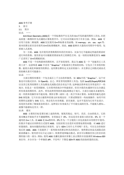
海伦娜血小板聚集仪aggRAM新建Worklist步骤
Agg RAM TM血小板聚集仪新建Worklist步骤运行仪器控制软HemoRam后,点击file→worklist或图标入工作列表窗口在Worklist ID输入工作列表名称(如ADP+AA)Test Type栏中从下拉菜单中选择Platelet Aggregation血小板聚集检测,Test栏选择要做的诱导剂检测。
(如Test栏选择Adenosine Diphosphate则4个通道默认为Adenosine Diphosphate诱导剂检测血小板聚集;带*号的是组合检测,可以根据所组合项目选择*Screen2或3)Stir Speed 为磁珠转数,默认为600rpm。
每个通道可以在Reagent 栏中从下拉菜单选择不同的诱导剂,可将默认的诱导剂修改实际要选择的诱导剂类型,单项的不可修改。
Patient ID 栏输入要做检测的病人ID 号,如不填则仪器认为该通道不检测样本。
Unit of Measure 栏为所选择的诱导剂的浓度单位。
Concentration 栏为所选择的诱导剂的浓度。
Lot Number 栏为所选择的诱导剂的批号信息,可不填。
点击Save ,保存工作列表信息。
注意:每次在Worklist 中修改的诱导剂检测组合,并在Patient ID 输入了要检测标本的病人ID 号,则所做的组合检测项目修改将保存在工作列表中。
如在Patient ID 栏不输入病人ID 号,则下次在选择该Worklist 时,则将恢复为默认的诱导剂检测组合。
下表为各诱导剂的浓度单位和最终浓度试剂名称二磷酸腺苷肾上腺素胶原花生四稀酸花生四稀酸(2倍稀释)缩写ADP EPN COLL ACA ACA 最终浓度5umol /L75umol /L (0.075mmol/L )2.5ug /ml500ug /ml (0.5mg /ml))250ug /ml (0.25mg /ml))本文由心我飞羊根据aggAM 仪器操作手册编制,发布于百度文库,仅提供给仪器操作人员参考。
海尔洗衣机用户手册.pdf_1702095214.4677227说明书
lights (DRL)
PPooT(TwiwrPeMeePrrSr)ettsaasiiullggreaattMeeonitoring System
LLaannee DDVSeeAppOaarrFttFuurree WWaarrnniinngg ((LLDDWW))
Tur
On/Off Indicators Condition IndicaPPtooorwwseerr sslliiddiinngg ddoooorr
NEW STYLE 5/1/2013 7:27 AM PagIIeNN4SSTTRRUUMMEENNTT PPAANNEELL IINNDDIICCAATTOORRSS
Briefly appear with each engine start. Red and amber indicators are most critical. Blue
High beams on
T(T(FTTiuirrPPeeeMMl PPeSSErrc))xeeotssenssriouuormrreeliygMMhotosononnniittoorriinngg SSyysstteemm
CRU CRU
OFF (lRoecafitlel d on center panel)
AAFnnCttW ii--LLLAooo(dcwcbdkklitnaiBrBkierrrspa)a:rkkeeessuSSryyess:tteemm ((AABBSS))
Ma Ma
traint
System
Briefly
LLCooVlwewohsicbbelerraadSkktoaeeboiflfilrltuuy(iiAsdd)s,,s/bbtisarrt®aailk(kgVeeSaAssty)yesstteemm Seat belt reminder: appLLFeooBaawrwrsatkwoeoeiiinotllhvppesrrerereeaiadsscetsshuusbyrerseentelgmti(nse) start. Red
ODG数据制作手册(TDR3000)
TD-SCDMARAN系统TDR3000ODG数据制作手册TD-SCDMARAN系统RNCTDR3000ODG数据制作手册■ TDR3000 □ TDB18AE □ TDB36A □ TDB18C □ TDB144A□ OMC V3 产品类别:□其他:文档系统产品版本:V3.40.10资料版本:V2.0.0文档编号:DTM6.519.480 UMODG数据制作手册V2.0.0前言内容介绍《ODG数据制作手册》介绍了如何采用ODG工具快速制作RNC数据,批量增加、调整RNC数据,本文分八章和附录。
●数据制作流程:介绍工程中客服中心内部各部门的分工配合●概述:介绍了TDR3000 ODG数据制作工具的运行环境和软件安装。
●RNC配置模型及单板容量介绍:介绍了各种典型配置的模型和单板的性能容量●数据制作过程:主要说明制作一套RNC完整配置数据的过程和方法以及需要注意的参数配置。
●数据调整:数据部分或者整体修改的说明●数据升级说明:介绍了工程中的数据升级方法●特殊数据制作说明:几种特殊配置的数据制作方法介绍●输入参数说明:主要介绍了局间接口关键参数的含义和取值规则。
读者对象本书适合下列人员阅读:●参与工程和用户手册撰写的开发者。
●参与工程和用户手册维护的相关人员。
●RNC数据制作人员参考文档●《TDR3000地面参数说明手册》●《TDR3000无线网络和业务参数标定手册》ODG数据制作手册目录目录第1章工程中的数据制作流程 ..................................................................................... 1-11.1数据制作在工程中的位置....................................................................................................................... 1-11.2IuB口批量数据表.................................................................................................................................... 1-11.3机架板位图及软硬件版本对照表 ........................................................................................................... 1-21.4Iu口数据协调表 ...................................................................................................................................... 1-21.5基站传输对应信息表............................................................................................................................... 1-31.6TD网管IP地址规划 ............................................................................................................................... 1-31.7数据制作结果处理................................................................................................................................... 1-4第2章软件概述.......................................................................................................... 2-12.1运行环境.................................................................................................................................................. 2-12.2安装说明.................................................................................................................................................. 2-12.3软件安装目录介绍................................................................................................................................... 2-52.4软件简介.................................................................................................................................................. 2-5第3章RNC配置模型及单板容量介绍.......................................................................... 3-13.1RNC配置模型介绍.................................................................................................................................. 3-13.2RNC主要单板容量介绍.......................................................................................................................... 3-13.2.1全局控制处理板(GCPA-硬件板卡类型GMPA)...................................................................... 3-13.2.2无线网络信令处理板(RS PA-硬件板卡类型GMPA)............................................................... 3-43.2.3ONCA操作维护板(硬件板卡类型MNPA+GEIC)................................................................. 3-11第4章数据制作过程................................................................................................... 4-1第5章RNC(35万用户配置)数据制作过程 ............................................................... 5-15.1创建RNC网元 ........................................................................................................................................ 5-25.2RNC物理配置部分数据制作 .................................................................................................................. 5-45.3RNC基本数据制作.................................................................................................................................5-105.4批量创建IuB口数据..............................................................................................................................5-115.5批量创建Iu口数据.................................................................................................................................5-125.6数据校验、保存 .....................................................................................................................................5-145.7数据调整.................................................................................................................................................5-145.7.1批量修改一类对象的全部或者部分参数.................................................................................... 5-155.7.2批量修改Iu口参数 ..................................................................................................................... 5-155.7.3批量增加、删除Node B/小区..................................................................................................... 5-16第6章数据升级说明................................................................................................... 6-1第7章特殊数据制作说明............................................................................................ 7-27.1HSDPA小区制作说明............................................................................................................................. 7-2目录ODG数据制作手册7.2MBMS小区制作说明.............................................................................................................................. 7-4第8章输入参数说明................................................................................................... 8-18.1Iu口的参数说明 ...................................................................................................................................... 8-18.1.1Iu口批处理中IUCS-ATM信令点信息......................................................................................... 8-18.1.2Iu口批处理中IUCS-ATM信令链路............................................................................................. 8-28.1.3Iu口批处理中IUCS-ATM数据链路............................................................................................. 8-38.1.4Iu口批处理中IUCS-IP信令点信息.............................................................................................. 8-38.1.5Iu口批处理中IUCS-IP信令链路.................................................................................................. 8-58.1.6Iu口批处理中IUCS-IP数据链路.................................................................................................. 8-58.1.7Iu口批处理中IUPS-ATM-IP信令点信息..................................................................................... 8-58.1.8Iu口批处理中IUPS-ATM信令链路 ............................................................................................. 8-68.1.9Iu口批处理中IUPS-ATM-IPOA链路........................................................................................... 8-78.1.10Iu口批处理中IUPS-IP信令链路 .................................................................................................. 8-78.1.11Iu口批处理中IUPS-ATM-IP-IPPATH链路 .................................................................................. 8-88.1.12Iu口批处理中RNC本局信令点参数............................................................................................ 8-88.2Iub口的参数说明..................................................................................................................................... 8-88.2.1Node B批量数据管理--ATM-单端口 ............................................................................................ 8-88.2.2Node B批量数据管理-ATM双端口.............................................................................................. 8-98.2.3IUB口-ATM-数据链路................................................................................................................ 8-108.2.4NodeB批量数据管理-IP-单端口 ................................................................................................. 8-108.2.5NodeB批量数据管理-IP-双端口 ................................................................................................. 8-118.2.6IUB口-IP-数据链路..................................................................................................................... 8-128.2.7小区批量数据管理 ...................................................................................................................... 8-128.2.8邻小区 ......................................................................................................................................... 8-158.2.9邻RNC小区-TDD128 ................................................................................................................. 8-168.2.10邻RNC小区-GS M-GPRS............................................................................................................ 8-17附录A:缩略语.................................................................................................................... - 1 -附录B:信道功率配置............................................................................................................ - 2 -附录C:文档修订记录 ......................................................................................................... - 6 -ODG数据制作手册目录图 1-1 工程中的数据制作流程图 .............................................................................................................................1-1图 2-1 运行安装文件..................................................................................................................................................2-1图 2-2 安装向导界面.................................................................................................................................................2-2图 2-3 协议条款 ........................................................................................................................................................2-2图 2-4 选择安装路径................................................................................................................................................2-3图 2-5 安装导示信息.................................................................................................................................................2-4图 2-6 开始安装之后的导示信息 ..............................................................................................................................2-4图 2-7 安装完成 ........................................................................................................................................................2-5图 4-1数据制作过程流程图......................................................................................................................................4-1图 5-1 35万用户的机架配置图.................................................................................................................................5-1图 5-2 创建RNC网元...............................................................................................................................................5-2图 5-3 创建成功后的界面.........................................................................................................................................5-3图 5-4 RNC网元界面................................................................................................................................................5-4图 5-5 快速创建机架和机框.....................................................................................................................................5-5图 5-6 机架机框创建完成后的界面..........................................................................................................................5-5图 5-7 创建GCPA板 ................................................................................................................................................5-6图 5-8 创建ONCA板................................................................................................................................................5-7图 5-9 创建RSPA板.................................................................................................................................................5-7图 5-10 创建GTPU板...............................................................................................................................................5-8图 5-11 创建CASA板...............................................................................................................................................5-9图 5-12 创建接口板IPPort ...................................................................................................................................... 5-10图 5-13 快速创建IMA组........................................................................................................................................ 5-10图 5-14 快速创建RNC基本数据............................................................................................................................ 5-11图 5-15 IuB口数据导入界面................................................................................................................................... 5-12图 5-16 Iu口数据导入界面 ..................................................................................................................................... 5-13图 5-17 PLMN信息界面 ......................................................................................................................................... 5-14图 5-18 SCCP子系统界面........................................................................................................... 错误!未定义书签。
PRIMER 6使用手册
PRIMER 6使用手册参考书:Primer V6 User manual Tutorial软件界面与功能第一部分数据一、输入数据1. PRIMER 自带数据格式:pri,sid,agg,ppl,pwk;2. 外部数据:xls,txt,csv;二、输出数据1. PRIMER 自带数据格式:pri,sid,agg,ppl,pwk;2. 数据结果:txt,rtf;3. 图形结果:emf,tif,jag,bmp,png;三、缺失值的处理1. Tools>Missing数据格式范例第二部分因子Factor一、作用因子数据与生物数据共同存在,常用于分组;二、操作Edit>Factor>可进行添加、删除、合并等操作;第三部分分析-预处理Pre-treatment一、作用对原始数据进行预处理,有利于后续的分析;二、操作1. 标准化:Analyse>Pre-treatment>Standardise2. 数据转换:Analyse>Pre-treatment>Transforming(Overall) >Square root, Fourth root, Log(X+1), Presence/Absence;3. 标准正态化:Analyse>Pre-treatment>Normalise variables4. 其他;第四部分分析-相似Resemblance一、作用将原始数据转换为相似矩阵,是后续分析方法的重要前提;二、操作1. 一般在计算相似矩阵之前,先进行数据转换;2. Analyse>Resemblance;3. Bray-Curtis相似性:比较群落相似性;4. Euclidean distances:欧氏距离即最简单的几何距离;第五部分分析-层次聚类Hierarchical clustering一、操作1. 相似矩阵,Analyse>CLUSTER;2. 单连接聚合分类:single linkage,分组梯度明显;完全连接聚合分类:complete linkage,产生较多小的分离的组;平均聚合分类:group linkage,介于上述两者之间;3. 图形调整:右击图形,点击相应选项操作即可;可改变文字、图例、标题、颜色、方向、颜色尺寸等;4. 增加标注线:Graph>Special>Show slice;5. 相似性检验:Analyse>SIMPROF;第六部分分析-非参数多维尺度分析MDS一、原理根据具有很多维度的样本或变量之间的相似性(距离近)或非相似性(距离远,即通过计算其距离)来对其进行分类的一种统计学研究方法。
高云 GW1NZ 系列 FPGA 数据手册说明书
GW1NZ系列FPGA产品数据手册DS841-2.1, 2023-07-20版权所有© 2023广东高云半导体科技股份有限公司,Gowin,小蜜蜂,LittleBee,高云均为广东高云半导体科技股份有限公司注册商标, 本手册中提到的其他任何商标,其所有权利属其拥有者所有。
未经本公司书面许可,任何单位和个人都不得擅自摘抄、复制、翻译本文档内容的部分或全部,并不得以任何形式传播。
免责声明本文档并未授予任何知识产权的许可,并未以明示或暗示,或以禁止发言或其它方式授予任何知识产权许可。
除高云半导体在其产品的销售条款和条件中声明的责任之外,高云半导体概不承担任何法律或非法律责任。
高云半导体对高云半导体产品的销售和/或使用不作任何明示或暗示的担保,包括对产品的特定用途适用性、适销性或对任何专利权、版权或其它知识产权的侵权责任等,均不作担保。
高云半导体对文档中包含的文字、图片及其它内容的准确性和完整性不承担任何法律或非法律责任,高云半导体保留修改文档中任何内容的权利,恕不另行通知。
高云半导体不承诺对这些文档进行适时的更新。
版本信息目录目录 (i)图目录 (iv)表目录 (v)1 关于本手册 (1)1.1 手册内容 (1)1.2 相关文档 (1)1.3 术语、缩略语 (2)1.4 技术支持与反馈 (2)2 产品概述 (3)2.1 特性概述 (3)2.2 产品信息列表 (5)2.3 封装信息列表 (5)3 结构介绍 (7)3.1 结构框图 (7)3.2 可配置功能单元 (9)3.3 输入输出模块 (10)3.3.1 I/O电平标准 (11)3.3.2 真LVDS设计(GW1NZ-2) (16)3.3.3 I/O逻辑 (17)3.3.4 I/O逻辑工作模式 (19)3.4 I3C总线模块(GW1NZ-1) (19)3.4.1 概述 (19)3.4.2 特性 (19)3.4.3 端口信号 (20)SPMI模块(GW1NZ-1) (22)3.4.4 概述 (22)3.4.5 端口信号 (22)3.5 块状静态随机存储器模块 (22)3.5.2 存储器配置模式 (23)3.5.3 存储器混合数据宽度配置 (25)3.5.4 字节使能功能配置 (25)3.5.5 校验位功能配置 (25)3.5.6 同步操作 (26)3.5.7 上电情况 (26)3.5.8 BSRAM操作模式 (26)3.5.9 时钟模式 (27)3.6 用户闪存资源(GW1NZ-1) (29)3.6.1 特性 (29)3.6.2 模式 (29)3.7 用户闪存资源(GW1NZ-2) (29)3.7.1 简介 (29)3.8 MIPI D-PHY(GW1NZ-2) (30)3.8.1 硬核MIPI D-PHY RX(GW1NZ-2) (30)3.8.2 GPIO支持以MIPI IO模式实现MIPI D-PHY RX/TX(GW1NZ-2) (30)3.9 时钟 (31)3.9.1 全局时钟网络 (31)3.9.2 锁相环 (31)3.9.3 高速时钟 (32)3.10 长线 (32)3.11 全局复置位 (32)3.12 编程配置 (32)3.12.1 SRAM编程 (33)3.12.2 Flash编程 (33)3.13 片内晶振 (33)4 电气特性 (34)4.1 工作条件 (34)4.1.1 绝对最大范围 (34)4.1.2 推荐工作范围 (34)4.1.3 电源上升斜率 (35)4.1.4 热插拔特性 (35)4.1.5 POR特性 (35)4.2 ESD性能 (36)4.3 DC电气特性 (37)4.3.1 推荐工作范围DC电气特性 (37)4.3.3 I/O推荐工作条件 (41)4.3.4 单端I/O DC电气特性 (42)4.4 AC开关特性 (43)4.4.1 CFU开关特性 (43)4.4.2 Gearbox开关特性 (43)4.4.3 时钟和I/O开关特性 (43)4.4.4 BSRAM开关特性 (44)4.4.5 片内晶振开关特性 (44)4.4.6 锁相环开关特性 (45)4.5 用户闪存电气特性 (46)4.5.1 DC电气特性 (46)4.5.2 时序参数[1],[5],[6] (48)4.5.3 操作时序图 (49)4.6 编程接口时序标准 (50)5 器件订货信息 (51)5.1 器件命名 (51)5.2 器件封装标识 (52)图目录图3-1 GW1NZ-1器件结构概念示意图 (7)图3-2 GW1NZ-2器件结构概念示意图 (8)图3-3 CFU结构示意图 (9)图3-4 IOB结构示意图 (10)图3-5 GW1NZ的I/O Bank分布示意图(GW1NZ-1) (11)图3-6 GW1NZ的I/O Bank分布示意图(GW1NZ-2) (11)图3-7真LVDS设计参考框图 (17)图3-8 I/O逻辑输入输出示意图 (17)图3-9 IODELAY示意图 (18)图3-10 GW1NZ的I/O寄存器示意图 (18)图3-11 GW1NZ的IEM示意图 (19)图3-12单端口、伪双端口及双端口模式下的流水线模式 (26)图3-13独立时钟模式 (28)图3-14读写时钟模式 (28)图3-15单端口时钟模式 (28)图3-16 GW1NZ-1 HCLK示意图 (32)图3-17 GW1NZ-2 HCLK示意图 (32)图4-1 读操作模式 (49)图4-2 写入操作模式 (49)图4-3 擦除操作模式 (50)图5-1器件命名方法示例–ES (51)图5-2器件命名方法示例–Production (51)图5-3器件封装标识 (52)表目录表1-1术语、缩略语 (2)表2-1产品信息列表 (5)表2-2产品封装和最大用户I/O信息列表 (5)表3-1 GW1NZ-1系列FPGA产品支持的输出I/O类型及部分可选配置 (12)表3-2 GW1NZ-1支持的输入I/O类型及部分可选配置 (12)表3-3 GW1NZ-2支持的输出I/O类型及部分可选配置 (13)表3-4 GW1NZ-2支持的输入I/O类型及部分可选配置 (15)表3-5 端口介绍 (18)表3-6 I3C端口信号 (21)表3-7 SPMI接口信号 (22)表3-8存储器配置列表 (23)表3-9双端口混合读写数据宽度配置列表 (25)表3-10伪双端口混合读写数据宽度配置列表 (25)表3-11时钟模式配置列表 (27)表3-12器件支持的用户闪存模式 (29)表3-13片内晶振的输出频率选项 (33)表4-1绝对最大范围 (34)表4-2推荐工作范围[1] (34)表4-3电源上升斜率 (35)表4-4热插拔特性 (35)表4-5 POR电压参数 (35)表4-6 GW1NZ ESD - HBM (36)表4-7 GW1NZ ESD - CDM (36)表4-8推荐工作范围内DC电气特性 (37)表4-9静态电流(LV版本) (39)表4-10静态电流(GW1NZ-1, ZV版本) (39)表4-11静态电流(GW1NZ-2, ZV版本)[1],[3],[4] (40)表4-12 I/O推荐工作条件 (41)表4-13单端I/O DC电气特性 (42)表4-14 CFU时序参数 (43)表4-15 Gearbox时序参数 (43)表4-16外部开关特性 (43)表4-17 BSRAM时序参数 (44)表4-18片内晶振特性参数 (44)表4-19锁相环特性参数 (45)表4-20 GW1NZ-1用户闪存DC电气特性 (46)表4-21 GW1NZ-2器件用户闪存DC电气特性[4] (47)表4-22用户闪存时序参数 (48)Preliminary1关于本手册 1.1手册内容1关于本手册1.1手册内容GW1NZ系列FPGA产品数据手册主要包括高云半导体GW1NZ系列FPGA产品特性概述、产品资源信息、内部结构介绍、电气特性以及器件订货信息。
- 1、下载文档前请自行甄别文档内容的完整性,平台不提供额外的编辑、内容补充、找答案等附加服务。
- 2、"仅部分预览"的文档,不可在线预览部分如存在完整性等问题,可反馈申请退款(可完整预览的文档不适用该条件!)。
- 3、如文档侵犯您的权益,请联系客服反馈,我们会尽快为您处理(人工客服工作时间:9:00-18:30)。
unsigned stride_abs() const; T* row_ptr(int, int y, unsigned); T* row_ptr(int y); const T* row_ptr(int y) const; row_data row (int y) const; T const* const* rows() const; template<class RenBuf> void copy_from(const RenBuf& src); void clear(T value) };
unsigned width, unsigned height, const char* file_name) {
FILE* fd = fopen(file_name, "wb"); if(fd) {
fprintf(fd, "P6 %d %d 255 ", width, height); fwrite(buf, 1, width * height * 3, fd); fclose(fd); return true; } return false; }
int main() {
// In the first example we do the following: //-------------------// Allocate the buffer. // Clear the buffer, for now "manually" // Create the rendering buffer object // Do something simple, draw a diagonal line // Write the buffer to agg_test.ppm // Free memory
void attach(T* buf, unsigned width, unsigned height, int stride);
T* buf();
const T* buf() const;
unsigned width() const;
unsigned height() const;
int
stride() const;
素的开头)。为申请和释放这块存储区是使用者的责任,你可以使用任何可行的方式来申请和释放内存, 比如使用系统提供的 API 函数,或是简单的用内存分配器(译注:应该是 new、delete、malloc、free 等), 甚至是直接使用一个静态数组。在上面这个例子中,因为每个像素要占用 3 个字节,所以我们申请了 width*height*3 字节的内存,在实际内存中是不存在“行”这种布局方式的,但这样做可以提高程序的性 能,而且有时候在使用 API 的时候需要。
unsigned i; for(i = 0; i < rbuf.height()/2; ++i) {
// Get the pointer to the beginning of the i-th row (Y-coordinate) // and shift it to the i-th position, that is, X-coordinate. //--------------unsigned char* ptr = rbuf.row_ptr(i) + i * 3;
// PutPixel, very sophisticated, huh? :)27; // R *ptr++ = 200; // G *ptr++ = 98; // B }
draw_black_frame(rbuf); write_ppm(buffer, frame_width, frame_height, "agg_test.ppm");
// Draw a black frame around the rendering buffer, assuming it has // RGB-structure, one byte per color component //-------------------------------------------------void draw_black_frame(agg::rendering_buffer& rbuf) {
1.2 Class rendering_buffer
包含文件: agg_rendering_buffer.h rendering_buffer 这个类保存了指向每一行像素的指针,基本上这个类做的事就是这些了。看起来 好像不是什么了不起的事,不过我们还是继续分析下去。这个类的接口和功能都很简单,它只是模板类 row_ptr_cache 的一个 typedef 而已:
那么结果将变成这样:
然后,我们试下将 rendering buffer 附着(attach)到被分配的内存区的某部分。这个修改会使得 rendering buffer 两次附着在同一块内存区上,第一次是整个被分配的内存区域,第二次是其中的一部 分:
int main() {
unsigned char* buffer = new unsigned char[frame_width * frame_height * 3];
delete [] buffer; return 0; }
在这个例子中,你甚至不需要链接任何的 AGG 的代码文件,你只需要在你的编译器命令行中设置好 AGG 的包含路径就行了。编译并运行它,你会看到现图所示的结果:
这个例子中几乎所有东西都“手工打制”的,使用的唯一一个现成的类是 rendering_buffer。这个类 本身并不知道关于内存中像素格式的任何信息,它只是保存了一个数组,数组中的元素分别指向每行(像
unsigned i; for(i = 0; i < rbuf.height(); ++i) {
unsigned char* p = rbuf.row_ptr(i); *p++ = 0; *p++ = 0; *p++ = 0; p += (rbuf.width() - 2) * 3; *p++ = 0; *p++ = 0; *p++ = 0; } memset(rbuf.row_ptr(0), 0, rbuf.width() * 3); memset(rbuf.row_ptr(rbuf.height() - 1), 0, rbuf.width() * 3); }
typedef row_ptr_cache<int8u> rendering_buffer;
row_prt_cache 这个类的接口的功能如下:
template<class T> class row_ptr_cache
{
public:
row_ptr_cache();
row_ptr_cache(T* buf, unsigned width, unsigned height, int stride);
AGG 中文手册
1 渲染内存 Rendering Buffer
我们先从这里开始:在内存中开辟一块存储区,然后将它的内容以最简单的光栅格式写到文件中,也就 是 PPM(Portable Pixel Map)格式。虽然 Windows 对这种格式并没有原生的支持,但很多图像浏览器和 转换器都能使用这种格式,比如 IrfanView()。所有 AGG 的控制台例子都使用了 P6 256 格式,也就是 RGB,每个字节代码一个颜色。现在假设我们将在下图所示的 RGB-buffer 内存区中工 作:
这个类的实现里没有使用断言或是验证的措施,所以,使用者有责任在用这个类对象时正确地将它初 始化到实际的内存块中,这可以在构造函数中完成,也可以使用 attach() 函数。它们的参数解释如下:
buf
— 指向内存块的指针。
width — 以像素为单位表示的图像宽度。rendering buffer(渲染内存区)并不知道像
BMP)。另外,这个参数允许使用者可以像操作整个内存区块一样,操作其中任意一个“矩形”内
存区。
attach()函数会改变缓冲区或是它的参数,它自己会为“行指针”数组重新分配内存,所以你可以在任何 时候调用它。当(且仅当)新的 height 值比之前使用过的最大的 height 值还要大时,它才会重新申请内 存。
unsigned char* buffer = new unsigned char[frame_width * frame_height * 3];
memset(buffer, 255, frame_width * frame_height * 3);
agg::rendering_buffer rbuf(buffer, frame_width, frame_height, frame_width * 3);
memset(buffer, 255, frame_width * frame_height * 3);
agg::rendering_buffer rbuf(buffer, frame_width, frame_height, frame_width * 3);
1.1 第一个简单例子
#include <stdio.h> #include <string.h> #include "agg_rendering_buffer.h"
enum {
frame_width = 320, frame_height = 200 };
// Writing the buffer to a .PPM file, assuming it has // RGB-structure, one byte per color component //-------------------------------------------------bool write_ppm(const unsigned char* buf,