CP350功率表说明书
梅特勒托利多 ACT350 ACT350 增强型 ACT350xx 电子称重仪表用户手册说明书

3.4. LED 状态灯 ............................................................................................................ 20 3.5. 拨码开关和主复位................................................................................................ 21
2.3. 连接........................................................................................................................ 10
2.3.1.
电源............................................................................................................. 12
1.4. 包装内容清单.......................................................................................................... 3
1.5. 物理尺寸.................................................................................................................. 4
3.6.5.
去皮............................................................................................................. 23
MULTI-WELD 350操作手册说明书
350Operator’s ManualSave for future referenceDate PurchasedCode: (ex: 10859)Serial:(ex: U1060512345)For use with machines having Code Numbers:10645, 10736, 11148, 11854Register your machine: /registerAuthorized Service and Distributor Locator: /locatorSAFETYTECHNICAL SPECIFICATIONS - Multi-Weld 350 (K1735-1)350340350340350340350340MU L TI -S OU RC EM UL T I-SO UR CEMULTI-SOURCE• Converter welding controls are near the arc without Array long control cables, and a receptacle is provided for an optional remote for even closer user output control.Simple• Easy installation with 10 ft. (3m) work clip lead and user preference quick-connect "pigtails" for input and electrode weld cables.• Easy setup with only a few intuitive welding controls and lit displays; including a single Power/Mode switch with Input level light, and a single presettable Output Control with separate digital meters for Amps and Volts, featuring post-weld five second memory display.• Easy Service with quick to replace cable "pig-tails"and "plug-in" assembly modules, including accessible PC boards and interchangeable "plug-n-play" panel instruments.Robust• Capacity is rated for continuous operation at 350 amps in 50°C (122°F) ambient temperature, and can be paralleled to multiply CC mode output rat-ing.• Overload protection is provided with electronic lim-iting of output current, and with thermostat and over-voltage shutdown protection which automati-cally reset.• Outdoor operation protected with sealed control and power electronics compartments, with sealed interconnections, housing "potted" circuit boards, and using "Central-Air" cooling with "Fan-As-Needed" for less dirt intake.• Handling (and mishandling protection) is enhanced with light, but durably designed, aluminum con-struction with front to back, top and bottom, han-dles (also serving as "roll bar" and skid), and a sheetmetal shell attached with 1/4" steel threadedfasteners.The Multi-Weld 350 is provided with a 6-pin remote receptacle to permit use with the 25ft.(7.6 m) K857 or 100ft.(30.4 m) K857-1 Remote Output Control options, or with the LN-25 equipped with the K444-1 Remote Control option. These Remotes have single-turn reso-lution on a Min to Max numbered dialplate.CV MODE WIRE WELDINGThe Converter in CV mode was designed for use with an arc-powered wire feeder like the LN-25. The Converter output is always "hot" when the mode switch is not OFF, so it is recommended that the LN-25 model be equipped with the internal contactor in order to have a "cold" electrode when the gun trigger is released.The CV mode recommended processes are positive (+) polarity wire welding within the output capacity of the Converter, including:CC MODE STICK WELDINGAND GOUGINGThe CC mode recommended processes are positive (+) polarity stick and arc gouging within the output capacity of single, or paralleled, Converters; including: QUICK-CONNECT "PIG-TAILS"The Multi-Weld 350 is factory provided with two 21 in.(53 cm) long 2/0 AWG (70mm2 ) "pig-tail" cables with their 0.5"(13mm) hole lug ends routed through the "INPUT + "(on back) and "ELECTRODE + "(on front) cable channels of the Converter and attached to the bottom-accessed covered cable connection studs. Attach the preferred standard user-provided Quick-connect terminal (such as Lincoln Twist-Mate or Tweco 2-MPC type) to the cut-off end of these cables. Use the female connector on the "ELECTRODE +"cable and the male connector on the "INPUT +" cable.INTER-CONNECTION OF CONVERTERSThe input and electrode cables of the Multi-Weld 350 Converters may be inter-connected in a Multi-Weld System using any combination of Distribution Box(es)(see Figure 1), paralleling ( CC mode only) and "daisy-chaining" (see Figure 2) which best fits thefield application setup within the capacity of the power source supplying the system:Figure 2W W WorW W (-)Work Lead adtoer r Sou ou rc rce s s tu tudMW-35350 0t oo WorkFRONT PANEL CONTROLSThese few instruments are basic to the operation and monitoring of the Converter. They are intuitively laid out so that the panelʼs left side is weld current related, and the right side is weld voltage related:(1) Input Power/ Mode Switch has three positions:Center is OFF which shuts off input power to theConverter.• Neither displays nor output is on if in OFFposition.Left is on for CC (constant current) welding mode.•Only AMPS digital meter is lit displaying thepreset current setting• Output will be on at o.c.v. (open circuit voltage).Right is on for CV (constant voltage) welding mode.• Only VOLTS digital meter is lit displaying thepreset voltage setting• Output will be on at the output voltage setting. (2) Output Control has 3-3/4 turn resolution withslip-clutch to prevent control pot damage.In CC mode it presets AMPS (30-350A range) when not welding, and adjusts actual arc current while welding.In CV mode it presets VOLTS (15-40v range) when not welding, and adjusts actual arc voltage while welding.(3) AMPS Digital Meter is a 3-1/2 digit LED meterwhich displays:Preset Amps in CC mode when not welding."Blank" in CV mode when not welding.Actual Amps while welding in both CC and CV modes.Disconnecting the Remoteʼs plug from this recep-tacle automatically transfers output control back to the panel Output Control (item (2) above).Remote output On/Off switching can also be done thru this Remote Control receptacle. by per-forming the following wiring changes:1. Making sure the input to the Converter isremoved, remove the case wraparound.2. Locate the 4-pin plug (P21) on the backpanel of the control box module, and cut thejumper lead looping from the back of theplug. (Refer to the Wiring Diagram in thismanual.) Insulate the cut lead ends andleave long enough to possibly splice backtogether again at some future time.3. Replace the case wraparound.4. Connect a user-provided remote switchbetween pins D and E of an MS3106A-18-12P plug (Lincoln part no. S12020-27 withS12024-1 cable clamp). See diagrambelow:Pin:Remote Function:A Max. of 10K potB Wiper of 10K potC Min. of 10K potD Output SwitchE Output SwitchF No connection5. Connect this switch plug to the Multi-Weld350 Remote Control Receptacle (10) withswitch opened. Closing the switch activatesthe Converter output.PARALLELED CONVERTERSMulti-Weld 350 converters that are paralleled (see INTER-CONNECTION OF CONVERTERS in the INSTALLATION section) must each be set up in the same manner in order to manage the arc current drawn from each:1) Set to CC mode with CC SLOPE switch set toSTICK/GOUGE.2) Preset Output Controls of both paralleledConverters to ~1/2 desired total Amps.If arc current from each Converter gets too out of bal-ance (primarily a problem if trying to use CV mode) the hotter running Converter could go into current-lim-iting and/or Thermal shutdown (See OVER-TEMPER-ATURE SHUTDOWN in the INSTALLATION section), which might then overload the other, or at least inter-rupt the operatorʼs process. However, no damage will occur to the Converters.REMOTE CONTROL OF PARALLELED CONVERTERS(FOR CC STICK/GOUGE MODE ONLY)Full Range remote control can be accomplished with a separate optional Remote output control (see INSTALLATION section) connected to each Converter. The current contribution of each Converter will depend on its remote output setting.Partial Range remote control can be accomplished with a single Remote Control connected to the output Converter with the input Converter preset with its panel Output Control to below the minimum desired output range. The Remote Control, connected to the output Converter, will control its output to add to the preset level.Remote Output On/Off switching maybe setup for each of the paralleled Converters, but isolated, or double-pole, switches must be used to activate each separately but simultaneously.D-1MAINTENANCED-13. Holding the unit by the front handles, so the back is facing down, shake the loose debris out of the unit. Raking out the heatsink fins may be necessary for jammed debris.4. If necessary, remove the case wraparound cover and using the skid handles to hold upside down carefully dump out any remaining loose debris,or carefully blow out using low pressure air.5. Reassemble the cleaned out Converter by reversing the above steps.DIGITAL METER CALIBRATIONIf calibration of either digital meter is ever necessary,meter calibration adjustment trimmers are provided on the Weld Control PC board inside the Control Module (see Figure 5). Calibration must be done with an Output current load, so meters are displaying Actual (not Preset) values. It is recommended that the cali-bration levels be near the rating plate values, for best accuracy, and compared to "master" meters with bet-ter than 2% accuracy.The accuracy of Actual AMPS meter should be within 3% of the welding amps monitored. The AMPS meter trimmer (R561) is located near the center of the Weld Control PC board just below the VOLTS meter trim-mer (R562). Clockwise rotation of the trimmer adjust-ment screw will decrease the meter reading.The accuracy of Actual VOLTS meter should be within 3% of the welding volts monitored. The VOLTS meter trimmer (R562) is located near the center of the Weld Control PC board just above the AMPS meter trim-mer (R561). Clockwise rotation of the trimmer adjust-ment screw will decrease the meter reading. The "master" voltmeter should be connected as close as possible to the "ELECTRODE +" stud and "WORK-"lead bolt, for best accuracy.MAINTENANCEThe only maintenance which may be required for the Multi-Weld 350 is to clean out any accumulated dirt and debris which could contaminate internal compo-nents, or obstruct proper cooling of the power compo-nents resulting in premature over-temperature shut-down.The recommended cleaning procedure is as follows:1. Be sure to disconnect the Converterʼs input cable to remove its input power.2. Remove the four screws securing the rear louver panel, and remove the panel to expose the cool-ing tunnel heatsinks. (See Figure 4 below):Figure 4This Troubleshooting Guide is provided to help you locate and repair possible machine malfunctions.Simply follow the three-step procedure listed below.Step 1.LOCATE PROBLEM (SYMPTOM).Look under the column labeled “PROBLEM (SYMP-TOMS)”. This column describes possible symptoms that the machine may exhibit. Find the listing that best describes the symptom that the machine is exhibiting.Step 2.POSSIBLE CAUSE.The second column labeled “POSSIBLE CAUSE” lists the obvious external possibilities that may contributeto the machine symptom.Step 3.RECOMMENDED COURSE OF ACTIONThis column provides a course of action for the Possible Cause, generally it states to contact your local Lincoln Authorized Field Service Facility.If you do not understand or are unable to perform the Recommended Course of Action safely, contact your local Lincoln Authorized Field Service Facility.HOW TO USE TROUBLESHOOTING GUIDEService and Repair should only be performed by Lincoln Electric Factory Trained Personnel.Unauthorized repairs performed on this equipment may result in danger to the technician and machine operator and will invalidate your factory warranty. For your safety and to avoid Electrical Shock, please observe all safety notes and precautions detailed throughout this manual.__________________________________________________________________________E : T h i s d i a g r a m i s f o r r e f e r e n c e o n l y . I t m a y n o t b e a c c u r a t e f o r a l l m a c h i n e s c o v e r e d b y t h i s m a n u a l. T h e s p e c i f i c d i a g r a m f o r a p a r t i c u l a r c o d e i s p a s t e d i n s i d e t h e i n e o n o n e o f t h e e n c l o s u r e p a n e l s . I f t h e d i a g r a m i s i l l e g i b l e , w r i t e t o t h e S e r v i c e D e p a r t m e n t f o r a r e p l a c e m e n t . G i v e t h e e q u i p m e n t c o d e n u m b e r .JapaneseChineseKoreanArabicLEIA E COMPREENDA AS INSTRUÇÕES DO FABRICANTE PARA ESTE EQUIPAMENTO E AS PARTES DE USO, E SIGA AS PRÁTICAS DE SEGURANÇA DO EMPREGADOR.JapaneseChineseKoreanArabicREAD AND UNDERSTAND THE MANUFACTURER’S INSTRUCTION FOR THIS EQUIPMENT AND THE CONSUMABLES TO BE USED AND FOLLOW YOUR EMPLOYER’S SAFETY PRACTICES.SE RECOMIENDA LEER Y ENTENDER LAS INSTRUCCIONES DEL FABRICANTE PARA EL USO DE ESTE EQUIPO Y LOS CONSUMIBLES QUE VA A UTILIZAR, SIGA LAS MEDIDAS DE SEGURIDAD DE SU SUPERVISOR.LISEZ ET COMPRENEZ LES INSTRUCTIONS DU FABRICANT EN CE QUI REGARDE CET EQUIPMENT ET LES PRODUITS A ETRE EMPLOYES ET SUIVEZ LES PROCEDURES DE SECURITE DE VOTRE EMPLOYEUR.LESEN SIE UND BEFOLGEN SIE DIE BETRIEBSANLEITUNG DER ANLAGE UND DEN ELEKTRODENEINSATZ DES HER-STELLERS. DIE UNFALLVERHÜTUNGSVORSCHRIFTEN DES ARBEITGEBERS SIND EBENFALLS ZU BEACHTEN.• Sales and Service through Subsidiaries and Distributors Worldwide •Cleveland, Ohio 44117-1199 U.S.A. TEL: 216.481.8100 FAX: 216.486.1751 WEB SITE: 。
LRS-350 350W单输出切换电源说明书

PACKING
0.76Kg; 15pcs/12.4Kg/0.78CUFT
NOTE
℃ ℃/ ().
※ : , https:///serviceDisclaimer.aspx
File Name:LRS-350-SPEC 2021-09-17
Case No.207A
Unit:mm
9.5
8
LED +V ADJ.
9 8 7 6 5 4 3 2 1
4-M4 L=3mm
15
32.5
150
2
12.8 6.9
6.5 6.5
36.7
50
115
47.45
32.5
16
12.5 30
Air flow direction
4-M4(Both Sides) L=5mm
RATED POWER
198W
252W
300W
348W
348W
350.4W 349.2W 350.4W
RIPPLE & NOISE (max.) Note.2 150mVp-p 150mVp-p 150mVp-p 150mVp-p 150mVp-p 150mVp-p 200mVp-p 200mVp-p
ENVIRONMENT STORAGE TEMP., HUMIDITY -40 ~ +85℃, 10 ~ 95% RH
TEMP. COEFFICIENT
±0.03%/℃ (0 ~ 50℃)
VIBRATION
10 ~ 500Hz, 5G 10min./1cycle, 60min. each along X, Y, Z axes
Terminal Pin No. Assignment :
350Pro 中文说明书

t esto 350-EPA,-Pro手操器和testo 350-EPA,-Pro/-XL烟气分析箱操作手册 中文2 一般说明一般说明请仔细阅读本文,以便在投入使用前,先熟悉产品的操作。
如有必要,请把本手册放在手边,以供取阅。
本文描述了testo 350-EPA,-Pro 测量系统的操作说明。
Testo 350-XL 的一些标准功能,对于testo 350-EPA,-Pro 烟气分析仪来说则是选配功能。
两种烟气分析仪分别使用testo 350-EPA,-Pro 手操器。
也就是说,本手册描述的功能和操作,适用于testo 350-EPA,-Pro 手操器和testo 350-EPA, Pro 烟气分析箱。
提示标识含义建议警告:warning!如果未采取特定的预防措施,可能会引起严重的人身伤害请仔细阅读警告提示,采取预防措施警告:warning!如果未采取特定的预防措施,可能会造成轻微的人身伤害,或设备损坏请仔细阅读警告提示,采取预防措施重要信息请特别注意Text仪器屏幕显示文字 -按键请按键打印的功能键 请按功能键简明版操作步骤 见简易格式,3页一般说明简易格式本手册使用一些简易格式,来描述操作步骤(例如,调用功能)例如:调用诊断功能简易格式:要求的操作步骤:1.打开主菜单:2.选择菜单项:3.确认选择:4.选择功能诊断:5.确认选择:34 内容内容一般说明 (2)内容 (4)A. 安全说明 (8)B. 预定用途 (9)C. 产品描述 (10)手操器 (10)C.1C.1.1 手操器概述 (10)C.1.2 键盘 (11)C.1.3 显示屏 (11)手操器连接/接口 (14)C.1.4手操器电源 (14)C.1.5烟气分析箱 (15)C.2C.2.1 烟气分析箱概述 (15)C.2.2 LED状态显示灯 (16)C.2.3 烟气分析箱连接/接口 (16)烟气分析箱供电 (17)C.2.4功能/仪器选项 (17)C.2.5烟气探针 (17)C.3D 调试 (18)E 操作 (19)电源,电池/充电电池 (19)E.1更换电池 (19)E.1.1电池充电 (20)E.1.2电源供电 (21)E.1.3E.2探头传感器 (21)E.2.1 连接探头传感器 (21)E.2.2 使用烟气探针 (21)内容5 E.3 基本操作步骤 (22)连接系统部件 (22)E.3.1打开测量系统 (23)E.3.2调用功能 (24)E.3.3分配功能键 (25)E.3.4输入数值/名称 (26)E.3.5打印数据 (27)E.3.6E.3.7保存数据 (27)E.3.8关闭测量系统 (27)E.4 设置测量系统 (28)E.4.1设置语言 (28)设置日期/时间 (28)E.4.2设置燃料 (28)E.4.3编辑显示 (29)E.4.4设置地点 (30)E.4.5更改仪器名称 (31)E.4.6设置打印机 (31)E.4.7E.5 日常保养 (32)E.5.1冷凝槽/冷凝箱 (32)检查/替换过滤芯 (33)E.5.2E.5.3检测系统泄露 (33)F. 主菜单 (34)内存 (34)F.1F.1.1 读取 (34)F.1.2 程序 (34)F.1.3 删除内存 (36)F.1.4 释放内存? (36)F.2传感器 (36)F.2.1 校准 (36)F.2.2 打印传感器数据 (39)F.2.3 传感器状态 (39)输入 (39)F.3F.3.1 测量点编号/HCT (39)F.3.2 燃料 (40)F.3.3 O2参考值/CO2max (40)F.3.4 参数 (40)F.3.5 稀释 (41)F.3.6 露点/环境空气 (41)6 内容装置 (42)F.4F.4.1 更改日期 (42)F.4.2 视图 (42)F.4.3 打印机 (42)F.4.4 诊断 (43)F.4.5 配置 (43)F.4.6 密码 (43)服务 (44)F.5F.5.1 操作值 (44)F.5.2关闭 (44)地址 (44)F.5.3F.5.4 设备数据 (44)F.5.5 语言 (45)F.5.6 数据传输总线地址 (45)G. 测量 (46)准备测量 (46)G..1烟气测量 (47)G..2抽力/差压测量 (47)G..3风速测量 (48)G.4温差测量 (49)G.5测量编程/固体燃料测量 (49)G.6H. 保养和维修 (50)清洁仪器 (50)H.1更换/翻新传感器 (50)H.2重新校准传感器 (51)H.3清洁烟气探针 (51)H.4替换探针前置过滤器 (52)H.5替换热电偶 (52)H.6更换打印纸 (52)H.7更换电池/充电电池 (52)H.8H.9更换冷凝泵 (53)I. 问与答 (54)内容7J. 技术数据 (55)标准和测试 (55)J.1量程和精度 (55)J.2其他仪器数据 (57)J.3J.4计算原理 (58)J.4.1 燃料参数 (58)J.4.2 计算公式 (58)推荐的清洗时间 (61)J.5K. 附件/备件 (62)8 A. 安全说明A. 安全说明避免电气危险:> 不要在有电部件上或其附近使用本测量仪器和探头进行测量保护仪器:> 不要将测量仪器/测量元件与溶剂放在一起,并且不要使用任何干燥剂。
多功能功率表说明书
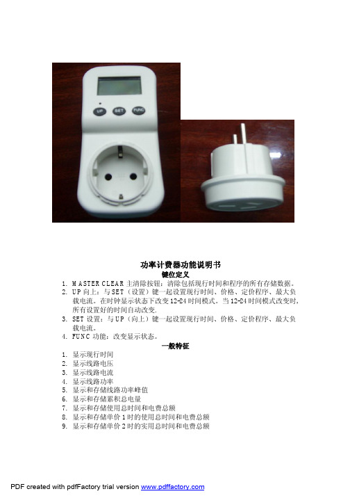
4. 再次按下 FUNC(功能)按钮一次后松开,功率表会显示最大线路功率和 出现最大线路功率的时间,功率因数。按下 FUNC(功能)按钮并保 持 5 秒钟,会在该状态下清除最大线路功率显示。
5. 再次按下 FUNC(功能)按钮一次后松开,功率表会显示现行时间和累计 功率因数
10. 显示线路频率 11. 显示功率因数 12. 可调节的最大负载电流和最大负载警告 13. 可调节的价格/千瓦时
总共有 11 个时间段的划分,如下所示: 星期一 星期二 星期三 星期四 星期五 星期六 星期日 星期一 星期二 星期三 星期四 星期五 星期一 星期二 星期三 星期四 星期五 星期六 星期日 星期一 星期二 星期三 星期四 星期五
2. 设置单价 2
PDF created with pdfFactory trial version
在设置完单价 1 后,按下 FUNC(功能)按钮一次后松开,重复上面的步骤
来设置单价 2。
3. 设置过载电流数据
设置完单价 2 后,按下 FUNC(功能)按钮一次后松开
PDF created with pdfFactory trial version
10. LCD 显示——当总电量或总电费溢出时,OVER(过多)就会同时闪亮。 设置现行时间
1. 在时钟显示模式下,按下 SET(设置)按钮一次,“WEEK DAY(周)” 就会同时闪烁,时钟换到 SET(设置)模式。你现在可以设置现行时钟 了。所有进入设置状态时,LCD 会显示”SET”.
d. 按下 SET(设置)按钮一次后松开,第四个最大负载的数字闪烁,
按下 UP(向上)来设置。
CPXDS-350,500使用说明书

牡丹江欧地希焊接机有限公司使用说明书/MAG焊接机 微电脑数字控制C02X D 5 0 0 SX D 3 5 0 S目 录1. 安全注意事项 (1)2. 敬请遵守的安全事项 (2)3. 使用注意事项 (5)4. 标准配置及附件 (6)5. 各部位名称及功能 (7)6. 必需的电源设备 (9)7. 搬运与设置 (10)8. 连接与安全接地 (11)9. 焊接准备 (15)10. 焊接操作 (17)11. 功能 (27)12. 维护保养及故障修理 (30)13. 零部件一览表 (40)14. 规格 (42)15. 关于售后服务 (45)No.C0180/C01811. 安全注意事项● 请在认真阅读本使用说明书后,正确使用。
● 本使用说明书所列注意事项,是为使您能安全使用机器、并使您及他人免受伤害。
● 本焊机设计、制造,虽然充分考虑了安全性,但在使用时,为避免发生重大人身事故,故务请遵守本使用说明书中所列注意事项。
● 错误操作焊机会引发不同等级的伤害、事故。
本使用说明书将危害等级分为3级,用注意标识符及警告用语予以警告,此标识符及警告用语在电焊机中亦表示相同的意思。
·注意标识符表示一般情况。
·上述重大人身事故是指失明、外伤、烫伤(高温、低温)、触电、骨折、中毒等,会遗留后遗症及须长期去医院进行治疗的伤害或死亡。
中度伤害及轻伤,指不必长期住院或长期去医院进行治疗的外伤、烫伤、触电等。
物质损失指涉及财产损失及机器损坏而引发的扩大损失。
No.C0180/C01812.敬请遵守的安全事项No.C0180/C0181 2.敬请遵守的安全事项(续)No.C0180/C01812.敬请遵守的安全事项(续)No.C0180/C01813. 使用注意事项●本焊机的额定负载持续率为XD500S: 500A 60% XD350S: 350A 50%●因焊枪等其他机器亦限制负载持续率,在一起配套使 用时请按其中额定负载持续率最低的为基准使用。
2XP350产品手册
4、『1#泵运行』指示灯亮时:1#泵处于正常运行、『1#泵运行』指示灯灭时:1#泵处于停止运行。
5、『1#泵故障』指示灯亮时:1#泵有故障出现、 『1#泵故障』指示灯灭时:1#泵未有故障出现。
根据数显屏显示的故障代码可以找出单一个故障点,故障代码描述贴在控制器外壳的侧面。
四、P03参数:启动转换时间·······
该参数定义降压启动方式在启动转换到运行的时间,P01 = 0无效。(出厂默认选择为7秒)
可设置范围:5、6、7、8、9、10、11、12、13、14、15,单位为:秒
设置方法:通过《√》按键进入菜单选项,利用《停止》按键或《1泵启动》按键上下调节选择设备匹配的启动转换时间。通过《 MENU 》按键保存直接进入下一菜单。
6、【1#泵允许/禁止】黄色按键是指:1#水泵的允许和禁止交替切换按键。
7、【2#泵允许/禁止】黄色按键是指:2#水泵的允许和禁止交替切换按键。
三、手动控制描述·······
当控制器处于『自动状态』时,通过按一下【手动/自动】蓝色按键,这时『手动状态』指示灯、『1#泵允许』指示灯、『2#泵允许』指示灯同时亮。这表示控制器处于手动控制模式,需要人工同过【停止】红色按键、【1#泵启动】绿色按键、【2#泵启动】绿色按键来控制启动或停止水泵,(并且远程控制信号不受控制)。但只能启动两台水泵的其中任意一台。
二、按键操作描述·······
1、【V/A 切换】蓝色按键是指:电源电压和水泵电流显示交替切换按键。
2、【 停 止 】红色按键是指:手动状态下1#水泵或2#水泵的停止按键。
3、【1#泵 启动】绿色按键是指:手动状态下1#水泵启动按键。
菲尼克斯电气ILC330_350可编程控制器用户手册
版本始于(HW) 01 01 02 02
版本始于(FW) 4.6F/1.41 4.6F/1.11 4.6F/1.20 4.6F/1.3F
订货号 2737193 2737203 2985819 2876928
6959_en_05
PHOENIX CONTACT
UM EN ILC 330/350
请阅读下列说明
使用符号的解释
特别注意符号指示那些不严格遵守可能会导致软硬件损坏或人身伤害 的操作步骤。
备注符号告诉您要进行正确无误的操作必须严格遵守的条件,它也向您 提供能节省您工作量的有关硬件的有效使用及软件优化方面的提示与 建议。 说明符号指示与讨论主题和产品相关的详细的信息源(手册、数据表、 文献等),这里也提供关于如何浏览手册的有用信息。
不管是特别提及还是其它的方式,技术数据中提供的信息并不附随保证。 这些信息并不包括质量保证,并不描述任何市场质量,也不会对质量保证 或特殊目的的适合性保证作出任何主张。
菲尼克斯电气有限公司对技术文档(尤其是数据表,安装指南,手册等) 中的错误或省略不担负责任。
上面提及的责任以及责任免除并不适用于必须承担的责任,例如根据产品 责任法,由于人身伤亡或健康损害或由于违反了重要的合同责任,存在预 谋或重大疏忽,则应承担相应的责任。但是,如果没有预谋或重大疏忽, 或责任因人身伤亡或健康损害而造成,则对违反重要的合同责任的破坏主 张限于合同典型的,可预见的损害。该决定并不意味着将检验负担变为用 户的损害。
ETH, ILC 350 ETH/M)............................................ 2-14 2.10 内部电路图 .............................................................................. 2-15 2.11 Inline可编程控制器的安装和拆卸 .......................................... 2-17 2.12 通信路径 .................................................................................. 2-21
I.C.T IR350插线SMT PCBA路由器说明书
1Inline SMT PCBA Router IR350 Introduction |I.C.T GroupI.C.T Inline SMT PCBA Router Machine I.C.T-IR350Introduce :I.C.T inline pcba router is a high-precision high-speed dual-platform on-line pcba router, which is used in smart phones, smart wear, smart home, tablet computers, automotive electronics, medical devices, aerospace, military and other fields. Features :1,New CCD system,new vision system can correspond to all kinds of pcb mark.with visual counterpoint correction function. 2,The sensor can monitor the milling cutter state in real time, and effectively prevent the continuous operation of the cutter. 3,Using high speed spindle, cutting stress is greatly reduced, precision is high, inertia is small, and response is fast. 4,Ion air gun will remove static electricity on PCB surface and prevent dust from adsorbing on PCB.5,Automatic loadering - picking and placing – cutting – unloadering pcba,unloadering solution can be option. 6,Adopt CNC special controller,high stability and strong anti-interference.7,The separated vacuum dust collector adopts high efficiency motor with high suction and low noise. 8,Realize automation, save manpower and improve quality.9,Automatic storage product information, automatic adjustment conveyor width, improve the speed of line change. 10,Loadering pcba the automatic splint function replaces the traditional cylinder and is more accurate. 11,Dual working platform to improve cutting efficiency.12,Pcba can be cut and move at the same time to improve productivity efficiency. 13,Standard MES or ERP connection ports, real-time connection to the central database. 14,Bar code camera is option, which can scan barcode automatically and upload.2Inline SMT PCBA Router IR350 Introduction |I.C.T GroupConfiguration :Feeding SystemThe new feeding system replaces the traditional cylinder structure to ensure more accurate feeding and automatic width adjustment of the conveyor. Unloading to conveyor belt, with detection function, easy to use at the back of the station, unloading conveyor modeis optional.Pick&Place SystemUsing precise double servo to pick and place Pcba instead of traditional cylinder (or double cylinder to take and place)Double servo screw structure pick and place Pcba will improve the accuracy.The Z1 axis is responsible for picking Pcba in and out of the board, while the Z2 axis is responsible for picking Pcba out and putting it in the next station after the cutting is completed. The traditional which has the disadvantages of slow speed. Dual mechanicalpick-and-place structure greatly improves operation efficiency and productivity.CCD camera alignment system, Milling cutter Auto-change system,Whole board scanning function,MES system,Precision Dust-proof Module, The UPH is calculated automatically.Intelligent Milling Tool Database,Automatic recording of products cut byeach milling cutter to achieve traceability3Inline SMT PCBA Router IR350 Introduction | I.C.T Group PartsBrand Place of origin X-axis servomoter Panasonic Japan Y-axis servomoter Panasonic Japan Z-axis servomoter Panasonic Japan Main-axis/ spindle NSK Japan CCD MINTRON Taiwan I/O Board I.C.T China Guide rail PMI/HIWIN Taiwan Ball screw PMI Taiwan Coupling NBK Japan Sensor Takex Japan Tank Chain IGUS Germany Flexible cable IGUS Germany Bearing NSK Japan Switch, Button TD,LJTaiwanSpecification :PCB Router I.C.T-IR350 Pcb Size 300*350mm Platform Number Double PCB thickness 0.3~6.0mmPCB support mode Multifunctional fixture, special fixtureX 、Y Cutting Speed 0~100mm/s Repeat Precision ± 0.01mm X 、Y 、Z Driving Method AC Servo motor X 、Y 、Z Control mode CNC controllerIon air gun≤±15v (ESD 12M09158A58)Operation and Data Storage PC System Cut Precision± 0.08mm Rotational Speed of the Main Shaft Max 80000rpm Voltage220V,50/60HZ Air Pressure Supply 4.5kg/cm2 Power Supply1.5kw Weight(with vacuum cleaner) 1100kg Dimension1930*1350*1700mm Dust Collection Method Vacuum cleaning Air volume of vacuum cleaner 28~35m³/min Vacuum cleaner Dimension 750*600*620mm Voltage of the Dust Collector380V,50/60HZ,3kw* I.C.T keeps working on quality and performance,specifications and appearance may be updated without particular notice.Thanks for choosing I.C.T.I.C.T looks forward to win-win cooperation.4Inline SMT PCBA Router IR350 Introduction | I.C.T Group。
SHP350系列AC-DC电源设备说明书
SHP350 Series•420 W High Line Output Power•Rugged Industrial Construction•Variable Speed Fan for Noise Reduction•-40 °C to +70 °C Operation• 5 V Standby•AC OK, Remote On/Off and Active Current Share•Screw Terminals•SEMI F47 Compliant• 3 Year WarrantyThe SHP350 AC-DC power supply provides upto 420 W of output power in a compact rugged mechanical package, suitable for a range of industrial applications.The unit comprises of a main output with voltages from 12-48 VDC and a 5 VDC standby supply which can be utilitsed with the signals and control features of the unit to provide detection of loss of AC input and remote on/off control.Multiple units can be used in parallel via the current share facility, providing higher power solutions. Inherently low earth leakage current, and conducted EMC compliance to Class B also simplify higher power system design.Packaged in a compact 7” (178 mm) x 3.6” (91 mm) x 2.1” (53 mm) and carrying IEC60950 family safety approvals, the SHP350 has a load dependant variable speed fan, is fully protected with overtemperature shutdown and provides -40 ºC start up and full power from -20 ºC to 50 ºC and 50% power at +70 ºC.Models and RatingsInput Voltage (VAC)Output CharacteristicsOutput Overload CharacteristicFigure 2Typical V1 Overload Characteristic (SHP350PS12 shown)024********5101520253035Output Current (A)O u t p u t V o l t a g e (V )Unit enters hiccup modeEfficiency vs LoadSignals & ControlSHP350PS12Figure 30%10%20%30%40%50%60%70%80%90%102030405060708090100Load (%)E f f i c i e n c y0%10%20%30%40%50%60%70%80%90%102030405060708090100Load (%)E f f i c i e n c ySHP350PS48Figure 4Figure 5AC OK/Power FailRemote On/Off (Inhibit)Signals & ControlINHIBIT HIINHIBIT LOWSignal High: Power Supply OFFLow or Floating: Power Supply ONSignal High: Power Supply ONLow or Floating: Power Supply OFFSignals - Parallel Load & Current Share Connection ExampleSHP350PSXX (1)SHP350PSXX (2)SHP350PSXX (3)Figure 7Figure 8Parallel AC OK Connection Parallel Remote Inhibit ConnectionFigure 9PSU 1PSU 2PSU 8Please see figure 6.Temperature Derating CurveFigure 1050100Ambient Temperature (ºC)O u t p u t L o a d (%)Output Power (%)Electromagnetic Compatibility - EmissionsSafety Agency ApprovalsMechanical DetailsA Mounting Hole 8 places M3 x 0.50.15 (3.8) Max. PenetrationStandard Terminal BlockM4 Screw 4 Pins Standard Terminal BlockM3.5 Screw 3 PinsLOGIC CONNECTOR J3DETAIL B SCALE 2 : 1PIN 2Notes:1. Dimensions shown in inches (mm).2. Weight: 1.73 lb (0.788 kg).3. Logic connector J3 mates with JST housing PHDR-10VS and SPHD-001T -P0.5 Crimp T erminalsSHP650 Series•Rugged Industrial Construction•End Fan, Top Fan & ‘U’Channel Mechanical Options•-40 °C to +70 °C Operation• 5 V Standby•AC OK, Remote On/Off and Active Current Share•Load Dependant Variable Fan Speed•Screw Terminals•SEMI F47 Compliant• 3 Year WarrantyThe SHP650 AC-DC power supply provides upto 650 W of output power in three mechanical packages to provide installation flexibility in a range of industrial applications.The unit comprises of a main output with voltages from 12-48 VDC and two peripheral outputs providing a 12 VDC fan supply and a 5 VDC standby supply which can be utilitsed with the signals and control features of the unit to provide detection of loss of AC input and remote on/off control.Multiple units can used in parallel via the current share facility, providing higher power solutions. Inherently low earth leakage current, and conducted EMC compliance to Class B also simplify higher power system design.Packaged in a compact 8” (203 mm) x 4” (102 mm) x 2.6” (65 mm) and carrying IEC60950 family safety approvals, the SHP650 has a load dependant variable speed fan is fully protected with overtemperature shutdown and provides full power from -20 ºC to 50 ºC and 50% power at +70 ºC. Models and RatingsEnd Fan Models (-EF)1. U Channel models require a minimum of 5.5 m/s airflow from the system for coolingInput Voltage (VAC)Output CharacteristicsOutput Overload CharacteristicFigure 2Typical V1 Overload Characteristic (SHP650PS12 shown)Unit enters hiccup modeEfficiency vs LoadSignals & ControlSHP650PS12Figure 3SHP650PS48Figure 4Figure 5Figure 6AC OK/Power FailRemote On/Off (Inhibit)Signals & ControlINHIBIT HIINHIBIT LOWSignal High: Power Supply OFFLow or Floating: Power Supply ONSignal High: Power Supply ONLow or Floating: Power Supply OFFSignals - Parallel Load & Current Share Connection ExampleSHP650PSXX (1)SHP650PSXX (2)SHP650PSXX (3)Figure 7Figure 8Parallel AC OK Connection Parallel Remote Inhibit ConnectionFigure 9PSU 1PSU 2PSU 8Please see figure 6.Fan Speed ControlFigure 11100Ambient Temperature (ºC)O u t p u t L o a d (%)050F a n S p e e d (%)100255075100Output Power (%)Electromagnetic Compatibility - EmissionsSafety Agency ApprovalsMechanical Details - End Fan (Suffix -EF)Standard Terminal Block, M4 Screw, 6 Pins, 9.5 mm Center Notes:1. Dimensions shown in inches (mm).2. Weight: 2.8 lb (1.25 kg).3. J3 Mating plug: JST part no. PHDR-10VS, contact: 26-22 AWG JST part no. SPHD-001T-P0.5.Notes:1. Dimensions shown in inches (mm).2. Weight: 2.6 lb (1.2 kg).3. J3 Mating plug: JST part no. PHDR-10VS, contact: 26-22 AWG JST part no.SPHD-001T-P0.5.Standard Terminal Block, M4 Screw, 6 Pins, 9.5 mm CenterStandard Terminal Block, M3.5 Screw 3, Pins 9.5 mm CenterNotes:1. Dimensions shown in inches (mm).2. Weight: 2.4 lb (1.1 kg).3. Requires system airflow, see thermal considerations.4. J3 Mating plug: JST part no. PHR-2, contact: JST part no.SPH-002T -P0.5S.5. J3 Mating plug: JST part no. PHDR-10VS, contact: 26-22AWG JST part no. SPHD-001T -P0.5.Standard Terminal BlockStandard Terminal Block, M4 Screw 6 Pins 9.5 mm CenterThermal Considerations (U Channel)In order to ensure reliable operation in the end use application the recommended component temperatures listed should not be exceeded.Higher temperatures up to the maximum stated can be used but product lifetime may be reduced.SHP1000 Series•1200 W High Line Output Power•Rugged Industrial Construction•Variable Speed Fan for Noise Reduction•-40 °C to +70 °C Operation• 5 V Standby•AC OK, Remote On/Off and Active Current Share•Screw Terminals• 3 Year WarrantyT heSHP1000AC-DCpowersupplyprovidesupto1200Wofoutputpowerinacompactruggedmechanicalpackage,suitablefora rangeofindustrialapplications.Theunitcomprisesofamainoutputwithvoltagesfrom12-48VDCanda5VDCstandbysupplywhichcanbeutilitsedwiththe signalsandcontrolfeaturesoftheunittoprovidedetectionoflossofACinputandremoteon/offcontrol.Multipleunitscanbeusedinparallelviathecurrentsharefacility,providinghigherpowersolutions.Inherentlylowearthleakage current,andconductedEMCcompliancetoClassBalsosimplifyhigherpowersystemdesign.Packagedinacompact9.5”(241mm)x5.9”(150mm)x2.4”(61mm)andcarryingIEC60950familysafetyapprovals,theSHP1000 hasaloaddependantvariablespeedfanisfullyprotectedwithovertemperatureshutdownandprovides-40ºCstartupwithfull powerfrom-20ºCto50ºCand50%powerat+70ºC. Models and RatingsInput Voltage (VAC)Output CharacteristicsOutput Overload CharacteristicFigure 2Typical V1 Overload Characteristic (SHP1000PS12 shown)024********Output Current (A)O u t p u t V o l t a g e (V )Unit enters hiccup modeEfficiency vs LoadSignals & ControlSHP1000PS12Figure 3SHP1000PS48Figure 4Figure 5AC OK/Power FailRemote On/Off (Inhibit)Signals & ControlINHIBIT HIINHIBIT LOWSignal High: Power Supply OFFLow or Floating: Power Supply ONSignal High: Power Supply ONLow or Floating: Power Supply OFFSignals - Parallel Load & Current Share Connection ExampleSHP1000PSXX (1)SHP1000PSXX (2)SHP1000PSXX (3)Figure 7Figure 8Parallel AC OK Connection Parallel Remote Inhibit ConnectionFigure 9PSU 1PSU 2PSU 8Please see figure 6.Ambient Temperature (ºC)O u t p u t L o a d (%)Output Power (%)Electromagnetic Compatibility - EmissionsSafety Agency ApprovalsMechanical DetailsV1 AdjustmentOutput On, LED Notes:1. Dimensions shown in inches (mm).2. Weight: 2.8 lb (1.25 kg).3. J3 Mating plug: JST part no. PHDR-10VS, contact: 26-22 AWG JST part no.SPHD-001T -P0.5.。
- 1、下载文档前请自行甄别文档内容的完整性,平台不提供额外的编辑、内容补充、找答案等附加服务。
- 2、"仅部分预览"的文档,不可在线预览部分如存在完整性等问题,可反馈申请退款(可完整预览的文档不适用该条件!)。
- 3、如文档侵犯您的权益,请联系客服反馈,我们会尽快为您处理(人工客服工作时间:9:00-18:30)。
壹.前言
CP-300系列是智慧型多功能功率表,采用微处理控制,辅以软体校正方式达到CLOSE CASE校验境界,有校正容易,维修方便的优点,拥有7种量测功能、4组显示视窗,一组RS-232界面,7种量测功能分是V、
A、Hz、W、PF、VA、VAR。
而V、A、Hz各以一组视窗显示,余W、
PF、VA、VAR则共用一视窗。
V、A各有3档,瓦特则多至9档。
具有手动及自动换档功能,频率表采用全自动换档,V,A,Hz频宽高达100KHz,非常适合于高频率电源测试。
RS-232界面为标准配备,可搭配在ATE上使用。
CP-300系列智慧型功率表有下列机种:
1-1
附件︰
选购配备︰
1-2
参.规格特性
Basic specification
Line measure :Single phase, two conductor (1Ø2ω)
Values measured :Voltage, current, Active power, Power factor,
reactive power, apparent power, frequency.
Measurement ranges :Voltage, current and active power see separate
table of ranges and resolution
Frequency:10Hz~100KHz
Operating principle :Voltage and current:True RMS
Power:Analog multiplier circuit.
Range selection :Auto or manual (remote via RS-232)
Sampling rate :3.3 times/sec
Input impedance :Voltage:approx 1MΩ
Current:approx 10mΩ(CP-310, CP-320A)
approx 5mΩ(CP-350) Maximum allowable input :Voltage:650Vrms
Current:20A RMS 50A peak(CP-310, CP-320A)
50A RMS 125A peak (CP-350) Maximum common mode
:Voltage and current input terminals:600Vrms voltage
Crest factor :3
Input method :Voltage:resistance divider
Current:shunt
Input terminals :Large binding posts.
Effective input range :5% to 100% of the set range.
Temperature Coefficient :Less than ±0.05% f.s/℃
Averaging function :Displays computed average (fix 3 measured).
Computing Function
Computing Range :VA, VAR:Voltage and current range
PF :Zero to unity leading or lagging.
Computing Accuracy :VA, VAR:±0.05% of rated value
PF :±0.001
3-1
Frequency measurement function
Operating principle:Reciprocal counting method.
Measurement range:5% to 100% set range (10Hz~100KHz)
Auto Range:450Hz/10KHz/100KHz
Accuracy:±1 DGT of the range
Measurement cycle:3.3 times/sec
Display Range:10.00Hz~99999Hz (5 digits)
Interface
RS-232:
Baud Rate :1200,2400,9600 bps
Transmission system:Start-stop synchronization. 8 bit ,1 stop bit ,none parity Accuracy (at 23℃±5℃, power factor 1, warm-up time at least 30 minutes) Power Range and Resolution
3-2
※规格若有变更恕不另行通知
3-3
(12)电流显示器:测量电流显示,最大显示值为20.00A。
(50.00A CP-350 only)
(13)功能指示灯:计有四个指示灯,分别是瓦特、功率因数、
视在功率、无效功率,灯亮时即指示目前显
示器是显示该项目之值。
(CP-310 WATT ONLY)
(14)功能显示器:提供显示瓦特值(有效功率)、功率因素、
视在功率值、无效功率值。
(15)状态显示区: [1] AUTO:灯亮表示目前是在自动换档状
态。
[2] AVG :灯亮表示目前的读值为平均值状
态。
(CP-310 无此功能)
[3] SHIFT:灯亮表示目前键盘是在次功能区
亦即蓝色功能。
[4] REM :灯亮表示目前已进入遥控状态。
[5] ERR :灯亮表示遥控命令错误。
(16)频率显示器:测量频率显示,最大显示数字99999Hz
(FIG 4-1) CP-310 面板
PLFIG01.PCB
(FIG 4-2) CP-320A 面板
UPPLFG01.PCB
(FIG 4-3) CP-350 面板PL50FG01.PCB
(FIG 5-1)
柒.RS-232 使用说明
7.1 概要
CP-310、CP-320A、CP-350 系列POWER METER均具有RS-232界面能力,档位及功能均可由R2-232界面来控制。
连线状态,均可由面板之REM及ERR灯指示,REM灯亮,表示连线正确,ERR灯亮表示连线错误。
7-1
7.4 资料输出格式
可分为各别电压,电流,功率输出格式如下表一,频率输出格式如下表二,及电压,电流,功率,频率一起输出格式如下表三。
7-2
7.5 RS-232 操作说明
1.BAUD RATE 设定︰
先按面板上‘SHIFT’ 键至SHIFT 灯亮,然后按BAUD RATE (←→)方向键,则上次设定值将显示于显示器,若继续按BAUD RATE (←→)方向键,则显示器会循环显示9600,2400,1200,然后按ENTER键确认。
2.指令使用说明︰
于多重指令间须以“;” 或空格为分界号,指令字串须以(LF)或(CR)为结束字元。
使用范例如下︰
7-3
附录壹:外接CT、PT配线图(FIG A1-1) Current Transformer Connections
(FIG A1-2) Potential Transformer Connections
附录贰:加载使用范例。