大连TRAUB TNA400 TX8i
TNA400车削中心

作者: 赵广兴
作者机构: 机械工业信息研究院,北京市西城区百万庄大街22号100037
出版物刊名: 设备管理与维修
页码: 53-53页
主题词: 车削中心 数字式交流伺服电动机 直线滚动导轨 绝对位置检测系统 大连机床集团
摘要:该机是大连机床集团推出的新款机床。
基本结构及特点为:400整体倾斜床身。
排屑方便,结构紧凑,刚性好;高性能伺服主轴电机,主轴功率强;性能优异的数字式交流伺服电动机。
配合高精度的直线滚动导轨,定位快速、准确;绝对位置检测系统,不需参考点;尾架和中心架酉己有独立的滑动导轨;导轨采用柔性防护,可防止铁屑进入;纵横直线滚动导轨及相关轴承采用油脂润滑,可长期保持机床精度,提高关键部件的寿命;ATC光学对刀仪,可减少操作者对刀时间。
12工位卧式刀台具有良好的刚性和较大的刀具空间。
精密快换刀座更换时陕捷、方便。
刀台采用先进的液压驱动转位方式,按最短路径寻位换刀,使换刀时间极短,且重复定位精度高。
刀台每个刀位均可配置动力刀具,用于钻孔、攻丝、铣槽、镗孔等。
玻璃内钝化二极管参数、封装
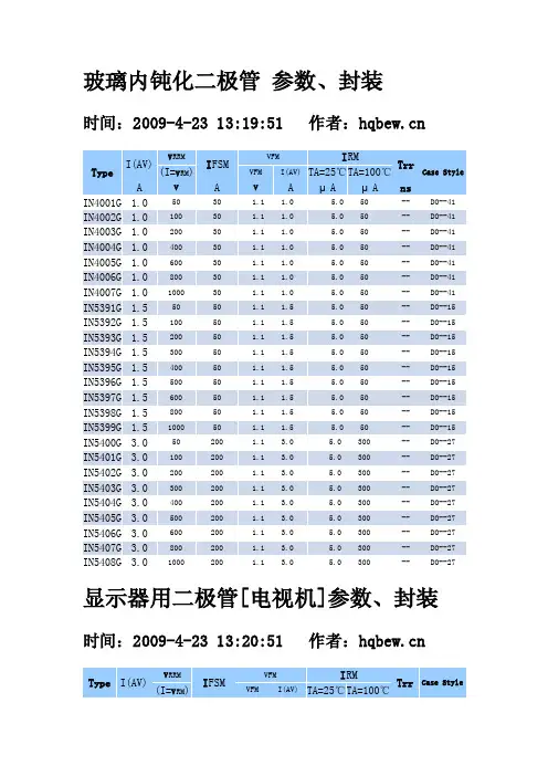
玻璃内钝化二极管参数、封装时间:2009-4-23 13:19:51 作者:Type I(AV)V RRMI FSMVFM I RMTrrCase Style (I=V RM) VFM I(AV)TA=25℃T A=100℃A V A V A μA μA nsIN4001G 1.0 5030 1.1 1.0 5.0 50--DO--41 IN4002G 1.0 10030 1.1 1.0 5.0 50--DO--41 IN4003G 1.0 20030 1.1 1.0 5.0 50--DO--41 IN4004G 1.0 40030 1.1 1.0 5.0 50--DO--41 IN4005G 1.0 60030 1.1 1.0 5.0 50--DO--41 IN4006G 1.0 80030 1.1 1.0 5.0 50--DO--41 IN4007G 1.0 100030 1.1 1.0 5.0 50--DO--41 IN5391G 1.5 5050 1.1 1.5 5.0 50--DO--15 IN5392G 1.5 10050 1.1 1.5 5.0 50--DO--15 IN5393G 1.5 20050 1.1 1.5 5.0 50--DO--15 IN5394G 1.5 30050 1.1 1.5 5.0 50--DO--15 IN5395G 1.5 40050 1.1 1.5 5.0 50--DO--15 IN5396G 1.5 50050 1.1 1.5 5.0 50--DO--15 IN5397G 1.5 60050 1.1 1.5 5.0 50--DO--15 IN5398G 1.5 80050 1.1 1.5 5.0 50--DO--15 IN5399G 1.5 100050 1.1 1.5 5.0 50--DO--15 IN5400G 3.0 50200 1.1 3.0 5.0 300--DO--27 IN5401G 3.0 100200 1.1 3.0 5.0 300--DO--27 IN5402G 3.0 200200 1.1 3.0 5.0 300--DO--27 IN5403G 3.0 300200 1.1 3.0 5.0 300--DO--27 IN5404G 3.0 400200 1.1 3.0 5.0 300--DO--27 IN5405G 3.0 500200 1.1 3.0 5.0 300--DO--27 IN5406G 3.0 600200 1.1 3.0 5.0 300--DO--27 IN5407G 3.0 800200 1.1 3.0 5.0 300--DO--27 IN5408G 3.0 1000200 1.1 3.0 5.0 300--DO--27显示器用二极管[电视机]参数、封装时间:2009-4-23 13:20:51 作者:Type I(AV)V RRMI FSMVFM I RMTrr Case Style (I=V RM) VFM I(AV)TA=25℃T A=100℃A V A V A μA μA ns10DF1 1.0 10030 1.0 1.0 5.0 100200DO--4110DF2 1.0 20030 1.0 1.0 5.0 100200DO--4110DF4 1.0 40030 1.2 1.0 5.0 100500do--4110DF6 1.0 60030 1.2 1.0 5.0 100500DO--4110DF8 1.0 80030 1.2 1.0 5.0 100500DO--4110ELS1 1.0 10030 1.1 1.0 5.0 100150DO--1510ELS2 1.0 20030 1.1 1.0 5.0 100150DO--1510ELS4 1.0 40030 1.2 1.3 5.0 100150DO--1510ELS6 1.0 60030 1.2 1.3 5.0 100150DO--1515DF4 1.0 40030 1.2 1.3 5.0 100150DO--4115DF8 1.0 80030 1.2 1.3 5.0 100150DO--411N4933 1.0 5030 1.3 1.0 5.0 100200DO--411N4934 1.0 10030 1.3 1.0 5.0 100200DO--411N4935 1.0 20030 1.3 1.0 5.0 100200DO--411N4936 1.0 40030 1.3 1.0 5.0 100200DO--411N4937 1.0 60030 1.3 1.0 5.0 100200DO--411N5059 1.0 20050 1.2 1.0 5.0 3001500DO--411N5060 1.0 40050 1.2 1.0 5.0 3001500DO--411N5061 1.0 60050 1.2 1.0 5.0 2001500DO--411N5062 1.0 80050 1.2 1.0 5.0 2001500DO--411S1834 1.0 40060 1.2 1.5 5.0 1001500DO--151S1835 1.0 60060 1.2 1.5 5.0 1001500DO--151S1885 1.0 10060 1.2 1.5 5.0 100--DO--151S1886 1.0 20060 1.2 1.5 5.0 100--DO--151S1887 1.0 40060 1.2 1.5 5.0 100--DO--151S1888 1.0 60060 1.2 1.5 5.0 100--DO--151S1941 0.5 10035 1.2 0.5 5.0 100--DO--151S1942 0.5 20035 1.2 0.5 5.0 100--DO--15显示器用二极管[电视机]参数、封装[2] 时间:2009-4-23 13:22:03 作者:Type I(AV)V RRMI FSMVFM I RMTrrCase Style (I=V RM) VFM I(AV)TA=25℃T A=100℃A V A V A μA μA ns1S1943 0.5 40035 1.2 0.5 5.0 100--DO--15 1S1944 0.5 60035 1.2 0.5 5.0 100--DO--15 1SS81 0.2 200 1.0 1.0 0.1 5.0 5050DO--35 1SS82 0.2 250 1.0 1.0 0.1 5.0 5050DO--3530DF1 3.0 100200 1.0 3.010 200200DO--2730DF2 3.0 200200 1.0 3.010 200200DO--2730DF4 3.0 400200 1.2 3.010 200400DO--2730DF6 3.0 600200 1.2 3.010 200400DO--2731DF1 1.6 100125 0.98 3.0 5.0 5030DO--2731DF2 1.6 200125 0.98 3.0 5.0 5030DO--2731DF3 1.5 300125 1.2 3.0 5.0 5030DO--2731DF4 1.5 400125 1.2 3.0 5.0 5030DO--273JH45 3.0 600200 1.3 3.010 100250DO--273JH61 3.0 600200 1.3 3.010 200500DO--273TH41 3.0 1500200 1.5 3.510 200800R--5AG01Y 1.0 10025 1.2 1.0100 50050DO--41AG01Z 0.7 20015 1.8 0.7100 50050DO--41AG01 0.7 40015 1.8 0.7100 50050DO--41AG01A 0.5 60015 1.8 0.5100 50050DO--41AK03 1.0 30250.55 1.0500 5000--DO--41AK04 1.0 40250.55 1.0500 5000--DO--41AM01Z 1.0 200250.98 1.010 50--DO--41AM01 1.0 400350.98 1.010 50--DO--41AM01A 1.0 600350.98 1.010 50--DO--41AU01Z 0.5 20015 1.7 0.510 150100DO--41AU01 0.5 40015 1.7 0.510 150100DO--41AU01A 0.5 60015 1.7 0.510 150100DO--41显示器二极管 [电视机]参数、封装[3] 时间:2009-4-23 13:22:54 作者:Type I(AV)V RRMI FSMVFM I RMTrrCase Style (I=V RM) VFM I(AV)TA=25℃T A=100℃A V A V A μA μA nsAU02Z 0.8 20025 1.3 0.810 250100DO--41 AU02 0.8 40025 1.3 0.810 250100DO--41 AU02A 0.8 60025 1.3 0.810 250100DO--41 BA157 1.0 40020 1.3 1.0 5.0 50300DO--15 BA158 1.0 60020 1.3 1.0 5.0 50300DO--15 BA159D 1.0 80020 1.3 1.0 5.0 50300DO--15 BA159 1.0 100020 1.3 1.0 5.0 50300DO--15 BAV18 0.25 60 3.0 1.25 0.20.1 10050*DO--35 BAV19 0.25 120 3.0 1.25 0.20.1 10050*DO--35BAV21 0.25 250 3.0 1.25 0.20.1 10050*DO--35 BAW62 0.25 75 1.0 1.0 0.1 5.0 100 4.0DO--35BY228 2.5 150050 1.6 2.5 5.0 1501000R--5BY228 2.5 150050 1.6 2.5 5.0 1501000R--5BY296 2.0 10070 1.3 2.010.0 100250DO--27BY297 2.0 20070 1.3 2.010.0 100250DO--27BY298 2.0 40070 1.3 2.010.0 100250DO--27BY299 2.0 80070 1.3 2.010.0 100250DO--27BY299 2.0 80070 1.3 2.010.0 100250DO--27BY299S 2.0 100070 1.3 2.010.0 100250DO--27BY396 2.0 10070 1.25 2.010.0 100250DO--27BY396 2.0 10070 1.25 2.010.0 100250DO--27BY397 2.0 20070 1.25 2.010.0 100250DO--27BY398 2.0 40070 1.25 2.010.0 100250DO--27BY399 2.0 80070 1.25 2.010.0 100250DO--27BY399S 2.0 100070 1.25 2.010.0 100250DO--27BY488 2.0 150070 1.25 2.010.0 100250DO--27 BYD31D 0.5 200 5.0 1.35 0.5 5.0 100250DO--41显示器二极管 [电视机]参数、封装[4] 时间:2009-4-23 13:24:05 作者:Type I(AV)V RRMI FSMVFM I RMTrrCase Style (I=V RM) VFM I(AV)TA=25℃T A=100℃A V A V A μA μA nsBYD31G 0.5 400 5.0 1.35 0.5 5.0 100250DO--41 BYD31J 0.5 600 5.0 1.35 0.5 5.0 100250DO--41 BYD31K 0.5 800 5.0 1.35 0.5 5.0 100250DO--41 BYD31M 0.5 1000 5.0 1.35 0.5 5.0 100250DO--41 BYD33D 1.3 20020 1.3 1.0 5.0 100250DO--15 BYD33G 1.3 40020 1.3 1.0 5.0 100250DO--15 BYD33J 1.3 60020 1.3 1.0 5.0 100250DO--15 BYD33k 1.3 80020 1.3 1.0 5.0 100300DO--15 BYD33M 1.3 100020 1.3 1.0 5.0 100300DO--15 BYM6C 6.0 400400 1.0 6.010.0 200--R--6 BYT52A 1.0 5060 1.0 1.0 5.0 200200DO--15 BYT52B 1.0 10060 1.0 1.0 5.0 200200DO--15 BYT52D 1.0 20060 1.0 1.0 5.0 200200DO--15 BYT52G 1.0 40060 1.0 1.0 5.0 200200DO--15BYT52K 1.0 80060 1.0 1.0 5.0 200200DO--15 BYT52M 1.0 100060 1.0 1.0 5.0 200200DO--15 BYT56A 3.0 5050 1.4 3.010 150100DO--27 BYT56B 3.0 10050 1.4 3.010 150100DO--27 BYT56D 3.0 20060 1.4 3.010 150100DO--27 BYT56G 3.0 40050 1.4 3.010 150100DO--27 BYT56J 3.0 60050 1.4 3.010 150100DO--27 BYT56K 3.0 5050 1.4 3.010 150100DO--27 BYT56M 3.0 100050 1.4 3.010 150100DO--27 BYV12 1.5 10060 1.3 1.5 5.0 50300DO--15 BYV13 1.5 40060 1.3 1.5 5.0 50300DO--15 BYV14 1.5 60060 1.3 1.5 5.0 50300DO--15 BYV15 1.5 80060 1.3 1.5 5.0 50300DO--15显示器二极管 [电视机]参数、封装[5] 时间:2009-4-23 13:24:55 作者:Type I(AV)V RRMI FSMVFM I RMTrrCase Style (I=V RM) VFM I(AV)TA=25℃T A=100℃A V A V A μA μA nsBYV16 1.5 100060 1.3 1.5 5.0 50300DO--15 BYV26A 1.0 20030 2.5 1.0 5.0 10030DO--41 BYV26B 1.0 40030 2.5 1.0 5.0 10030DO--41 BYV26C 1.0 60030 2.5 1.0 5.0 10030DO--41 BYV26D 1.0 80030 2.5 1.0 5.0 10075DO--41 BYV26E 1.0 100030 2.5 1.0 5.0 10075DO--41 BYV27-50 2.0 50500.98 2.0 5.0 10025DO--15L BYV27-100 2.0 100500.98 2.0 5.0 10025DO--15L BYV27-150 2.0 150500.98 2.0 5.0 10025DO--15L BYV27-200 2.0 200500.98 2.0 5.0 10025DO--15L BYV27-300 2.0 300500.98 2.0 5.0 10050DO--15L BYV27-400 2.0 400500.98 2.0 5.0 10050DO--15L BYV27-400 2.0 40050 1.05 2.0 5.0 10050DO--15L BYV27-600 2.0 60050 1.25 2.0 5.0 10050DO--15L BYV37 2.0 80075 1.3 2.010 100200DO--15L BYV38 2.0 100075 1.3 2.010 100200DO--15L BYV95A 1.5 20035 1.6 3.0 5.0 150250DO--15 BYV95B 1.5 40035 1.6 3.0 5.0 150250DO--15 BYV95C 1.5 60035 1.6 3.0 5.0 150250DO--15BYV96E 1.5 100035 1.6 3.0 5.0 150300DO--15 BYW32 2.0 20040 1.2 2.0 5.0 50200DO--15 BYW33 2.0 30040 1.2 2.0 5.0 50200OR BYW34 2.0 40040 1.2 2.0 5.0 50200OR BYW35 2.0 50040 1.2 2.0 5.0 50200OR BYW36 2.0 60040 1.2 2.0 5.0 50200DO--15L BYW72 3.0 20060 1.1 3.0 5.0 50200DO--27 BYW73 3.0 30060 1.1 3.0 5.0 50200DO--27。
FOSC 400 A8 B8光纤接缆闭合设备说明书

FOSC 400 A8/B8ClosureI N S T A L L A T I O N I N S T R U C T I O NFor Fiber Optic Splices, Taps, and Drops1.0 General Product DescriptionThe FOSC 400 A8/B8 ber optic closure is environmentally sealed using heat-shrinkable sleeves with hot-melt adhesives. The FOSC 400 A8/B8 closure can also be cold-sealed for above-grade applications. This closure can be direct buried or installed inmanholes, hand holes and aerial locations. The FOSC 400 A8/B8 closure has one oval port for two cables or a mid-span cable entry,and eight small round ports. The individual drop port approach simpli es the provisioning, repair, and restoration of subscriber services.Cable blocking is not recommended due to space constraints.The maximum single splice capacity is 96, with 24 splices stored on four trays. The maximum mass fusion splice capacity is 216,using three trays with six splices per tray. The FOSC 400 A8/B8 closure can house pre-con gured splitters as well as up to fou r adapters in a specially modi ed “bulkhead” basket. A standard slack basket must be used to store ribbon slack. Loose bu er tubes can be stored in a standard storage basket or in a storage sock. The sock can be positioned along under the trays or under the slack basket, if both are necessary. For the FOSC 400 B8 closure, a slightly larger sock area accommodates loop-through of 144- ber midspan cable.2.0 Kit Contents•Dome •Clamp •O-Ring •Base•Oval port cable seal•2 Pieces of aluminum tape •Branch-o clip •Cleaning tissue•Abrasive strips •2 Bond wires (optional) •Slack storage sock•Basket with or without bulkhead (baskets are optional) and mounting screws•FOP Tubing•Transportation tubing (standard and ribbon sizes)•Ribbon spiral wrap•Loose bu er tube wrap •Small white tie wraps •Identi cation labels •Velcro fastener with tray holding clip •Tray support bracket and 2 screws •Installation Instructions Tray Kit (optional):•1 standard tray with cover •Small white tie wraps*Use SMOUV-1120-01-US splice protection sleeves with SM12 modulesOrdering Information FOSC 400-A8 - bb - c - d e f or FOSC 400-B8 - bb - c - d e f bb:Tray Type12 = with tray, 2 SM6 splice modules 16 = with tray, 2 SM8 splice modules 24 = with tray, 2 SM12 splice modules*NT = No traysc:No. of Trays Pre-installed0 = no tray (standard)1 = one trayd:Basket typeN = none (includes storage sock)A = with basket (limit 3 trays)B = with basket (limit 3 trays)P = with bulkhead basket (limit 3 trays)T = with tall basket (limit 2 trays)e:Ground Feed-through Lugs G = with grounding N = nonef:Valve for ash testing V = valved3.0 Technical Product InformationDimensions and Capacities FOSC 400 A8 Closure FOSC 400 B8 ClosureDiameter7 inches (including clamp)7 inches (including clamp)Length16 inches (top of dome to end of port)21 inches (top of dome to end of port)Splice Capacity96 splices96 splicesTray Capacity 4 A-size trays (3 trays with installed basket) 4 A-size trays (3 trays with installed basket)8 slim trays (6 slim trays with installed basket)8 slim trays (6 slim trays with installed basket) Slack Storage Capacity Up to 600 linear inches of 3mm diameter loose Up to 756 linear inches of 3mm diameterbuffer tube (Standard midspan of 72" +/- 3", loose buffer tube cable (Standard midspan ofusing 96 fiber count cable)72” or 63” using 144-fiber cable)Oval Port0.4'' to 1.0'' cable diameter0.4'' to 1.0'' cable diameterRound Ports0.2'' to 0.4'' cable diameter0.2'' to 0.4'' cable diameterSplittersThe FOSC 400 A8 or B8 closure will accommodate the FOSC OC 6 splitter, with capacity as follows:Splitter size Splitter type Description Max per closureFOSC-OC-6A11400 3 1x4 FBTFOSC-OC-6A11800 2 1x8 FBTFOSC-OC-6P11G00 2 1x16 PlanarFOSC-OC-6P11W00 1 1x32 PlanarAccessory KitsKit Name DescriptionFOSC-ACC-A-TRAY-12A-size splice tray with 2 SM6 splice modulesFOSC-ACC-A-TRAY-16A-size splice tray with 2 SM8 splice modulesFOSC-ACC-A-TRAY-24A-size splice tray with 2 SM12 splice modulesFOSC-ACC-B-TRAY-12B-size splice tray with 2 SM6 splice modulesFOSC-ACC-B-TRAY-16B-size splice tray with 2 SM8 splice modulesFOSC-ACC-B-TRAY-24B-size splice tray with 2 SM12 splice modulesFOSC-AS-TRAY-S6-1Slim tray with 6 splice capacityFOSC-ACC-A8/B8-CABLE-SEAL Round port heat-shrink seal kitFOSC-ACC-A8-BASKET Slack storage basketFOSC-ACC-A8-ADP-BASKET Slack storage basket w/bulkheadFOSC 450 A TALL BASKET Tall slack storage basketSC RETAINER Retainers for installing up to 4 SC adapters in bulkhead basketFC RETAINER Retainers for installing up to 4 FC adapters in bulkhead basketST RETAINER Retainers for installing up to 4 ST adapters in bulkhead basketFOSC-ACC-LASHING-STRAPS Kit for lashing closure directly to an aerial strandFOSC-ACC-UNIV-AERIAL-CLMP Kit for offset mounting closure to an aerial strandFOSC-ACC-WALL/POLE-MOUNT Kit for mounting closure to a wall or a poleFOSC-ACC-WORK-STAND Optional work standFOSC-ACC-CV-1981-110V110V Heat gun with reducer tip for installing hot air cable sealsFOSC-ACC-CV-1981-220V220V Heat gun with reducer tip for installing hot air cable sealsFACC-HEAT-GUN-TIP-01Heat gun tip for installing small round port sealsFOSC-ACC-BOND-CLAMP-5.5Alligator bond clamp with #8 wire and hooked eyeletsSMOUV-1120-01-US62mm long single fusion splice protection sleevesSMOUV-1120-02-US42mm long single fusion splice protection sleevesFOSC-ACC-A-PED-MTG-BKT Kit for mounting in pedestalFOSC-ACC-A8-PORT-CONE Pack of 8 cones for cold sealingFOSC-ACC-A8-PORT-CONE-BP Bulk pack of 20 cones for cold sealing4.0Installation Instructions4.1Remove Dome/Base Seal1.Push the handle to the side to release the pin from the notch, then lift the handle.See Figure 1 Step 1.2.Hook the “feet” of the handle behind the two posts and pry open one half of theclamp. See Figure 1 Steps 2 and 3.3.Open the handle fully. Pull the other half of the clamp to release it from thedome.4.Support the dome before removing the clamp. Remove dome and O-ring. HangO-ring on top of dome.5.Protect dome from dirt during installation. DO NOT SIT ON DOME!6.Place the base in the work stand.4.2Install Basket (optional)Follow these steps to install the FOSC-ACC-A8-BASKET or FOSC-ACC-ADP-BASKET (bulkhead basket) slack storage baskets on the FOSC 400 A8 or B8 closure tray bracket.1.Holding the basket open side up (like the splice trays), insert the tab of the basketthrough the slot in the tray bracket. (Figure 2)2.Insert two screws (supplied with basket) through the holes in the bottom of thebasket, and through the corresponding two holes in the tray bracket. Tightenscrews completely. (Figure 3)3.For the bulkhead basket, snap plastic retainer clips into bracket.4.3Install Standard Tray Kit (optional)If no trays have been factory-installed in the kit, the tray kit must be installed. Additional trays can be installed at any time. The procedure differs slightly, depending upon the presence or absence of a basket:4.3.1Tray Kit Installation With a Basket in PlaceWith the closure right side up, insert the FOSC 400 A or B closure tray in the second slot of the tray bracket. Insert one tray pin in the tray bracket first, then pivot the tray to pop the second pin into place.4.3.2Tray Kit Installation With No Basket Installed1.With the closure right side up, insert the FOSC 400 A or B closure tray in thelowest slot of the tray bracket. Insert one tray pin in the tray bracket first, thenpivot the tray to pop the second pin into place. (Figure 5)2.Holding the tray in place, turn the closure over exposing the bottom of the trayholder.3.Install the tray bracket under the bottom tray with the two supplied screws. Usethe shiny, bright-finish screws; the larger, duller screws are for use with otherclosures. See Figure 6.4.4Install Tray for Pedestal Mount Without BasketWith the closure right side up, insert the FOSC 400 A or B closure tray bottom side up in the lowest slot on the tray bracket. Insert one tray pin in the tray bracket first, then pivot the tray to pop the second pin into place.Fig. 2 Fig. 3Fig. 5 Fig. 4 Fig. 64.6Prepare CablesNote: The maximum midspan length recommendations listed in Table 1 (below) will be limited with higher count loose buffer tube (LBT) cable. The recommended fiber count is 96 for a midspan cable entry. For midspan cable entries, it is recommended to find the reverse oscillation in the buffer tubes and measure 36” in each direction.4.5Install Tray for Pedestal Mount With BasketWith the closure right side up, insert the FOSC 400 A or B tray bottom side up in the second slot of the tray bracket. Insert one tray pin in the tray bracket first, then pivot the tray to pop the second pin into place. (Figure 7)Note: For routing, refer to Section 4.7.Fig.7Fig. 12Fig. 13Fig. 14Fig. 15Fig. 116.When routing de-ribbonized fibers directly to the tray, cut the core tube 1'' from the ring cut and extend with spiral or transportation tubing.7.De-ribbonize the ribbon near the base and use transportation or spiral tubing to protect the fibers as they are routed onto the trays.Mark TubeLBT WrapFig. 16Fig. 19Fig. 24Fig. 22Fig. 23Fig. 20Fig. 214.10 Seal Cables in Oval PortNOTE: For instructions on sealing drop cables in the round ports, refer to the installation instructions included with the round port sealing kit.1. Clean the port and 8’’ of the cable sheath beyond the port edge with the supplied cleaning tissue.2. Abrade the port and 8’’ of cable with the supplied abrasive strip, and remove any abraded material from the port with a clean dry cloth.3. Slide the port seal up against the base and mark the cables at the end of the seal.4. Slide the tube back off the port. (Figure 20)5.Wrap each cable with aluminum tape by placing the blue stripe over the line made on the cable. (Figure 21)Note: Make sure the longer side of the tape is facing away from the sleeve. The aluminum tape is used to protect the outer sheath only and not for sealing. 6. Slide the tube up against the base.7. Place the yellow branch-off clip between the two cables. Place a cable tie around both cables at the end of the aluminum tape. (Figure 22 and 23)8.With the FOSC CV1981 heat gun set on 10, begin heating the port sleeve at the base, shrinking a one inch strip around the port. Direct the air around the sleeve until the green paint turns dark brown.9.Let cool for 15 seconds and continue heating the remainder of tube evenly until it has completely conformed to the cables. (Figure 23)The seal is completely installed when:•Melted adhesive appears at the cable end (Red from the tube & yellow from the branch off clip).•All green thermochromic paint on the seal is dark brown.Note: Using heat gun reducer tip FACC-HEAT-GUN-TIP-01 will help reach interior spaces between ports when shrinking multiple round port seals.4.11Organize and Splice Fibers1.Always begin splicing with the bottom tray. Install trays as you go. Hinge the upper trays and secure them out of the way, using the plastic holder on the Velcro fastener to place between the tray hinges. (Figure 24)2. Remove all stored un-spliced fibers from the tray.3.Arrange the fibers around the outside of the tray or in a circular pattern by follow-ing the designated routing arrows on the tray. Lay the fibers to be spliced in the tray to see how they will fit when spliced. Plastic tabs are included with the trays to help hold down the stored fibers.4.Refer to routing diagrams on page 7 for various fiber/splice configurations.5. Trim fibers as necessary and splice per locally approved practices.6.Begin storing the splices on the outside of the splice modules and work toward the middle. Store the splices on the tray one at a time, or remove the splice module from the tray, fill it, and snap the filled splice module into the tray.Note: Pull slack ribbon back into storage basket after splicing. See Ribbon Routing diagram, page 7.7. When all splices are completed and stored, replace the tray covers.8.Secure all trays to the bottom tray or basket with the Velcro fastener. (Be sure to put the tray holder back on the Velcro fastener.)Fig. 26Fig. 27Fig. 284.13 Test Seals (Kits with Valves Only)Ensure that all heat-shrinkable parts are cool to the touch.Pressure-test the closure with no more than 5 psi. Thoroughlysoap all seals and the valve to check for seal integrity.Important: After flash testing, bleed all pressure from theFOSC 400 A8 closure through the valve.4.14 Mount ClosureAfter the closure has been successfully tested, mount it forstorage. The following kits provide appropriate hardware formounting the closure in various applications:FOSC-ACC-LASHING-STRAPS Kit for lashing closuredirectly to an aerial strand(Figure 26)FOSC-ACC-UNIV-AERIAL-CLMP Kit for offset mountingclosure to an aerialstrand (Figure 27)FOSC-ACC-WALL/POLE-MOUNT Kit for mounting closureto a wall or a pole (Figure 28)FOSC-ACC-A-PED-MTG-BKT Kit for mounting closure inpedestal. (Fig 29)Fig. 2911©2005, 2016 C o m m S c o p e I n c . P r i n t e d i n U S A P M L F 77981 F 456.09/05FOSC 400 is a trademark of CommScope Inc.12Technical Assistance Center (TAC)Tel.: 800.830.5056Email:************************** The information given herein, including drawings, illustrations and schematics which are intended for illustration purposes only, is believed to be reliable. However, CommScope makes no war-ranties as to its accuracy or completeness and disclaims any liability in connection with its use. CommScope’s obligations shall only be as set forth in CommScope’s Standard Terms and Conditions of Sale for this product and in no case will CommScope be liable for any incidental, indirect or consequential damages arising out of the sale, resale, use or misuse of the product. Users of CommScope products should make their own evaluation to determine the suitability of each such product for the speci c application.。
大连数控18Ti 操作说明书

3.7 附录 ......................................................................................................................... 31
3.7.1 报警一览表 ....................................................................................................... 31
18Ti 操作说明书
大连高金数控有限公司 2008 年 12 月
1
18Ti CNC 资料---操作说明书手册 1 简介 .................................................................................................................................. 1
I
18Ti CNC 资料---操作说明书手册 4.4 伺服参数 .................................................................................................................. 50
3.3.1 操作步骤........................................................................................................... 25
3.3.2 MDI 运行.......................................................................................................... 27
Extech CD Regulated Power Supply Modelos 382203 y
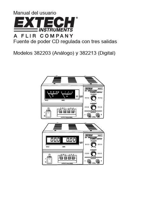
Manual del usuarioFuente de poder CD regulada con tres salidas Modelos 382203 (Análogo) y 382213 (Digital)IntroducciónFelicitaciones por seleccionar la Fuente de poder CD regulado Modelos 382203 (análogo) o 382213 (digital) de Extech. Los modelos 382203 y 382213 son fuentes de poder reguladas de estado sólido y compactos, apropiadas para muchas aplicaciones incluyendo pruebas de banco, servicio de campo, equipo de telecomunicaciones y diversión.Descripción del medidor1. Pantallas LCD Voltaje y Corriente2. LED indicador de estado de límite de corriente3. Interruptor de encendido con LED de estado4. Terminales de salida 5V y 12V fijo5. Terminales de salida alimentación variable6. Perillas de ajuste de voltaje y corriente variableNota: El Modelo 382213 (escalas LCD) se muestra arriba. El Modelo 382203 (mostrado en la portada) usa escala análoga.Operación1. La Fuente de poder debe ser alimentada con voltaje de línea nominal (110V ó 220V) dentro de+ 5%.2. Antes de encender, retire todas las cargas conectadas y fije la perilla de ajuste de voltajetotalmente contrarreloj (salida 0V CD).3. Para operar la fuente de alimentación como fuente de corriente constante, la salida de corrientedebe fijarse entre 10% y 100% del valor nominal (3A). El indicador de limitación de corriente se iluminará al activarse el circuito limitador de corriente.4. Use las perillas para ajuste de corriente y voltaje para fijar las salidas variables de corriente yvoltaje respectivamente. Use las terminales de salida variable para conexiones.5. Para las salidas de 5VCD y 12VCD, use las terminales de salida fija.6. Las pantallas análoga o digital indicaran las salidas reales de corriente y voltaje.7. Mantenga libre de obstrucciones las rejillas de ventilación del medidor (arriba y lados) paraprevenir sobrecalentamiento.Especificaciones382203382213Indicador Análogo doble conescalas Pantalla LCD doble de 3dígitosSalida de voltaje, CD0-30VSalida de corriente, CD0 - 3 amperiosIndicador de límite decorrienteLED de estadoPrecisión ± 7% de la escala total ± 1% de la escala total + 2dígitosOndulación y Ruido< 5mVRegulación de línea< 0,05% + 10mVVoltaje fijo de salida5V / 0,5A (Continuo); 1A (máx.)12V / 0,5A (Continuo); 1A (máx.)Tensión110/220VCA 50/60Hz (conmutable) Dimensiones152 x 142 x 242mm(6 x 5,6 x 9,5") (WxHxD)Peso4,5 kg (10 lbs.)Copyright (c)2012 Extech Instruments Corporation (a FLIR company) Reservados todos los derechos, incluyendo el derecho de reproducción total o parcial en cualquier medi o.。
TRAUB产品简介

Product OverviewContentsCNC Universal T urning Machines TNA 68CNC T urn Mill Center TNX CNC Sliding Headstock Automatics TNL 10Automation Components 20Control Systems 2223Programming Programming Stations 24Product Training 25At TRAUB we consider it to be our foremost duty to serve our customers.TRAUB achieved its reputa-tion as one of the leading manufacturers of CNC turning and machining centres not only by having gained a headstart in matters of advanced technology and excellence,but also through the development of a user-orientated product range and an extensive service network.This brochure is designed to provide youwith a brief introduction to our competitive range ofmachine tools.CNC UniversalT urning MachinesT echnical Data TNA300 TNA400 TNA500 TNA600 Bar capacitiy mm (in) 65 (2.6) 80 (3.2) 80 (3.2) 100 (3.9) Spindle nose DIN 55026 A6 A8 A8 A11 Chuck diameter mm (in) 200/225 (7.9/8.9) 250/340 (9.8/13.4) 315 (12.4) 400 (15.7) Turning length max.mm (in) 450 (17.7) 750 (29.5) 1000 (39.4) 1000 (39.4) Main drive kW (hp) 11 (15) 22 (30) 31 (42) 37 (50) Spindle speed max.rpm 4000 3150 2800 2800T ool carrier/stations 1/12 1/12 1/12 1/12OT ailstock ●● OOC-axis O O OY-axis O O ––Drives for rotating tools O O O O CNC control TX8i TX8i TX8i TX8iCNCT urn Mill CenterT echnical Data TNX65/42Bar capacity main /counter spindle mm (in) 42 (1.7) 65 (2.6)Spindle nose ISO 702/1A5 A6Drive main /counter spindle kW (hp) 28 (37.5) 24 (32.2)Speed main/counter spindle max. rpm70005000Chuck diameter mm (in) 160 (6.3) 175 (6.9)T urning length max. mm (in) 650 (25.6) 650 (25.6)T ool carrier /stations max. 4/404/40T ool carrier design T urret, Milling spindleDrives for rotating tools ● ●C-axis, B-axis O O Y -axis● ●CNC controlTX8i-sTX8i-sThe TNX65/42 provides an economic solution for your applications with 2, 3 or 4 turrets. The combination of two turrets with a milling spindle offers more power and torque for drilling and milling operations.The machine concept of the TNX65/42 has been matched to the diverserequirements of the workpieces. In addition, if offers a large number of advantages, e.g. quadruple functional symmetry, i.e. four identical turrets with an independent Y axis (option), having the same spaces for tool change and an identical number of tool stations, as well as free allocation of the tool carriers to the two spindles. The TNX65/42 guarantees optimal cutting power by powerful drives on main and counter spindle and powerful tool drives on all turrets for perfect completemachining.CNC SlidingHeadstock AutomaticsAxes and directions of theTNL12.T echnical Data TNL12 TNL12KBar capacity main /counter sp. mm (in) 13 (15) (0.5/0.6) 13/16 (0.5/0.6)Guide bushing● – T urning length 1 stroke max. mm (in)130 (5.1)50 (2) Programmed guide bushingO – Main drive kW (hp) 3.15 (4.2)3.15 (4.2) Spindle speed max. rpm 12000 12000 T ool carrier/stations 4/20 4/20 C-axisO O Drives for rotating tools O O End working attachment O O Rear end machining unit O O Y -axis R1 ● ● T urret 2 with Z-axis (50 mm / 2 in)O O CNC controlTX8iTX8iParts of range of the TRAUB CNC sliding headstock automaticTNL12.Headstock AutomaticsT echnical DataTNL18Sliding headstock / Single spindle bar automaticBar capacity main /counter spindle mm (in) 18/20 (0.7/0.8)Guide bush /Guide sleeve ●/●Z1 travel max. mm (in) 205 / 80 (8.1 / 3.1)Main drive kW (hp) 5,5 (7.4)Spindle speed max. rpm 12000 T ool carrier /-places 3 / 52C-axis●Drives for rotating tools ●B-axis ORear end machining unit ●Y -axis upper / lower ●/● T ool carrier with Z-axis upper / lower●C controlTX8i-sParts of range of the TRAUB CNC sliding headstock automatic TNL18.Axes and directions of the TNL18.Headstock AutomaticsT echnical DataTNL18PSliding headstock / Single spindle bar automaticBar capacity main /counter spindle mm (in) 20 (0.8)Guide bush / Guide sleeve●/●Z1 travel max.mm (in) 205 / 80 (8.1 / 3.1)Main drive kW (hp) 3,7 (5.0)Spindle speed max. rpm10000 T ool carrier /-places 3/52 C-axis● Drives for rotating tools ●Rear end machining unit ●Y -axis lower● T ool carrier with Z-axis lower ● CNC controlTX8i-pAxes and directions of the TNL18P .CNC SlidingHeadstock AutomaticsT echnical DataTNL32Sliding headstock / Single spindle bar automaticBar capacity main /counter spindle mm (in) 32 (1.3)Guide bush / Guide sleeve ● / ●Z1 travel max. mm (in) 305 (12) / 127 (5)Main drivekW (hp) 10.7 (14.4) Spindle speed max. rpm 8000 T ool carrier /stations 3/67 C-axis●Drives for rotating tools ●Rear end machining unit ●Y -axis upper / lower ●/●T ool carrier with Z-axis upper / lower●CNC controlTX8i-sAxes and directions of theTNL32.CNC SlidingHeadstock AutomaticsT echnical Data TNL32PSliding headstock / Single spindle bar automaticBar capacity main /counter spindle mm (in) 32 (1.3) Guide bush / Guide sleeve ● / ● Z1 travel max.mm (in) 305 / 125 (12 / 4.9)Main drive kW (hp) 10.7 (14.4)Spindle speed max. rpm 8000 T ool carrier /stations3/67C-axis ● Drives for rotating tools ● Rear end machining unit ● Y -axis lower ●T ool carrier with Z-axis lower●CNC controlTX8i-pAxes and directions of the TNL32P.2120Automations ComponentsCNC Bar Loading Magazines Single bar feeder and short bars magazines as well as supplier’s makes on request.It is our pleasure to advice you on your automation and production plant requirements. For all TRAUB turning machines we supply complex manufacturing systems and their control components or magazine attachment tailored to suit your particular needs.T ypeBar DiameterBar LengthsMachine Typemm(in) mm (ft)DNH 42 6 - 42 (0.2-1.7) 3000 / 4000 (9.8/13) TNX DNH 61 10 - 63 (0.4-2.5) 3000 / 4000 (9.8/13) TNA, TNXGantry Loader and Flexible Handling Systems SystemMachine TypeMax. Workpiece Weightkg (lbs) UHS TNX42/6510 (22)Schematic representation of the TRAUB DNH bar loading magazine.The roller guides support the bar safely.Degree of utilization considerably increased by the fl exible handling systems forchuck and shaft parts with TRAUB UHS.ProgrammingTRAU B WinCNC-OS Operating system for TRAUB machines.TRAU B WinFlexIPS /WinFlexIPS PlusFlexible, windows-based workpiece-oriented graphic programming system.– Stepwise parallel program-ming and simulation– Extremely simple synchroni-zation of machining sequences including up to 4 subsystems – Floor-to-fl oor time optimization already during programmingNetwork Connection EthernetTRAUB PolyformSoftware for milling operations using CNC turning centers.TRAUB Software Modules Further a substantial number of modules for programming support, e.g.:WinGravur (Engraving), WinCom, WinSynchro, WinCAD.64 bitHigh-Performance Control SystemsT echnical Data TX8i / TX8i-s / TX8i-p Programming EIA, ISO Min. input / output increment – X, Y, Z, R, V-axes mm 0.001– Resolutions mm 0.0001– C-axisDegree 0.001Rapid traverse rate 1) max. m/min 480Max. thread pitch mm 999.999Max. radius99999.999Tool correction offset pairs to 4 x 80Block changing time ms < 3,5Position control cyclems0.341)Realized rapid traverse dependent on machine.2524Y our automatic lathe becomes more productive when opera-ted by well-trained employees. So TRAUB offers professionel courses for qualifying and educating your employees and thus increasing their effectivity. In our up-to-date training cen-ter we impart a practical and comprehensive know-how in operation and programming of our lathes.Y our benefi t at a glance:– Detailled information on the latest CNC turning technology– Effi cient training and edu-cation of your employees – Better product quality by optimum knowledge of the setting parameters – More productive and cost-effi cient operation of the TRAUB machinesProgramming Stationsthe real machine– 3D simulation and computed control give increased safety TRAU B Workshop and Factory Organization TRAUB offers numerous aids for the machine environment, e.g.– proDNC – TOP– Production- and machine data acquisition (TRAUB MDM).TRAUBProgramming Stations Software modules for pro-gramming support are availab-le for a PC-work station.– WinCNC – WinFlexIPS – WinFlexIPS PlusTRAU B WinFlexIPS Plus – Planning and optimization of the setup procedure using the manual mode and auto-matic mode functions as withProduct TrainingNotesTRAUB Drehmaschinen GmbH & Co.KG Hauffstraße 473262 Reichenbach,Germany Tel. +49 (7153) 502-0Fax +49 (7153) 502-694 www.traub.de 0 2 . 1 2 -7 1 5 / 1 A D P r i n t e d i n G e r m a n y S u b j e c t t o c h a n g e w i t h o u t p r i o r n o t i c e。
Easy Start 364 (3 ton) Soft Starter 368 (6 ton) So
Easy Start364 (3 ton) Soft Starter368 (6 ton) Soft StarterInstallation ManualMicro Air Corporation Phone (609) 259-2636 124 Route 526. Allentown NJ 08501 Fax (609) 259-6601Retrofit Instructions1.Read and understand these instructions completely before proceeding.2.Improper wiring can result in damage to EasyStart or connected components including but not limited towiring, compressors, and capacitors. Micro Air Corp is not responsible for damages to any of theaforementioned equipment caused by improper wiring.3.Turn off the breaker for the compressor’s electrical system.4.Consult the manufacture’s installation manual and wiring diagram for the identification of the following:a.Start capacitor (typically in a plastic can), start relay, or compressor start device. Note that thesedevices may NOT be installed on some systems.b.Run capacitor (typically in a metal can). Most have 2, multi-point terminal connections (orclusters). Some have 3 terminal connections.c.Control board switched-L1 output or main contactor compressor L1 output connecting to thecompressor common terminal (C) wire. Note some systems utilize a contactor to switch power tothe compressor, other use a power relay integrated into the main control board.5.If the system utilizes a start capacitor with a start relay, or a start assist device, disconnect all the wiringconnected to the start capacitor or the start assist and remove them from the electric box. Be aware thatsome connections to the compressor (e.g. compressor common L1 and compressor Run L2) may havejunction connections at terminals of the start relay. Therefore, it is best to NOT remove the start relayunless you are able to trace out these wiring junctions and splice them. Disconnecting and removing only the start capacitor from a system with a start cap and start relay will effectively disable the start relay, thus eliminating the need for it being removed.6.Locate the compressor run capacitor. Locate the wire connected from the run capacitor to the compressorrun winding terminal (R), and disconnect it from the run capacitor. Connect (splice) the brown wire from EasyStart to the disconnected wire.7.Connect the white wire from EasyStart to the same terminal of the run capacitor from which youdisconnected the (white) run winding (R) wire in step 6 above.8.Connect the orange wire from EasyStart to the terminal on the run capacitor that connects to thecompressor start winding terminal (S). If the run capacitor is a dual, compressor/fan type, make sure tochoose the correct capacitor terminal, typically labeled “COMP”, “C”, Herm, or “H”.9.Connect the black wire from EasyStart to the switched-L1 connection emanating from the main controlboard or main contactor that typically has a black or purple wire that connects to the compressor common(C) terminal wire.10.Wiring is now complete. Remove any remaining unused or disconnected wires and close all open electricalboxes and panels.11.Securely mount the EasyStart using the four holes provided on the mounting flange, locating it close to theoriginal system electric box (limited by wire harness length).12.Turn on the system circuit breaker using shore power. Start a heating or cooling cycle with the thermostat.13.EasyStart will now learn the characteristics of the compressor for the next five starts. This operation will bedone during normal operation and does not require any intervention or special actions. Once the learning process is completed, the EasyStart can be operated on either shore or generator power. During the learning starts, be sure to allow enough off time between starts for pressures to equalize. Equalization occurs in most systems within five minutes so we advise waiting at least five minutes between starts.IMPORTANT INSTALLATION NOTE FOR CRUISAIR® MARINE CUSTOMERS ONLY: When installing EasyStart into 230V SMX control applications that use the triac to switch power to the compressor, it is necessary to replace the triac with a relay. If the triac is not replaced, the pump relay triggers may suffer damage and ultimately fail. Please notr that this is not required for 115V SMX applications and the triac is still safe to use. See the Microair Webstore or contact Microair for details on the appropriate relay.Example EasyStart Installation Wiring Diagram:Jumper Usage:A six pin diagnostic header is located inside the EasyStart box. Most installations will not need to access this header.Jumpers may be placed on JP1 for certain special functions. Place jumpers only asshown below.Normal:Most operation should be done without a jumper installed on JP1 or with the jumperinstalled across pins 3 and 4 as shown.Default:A compressor may be operated with a factory defined start characteristic. This maynot be the optimal start for the connected compressor and is generally used for factorydiagnostics. No optimization is done with this setting.Relearn:If a compressor, start capacitor, or run capacitor is replaced, place a jumper onpins 4 and 6 as shown. Cycle power on then off again and replace the jumper in the “Normal”position. Follow step 13 of the retrofit instructions to complete the relearn process.Disable:This setting disables the microprocessor on the board so no operation can occur. Anti-Short Cycle Timer:EasyStart models incorporate a timer that prevents immediate restarts.This feature was added to prevent overheating of the start capacitor and reducefaults due to un-equalized pressures in the system. Restart will take up to 5minutes if power is removed then reapplied.Later models include a wire jumper JP2 (see picture on right) that canbe cut to eliminate this feature. System controls must be sufficient to prevent short cycling if this jumper is cut. Warning: Starts must be limited to 1 start every 5 minutes with pressures equalized if JP2 is cut.EasyStart Troubleshooting:Wiring Evaluation:A ll start components from the original installation are removed including PTC’s and startcapacitors.The Brown wire from EasyStart connects directly to the compressor run winding.The Black wire from EasyStart is spliced to the thermostat relay feeding the compressor overloadprotector on the compressor common terminal.The Orange wire from EasyStart is connected to the compressor run capacitor on the same side asthe compressor start winding.The White wire from EasyStart is connected to the AC-L2 or AC-N side of the compressor runcapacitor.Trouble Lights:Three diagnostic lights are provided inside the EasyStart box on the printed circuit board. These lights are labeled in white silkscreened letters next to the light. When a fault is detected, EasyStart willilluminate one or more lights to indicate which fault occurred. All faults except over current will reset after3 minutes. Over current is reset by removing power from EasyStart and reapplying power. Users will notnormally need to view these lights. The chard below defines the lights that are turned on for each fault.Fuses:Protection fuses are installed in the start circuit to prevent damage due to miswiring or start capacitorfailure. If this fuse fails in normal operation, there is most likely a problem with the start capacitor which should be replaced along with the fuse.364 (3 ton)1.Revision H and earlier boards: These boards incorporate a non-replaceable fuse inthe start circuit. These units must be returned to Microair for repair.2.Revision I and above boards: These boards incorporate a replaceable 15A 250Vrated, slow blow, 5mm x 20mm glass fuse.368 (6 ton)1.Revision E and earlier boards: These boards incorporate a non-replaceable fuse inthe start circuit. These units must be returned to Microair for repair.2.Revision F and above boards: These boards incorporate a replaceable 30A 250VACrated 3AB, 3AG, ¼” x 1 ¼” (6.35mm x 31.75mm) slow blow ceramic fuse.FAQ:What is re-learning?The re-learning process simply clears the EasyStart memory and returns it to as shipped condition. EasyStart should be re-learned whenever a compressor is changed or if pressures were not allowed to equalize during the learning process.To re-learn EasyStart, remove power and open the EasyStart box. Locate the 6 pin header shown in the jumper usage section of this manual and place the shorting jumper over pins 4 and 6 as shown. Start a cycle with your thermostat with the compressor powered from AC mains and allow EasyStart to start the compressor. Remove power once the compressor starts and replace the jumper to the stored position over pins 3 and 4. Replace the cover on EasyStart and complete at least 4 additional starts. Be sure to allow time for pressures to equalize between starts, usually 3 to 5 minutes.Be sure to remove the jumper from pins 4 and 6 and replace it to pins 3 and 4 immediately after the FIRST start and after power is removed.I connected everything and it just won’t start. What do I do now?First, do the wiring evaluation in this section. Wiring should be exactly as shown in the sample diagram with no left over start components. If there are any questions about wiring your unit, you can send a wiring diagram for your compressor to **************** along with your question.Be sure you are only using regular AC line power and not a generator or inverter for the first five starts. The first starts on EasyStart are usually higher than the final start and can overload marginal supplies and prevent EasyStart from learning the best start for your compressor.Check for any trouble lights. If any are illuminated, identify the reason EasyStart is not starting your compressor. Most times trouble lights point to a problem with the wiring.What does a “S talled” indication from EasyStart mean?Stalled means EasyStart is not seeing the condition where it can declare that the compressor is running and connect the compressor directly. The first thing to do is the wiring evaluation above.Stalled can also be caused by an improperly sized or bad start capacitor. 3T systems with 220 volt 12K BTU and smaller compressors may require smaller value start capacitors. Contact Microair prior to purchase to determine requirements for these systems.What d oes “Power Interruption” mean?Power was lost for several AC cycles of power and EasyStart shut down. Compressors will stall after only a few lost cycles creating a huge load when power is restored. EasyStart prevents this excessive load by preventing operation for 3 minutes. EasyStart will restart the compressor following this delay.We have found that some power conditioning equipment uses relays to switch taps on a transformer may switch too slowly to properly run a compressor.What does “Start winding not detected-EasyStart is miswired” mean?One of the following:The orange wire is not connected to the start winding.The Compressor Start winding is open.Line L2 is connected to the compressor start winding.COPYRIGHT© 2017 Micro Air Corporation, All Rights ReservedNo part of this publication may be reproduced, translated, stored in a retrieval system, or transmitted in any form or by any means electronic, mechanical, photocopying, recording or otherwise without prior written consent by Micro Air Corporation.Every precaution has been taken in the preparation of this manual to insure its accuracy. However, Micro Air Corporation assumes no responsibility for errors and omissions. Neither is any liability assumed nor implied for damages resulting from the use or misuse of this product and information contained herein.。
中国火车机车头图文介绍
东风4B货运型绰号:西瓜娘家:大连机车厂目前状况:国内铁路货运的绝对主力。
东风4B系列生产了三四千台。
而且过去六七十年代生产的老东风4基本型,也都翻新成了BF4-B,不过翻新的一般被称为:假西瓜。
技术参数:用途:干线客、货运轨距:1435mm限界:GB146.1-83(车限1A、1B)传动方式:交-直流电传动轴式:Co-Co轮径:1050mm轴重:23±3%t整备重量:138±3%t通过最小曲线半径:145m最大运用速度:120km/h持续速度:28.5km/h起动牵引力:327kN持续牵引力:243kN柴油机型号:16V240ZJB柴油机装车功率:2430kW主发电机型号:TQFR-3000硅整流装置型号:GTF4800/770牵引电动机型号:ZQDR-410车钩型式:改进下开式三号车钩或TB1595-85下开式转向架轴距:1800×2mm机车外形尺寸:21100×3309×4755mm东风4B客运型绰号:桔子娘家:大连机车厂柴油机装车功率:2430kW状况:昔日客运主力,但是随着铁路提速,已经力不从心,一部分转到山区对速度要求不高的地区继续服役,其余的改变了齿轮传动比,刷上绿色图装,改成了“西瓜”去拉货车。
也有老东风翻新的假桔子。
型号:东风4D绰号:花老虎娘家:大连机车厂功率:2940KW图装识别:DF4D-0****,为提速型客运机车,构造速度145KM/H 涂装:枣红和白DF4D-3****,为准高速型客运机车,构造速度170KM/H,涂装:枣红和白状况:无数“花老虎”拉着特快列车和快速列车飞驰在祖国的大江南北,长城内外,两只老虎,两只老虎,跑地快,跑地块……技术参数:用途:干线客、货运轨距:1435mm限界:GB146.1-83(车限1A、1B)传动方式:交-直流电传动轴式:Co-Co轮径:1050mm轴重:23±3%t整备重量:138±3%t通过最小曲线半径:145m最大运用速度:客:145km/h 货:100km/h持续速度:客:39km/h 货:24.5km/h起动牵引力:客:302.6kN 货:480.48kN持续牵引力:客:214.8kN 货:341.15kN柴油机型号:16V240ZJD柴油机装车功率:2940kW主发电机型号:TQFR-3000E硅整流装置型号:GTF5100/1250牵引电动机型号:ZD109B车钩型式:TB1595-85下开式转向架轴距:1800×2mm机车外形尺寸:21100×3309×4755mm型号:东风4D货运型绰号:乌克兰娘家:大连机车厂功率:2940KW东风4DJ型铁路干线客货运内燃机车,是西门子公司大连机车车辆厂合作研制的,与我国第一代应用交流电传动技术的铁路干线内燃机车。
TNA400-操作编程维护
TNA400操作编程维护一、维护保养检查无论何时机器都要保持安全运转状态。
所以,需要员工自己进行日常保养和点检。
进行日常保养和点检时要注意以下事项。
1、进行日常保养和点检时,必须切断电源。
如果必须在接通电源状态下进行保养、点检时,要充分注意。
在接通电源状态下进行保养、点检时,可能造成触电、被旋转部卷入、被可动部夹住,造成人身事故。
2、工作结束后,要清扫机器。
进行各部检查,是否有异常现象。
发现异常时应立即进行处理。
如果不进行清扫和检查,机器会发生故障。
3、干燥加工和铸铁加工时,要将机器内的切粉全部清扫干净。
轴在有切粉状态下移动,密封滑轨内进入切粉会造成机器故障。
4、检查润滑油泵、液压机器、空压机器等的各仪表数值是否正常。
如果在异常状态下使用会造成机器故障。
5、检查各滑动部是否供给了润滑油。
如果在滑动部位没有供给润滑油的状态下,进行轴移动时,会烧坏丝杠,磨损滑动部,影响机器寿命。
6、抽取空气过滤器中的水。
如果水存的太多,使空气过滤器的能力下降,空压机器的动作异常,造成机器故障。
有关保养、点检的注意事项1、必须由持有电工证的人员进行电气配线。
如果用不了解电气知识的人进行配线,不适当的操作可能会危及操作者的生命,或使操作者受到重伤的可能性。
2、安装、拆卸卡爪,进行点检和加油时,必须切断电源。
有关卡爪的保养、点检请参照卡爪厂家和汽缸厂家编辑的操作说明书。
如果在接通电源状态下进行保养、点检工作,因某种原因主轴旋转时,被主轴卷入会造成人身事故。
3、进行控制盘内的保养、点检工作时,必须切断工厂一次侧电源。
即使切断控制盘内主电闸,控制盘内有时还有电,不小心容易发生触电。
必须在通电状态下进行工作时,要用控制图纸检查通电状态,谨慎进行工作。
二、机床主要组成部件特点及构成1,40°整体倾斜床身,刚度优异,排屑方便。
宽恒功率调速范围(8倍)的伺服主轴电机,有良好的机械特性。
性能优异的数字式交流伺服电机,配合高精度的直线滚动导轨,定位快速,准确。
铁威马 家用 SOHO 直连存储 D5Hybrid存储服务器 说明书
国民专业级NAS存储服务器D5 Hybrid5盘位混合型磁盘阵列铁威马D5 Hybrid 创新型存储自动备份D5 Hybrid是业内首创的混合型直连磁盘阵列。
D5 Hybrid最多可容纳2个SATA HDD/SSD和3个M.2 2280 NVMe SSD,这意味着您可以同时拥有机械硬盘的超大容量和SSD的高速性能!使用机械硬盘存储不常用的冷数据,使用SSD存储频繁使用的热数据,这是混合型存储的特色与优势。
通过铁威马免费赠送TPC Backup-per备份软件,让您轻松将热数据定时备份到机械硬盘以提升数据的安全性。
TPC Backupper是一款非常友好的Windows PC备份工具,通过TPC Backupper的定时备份功能,您可以将 Windows PC上的文件夹、磁盘分区备份到铁威马USB设备或者NAS 网络存储服务器上。
您只需将设备连接电脑,安装TPC Backupper客户端并设置好定时备份任务,即可开始自动备份。
这个简单可靠的备份解决方案可让您更专注于工作,而铁威马D5 Hybrid会在背后为您保护重要数据。
TPC Backupper支持增量与差异备份策略,可以运行于Windows 8/8.1/10/1110Gbps传输带宽D5 Hybrid采用USB3.2 Gen2协议,理论带宽高达10Gbps。
实际测试M.2 SSD环境中,单个M.2 SSD读取速度可达980MB/s 1 。
SATA SSD环境中,读取速度可达960MB/s 2。
HDD 测试环境中,读取速度可达521MB/s 3。
1:1个SAMSUNG 980 NVMe M.2 SSD 2:WD Red 1 TB SSD x2, RAID 03:WD Red 8TB NAS HDD x2, RAID 0良好的兼容性D5 Hybrid采用USB Type-C接口,兼容多种协议,包括USB 3.0、USB 3.1、USB 3.2、USB4、Thunderbolt 3和Thunderbolt 4。
- 1、下载文档前请自行甄别文档内容的完整性,平台不提供额外的编辑、内容补充、找答案等附加服务。
- 2、"仅部分预览"的文档,不可在线预览部分如存在完整性等问题,可反馈申请退款(可完整预览的文档不适用该条件!)。
- 3、如文档侵犯您的权益,请联系客服反馈,我们会尽快为您处理(人工客服工作时间:9:00-18:30)。
断路器:+D1-Q1——总电源输入(120A)+D1-Q2——外部插座柜(10A)(选项)+E1-Q3——冷却液过滤器(0.6A)(选项)+J1-Q2——风机(1.0A)(200V)+D1-Q3——电源24V/400V(选项)+E1-Q1——液压电机(7.5A)(3Kw)+E1-Q2——油雾道(1.8A)(选项)+E3-Q1——冷却泵(0.7A)+E3-Q1.1——冷却泵(6A)(选项)+E3-Q4——排水泵(1.5A)(选项)+E3-Q5——冲洗器(2.3A)(1.1Kw)(选项)+E3-Q6——冲洗器(2.6A)(1.1Kw)(选项)+E3-Q7——输送过滤器(0.6A)(选项)+E5-Q1——排屑器(1.0A)(0.3Kw)(选项)+E5-Q4——工件传送带(0.6A)(选项)PLC输入:急停开关——+D1-F19——+M8-S1——+M1-S1——X0驱动开——Y0——Y36——+A31-K1——+M1-K5——+M1-K6——Y10——+M10+A1-K1——+M1-K10——X1授权开关——+D1-F23——+K12-S1——X2断路器接通——X3控制轴驱动温度检查断路器接通(选项)——+M1-K11——X4门锁上——+D1-F24——+Y1-S4——+M8-S78(选项)——X5门开着——+M1-K7——X6门关着——+M1-K8——X7液压压力到——+E1-B1——X8集中润滑系统正常——+D1-F23——X9滤油器正常——+E1-B4(常闭)——XA卡盘压力到——+L3-B1——XB主轴制动确认——+J1-S20——XC集中润滑压力到——+E4-B1——XD卡盘关闭——+A1-K3——+A15-K5——XE门连接(选项)——+Y1-S5——XF刀架编码器位置1——X10刀架编码器位置2——X11刀架编码器位置4——X12刀架编码器位置8——X13选通——X14奇偶——X15转塔1确认(选项)——+L1-S1——X16热保护(选项)——X17卡盘夹紧脚踏开关——+L3-S4——X18卡盘放松脚踏开关——+L3-S5——X19顶针进脚踏开关——+L4-S10——X1A顶针退脚踏开关——+L4-S11——X1B顶针前进——+A3-K0——+A15-K6——X1CPLC、SPLC紧停反馈——Y0(SPLC)——+M10+A15-K1——X1D 零件转进(选项)——+L8-S2——X1E冷却液位标准——+E3-B2——+1F顶针压力到(选项)——+L4-B1——X24旋转驱动使用中——+J5-S1——X25尾架夹紧压力确认(选项)——+L4-B7——X26尾架基本位置(选项)——+L4-S4——X28卡盘松开区域——+L3-S1——X2A卡盘夹紧到底位置——+L3-S1——X2B尾架完全停止(选项)——+L4-S3——X2C零件转出(选项)——+L8-S1——X2D顶针到底位置(选项)——+L4-S1——X2E顶针退回区域(选项)——+L4-S2——X2F进料出错(选项)——X30进料准备好(选项)——X31进料结束(选项)——X32卡盘精夹压力到(选项)——+L3-B2——X33材料过早结束1(选项)——X34材料过早结束2(选项)——X35材料过早结束3(选项)——X36可靠压力(选项)——+L5-B1——X38fulse wir. Tool压力(选项)——+L1-B2——X39compact conveyer filterready for work Schwimmerschaltersafetyfloat-operated switch安全浮动操作开关——+E3-M7——X3A、X3B用户定制模块(选项)——X3C→X3F卡盘润滑压力到(选项)——+E4-B2——X3E双活塞夹紧气缸(选项)——+L3-B3——X3FSPLC输入:保护门锁着——(同PLCX5)——X5保护门关上——+M1-K9——X6急停开关——+M4-S1——+M1-S1——X10顶针向前反馈——X11能量分离(电磁接触器断开)——+D1-K1——X12急停反馈——+A31-K1——X13保护门锁住反馈——+A15-K3——X14锁能方式选择开关——+W1-X1(操作面板)——X15、X16、X17 主轴放大器准备好——+J1-A1:CN9——X20旋转轴驱动准备好——+J5-A1:CN9——X22伺服放大器准备好(Z/X)——+K12-A1:CN9——X26伺服放大器准备好(Y)——+K5-A1:CN9——X33伺服放大器准备好(V/R)——+K7-A1:CN9——X34面板输入:排屑器——+E5-S1——X2C0冷却泵——+E3-S1——X2C1选择卡盘2——+M1-S14——X2C2选择进给——+M3-S4——X2C3输入接口——X2C4→X2CB钥匙方式开关——X2CC、X2CD、X2CEATC——+W2-S103——X2CF单段——+W1-S5——X2D0自动运行——+L3-S11——X2D1段删除——+W1-S4——X2D2重放——+W1-S7——X2D3M01——+W2-S93——X2D4空运行——+W2-S94——X2D5机床锁住——+W2-S95——X2D6试运行——+W2-S101——X2D7方式选择开关(2)——+W1-S1——X2D8方式选择开关(4)——+W1-S1——X2D9方式选择开关(8)——+W1-S1——X2DA方式选择开关排序(842)001——自动运行011——MDI010——手动110——增量111——手轮101——参考点100——进给主轴倍率开关(1)——+W2-S19——X2DB主轴倍率开关(2)——+W2-S19——X2DC主轴倍率开关(4)——+W2-S19——X2DD主轴倍率开关(8)——+W2-S19——X2DE进给倍率开关(1)——+W2-S18——X2D8(地址重复?)进给倍率开关(2)——+W2-S18——X2D9(地址重复?)进给倍率开关(4)——+W2-S18——X2DA(地址重复?)进给倍率开关(8)——+W2-S18——X2DB(地址重复?)进给倍率开关(16)——+W2-S18——X2DC(地址重复?)进给快移(1)——+W2-S17——X2DD(地址重复?)进给快移(2)——+W2-S17——X2DE(地址重复?)进给快移(4)——+W2-S17——X2DF复位——+W2-S11——X2E2驱动关——+M1-S4——X2E3电机开——+M1-S3——X2E4系统1——+W1-S21——X2E5系统2——+W1-S22——X2E6系统3——+W1-S23——X2E7系统4——+W1-S24——X2E8轴选择——+W2-S12→+W2-S16、+W2-S212→+W2-S214 ——X2E9→X2ED、X2FD→X2FF进给移动向上——+W2-S96——X2F0进给移动向左——+W2-S97——X2F1进给移动快速——+W2-S98——X2F2进给移动向右——+W2-S99——X2F3进给移动向下——+W2-S100——X2F4手动返回——+M3-S2——X2F5手动前进——+M3-S3——X2F6卡盘关——+M1-S11——X2F7卡盘开——+M1-S12——X2F8自动停止——+W1-S3——X2EE自动开始——X2EF输入接口——+W1-S56→+W1-S59——X2F9→X2FCPLC输出:控制关断——Y0——+A1-K0电机开——Y10——+A1-K1——+M1-K10——+E1-M3卡盘开——Y1——+A1-K2——+L3-Y1卡盘关——Y11——+A1-K3——+L3-Y2X轴制动释放——Y2——+A1-K4——+K1-Y5主轴停止制动闭合(选项)——Y12——+A1-K5——+J1-Y20 转塔刀架(顶部)右转——Y3——+A1-K6——+L1-Y2转塔刀架(顶部)左转——Y13——+A1-K7——+L1-Y3提升泵(选项)——Y4——+A1-K8——+E3-K4——+E3-M4 卡盘润滑——Y14——+A1-K9转塔刀架右转指示(红)(选项)——Y5——+A1-KA转塔刀架左转指示(绿)(选项)——Y15——+A1-KB自动保护门关闭——Y6——+A1-KC——+Y1-Y2自动保护门打开——Y16——+A1-KD——+Y1-Y3刀架冷却低压——Y8——+A2-K0——+E3-K1.1——+E3-M1.1 刀架冷却高压——Y18——+A2-K1——+E3-K2.1——+E3-M2.1 指示灯(黄)——Y9——+A2-K2——+M1-H10集中润滑系统开——Y19——+A2-K3——+E4-M1防护门解锁——YA——+A2-K4——+Y1-Y1转塔刀架搜索中(解锁)——Y1A——+A2-K5——+L1-Y1冷却冲洗——YB——+A2-K6——+E3-K5——+E3-M5冲洗枪(选项)——Y1B——+A2-K7——+E3-K6——+E3-M6 进给开(选项)——YC——+A2-K8——锻件装载库替换运行时间开始(选项)——Y1C——+A2-K9——锻件装载库卡爪开(选项)——YD——+A2-KA——锻件装载库及+M8-Y36畅通信号推进(选项)——Y1D——+A2-KB——锻件装载库及+M8-Y37锻件推进器前进(选项)——YE——+A2-KC——锻件装载库及+M8-Y40锻件推进器后退(选项)——Y1E——+A2-KD——锻件装载库及+M8-Y41热补偿DI——YF——+A2-KE热补偿CRTL——Y1F——+A2-KF顶针推进——Y20——+A3-K0——+L4-Y1顶针返回——Y30——+A3-K1——+L4-Y2Y1轴制动释放(选项)——Y21——+A3-K2——+K5-Y5尾架润滑——Y31——+A3-K3——+L4-Y8顶针移动释放——Y22——+A3-K4——+L4-Y3尾架夹紧分离——Y33——+A3-K7——+L4-Y6排屑器前进(选项)——Y24——+A3-K8——+E5-K1——+E5-M1排屑器后退(选项)——Y34——+A3-K9——+E5-K2——+E5-M1尾架夹紧关闭——Y25——+A3-KA——+L4-Y7稳定阀打开(选项)——Y35——+A3-KB——+L5-Y1稳定阀关闭(选项)——Y26——+A3-KC——+L5-Y2PLC/SPLC紧停——Y36——=A3-KD旋转驱动保证——Y27——+A3-KE——+J5-Y1EHS冲洗开(选项)——Y37——+A3-KF——+E3-Y13输送带开(选项)——Y28——+A4-K0——+L8-Y1及+L9-Y1转臂开(选项)——Y38——+A4-K1——+L8-Y2及+L9-Y2转臂向下(选项)——Y29——+A4-K2——+L9-Y3爪子闭合(选项)——Y39——+A4-K3——+L9-Y5返回压力(高压)(选项)——Y2A——+A4-K4——+L3-Y6及+M8-K1——+M8-M2(驱动电机变速箱)返回压力(低压)(选项)——Y3A——+A4-K5——+L3-Y5及+M8-K2——+M8-M2(驱动电机变速箱)双活塞夹紧气缸前进(选项)——Y2B——+A4-K6——+L3-Y7及+M8-K3——+M8-K4——+M8-M2(驱动电机变速箱)双活塞夹紧气缸后退(选项)——Y3B——+A4-K7——+L3-Y8及+M8-Y39定制模块(选项)——Y2C——+A4-K8工件输送(选项)——Y3C——+A4-K9——+E5-Y1工件柜(选项)——Y2D——+A4-KA——磁带记录器自动开(选项)——Y3D——+A4-KB——磁带记录器EHS爪子打开(选项)——Y2E——+A4-KC——+L9-Y4EHS夹紧电源开关(选项)——Y3E——+A4-KD——+L9-Y6爪子2打开(选项)——Y2F——+A4-KE爪子2关闭(选项)——Y3F——+A4-KF螺旋泵滚轴系统(选项)——Y60→Y67——+A7.1-K1→+A7.1-K8——+M8-Y21→+M8-Y27、+M8-Y34SPLC输出:SPLC紧停——Y0——+A15-K1——+M1-K4→+M1-K6能量分离(电磁接触器断开)——Y20——+A15-K2——+D1-K2——+D1-K1 保护门解锁——Y1——+A15-K3——+Y1-Y1主轴WSP关闭——Y2——+A15-K5——+L3-Y2(卡盘1关闭)顶针前进——Y22——+A15-K6——+L4-Y1输出指示:排屑器指示——Y340——+E5-D1冷却泵指示——Y341——+E3-D1选择卡盘2指示——Y342——+M1-D14选择进给指示——Y343——+M3-D4输入接口指示——Y344→Y34B——+W1-D46→+W1-D53单段指示——Y350——+W1-D5自动运行指示——Y351——+L3-D11段删除指示——Y352——+W1-D4重放指示——Y353——+W1-D7M01指示——Y354——+W2-D93空运行指示——Y355——+W2-D94机床锁住指示——Y356——+W2-D95试运行指示——Y357——+W2-D101复位指示——Y363——+W2-D11MONITOR指示——Y34E——+W2-D1EDIT指示——Y34F——+W2-D2IN/OUT指示——Y35F——+W2-D3TOOL/PARA指示——Y360——+W2-D4CHECK指示——Y361——+W2-D6FO指示——Y362——+W2-D10电机ON指示——Y364——+M1-D3系统1→4指示——Y365→Y368——+W1-D21→+W1-D24轴选择输入接口指示——Y369→Y36D——+W2-D12→+W2-D16自动停止指示——Y36E——+W1-D3自动开始指示——Y36F——+W1-D2输入接口指示——Y379→Y37C——+W1-D56→+W1-D59轴选择输入接口指示——Y37D→Y37F——+W2-D212→+W2-D214卡盘1指示——Y358——+M1-D114卡盘2指示——Y359——+M1-D214可靠压力1指示——Y35A——+L3-D114可靠压力2指示——Y35B——+L3-D214顶针指示——Y35E——+L3-D113。