cisco培训时候用的实验手册,挺实用的!
CISCO交换机实验手册

交换机实验指导指导: 赖庆平一个VLAN的配置实验要求通过本实验理解并掌握VLAN的原理及其相关配置Switch>enable //一般模式Switch#configure terminal //特权模式Enter configuration commands, one per line. End with CNTL/Z. Switch(config)#interface fastEthernet 0/2 //进入端口Switch(config-if)#switchport mode access //该端口设置成二层模式Switch(config-if)#switchport access vlan 10 //划入VLAN10 Question:在二层交换环境下,VLAN内的用户能相互通信吗?不同VLAN的用户能通信吗?Switch#show vlan //类似一张身份证VLAN Name Status Ports---- -------------------------------- --------- -------------------------------1 default active Fa0/1, Fa0/3, Fa0/4, Fa0/5Fa0/6, Fa0/7, Fa0/8, Fa0/9Fa0/10, Fa0/11, Fa0/12, Fa0/13 Fa0/14, Fa0/15, Fa0/16, Fa0/17 Fa0/18, Fa0/19, Fa0/20, Fa0/21 Fa0/22, Fa0/23, Fa0/242 007 active3 008 active4 switch active5 VLAN0005 active6 VLAN0006 active10 VLAN0010 active Fa0/2一个Trunk的配置实验要求通过本实验掌握VLAN的帧格式,何为中继链路?Switch(config-if)#switchport trunk encapsulation dot1q//2950不配置该项Switch(config-if)#switchport mode accessSwitch(config-if)#switchport mode trunkSwitch(config-if)# switchport trunk allowed vlan 10//只允许 VLAN10通过(默认情况下允许所有VLAN通过. )Question:进入特权下用show vlan 查看该端口(中继链路)在那个VLAN???一个STP的配置实验要求通过本实验掌握如何设置根交换,如何达到负载均衡?Switch(config)#spanning-tree vlan 1 root primary// 某交换机设置成VLAN 1的根交换interface FastEthernet0/23switchport trunk encapsulation dot1qswitchport mode trunkspanning-tree vlan 1 port-priority 32 //优先级是16的倍数spanning-tree vlan 1 cost 200 //COST值可以任意设置spanning-tree vlan 2 port-priority 16spanning-tree vlan 2 cost 100interface FastEthernet0/24switchport trunk encapsulation dot1qswitchport mode trunkspanning-tree vlan 1 port-priority 16spanning-tree vlan 1 cost 100spanning-tree vlan 2 port-priority 32spanning-tree vlan 2 cost 200Switch#show spanningInterface Role Sts Cost Prio.Nbr Type---------------- ---- --- --------- -------- --------------------------------Fa0/1 Desg FWD 19 128.1 P2pFa0/23 Root FWD 19 128.23 P2pFa0/24 Altn BLK 100 16.24 P2pQuestion: 查看(show spanning)是在根交换机上看还是在非根交换机上看呢?如果要达到负载均衡,应该如何去配置呢?如何去检验是否达到均衡了呢?一个VTP的配置实验要求了解VTP的工作环境,检验能否学习到服务端上的配置服务端的配置Switch(config)#vtp mode server //服务端Device mode already VTP SERVER.Switch(config)#vtp password 123456 //秘码Password already set to 123456Switch(config)#vtp domain 123456 //域名Changing VTP domain name from jyy to 123456Switch(config)#vtp version 1 //版本号VTP mode already in V1.Switch(config)#vtp pruning //剪切,减少洪泛Pruning switched on客户端的配置Switch(config)#vtp mode clint //服务端Device mode already VTP CLINTSwitch(config)#vtp password 123456 //秘码Password already set to 123456Switch(config)#vtp domain 123456 //域名Changing VTP domain name from jyy to 123456Switch(config)#vtp version 1 //版本号VTP mode already in V1.Switch(config)#vtp pruning //剪切,减少洪泛Pruning switched onQuestion:客户端和服务端连接端口应该如何配置呢?查看客户端能否和服务端同步?一个VLAN间通信的配置实验要求三层交换机的工作原理,什么是路由功能,掌握OSPF和RIP的原理及配置interface Vlan1ip address 192.168.1.1 255.255.255.0!interface Vlan2ip address 192.168.2.1 255.255.255.0!Switch(config)#interface fastEthernet 0/2Switch(config-if)#switchport mode accessSwitch(config-if)#switchport access vlan 2Switch(config)#ip routing //启用路由功能Switch(config)#router ospf 1Switch(config-router)#network 192.168.1.0 0.0.0.255 area 0Switch(config-router)#network 192.168.2.0 0.0.0.255 area 0QUESTION:在看VLAN1的用户能否和VLAN2的用户通信?一个单向访问控制列表配置实验要求理解单向访问的控制,理解ICMPip access-list extended laiinevaluate qingpingdeny ip any 192.168.1.0 0.0.0.255ip access-list extended laioutpermit icmp 192.168.1.0 0.0.0.255 any reflect qingping timeout 10 permit udp 192.168.1.0 0.0.0.255 any reflect qingping timeout 200 permit tcp 192.168.1.0 0.0.0.255 any reflect qingping timeout 300 permit ip any anyinterface Vlan1ip address 192.168.1.1 255.255.255.0ip access-group laiout in!interface Vlan2ip address 192.168.2.1 255.255.255.0ip access-group laiin in!interface Vlan100ip address 192.168.100.1 255.255.255.0ip access-group laiin in!QUESTION:访问控制列表和单向访问控制列表的区别在那儿?一个端口保护配置实验要求把特定的某台PC在特定帮定在指定端口Switch(config-if)#switchport mode access Switch(config-if)#switchport port-security Switch(config-if)#switchport port-security violation {protect | restrict | shutdown } Switch(config-if)#switchport port-security mac-address stickySwitch(config-if)#switchport port-security maximum 1Switch(config-if)# switchport port-security mac-address 00-90-F5-10-79-C1 Switch(config-if)#switchport port-security aging static //打开静态映射 Switch(config-if)#switchport port-security mac-address sticky XXXX.XXXX.XXXX //为端口输入特定的允许通过的mac地址STION :在实际工作环境中,某端口特定分配给某部门的某个用户,安全是不是更高一个AAA配置实验要求掌握授权\论证\统计原理aaa new-modelaaa authentication login default local-case line enable!username lai password 0 laiip subnet-zero!interface Vlan1ip address 192.168.1.10 255.255.255.0no ip route-cache!ip http server!line con 0line vty 0 15login authen deflautQUESTION: 在实际工作中如果接服务器,在交换机上应该如果配置呢?一个链路聚合配置实验要求掌握PAGP和LACP的应用做链路汇聚的端口必须是属于同一个VLAN或者都为Trunk口interface Port-channel 1 (创建汇聚组1)exitinterface fastEthernet 0/23channel-group 1 mode active (LACP模式)interface fastEthernet 0/24channel-group 1 mode active (LACP模式)把24号通道设置成为主通道lacp port-priority 100 设置该端口为主要流量通道(LACP port-priority 值越小优先级越高,同样值,端口编号小的更高)接上流量监控软件查看流量流向一个HSRP配置实验要求掌握双机热备的应用及原理interface Vlan1ip address 192.168.1.3 255.255.255.0standby 1 ip 192.168.1.1standby 1 priority 150standby 1 preempt!interface Vlan2ip address 192.168.2.3 255.255.255.0standby 2 ip 192.168.2.1standby 2 priority 100!router ripnetwork 192.168.1.0network 192.168.2.0查看交换机状态变化.在终端设备下观察通信情况一个VLAN映射配置实验要求理解ACL和VLAN映射的作用及应用spanning-tree mode pvstspanning-tree extend system-id!!vlan access-map lai 10action dropvlan access-map lai 20action dropmatch ip address 101vlan filter lai vlan-list 1access-list 101 permit ip host 192.168.8.1 host 192.168.8.2VLAN映射能控制本VLAN内用户的通信?。
ciscoIPV6实验手册

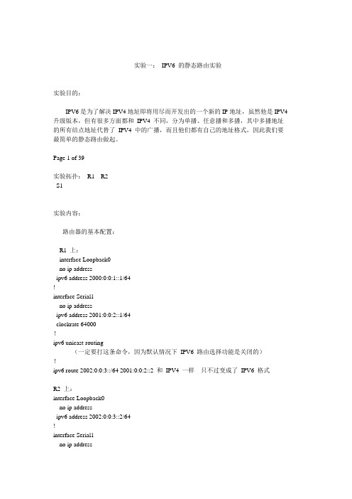
实验一:IPV6 的静态路由实验实验目的:IPV6是为了解决IPV4地址即将用尽而开发出的一个新的IP地址,虽然他是IPV4 升级版本,但有很多方面都和IPV4 不同,分为单播、任意播和多播,其中多播地址的所有结点地址代替了IPV4 中的广播,而且他们都有自己的地址格式,因此我们要最简单的静态路由做起。
Page 1 of 39实验拓扑:R1 R2S1实验内容:路由器的基本配置:R1 上:interface Loopback0no ip addressipv6 address 2000:0:0:1::1/64!interface Serial1no ip addressipv6 address 2001:0:0:2::1/64clockrate 64000!ipv6 unicast-routing(一定要打这条命令,因为默认情况下IPV6 路由选择功能是关闭的)!ipv6 route 2002:0:0:3::/64 2001:0:0:2::2 和IPV4 一样只不过变成了IPV6 格式R2 上:interface Loopback0no ip addressipv6 address 2002:0:0:3::2/64!interface Serial1no ip addressPage 2 of 39ipv6 address 2001:0:0:2::2/64!ipv6 unicast-routing!ipv6 route ::/0 2001:0:0:2::1 (这里用::/0 表示默认静态路由)R1 上的路由表:用sh ipv6 route 打开rack01#sh ipv routeIPv6 Routing Table - 9 entriesCodes: C - Connected, L - Local, S - Static, R - RIP, B - BGPU - Per-user Static routeI1 - ISIS L1, I2 - ISIS L2, IA - ISIS interarea, IS - ISIS summaryO - OSPF intra, OI - OSPF inter, OE1 - OSPF ext 1, OE2 - OSPF ext 2ON1 - OSPF NSSA ext 1, ON2 - OSPF NSSA ext 2C 2000:0:0:1::/64 [0/0]via ::, Loopback0L 2000:0:0:1::1/128 [0/0]via ::, Loopback0C 2001:0:0:2::/64 [0/0]via ::, Serial1L 2001:0:0:2::1/128 [0/0]via ::, Serial1S 2002:0:0:3::/64 [1/0]via 2001:0:0:2::2L FE80::/10 [0/0]via ::, Null0L FF00::/8 [0/0]via ::, Null0我们可以看到有一条S 的路由,是我们写的,他的管理距离是1,下一条是R2的S1 口。
计算机网络实验指导书CISCO版

计算机网络实验指导书 CISCO版实验一网络设备与通信协议实验1实验二 EIA568标准与双绞线水晶头制作13实验三交换机基本配置20实验四交换机VLAN配置25实验五路由器基本配置31实验六配置静态路由36实验七动态路由RIP配置42实验八动态路由OSPF协议配置50实验九访问控制列表ACL实验60实验十网络地址转换NAT实验65实验一网络设备与通信协议实验一、实验容学习使用网络基本设备,掌握设备性能和配置方法,熟悉LINUX和WINDOWS环境的TCP/IP协议配置方法,熟悉Internet环境,学习使用DOS下的常用网络命令。
二、实验目的了解网络适配器、调制解调器、集线器、交换机、路由器等网络硬件设备,熟悉多种网络操作系统,如LINUX和WINDOWS,掌握TCP/IP协议在不同操作系统下的安装与配置,初步掌握TCP/IP协议的应用。
掌握WINDOWS 环境常用网络命令的用法,学会使用网络命令查看网络信息,解决网络故障。
三、实验工具Quidway R2621模块化路由器、QuidwayS3026E交换机、Console配置线缆、双绞线、V24串口线缆、调制解调器、网络检测设备、PC等。
四、实验要求熟悉TCP/IP协议标准,准确理解IP地址与其子网划分方法,理解网关和子网掩码与其DNS的概念和原理;学习使用各种网络设备,掌握TCP/IP配置方法,熟练使用常用的网络命令。
五、实验容(1)在计算机上配置IP地址等TCP/IP属性信息(2)学习使用windows环境下常用的网络命令1.IP地址与以太网卡硬件地址查看命令:ipconfig2.网络连接测试命令:ping3.地址解析命令:ARP4.文件传输命令:FTP5.显示协议与其端口信息和当前的 TCP/IP 网络连接:Netstat6.控制网络路由表:Route7.将文件传输到正在运行TFTP 服务的远程计算机或从正在运行 TFTP服务的远程计算机传输文件:Tftp8.Tracert:该诊断实用程序将包含不同生存时间 (TTL) 值的 Internet 控制消息协议 (ICMP) 回显数据包发送到目标,以决定到达目标采用的路由。
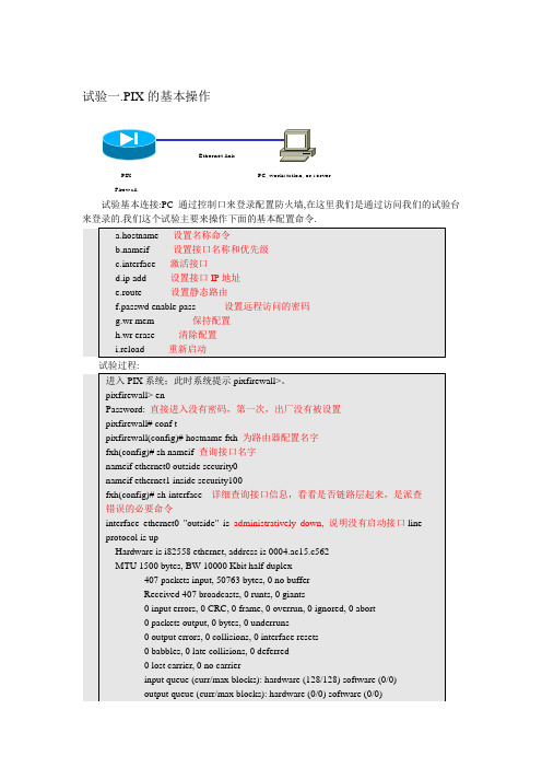
cisco安全试验手册

0 babbles, 0 late collisions, 0 deferred
0 lost carrier, 0 no carrier
input queue (curr/max blocks): hardware (128/128) software (0/1)
inside1.2.3.0 255.255.255.0 1.2.3.125 1 CONNECT static
0 packets output, 0 bytes, 0 underruns
0 output errors, 0 collisions, 0 interface resets
0 babbles, 0 late collisions, 0 deferred
0 lost carrier, 0 no carrier
pixfirewall(config)# hostname fxh为路由器配置名字
fxh(config)# sh nameif查询接口名字
nameif ethernet0 outside security0
nameif ethernet1 inside security100
fxh(config)# sh interface详细查询接口信息,看看是否链路层起来,是派查错误的必要命令
0 packets output, 0 bytes, 0 underruns
0 output errors, 0 collisions, 0 interface resets
0 babbles, 0 late collisions, 0 deferred
0 lost carrier, 0 no carrier
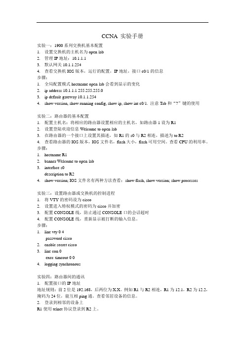
CCNA 实验手册

CCNA 实验手册实验一:1900系列交换机基本配置1.设置交换机的主机名为open-lab2.管理IP地址:10.1.1.13.默认网关10.1.1.2544.查看交换机IOS版本,运行的配置,IP地址,接口e0/1的信息步骤:1.全局配置模式hostname open-lab会看到显示的变化2.ip address 10.1.1.1 255.255.255.03.ip default-gateway 10.1.1.2544.show version, show running-config, show ip, show int e0/1. 注意Tab和“?”键的使用实验二:路由器的基本配置1.配置主机名:将相应的路由器设置相应的主机名,如路由器1设为R12.设置登陆欢迎信息Welcome to open-lab3.在路由器的一个接口上设置其描述,如R1的s0与R2相连,描述为to R24.查看路由器的IOS版本,IOS文件名,flash大小,flash可用空间。
查看CPU的利用率。
步骤:1.hostname R12.banner Welcome to open-lab3.interface s0description to R24.show version; IOS文件名有两种方法查看:show flash, show version; show processes实验三:设置路由器或交换机的控制进程1.将VTY的密码设为cisco2.设置进入特权模式的密码为cisco并加密3.配置CONSOLE线,防止通过CONSOLE口的会话超时4.配置CONSOLE线,重新显示被打断的输入信息。
步骤:1.line vty 0 4password cisco2.enable secret cisco3.line con 0exec-timeout 0 04.logging synchronous实验四:路由器间的通讯1.配置接口的IP地址地址规则:前2位是192.168,后两位为X.X。
Cisco CCIE ASA实验手册

cisco思科交换机试验手册之-实验16公用端口实验

实验十六、公用端口实验一、实验目的1.了解公用端口原理;2.熟练掌握交换机公用端口配置和使用场合;二、应用环境在实际应用中,我们发现,很多园区网的建设都需要有一个公共的端口存在,此端口与整个园区的公共服务器连接,这个服务器一般向内网所有用户开放,即同时向例如行政网络、学生网络、教员网络开放,但我们如果划分了VLAN,各个网络之间又不能互相通信了,又怎么解决这个问题呢?我们回顾 PVID和 VID的概念时发现,当一个端口接收到一个数据帧之后,会根据端口的PVID值在对应的等值VID端口中转发此数据帧,利用这一点,实现公用端口功能。
前提:交换机支持公用端口技术。
三、实验设备1、DCS-3726S交换机1台2、PC机3台3、Console线1根4、直通网线3根四、实验拓扑五、实验要求在交换机上划分V LAN:vlan100,vlan200,vlan300。
PC 端口VID PVIDPc1 1 100,300 100Pc2 2 200,300 200Pc3 24 100,200,300300PC1、PC2、PC3的网络设置为:设备IP地址MaskPC1 192.168.1.101 255.255.255.0PC2 192.168.1.102 255.255.255.0PC3 192.168.1.103 255.255.255.0把PC1、PC2、PC3接在相应的端口上进行验证:PC1和PC3,PC2和PC3之间可以正常通信,PC1和 PC2不可以直接通信。
若实验结果和理论相符,则本实验完成。
aaaaaaaaaaaaaaaaaaa.实验步骤第一步:交换机全部恢复出厂设置,进入vlan模式,创建三个vlanConsole(config)#vlan database !进入VLAN配置命令Console(config-vlan)#vlan 100 media ethernet state active !建立VLAN 100Console(config-vlan)#vlan 200 media ethernet state active !建立VLAN 200Console(config-vlan)#vlan 300 media ethernet state active !建立VLAN 300 第二步:进入interface模式,分配不同的vlanConsole(config-if)#interface ethernet 1/1Console(config-if)#switchport allowed vlan add 100,300 !配置VLAN的VIDConsole(config-if)#switchport native vlan 100 !配置VLAN的PVIDConsole(config-if)#interface ethernet 1/2Console(config-if)#switchport allowed vlan add 200,300 !配置VLAN的VIDConsole(config-if)#switchport native vlan 200 !配置VLAN的PVIDConsole(config)#interface ethernet 1/24Console(config-if)#switchport allowed vlan add 100,200,300!配置VLAN的VIDConsole(config-if)#switchport native vlan 300 !配置VLAN的PVIDConsole#copy running-config startup-config !配置文件存盘?Startup configuration file name []: pubport?Write to FLASH Programming.?Write to FLASH finish.?Success.第三步:Ping命令验证实验。
上海央邦Cisco实验手册(CCNA部分)

CCNA部分 (1)L AB 1路由器的基本配置 (1)L AB 2配置静态路由 (6)L AB 3配置动态路由协议 (8)L AB 4配置网络控制列表 (12)L AB 5配置帧中继 (16)L AB 6配置网络地址转换 (18)CCNP路由部分(BSCI) (22)L AB 1静态路由和RIP的巩固和加深 (22)L AB 2配置EIGRP及其高级特性 (28)L AB 3配置OSPF基本特性 (36)L AB 4OSPF在不同网络类型上的操作实验拓扑 (41)L AB 5配置集成IS-IS (44)L AB 6操纵路由选择更新 (46)L AB 7配置DHCP (50)L AB 8配置组播 (52)L AB 9配置IP V6路由 (55)L AB 10配置BGP (58)CCNP 多层交换部分(BCMSN) (66)L AB 1实施和配置VLAN (66)L AB 2 VLAN间路由 (70)L AB 3配置和实施STP (74)L AB 4配置C ATALYST交换机的Q O S (83)L AB 5配置多层交换机的HSRP (87)L AB 6配置HSRP的高级特性 (91)L AB 7配置交换机安全 (96)CCNP 安全部分(ISCW) (99)L AB 1配置MPLS VPN (99)L AB 2配置C ISCO IOS的站点到站点IPS EC VPN (106)L AB 3加强路由器远程管理的安全性 (112)L AB 4使用SDM配置EASY VPN (114)L AB 5使用CLI配置IOS防火墙 (125)CCNP优化部分(ONT) (131)L AB 1IP服务质量(Q O S)案例分析和实施 (131)CCIE PRE-LAB部分 (148)LAB1CCIE R&S模拟实验 (148)LAB2CCIE S ERVICE P ROVIDER 模拟实验 (161)央邦IT培训实验手册CCNA部分Lab 1 路由器的基本配置实验要求1.掌握路由器的用户模式、特权模式、配置模式的切换。
- 1、下载文档前请自行甄别文档内容的完整性,平台不提供额外的编辑、内容补充、找答案等附加服务。
- 2、"仅部分预览"的文档,不可在线预览部分如存在完整性等问题,可反馈申请退款(可完整预览的文档不适用该条件!)。
- 3、如文档侵犯您的权益,请联系客服反馈,我们会尽快为您处理(人工客服工作时间:9:00-18:30)。
CCNP BSCI Lab 1实验拓扑实验要求1.配置浮动静态路由,实现负载均衡和冗余,具体要求如下:a)R1转发到101.1.0.0/24网段和101.1.2.0/24的数据包时首选出口是E0/0.2,次选出口是E0/0.3b)R1转发到101.1.1.0/24网段和101.1.3.0/24的数据包时首选出口是E0/0.3,次选出口是E0/0.2c)R2转发到100.1.0.0/24网段和100.1.2.0/24的数据包时首选出口是E0/0.2,次选出口是E0/0.3d)R2转发到100.1.1.0/24网段和100.1.3.0/24的数据包时首选出口是E0/0.3,次选出口是E0/0.22.去掉要求1的静态路由配置,配置RIPv1,查看两台路由器的路由表,总结RIPv1的特点3.配置RIPv2,实现两台路由器能学到对方的所有子网4.将两台路由器的E0/0.2口配置为被动端口,这个接口只接收而不发送路由协议。
5.配置Offset-list,是两台路由器的loopback口在对方的路由表中变成5跳6.配置RIPv2的md5验证,实现两台路由器之间安全地传递路由信息7.配置RIPv2的汇总,在保证网络能正常通信的情况下尽量减小路由器的路由表实验步骤以下演示中的X以“0”为例,您在实验的X要使用自己的组号1. 配置置浮动静态路由,实现R1转发到101.1.0.0/24网段的数据包时首选出口是E0/0.2,次选出口是E0/0.3;R2转发到100.1.0.0/24网段的数据包时首选出口是E0/0.2,次选出口是E0/0.3;R1(config)#interface ethernet 0/0R1(config-if)#no shutdownR1(config-if)#exitR1(config)#interface ethernet 0/0.2R1(config-subif)#encapsulation dot1Q 2R1(config-subif)#ip address 1.1.0.1 255.255.255.0R1(config-subif)#exitR1(config)#interface ethernet 0/0.3R1(config-subif)#encapsulation dot1Q 3R1(config-subif)#ip address 1.2.0.1 255.255.255.0R1(config-subif)#exitR1(config)#interface loopback 0R1(config-if)#ip address 100.1.0.1 255.255.255.0R1(config-if)#exitR1(config)#interface loopback 1R1(config-if)#ip address 100.1.1.1 255.255.255.0R1(config-if)#exitR1(config)#interface loopback 2R1(config-if)#ip address 100.1.2.1 255.255.255.0R1(config-if)#exitR1(config)#interface loopback 3R1(config-if)#ip address 100.1.3.1 255.255.255.0R1(config-if)#exitR2(config)#interface ethernet 0/0R2(config-if)#no shutdownR2(config-if)#exitR2(config)#interface ethernet 0/0.2R2(config-subif)#encapsulation dot1Q 2R2(config-subif)#ip address 1.1.0.2 255.255.255.0R2(config-subif)#exitR2(config)#interface ethernet 0/0.3R2(config-subif)#encapsulation dot1Q 3R2(config-subif)#ip address 1.2.0.2 255.255.255.0R2(config-subif)#exitR2(config)#interface loopback 0R2(config-if)#ip address 101.1.0.1 255.255.255.0R2(config-if)#exitR2(config)#interface loopback 1R2(config-if)#ip address 101.1.1.1 255.255.255.0R2(config-if)#exitR2(config)#interface loopback 2R2(config-if)#ip address 101.1.2.1 255.255.255.0R2(config-if)#exitR2(config)#interface loopback 3R2(config-if)#ip address 101.1.3.1 255.255.255.0R2(config-if)#exitR2(config)#检查R1和R2的接口状态R1#show protocolsGlobal values:Internet Protocol routing is enabledEthernet0/0 is up, line protocol is upEthernet0/0.2 is up, line protocol is upInternet address is 1.1.0.1/24Ethernet0/0.3 is up, line protocol is upInternet address is 1.2.0.1/24Ethernet0/1 is administratively down, line protocol is down Loopback0 is up, line protocol is upInternet address is 100.1.0.1/24Loopback1 is up, line protocol is upInternet address is 100.1.1.1/24Loopback2 is up, line protocol is upInternet address is 100.1.2.1/24Loopback3 is up, line protocol is upInternet address is 100.1.3.1/24R2#show protocolsGlobal values:Internet Protocol routing is enabledEthernet0/0 is up, line protocol is upEthernet0/0.2 is up, line protocol is upInternet address is 1.1.0.2/24Ethernet0/0.3 is up, line protocol is upInternet address is 1.2.0.2/24Ethernet0/1 is administratively down, line protocol is down Loopback0 is up, line protocol is upInternet address is 101.1.0.1/24Loopback1 is up, line protocol is upInternet address is 101.1.1.1/24Loopback2 is up, line protocol is upInternet address is 101.1.2.1/24Loopback3 is up, line protocol is upInternet address is 101.1.3.1/24检查R1和R2的路由表R1#show ip route ------一共有6个条目Gateway of last resort is not set1.0.0.0/24 is subnetted, 2 subnetsC 1.1.0.0 is directly connected, Ethernet0/0.2C 1.2.0.0 is directly connected, Ethernet0/0.3100.0.0.0/24 is subnetted, 4 subnetsC 100.1.1.0 is directly connected, Loopback1C 100.1.0.0 is directly connected, Loopback0 C 100.1.3.0 is directly connected, Loopback3 C 100.1.2.0 is directly connected, Loopback2R2#show ip routeGateway of last resort is not set1.0.0.0/24 is subnetted, 2 subnetsC 1.1.0.0 is directly connected, Ethernet0/0.2 C 1.2.0.0 is directly connected, Ethernet0/0.3 101.0.0.0/24 is subnetted, 4 subnetsC 101.1.0.0 is directly connected, Loopback0 C 101.1.1.0 is directly connected, Loopback1 C 101.1.2.0 is directly connected, Loopback2 C 101.1.3.0 is directly connected, Loopback3配置浮动静态路由:R1(config)#ip route 101.1.0.0 255.255.255.0 1.1.0.2 R1(config)#ip route 101.1.0.0 255.255.255.0 1.2.0.2 5 R1(config)#ip route 101.1.2.0 255.255.255.0 1.1.0.2 R1(config)#ip route 101.1.2.0 255.255.255.0 1.2.0.2 5 R1(config)#ip route 101.1.1.0 255.255.255.0 1.2.0.2 R1(config)#ip route 101.1.1.0 255.255.255.0 1.1.0.2 5 R1(config)#ip route 101.1.3.0 255.255.255.0 1.2.0.2 R1(config)#ip route 101.1.3.0 255.255.255.0 1.1.0.2 5R2(config)#ip route 100.1.0.0 255.255.255.0 1.1.0.1 R2(config)#ip route 100.1.0.0 255.255.255.0 1.2.0.1 5 R2(config)#ip route 100.1.2.0 255.255.255.0 1.1.0.1 R2(config)#ip route 100.1.2.0 255.255.255.0 1.2.0.1 5 R2(config)#ip route 100.1.1.0 255.255.255.0 1.2.0.1 R2(config)#ip route 100.1.1.0 255.255.255.0 1.1.0.1 5 R2(config)#ip route 100.1.3.0 255.255.255.0 1.2.0.1 R2(config)#ip route 100.1.3.0 255.255.255.0 1.1.0.1 5检查(以R1为例)R1#show ip routeGateway of last resort is not set1.0.0.0/24 is subnetted, 2 subnetsC 1.1.0.0 is directly connected, Ethernet0/0.2 C 1.2.0.0 is directly connected, Ethernet0/0.3 100.0.0.0/24 is subnetted, 4 subnetsC 100.1.1.0 is directly connected, Loopback1 C 100.1.0.0 is directly connected, Loopback0 C 100.1.3.0 is directly connected, Loopback3 C 100.1.2.0 is directly connected, Loopback2 101.0.0.0/24 is subnetted, 4 subnetsS 101.1.0.0 [1/0] via 1.1.0.2S 101.1.1.0 [1/0] via 1.2.0.2S 101.1.2.0 [1/0] via 1.1.0.2S 101.1.3.0 [1/0] via 1.2.0.2R1(config)#interface ethernet 0/0.2R1(config-subif)#shutdownR1#show ip route1.0.0.0/24 is subnetted, 1 subnetsC 1.2.0.0 is directly connected, Ethernet0/0.3 100.0.0.0/24 is subnetted, 4 subnetsC 100.1.1.0 is directly connected, Loopback1 C 100.1.0.0 is directly connected, Loopback0 C 100.1.3.0 is directly connected, Loopback3 C 100.1.2.0 is directly connected, Loopback2 101.0.0.0/24 is subnetted, 4 subnetsS 101.1.0.0 [5/0] via 1.2.0.2S 101.1.1.0 [1/0] via 1.2.0.2S 101.1.2.0 [5/0] via 1.2.0.2S 101.1.3.0 [1/0] via 1.2.0.2测试完要把被关闭的接口打开,以免影响后面的实验2.去掉要求1的静态路由配置,配置RIPv1,查看两台路由器的路由表,总结RIPv1的特点R1(config)#no ip routingR1(config)#ip routingR1(config)#router ripR1(config-router)#network 1.0.0.0R1(config-router)#network 100.0.0.0R2(config)#no ip routingR2(config)#ip routingR2(config)#router ripR2(config-router)#network 1.0.0.0R2(config-router)#network 101.0.0.0R1#show ip protocolsRouting Protocol is "rip"Sending updates every 30 seconds, next due in 26 secondsInvalid after 180 seconds, hold down 180, flushed after 240Outgoing update filter list for all interfaces is not setIncoming update filter list for all interfaces is not setRedistributing: ripDefault version control: send version 1, receive any versionInterface Send Recv Triggered RIP Key-chainEthernet0/0.2 1 1 2 Ethernet0/0.3 1 1 2 Loopback0 1 1 2 Loopback1 1 1 2 Loopback2 1 1 2 Loopback3 1 1 2 Automatic network summarization is in effectMaximum path: 4Routing for Networks:1.0.0.0100.0.0.0Routing Information Sources:Gateway Distance Last Update1.2.0.2 120 00:00:071.1.0.2 120 00:00:07Distance: (default is 120)R1# show ip route1.0.0.0/24 is subnetted, 2 subnetsC 1.1.0.0 is directly connected, Ethernet0/0.2C 1.2.0.0 is directly connected, Ethernet0/0.3100.0.0.0/24 is subnetted, 4 subnetsC 100.1.1.0 is directly connected, Loopback1C 100.1.0.0 is directly connected, Loopback0C 100.1.3.0 is directly connected, Loopback3C 100.1.2.0 is directly connected, Loopback2R 101.0.0.0/8 [120/1] via 1.1.0.2, 00:00:23, Ethernet0/0.2 [120/1] via 1.2.0.2, 00:00:20, Ethernet0/0.3通过查看RIPv1的工作状态和路由表回答以下问题:a.RIP每________秒发送一次更新b.默认情况下,RIP发送版本_____,接收版本_____.c.RIP默认管理距离是_______d.RIP最大支持_____条等价路径e.RIPv1是_____类路由协议(有/无)3.配置RIPv2,实现两台路由器能学到对方的所有子网R1(config)#router ripR1(config-router)#version 2R1(config-router)#no auto-summaryR2(config)#router ripR2(config-router)#version 2R2(config-router)#no auto-summaryR1#clear ip rout *R1#shR1#show ip routR1#show ip routeGateway of last resort is not set1.0.0.0/24 is subnetted, 2 subnetsC 1.1.0.0 is directly connected, Ethernet0/0.2C 1.2.0.0 is directly connected, Ethernet0/0.3100.0.0.0/24 is subnetted, 4 subnetsC 100.1.1.0 is directly connected, Loopback1C 100.1.0.0 is directly connected, Loopback0C 100.1.3.0 is directly connected, Loopback3C 100.1.2.0 is directly connected, Loopback2101.0.0.0/24 is subnetted, 4 subnetsR 101.1.0.0 [120/1] via 1.1.0.2, 00:00:01, Ethernet0/0.2 [120/1] via 1.2.0.2, 00:00:02, Ethernet0/0.3 R 101.1.1.0 [120/1] via 1.1.0.2, 00:00:02, Ethernet0/0.2 [120/1] via 1.2.0.2, 00:00:02, Ethernet0/0.3 R 101.1.2.0 [120/1] via 1.1.0.2, 00:00:03, Ethernet0/0.2 [120/1] via 1.2.0.2, 00:00:03, Ethernet0/0.3 R 101.1.3.0 [120/1] via 1.1.0.2, 00:00:03, Ethernet0/0.2 [120/1] via 1.2.0.2, 00:00:03, Ethernet0/0.34. 将两台路由器的E0/0.2口配置为被动端口R1(config)#router ripR1(config-router)#passive-interface ethernet 0/0.2R2(config)#router ripR2(config-router)#passive-interface ethernet 0/0.2由于R2将E0/0.2口配置成了被动端口,故R1无法通过1.1.0.2获得RIP路由了。
