Dynamic buckling and fragmentation in brittle rods
Quantum spin liquid emerging in 2D correlated Dirac fermions

焊接词典

焊接词典乙炔 acetylene电流安培 ampere角焊 angle welding电弧 arc氩弧焊接 argon arc welding光熔接条 bare electrode对接焊接 butt welding电弧弯曲 camber阶叠熔接法 cascade被覆熔接 clad weld熔接 fusion welding压接 pressure welding焊接过程 welding process焊接技术 welding technique焊接工艺 welding technology/procedure焊接操作 welding operation焊接顺序 welding sequence焊接方向 direction of welding焊接位置 welding position熔敷顺序 build-up sequence/deposition sequence焊缝倾角 weld slope/inclination of weld axis焊缝转角 weld rotation/angle of rotation平焊位置flat position of welding横焊位置horizontal position of welding立焊位置vertical position of welding仰焊位置overhead position of welding平焊downhand welding/flat position welding横焊horizontal position welding立焊vertical position welding仰焊overhead position welding全位置焊all position welding:熔焊时,焊件接逢所处空间位置包括平焊、横焊、仰焊等位置所进行的焊接。
如水平固定管所进行的环缝焊接向下立焊vertical down welding/downward welding in the vertical position向上立焊vertical up welding/upward welding in the vertical position倾斜焊inclined position welding上坡焊upward welding in the inclined position下坡焊downward welding in the inclined position对接焊butt welding角焊fillet welding搭接焊lap welding船形焊fillet welding in the downhand position/fillet welding in the flat position平角焊horizontal fillet welding立角焊fillet welding in the vertical position仰角焊fillet welding in the overhead position坡口焊groove weldingI形坡口对接焊square butt welding喇叭形坡口焊flare groove welding卷边焊flanged edge welding纵缝焊接welding of longitudinal seam横缝焊接welding of transverse seam环缝焊接girth welding/ circumferential螺旋缝焊接welding of spiral seam/welding of helical seam 环缝对接焊butt welding of circumferential seam定位焊tack welding单面焊welding by one side双面焊welding by both sides单道焊single pass welding/single run welding多道焊multi-pass welding单层焊single layer welding多层焊multi-layer welding分段多层焊block sequence/ block welding分层多道焊multi-layer and multi-pass welding连续焊continuous welding断续焊intermittent welding打底焊backing weld封底焊back sealing weld盖面焊cosmetic welding深熔焊deep penetration welding摆动焊welding with weaving/weave bead welding前倾焊foreward welding (英国)/ forehand welding (美国)后倾焊backward welding(英国)/ backhand welding(美国) 分段退焊backstep welding跳焊skip welding对称焊balanced welding/ balanced welding sequence左焊法leftward welding forehand welding右焊法rightward welding/backhand welding挑弧焊whipping method自动焊automatic welding手工焊manual welding/hand welding车间焊接shop welding工地焊接site welding(英国)/ field welding (美国)拘束焊接restraint welding堆焊surfacing/building up/overlaying隔离层堆焊buttering端部周边焊boxing/end return返修焊rewelding补焊repair welding塞焊plug welding槽焊slot welding衬垫焊welding with backing焊剂垫焊welding with flux backing窄间隙焊narrow-gap welding强制成形焊enclosed welding脉冲电弧焊pulsed are welding电弧点焊arc spot welding螺柱焊stud welding热风焊hot gas welding高能焊high grade energy welding固态焊接solid-state welding单面焊双面成形one-side welding with back formation 焊接条件welding condition焊接工艺参数welding parameter极性polarity正接electrode negative/straight polarity反接electrode positive/reversed polarity运条方式manipulation of electrode焊接电流welding current焊接电流增加时间welding current upslope time焊接电流衰减时间welding current downslope time电流密度current density短路电流short circuit current脉冲电流pulse level/pulse current level脉冲电流幅值pulse current amplitude基值电流background level脉冲频率pulse frequency脉冲焊接电流占空比duty cycle of pulse duration电弧电压arc voltage再引弧电压reignition voltage焊接速度welding speed行走速度rate of travel/travel speed送丝速度wire feed rate线能量heat input/energy input热输入heat input预热preheat后热postheat焊后热处理posweld heat treatment/postheat treatment 预热温度preheat temperature层间温度interpass temperature焊接终了温度finishing temperature后热温度postheating temperature焊丝伸出长度wire extension弧长arc length熔化速度melting rate熔化时间melting time熔化系数melting coefficient熔敷速度rate of deposition/deposition rate熔敷系数deposition coefficient熔敷效率deposition efficiency损失系数loss coefficient飞溅spatter飞溅率spatter loss coefficient融合比fusion ratio稀释dilution稀释率rate of dilution合金过度系数transfer efficiency/recovery (of an element) 坡口groove坡口面groove face坡口面角度angle of bevel (英国)/ bevel angle (美国)坡口角度included angle(英国)/groove angle(美国)坡口高度groove depth钝边root face钝边高度thickness of root face/width of root face根部间隙root gap(英国)/root opening (美国)根部半径root radius/groove radius根部锐边root edge卷边高度height of flange卷边半径radius of flange单面坡口single groove双面坡口double groove坡口形式groove typeI形坡口square grooveV形坡口single V grooveY形坡口single V groove with root face双Y形坡口double Vgroove with root face带钝边U形坡口single U groove带钝边双U形坡口double U grooveVY形坡口single compound angle groove带钝边J形坡口single J groove带钝边双J形坡口double J groove单边V形坡口single bevel groove双V形坡口double V groove不对称双V形坡口asymmetric double V groove双单边V形坡口double bevel groove/K groove带垫板V形坡口V groove with backing/ single V groove with backing 喇叭形坡口flare groove锁底坡口single bevel groove with backing locked坡形板边tapered edge焊缝weld接逢seam焊缝符号welding symbol焊缝金属weld metal填充金属filler metal熔敷金属deposited metal焊缝表面weld face/ face of weld焊缝背面back of weld焊缝轴线axis of weld焊缝尺寸size of weld焊缝宽度weld width/ width of weld焊缝长度weld length/ length of weld焊缝有效长度effective length of weld焊缝厚度throat depth/ throat thickness焊缝计算厚度theoretical throat焊缝实际厚度actual throat熔深penetration/ depth of penetration焊缝成形appearance of weld焊缝成形系数form factor of weld余高reinforcement/ excess weld metal背面余高root reinforcement削平焊缝flush weld/ weld machined flush对接焊缝butt weld角焊缝fillet焊脚leg/ fillet weld leg角焊缝断面形状profile of fillet weld平形角焊缝flat fillet凸形角焊缝convex fillet weld凹形角焊缝concave fillet weld角焊缝凹度concavity侧面角焊缝side fillet weld/ fillet weld in parallel shear 正面角焊缝front fillet weld/ fillet weld in normal shear 立角焊缝fillet weld in the vertical position横角焊缝fillet weld in the horizontal position平角焊缝fillet weld in the flat position斜角焊缝oblique fillet weld连续焊缝continuous weld断续焊缝intermittent weld连续角焊缝continuous fillet weld断续角焊缝intermittent fillet weld交错断续角焊缝staggered intermittent fillet weld并列断续角焊缝chain intermittent fillet weld端接焊缝edge weld卷边焊缝flanged edge weld塞焊焊缝plug weld纵向焊缝longitudinal weld横向焊缝transverse weld环行焊缝girth weld/ circumferential weld螺旋形焊缝spiral weld/ helical weld密封焊缝seal weld承载焊缝strength weld联系焊缝connective weld定位焊缝tack weld焊道bead/ run/ pass焊波ripple焊根weld root/ root of weld焊趾weld toe/ toe封底焊道sealing run (after making main weld)/ back weld打底焊道backing weld (before making main weld)/ back weld 根部焊道root pass/ root run填充焊道filling bead盖面焊道cosmetic bead/ cover pass回火焊道temper bead/ annealing bead熔透焊道penetration bead焊层layer焊接接头 welded joint接头形状 joint geometry等强匹配接头equalmatching weld joint低强匹配接头undermatching weld joint超强匹配接头overmatching weld joint接头根部root of joint对接接头butt jointI形对接接头square butt jointV形对接接头single V butt jointU形对接接头single U butt jointJ形坡口接头single J butt joint双V形对接接头double V butt joint双单边V形对接接头double bevel butt joint/ K groove butt joint 带钝边U形对接接头double U butt joint带钝边J形坡口接头double J joint角接接头corner jointT形接头T joint斜T形接头inclined T joint十字接头cruciform joint/ cross-shaped joint三联接头joint among three members搭接接头lap joint套管接头muff joint/ sleeve joint双盖板接头double strapped joint盖板接头strapped joint端接接头edge joint卷边接头flanged edge joint锁底对接接头lock butt joint斜对接接头oblique butt joint混合接头mixed joint/ composite joint有间隙接头open joint无间隙接头closed joint焊接电弧welding arc电弧形态arc shape电弧物理行为arc physics behaviour引弧striking arc引弧电压striking voltage电弧气氛arc atmosphere阴极cathode热阴极hot cathode冷阴极cold cathode阴极斑点cathode spot阴极区cathode region阴极区电场强度intensity of the electric field in the cathode region 阴极压降cathode drop阳极anode阳极斑点anode spot斑点压力spot pressure阳极区anode region阳极区电场强度intensity of the electric field in the anode region 阳极压降anode drop弧柱arc column/ arc stream弧柱压降voltage drop in arc column弧柱电位梯度potential gradient in the arc column弧焰arc flame弧心arc core(焊接网 )硬电弧forceful arc/ hard arc软电弧soft arc旋转电弧rotating arc脉冲电弧pulsed arc脉冲喷射电弧pulsed spray arc起皱现象puckering phenomena起皱电弧puckering arc起皱临界电流puckering critical current间接电弧indirect arc压缩电弧compressive arc磁控电弧magnetic controlling arc电弧力arc force电磁力electromagnectic force电磁收缩效应pinch effect电弧飘移wandering of arc电弧稳定性arc stability电弧静特性static characteristic of arc电弧动特性dynamic characteristic of arc最小电压原理principle of minimum voltage 电弧挺度arc stiffness电弧偏吹arc blow磁偏吹magnetic blow阴极清理作用cleaning action of the cathode 电弧自身调节arc self-regulation挖掘作用digging action极性效应polarity effect熔滴droplet熔滴比表面积specific surface of droplet熔滴过渡metal transfer过度频率transition frequency粗滴过渡globular transfer; drop transfer短路过渡short circuiting transfer喷射过渡spray transfer旋转喷射过渡rotating spray transfer脉冲喷射过渡pulsed spray transfer爆炸过渡explosive transfer渣壁过渡flux wall guided transfer熔池molten pool沸腾状熔池boiling molten pool弧坑crater熔渣slag渣系slag system渣系相图slag system diagram碱性渣basic slag酸性渣acid slag碱度basicity酸度acidity长渣long slag短渣short slag粘性熔渣viscous slag氧化物型熔渣oxide melting slag盐型熔渣salt melting slag盐-氧化物型熔渣salt-oxide melting slag熔渣流动性fluidity of the slag; slag fluidity 熔渣solidified slag多孔焊渣porous slag玻璃状焊渣vitreous slag自动脱落焊渣self-releasing slag脱渣性slag detachability焊接设备welding equipment; welding set焊机welding machine; welder电焊机electric welding machine; electric welder焊接电源welding power source焊接热循环weld thermal cycle焊接温度场field of weld temperature; weld temperature field 准稳定温度场quasi-stationary temperature field焊接热源welding heat source点热源point heat source线热源linear heat source面热源plane heat source瞬时集中热源instantaneous concentration heat source热效率thermal efficiency热能集中系数coefficient of heat flow concentration峰值温度peak temperature瞬时冷却速度momentary cooling rate冷却时间cooling time置换氧化substitutionary oxydation扩散氧化diffusible oxydation脱氧desoxydation先期脱氧precedent desoxydation扩散脱氧diffusible desoxydation沉淀脱氧precipitation desoxydation扩散氢diffusible hydrogen初始扩散氢initial diffusible hydrogen100℃残余扩散氢diffusible hydrogen remained at 100℃残余氢residual hydrogen去氢dehydrogenation去氢热处理heat treatment for dehydrogenation脱硫desulphurization脱磷dephosphorization渗合金alloying微量合金化microalloying一次结晶组织primary solidification structure二次结晶组织secondary solidification structure联生结晶epitaxial solidification焊缝结晶形态solidification mode in weld-bead结晶层状线ripple多边化边界polygonization boundary结晶平均线速度mean solidification rate针状铁素体acicular ferrite条状铁素体lath ferrite侧板条铁素体ferrite side-plate晶界欣素体grain boundary ferrite; polygonal ferrite; pro-entectoid ferrite 粒状贝氏体granular bainite板条马氏体lath martensite过热组织overheated structure魏氏组织Widmannst?tten structureM-A组元martensite-austenite constituent焊件失效分析failure analysis of weldments冷裂判据criterion of cold cracking冷裂敏感系数cold cracking susceptibity coefficient 脆性温度区间brittle temperature range氢脆hydrogen embrittlement层状偏析lamellar segregation愈合healing effect断口金相fractography断口fracture延性断口ductile fracture韧窝断口dimple fracture脆性断口brittle fracture解理断口cleavage fracture准解理断口quasi-cleavage fracture氢致准解理断口hydrogen-embrittlement induced 沿晶断口intergranular fracture穿晶断口transgranular fracture疲劳断口fatigue fracture滑移面断口glide plane fracture断口形貌fracture apperance断口试验fracture test宏观断口分析macrofractography放射区radical zone纤维区fibrous zone剪切唇区shear lip aone焊接性weldability使用焊接性service weldability工艺焊接性fabrication weldability冶金焊接性metallurgical weldability热焊接性thermal weldability母材base metal; parent metal焊接区weld zone焊态as-welded (AW)母材熔化区fusion zone半熔化区partial melting region未混合区unmixed zone熔合区bond area熔合线weld junction (英);bond line (美) 热影响区heat-affected zone (HAZ)过热区overheated zone粗晶区coarse grained region细晶区fine grained region过渡区transition zone硬化区hardened zone碳当量carbon equivalent铬当量chromium equivalent镍当量nickel equivalent舍夫勒组织图Schaeffler's diagram德龙组织图Delong’s diagram连续冷却转变图(CCT图)continuous cooling transformation 裂纹敏感性cracking sensibility焊接裂纹weld crack焊缝裂纹weld metal crack焊道裂纹bead crack弧坑裂纹crater crack热影响区裂纹heat-affected zone crack纵向裂纹longitudinal crack横向裂纹transverse crack微裂纹micro-crack; micro-fissure热裂纹hot crack凝固裂纹solidification crack晶间裂纹intercrystalline crack穿晶裂纹transcrystalline crack多边化裂纹polygonization crack液化裂纹liquation crack失延裂纹ductility-dip crack冷裂纹cold crack延迟裂纹delayed crack氢致裂纹hydrogen-induced crack焊道下裂纹underbead crack焊根裂纹root crack焊趾裂纹toe crack锯齿形裂纹chevron cracking消除应力处理裂纹stress relief annealing crack (SR crack)再热裂纹reheat crack焊缝晶间腐蚀weld intercryctalline corrosion刀状腐蚀knife line attack敏化区腐蚀weld decay层状撕裂lamellar tearing焊接性试验weldability裂纹试验cracking testIIW裂纹试验IIW cracking testY形坡口裂纹试验slit type cracking test分块形槽热裂纹试验segmented circular groove cracking testH形裂纹试验H-type cracking test鱼骨形裂纹试验fishbone cracking test指形裂纹试验finger (cracking) testT形裂纹试验Tee type cracking test环形槽裂纹试验circular-groove cracking test可调拘束裂纹试验varestraint testBWRA奥氏体钢裂纹试验BWRA cracking test for austenitie steel圆棒裂纹试验bar type cracking test; round bar cracking test里海裂纹试验Lehigh restraint cracking test圆形镶块裂纹试验circular-path cracking test十字接头裂纹试验cruciform cracking testZ向窗口拘束裂纹试验Z-direction window type restraint cracking testG-BOP焊缝金属裂纹试验G-BOP weld metal crack test巴特尔焊道下裂纹试验Battelle type underbead cracking testU形拉伸试验U-tension test缪雷克期热裂纹试验Murex hot cracking test菲斯柯裂纹试验FISCO (type) cracking testCTS裂纹试验controlled thermal severity拉伸拘束裂纹试验(TRC试验)tensile restraint cracking test 刚性拘束裂纹试验(RRC试验)rigid restraint cracking test (焊接网 )插销试验implant testTigamajig 薄板焊接裂纹试验Tigamajing thin plate cracking test 焊道纵向弯曲试验longitudinal-bead test柯麦雷尔弯曲试验Kommerell bead bend test肯泽尔弯曲试验Kinzel test缺口弯曲试验notch bend test热朔性试验hot-ductility test热影响区冲击试验impact test of HAZ热影响区模拟试验synthetic heat-affected zone test最高硬度试验maximum hardness test落锤试验NRL (Naval Research Laboratory)测氢试验Hydrogen test焊接材料welding consumables电极electrode熔化电极consumable electrode不熔化电极nonconsumable electrode钨电极tungsten electrode焊丝welding wire. Welding rod实心焊丝solid wire渡铜焊丝copper-plating welding wire自保护焊丝self-shielded welding wire药芯焊丝flux-cored wire复合焊丝combined wire堆焊焊丝surfacing welding rod填充焊丝filler wire焊条electrode/ covered electrode焊芯core wire药皮coating (of an electrode)/ covering (of an electrode) 涂料coating flux/coating material造气剂gas forming constituents造渣剂slag forming constituents合金剂alloying constituent脱氧剂dioxidizer稳弧剂arc stabilizer粘接剂binder水玻璃water glass水玻璃模数modules of water glass酸性焊条acid electrode高钛型焊条high titania (type) electrode钛钙型焊条lime titania type electrode钛铁矿形焊条ilmenite type electrode氧化铁型焊条iron oxide type electrode/ high iron oxide type electrode高纤维素型焊条high cellulose (type) electrode石墨型焊条graphite type electrode碱性焊条basic electrode/ lime type covered electrode低氢型焊条low hydrogen type electrode高韧性超低氢焊条high toughness super low hydrogen electrode奥氏体焊条austenitic electrode铁素体焊条ferritic electrode不锈钢焊条stainless steel electrode珠光体耐热钢焊条pearlitic heat resistant steel electrode低温钢焊条low temperature steel electrode/ steel electrode for low temperature 铝合金焊条aluminum alloy arc welding electrode铜合金焊条copper-alloy arc welding electrode铜芯铸铁焊条cast iron electrode with steel core纯镍铸铁焊条pure nickel cast iron electrode球墨铸铁焊条electrode for welding spheroidal graphite cast iron铸芯焊条electrode with cast core wire镍基合金焊条nickel base alloy covered electrode蒙乃尔焊条Monel electrode纯铁焊条pure iron electrode渗铝钢焊条alumetized steel electrode高效率焊条high efficiency electrode铁粉焊条iron powder electrode底层焊条backing welding electrode深熔焊条deep penetration electrode重力焊条gravity electrode立向下焊条electrode for vertical down position welding节能焊条saving energy electrode水下焊条underwater welding electrode耐海水腐蚀焊条seawater corrosion resistant steel electrode低尘低毒焊条low-fume and harmfulless electrode / low-fume and low-toxic electrode堆焊焊条surfacing electrode耐磨堆焊焊条hardfacing electrode钴基合金堆焊焊条cobalt base alloy surfacing electrode碳化钨堆焊焊条tungsten carbide surfacing electrode高锰钢堆焊焊条high manganese steel surfacing electrode双芯焊条twin electrode绞合焊条stranded electrode编织焊条braided electrode双层药皮焊条double coated electrode管状焊条flux-cored electrode气渣联合保护型药皮semi-volatile covering焊条工艺性usability of the electrode/ technicality of the electrode焊条使用性running characteristics of an electrode/ operating characteristics of an electrode 焊条熔化性melting characteristics of an electrode焊条直径core diameter焊条偏心度eccentricity (of an electrode)药皮重量系数gravity coefficient of coating焊条药皮含水量percentage of moisture for covering焊条夹吃持端bare terminal (of an electrode)焊条引弧端striking end (of an elcetrode)焊剂welding flux/ flux熔炼焊剂fused flux粘结焊剂bonded flux烧结焊剂sintered flux/ agglomerated flux窄间隙埋弧焊焊剂flux for narrow-gap submerged arc welding 低氢型焊剂low hydrogen type flux高速焊剂high speed welding flux无氧焊剂oxygen-free flux低毒焊剂low poison flux磁性焊剂magnetic flux电弧焊arc welding直流电弧焊direct current arc welding交流电弧焊alternating current arc welding三相电弧焊three phase arc welding熔化电弧焊arc welding with consumable金属极电弧焊metal arc welding不熔化极电弧焊arc welding with nonconsumable碳弧焊carbon arc welding明弧焊open arc welding焊条电弧焊shielded metal arc welding (SMAW)重力焊gravity welding躺焊fire cracker welding电弧堆焊arc surfacing自动堆焊automatic surfacing躺板极堆焊surfacing by fire cracker welding带极堆焊surfacing with band-electrode振动电弧堆焊vibratory arc surfacing耐磨堆焊hardfacing埋弧焊submerged arc welding (SAW)多丝埋弧焊multiple wire submerged arc welding纵列多丝埋弧焊Tandem sequence (submerged-arc welding) 横列多丝埋弧焊series submerged arc welding (SAW-S)横列双丝并联埋弧焊transverse submerged arc welding热丝埋弧焊hot wire submerged-arc welding窄间隙埋弧焊narrow-gap submerged arc welding弧压反馈电弧焊arc voltage feedback controlling arc welding 自调节电弧焊self-adjusting arc welding适应控制焊接adaptive control welding焊剂层burden; flux layer气体保护电弧焊gas shielded arc welding保护气体protective atmosphere惰性气体inert-gas活性气体active-gas惰性气体保护焊inert-gas (arc) welding氩弧焊argon arc welding熔化极惰性气体保护电弧焊metal inert-gas arc welding钨极惰性气体保护电弧焊tungsten inert-gas arc welding钨极氢弧焊argon tungsten arc welding脉冲氢弧焊pulsed argon arc welding熔化极脉冲氢弧焊argon metal pulsed arc welding钨极脉冲氢弧焊argon tungsten pulsed arc welding热丝MIG焊hot wire MIG welding热丝TIG焊hot wire TIG welding氨弧焊helium-arc welding活性气体保护电弧焊metal active-gas arc welding混合气体保护电弧焊mixed gas arc welding二氧化碳气体保护电弧焊carbon-dioxide arc welding; CO2 arc welding 细丝CO2焊CO2 arc welding with thin wire粗丝CO2焊CO2 arc welding with thick wire磁性焊剂CO2焊unionarc welding药芯焊丝CO2焊arcos arc process; dual shield arc welding气电立焊electrogas (arc) welding氮弧焊nitrogen-arc welding水蒸气保护电弧焊water vapour arc welding原子氢焊atomic hydrogen welding冲器室中电弧焊controlled atmosphere arc welding旋转电弧焊rotating arc welding短路过渡电弧焊short circuiting arc welding 焊丝横摆频率weaving speed of wire焊丝停摆时间electrode keep time of slider等离子弧焊plasma arc welding (PAW)等离子弧plasma arc等离子流plasma jet转移弧transferred arc非转移弧nontransferred arc联合型等离子弧combined plasma arc主弧main arc维弧pilot arc维弧电流pilot arc surrent双弧现象double arcing双弧临界电流critical current of double arcing 等离子弧焊枪plasma (welding) torch压缩喷嘴constricting nozzle单孔喷嘴single port nozzle多孔喷嘴multiport nozzle压缩喷嘴孔径orifice diameter孔道长度orifice throat length孔道比orifice throat ratio等离子气plasma gas; orifice gas电极内缩长度electrode setback小孔效应keyhole effect小孔型等离子弧焊keyhole-mode welding熔透型等离子弧焊fusion type plasma arc welding大电流等离子弧焊high-current plasma arc welding中电流等离子弧焊intermediate-current plasma arc welding 小电流等离子弧焊low-current plasma arc welding微束等离子弧焊micro-plasma arc welding交流等离子弧焊AC plasma arc welding脉冲等离子弧焊pulsed plasma arc welding等离子弧堆焊plasma arc surfacing热丝等离子弧堆焊hot wire plasma arc surfacing粉末等离子弧堆焊plasma arc powder surfacing等离子-熔化极惰性气体保护电弧焊plasma MIG welding 转移弧电源transferred arc power supply非转移弧电源nontransferred arc power supply电弧焊设备arc welding equipment电弧焊机arc welding machine直流弧焊机DC arc welding machine交流弧焊机AC arc welding machine交直流两用弧焊机AC/DC arc welding machine单站弧焊机single operator arc welding machine多站弧焊机multi-operator arc welding set固定式弧焊机stationary arc welding machine移动式弧焊机portable arc welding machine台式弧焊机bench arc welding machine内燃机驱动式弧焊机combustion engine driven arc welding set电动机驱动式弧焊机motor driven arc welding set熔化极弧焊机arc welding machine using a consumable electrode不熔化极弧焊机arc welding machine using a non-consumable electrode 脉冲弧焊机pulsed arc welding machine气体保护弧焊机gas shielded arc welding machine氩弧焊机argon arc welding machine二氧化碳弧焊机CO2 arc welding machine钨极惰性气体保护弧焊机tungsten inert-gas welding machine熔化仍惰性气体保护弧焊机metal inert-gas welding machine气电立焊机electrogas (arc) welding machine等离子弧焊机plasma arc welding machine微束等离子弧焊机micro-plasma welding equipment原子氢焊机atomic hydrogen welding apparatus埋弧焊机submerged arc welding machine弧焊电源arc welding power source直流弧焊电源DC arc welding power source交流弧焊电源AC arc welding power source交直流两用弧焊电源AC/DC arc welding power source脉冲弧焊电源pulsed arc welding power source上升特性弧焊电源rising characteristic arc welding power source平特性弧焊电源constant –voltage arc welding power source下降特性弧焊电源dropping characteristic arc welding power source垂降特性弧焊电源constant-current arc welding power source多特性弧焊电源slope-controlled arc welding power source逆变式焊接电源inverter welding power source晶体管弧焊电源transistor arc welding power source电源动特性dynamic characteristic电源外特性external characteristic弧焊变压器arc welding transformer弧焊整流器arc welding rectifier硅弧焊整流器silicon arc welding rectifier晶闸管弧焊整流器SCR arc welding rectifier; arc welding silicon controlled rectifier 脉冲弧焊整流器pulsed arc welding rectifier弧焊发电机arc welding generator焊车welding tractor焊接机头welding head行走机构traveller送丝机构wire feeder等速送丝方式constant wire-feed system变速送丝方式alternate wire-feed system跟踪装置tracer焊丝盘wire reel焊钳electrode holder焊枪welding gun电极夹electrode holder导电嘴tip; contact tube喷嘴nozzle焊剂漏斗flux-hopper高频振荡器oscillator; HF unit脉冲引弧器pulsed arc starter; surge injector脉冲稳弧器pulsed arc stabilizer脉冲激弧器pulsed arc exciter输出电抗器out put reactor镇定变阻器ballast rheostat直流分量抑制器direct current suppressor焊接回路welding circuit额定焊接电流rated welding current焊接电流调节范围range of welding current regulation 空载电压open circuit voltage(no load voltage)约定负载电压conventional load voltage负载持续率duty cycle额定负载持续率rated duty cycle; standard service手工弧焊机manual arc welding machine电焊渣electroslag welding (ESW)手工电渣焊manual electroslag welding丝极电渣焊electroslag welding with wire electrode板极电渣焊electroslag welding with plate electrode熔嘴电渣焊electroslag welding with consumable nozzle 管极电渣焊electroslag welding with tube electrode窄间隙电渣焊narrow-gap electroslag welding电渣堆焊electroslag surfacing电渣焊机electrosalg welding machine熔嘴consumable nozzle; consumable wire钢档板steel shoe (钢冷却板Cu-cooling plate铜滑板copper shoe渣池slag bath渣池深度depth of slag bath渣池电压voltage of slag bath电渣过程稳定性electroslag process stability焊丝间距distance between welding wires电子束焊electron beam welding (EBW)脉冲电子束焊pulsed electron beam welding加速电压acceleration voltage/ operating voltage电子束电流beam current电子束功率beam power电子束功率密度beam power density焦点focal spot焦距focal length工作距离work distance电子束焊机electron beam welding machine高真空电子束焊机full vacuum electron beam welder低真空电子束焊机partial vacuum electron beam welder 非真空电子束焊机nonvacuum electron beam welder真空度vacuum电子枪electron gun二极电子枪diode gun三极电子枪triode gun偏压电极bias electrode电磁透镜electromagnetic lens电子束偏转线圈electron beam deflection coils导流系数perveance钉尖spiking激光焊laser welding/ laser beam welding连续激光焊continuous laser welding脉冲激光焊impulsed laser welding激光焊机laser welding equipment气体激光器gas laser固体激光器solid laser焦斑直径focussed diameter of the beam离焦量clearance between focal point and (plate) surface 焊缝深宽比weld seam depth-to-width ratio焊疤 crator多余金属 excess metal焊条 filler rod填角焊接 fillet weld气体遮蔽 gas shield起槽熔接 groove weldinghand face shield 手握面罩硬表面堆焊 hard facing工模焊接 jig welding雷射光焊接 laser beam weldingMIG熔接 metal electrode insert gas welding 点焊熔核 nugget堆焊 overlaying珠击熔接法 peening of welding塞孔熔接 plug welding正向熔接 positioned welding压焊 pressure welding丙烷气切割 propane gas cutting纯镍熔接条 pure nickel electrode加强焊接 reinforcement of weld抗蚀护膜 resist背面熔接 root running焊缝 seam接合 seaming流缝熔接 seam welding串联缝熔接 series seam welding跳焊法 skip welding process火花 spark点焊接 spot welding针角焊接 stitch welding电弧焊接 stud arc welding下部焊层 under laying焊接空隙 void焊接流痕 weld flow mark焊缝凸起 weld flush焊接纹 weld line焊接痕 weld mark熔接透入 weld penetration焊接区 weld zone焊接 welding焊接泡 welding bead焊接方向 welding direction焊接变形 welding distortion焊剂 welding flux电熔接地 welding ground焊接周期 welding interval熔接应变 welding stress熔接气炬 welding torch电焊条生产线 welding electrode production line 焊条 welding electrode焊接夹具 welding fixture电焊机 welding generator焊工护目镜 welding goggles焊枪 welding gun电焊帽 welding helmet焊接检验尺 welding inspection ruler焊接机 welding machine焊管机 welding mill(焊接网 )电动焊接发电机 welding motor generator焊嘴 welding nozzle焊接药膏 welding paste焊接管 welding pipe焊粉 welding powder焊接整流器 welding rectifier焊接机器人 welding robot焊条挤压机 welding rod extrusion press酸性焊条 welding rod with acidic coating 碱性焊条 welding rod with alkaline coating 焊条 welding rod焊接模拟器 welding simulator不锈电焊条 welding stainless electrode焊接钢管 welding steel tube焊锡棒料 welding tin billet焊接夹钳 welding tongs焊炬 welding torch电焊变压器 welding transformer焊机 welding unit焊线机 welding wire machine焊丝 welding wire熔焊及切割胶管 welding-cutting hose焊割具 welding-cutting tool焊条芯 welding-rod core焊缝清理机 welding-seam cleaner无缝管 weldless pipe无缝钢管 weldless steel tube凿井机 well borer井式计数器 well counter井形甲板船 well deck vessel钻井机 well drill钻井平台 well platform钻井机 well rig试井车 well testing truck井温计 well thermometer井管滤管 well tube filter井式回火电炉 well type tempering electric furnace 矿井绞车 well winch测井探头 well-logging probe井型计数器 well-type counter质量合格证书 certification of fitness原材料 rawmaterial底板 bottom plate垫层 cushion侧壁 sidewall中心线 center line条形基础 strip footing附件 accessories型钢 profile steel钢板 steel plate熔渣 slag飞溅 welding spatter定位焊 tacking引弧 generating of arc熄弧 quenching of arc焊道 welding bead坡口 beveled edges外观检查 visual inspection重皮 doubleskin水平方向弧度 radian in horizontal direction 成型 molding直线度 straightness accuracy焊缝角变形 welding line angular distortion 水平度 levelness铅垂度 verticality翘曲变形 buckling deformation角尺 angle square对接焊缝 butt weld。
表面和界面-Surfaces and Interfaces

8. Surfaces and Interfaces8.1 IntroductionThere exist differences in the important parameters describing interfaces and surfaces:Surfaces Interfacesroughness composition conformation chain ends width (roughness) profile conformation fluctuationssnapshot of a coarse-grained moleculardynamics simulation of a block co-polymer double bilayer in waterGoundla Srinivas, IBM Almaden Research Centerthermodynamic: To allow contact between two different phases, an interface with a free energy between them is needed. Across this interface the intensive properties of the systems are changing from one phase to the other.Free energy of the interface ΔG = ΔW = 2σAA change of the interface requires a free energy ΔG, meaning a work ΔW, proportional to the area A and interfacial tension σ, is needed.work of cohesion W c = 2σwork of adhesion W c= σ1+σ2-σ12The process is assumed to be fully reversible.8.2 Polymer Surfaceair / vacuumpolymer surfacepolymer volume (bulk)Simple microscopic view: attractive forces between the atoms (spring-bead model) with force equilibrium in the volume, but missing partners at the surface→ attraction oriented towards the bulk→ surface tension / surface energy→ change of the structure at surfacea) Chain conformation in the vicinity of the surfaceComputer simulation: Structural properties of a dense polymer melt confined between two hard walls are investigated over a wide range of temperatures by dynamic Monte Carlo simulation using the bondfluctuation lattice model.The effect is present in a region close to the polymer surface. Deviation of the chain conformation is found in a region with an extension of ≈2R g .Baschnagel, Binder, Macromolecules 28, 6808 (1995)As the wall is further approached, the ability of the chains to reorient is progressively hindered, leading to an increase of R g|| and to a decrease of R g ⊥. Therefore the main effect of the wall is to reduce the orientational entropy of the polymers and to align them preferentially parallel to it.Experiments (GISANS): The samples consist of blend films of protonated and deuterated polystyrene (PS) spin coated onto glass substrates. A variation of the thickness of the blend films in a range of about 41 down to 0.66 times the radius of gyration R g of the chains in the bulk enables the determination of film thickness and confinement effects with the advanced scattering technique grazing incidence small angle neutron scattering (GISANS).The effect of the breaking of the translation symmetry by the presence of a surface is found in a more extended region of ≈8R g .Kraus et al., Europhys. Lett. 49, 210 (2000)The polymer molecule is altered in its conformation from an isotropic Gaussian chain (sphere) into an ellipsoidal shapechain segments are oriented in parallel to surfaceb) Chain end distribution Theory:Density of chain ends at the surface (de Gennes, 1992):φφρee N 2=with N length of chainφe number of ends at surfaceφ number of monomers per volume→ chain ends from a region 2R g are enriched in a layer of thickness d (typically 1-2 nm):N dae 2=ρ with segmental length aenrichment of chain ends at the surface due to entropic effects Experiments (NR): Mono-terminated polystyrenes (PS) are synthesized anionically to include a short perdeuteriostyrene sequence adjacent to the end groups for the purpose of selective contrast labeling of the end groups for neutron reflectivity (NR).The location of deuterium serves as a marker to indicate the location of the adjacent end group. Damped oscillatory end group concentration depth profiles at both the air and substrate interfaces are found. The periods of these oscillations correspond approximately to the polymer chain dimensions.contrast density depth profileKoberstein et al; Macromolecules 27,5341 (1994)c) Segment distribution in the vicinity of surfaceComputer simulation: Strong orientation of segments due to the breaking of the translational symmetry of the system by the presence of a surface. The effect is present in region close to surface only, with extension of ≈2R g.Experiments (Force balance): Strong modulation in the density in the vicinity of the surface (effect much more pronounced in case of a solid wall).transition region with significantly decreased densityd) Influence on the kineticsComputer simulation:At the polymer surface a very mobileand quasi-liquid layer is existing wellbelow a melting temperature T m. In thislayer the chain mobility is increased.at surface mobility in movement in parallel to the surface is increased in a thinlayer of thickness d (typically 2 nm)This behavior is similar to many crystal samples. The origin is the reduced number of entanglements at the surface.Experiments (FCS): Comparison of polymer diffusion, polyethyleneglycol (PEG), when adsorbed to a solid surface and in free solution(a) Flexible polymer chains that adsorb are nearly flat at dilute surface coverage (i.e., de Gennes pancake). The sticking energy for each segment is small, so no single segment is bound tightly, but the molecular sticking energy is large. (b) Diffusion coefficients (D) in dilute solution (blue circles) and at dilute coverage on a solid surface (red squares) plotted against the degree of polymerization (N) at 22°C.on surface: changed power law due to excluded volume statisticsDepending on the interaction between polymer and wall the mobility can by unchanged to bulk (neutral wall) or slowed down (attractive wall).How do polymer surfaces look in experiments?Examples:polystyrene machined titanium dual-acid-etched (DAE)titaniumSEMAFMNakamura et al, JDR 84, 515 (2005)Typically polymer surfaces are significantly smoother as compared to metal and metal oxide surfaces (independent of the surface treatment).PMDEGA after swelling in water vapor after 6 days storage in airZhong, PMB et al, Colloid. Polym. Sci. 289, 569 (2011)Homopolymer surfaces are only smooth with low surface roughness and good homogeneity if the homopolymer film is stable. If it is unstable the surface can roughen.If the polymer crystallizes a completely different polymer surface is observed. Due to the crystals present at the polymer surface, the surface roughness is significantly increased.8.3 Interface between polymerscase I: identical polymers A/A or compatible polymers A/B• interdiffusion of segments • adhesion • model of segment movementexample: PS/PS, PMMA/PMMA, PMMA/PVCcase II: incompatible polymers A/B• width of the interface in equilibrium • polymer-polymer interaction parameter (Flory-Huggins parameter) χexample: PS/PBrS, PS/PMMA, PS/PpMS, PS/PnBMAMathematical description of the interface:Rough interface j with mean z-coordinate set to zero and fluctuations in height z j (x)The rough interface can be replaced by an ensemble of smooth interfaces weighted by a probability density P j (φ)with a mean value ∫=dz z zP j j )(μand root-mean-square (rms) roughness ()∫−=dz z P z j j j )(22μσDifferent probability density function are possible and result in different interfaces: Normalized error-function (solid line) and hyperbolic-tangent (dashed line) have very similar refractive index profiles n j (z).Error function profile⎟⎟⎠⎞⎜⎜⎝⎛−−−+=++j j j j j j j z z erf n n n n z n σ222)(11 results from Gaussian probability density (μi =0) ⎟⎟⎠⎞⎜⎜⎝⎛−=222exp 21)(j jj z z P σσπand hyperbolic-tangent profile ⎟⎟⎠⎞⎜⎜⎝⎛−−−+=++j j j j j j j z z n n n n z n σπ32tanh 22)(11results from probability density (μi =0) ⎟⎟⎠⎞⎜⎜⎝⎛=−j jj z z P σπσπ32cosh 34)(2Both examples are based on symmetric probability functions, however, for real samples this symmetry is not ensured and thus asymmetric profiles can occur (e.g. polymer brush with exponential decay).a) Interface width of polymer interfacesComputer simulation (Monte-Carlo simulation by Binder, 1994):A symmetric binary mixture (polymer1, polymer2) below its critical temperature T c of unmixing is considered in a thin-film geometry confined between two parallel walls, where it is assumed that one wall prefers polymer1 and the other wall prefers polymer2. Then an interface between the coexisting unmixed phases is stabilized.with interface width χ6a L = yields rms-roughness πσ2L rms =only valid for smooth interfaces (σrmssmall) with qR g >1 and N →∞with segment length a scattering vector ()dq πλπ2sin 4=Θ=Not taking into account: - concentration dependence of χDifferent approximations in the framework of Mean Field theories:• Binder: expansion of free energy for φ=0.5 and N 1=N 2=N (with qR g >1 and χN>>1)()NaL 26−=χ• Brosetta: Integration of the quadratic gradient term in the vicinity of φ=0.5⎟⎠⎞⎜⎝⎛⎥⎦⎤⎢⎣⎡+−=21112ln 26N N aL χ• Stamm: minimization of the free energy using a "trial"-function⎟⎟⎠⎞⎜⎜⎝⎛⎥⎦⎤⎢⎣⎡+−=2121166N N aL πχ ⇒ It is possible to determine the polymer-polymer interaction parameter χ froma measurement of the interface width L, in case the degree of polymerization Nand the segment length a are known!• Frisch: modification of the profile on different length scales: deviation from the simple tanh-shapeb) entanglement density at the interface between two immiscible polymers The variation of entanglement density with interface width at an interface between two polymers is calculated using the relationships between chain packing and entanglement. The chain packing is obtained by the use of self-consistent mean-field techniques to calculate the average chain conformations within the interface region.calculated number of segmentsbetween entanglements as a functionof χassuming a bulk value of N e,typical for polystyrene, of 130Oslanec and Brown, Macromolecules 36, 5839 (2003)b) time dependent evolution of the interface widthHowever, all these models describe a time average and the final equilibrium interface. With experimental techniques it is possible to prepare interface between polymers far from equilibrium and to follow changes with time resolution.covering a large range of time and length scales the crossover between 4different regimes is observedt < τe: Rouse regimeτe < t < τf: Reptation regimeτf < t < τd: Blob movementτd < t: Fick diffusioncharacteristic power laws: tαRouse regime: α = 0.5Reptation regime: α = 0.25Fick Diffusion: α= 1.08.4 Rouse Model(P.E.Rouse 1953, extension B. Zimm 1956)The Rouse model describes the conformational dynamics of ideal chains. The main assumptions are: 1. no excluded volume interaction2. no hydrodynamic interactionTherefore one expects this model to work at Θ-condition or polymer melt condition.Polymers are interconnected objects with a large conformational entropy. As a consequence, the universal entropy-driven Rouse dynamics prevails at intermediate scales, where local potentials have ceased to be important and entanglements are not yet active. Key signature of the Rouse motion is the sublinear evolution of the segmental mean-square displacement2)(t2/1tr≈neutron spin echo (NSE) results on the single-chain dynamic structure factor: dynamics of poly(vinyl ethylene) on length scales covering Rouse dynamicsMean-square displacementof the protons, the solid linerepresents Rouse dynamicsRicher et al., Europhys. Lett., 66, 239(2004)Both molecular-dynamics (MD) simulations and MCT calculations on coarse-grained polymer models (bead and spring models)Bead-spring modelIn this model of a polymer molecule it consists of beads and springs forming a chain. The beads are hydrodynamics resistance sites that are dragged on by the suspending fluid. They also experience random Brownian forces caused by the thermal fluctuations in the fluid which are significant on the molecular scale. The spring is an entropic force pulling the adjacent beads together. In fact, the spring represents many monomer units that can coil and uncoil in response to the forces. This model is a reasonable representation of the polymer chain dynamics that actual polymer molecules undergo.8.5 Reptation Model(de Gennes, Doi, Edwards, 1971 + 1978)Reptation is the snake-like thermal motion of very long linear, entangled macromolecules in polymer melts or concentrated polymer solutions. It comprises:• entanglements with other chains hinder diffusion• each polymer chain is envisioned as occupying a tube of length L • movement of polymer chain is only possible within this fictive tube• special type of movement: diffusion only via movement of chain ends,keeping chain conformation unchangedtube diameter ddifferent types of movement:t < τe : no hindering in movement by tube (Rouse type movement)t = τe : density fluctuations within the chain are extended up to the length scale of the tube diameterτe < t < τf : polymer chain moves along the tubeτf < t < τd : chain starts to escape the tubet = τd : chain left the original tubet > τd : completely free movement of the chain with no remembering of the tubeExample:PE M w = 190k d = 49Å or PE M w = 17k d = 54ÅPS d ≈ 50ÅN R e , density ρ und temperature TInfluence on the interface profile:shown for different relative diffusion times t/t f 0.1 s mall →0.9 largeThe jump in the concentration profile is caused by the movement of the chain ends across the interface in the framework of the Reptation model.Attention: the profile needs to be convoluted with the tube diameter d8.6 Fick diffusionTranslation of the complete polymer chain is described as diffusion of the centerof masswith diffusion coefficient D Attention: different diffusion coefficients are existing D S self-diffusion coefficient (A moves in a matrix of A) D I inter-diffusions coefficient (A und B move with respect to each other) D T tracer-diffusion coefficient (marker T moves in matrix A)a) self-diffusion:Movement of chains in the identical environment → very difficult to detect experimentally, because no contrast between chain and environmentPossibility of marking individual chains (by deuteration or with fluorescent end-groups), but strictly this is a tracer experiment already Example: PS volume D S ≈4*10-14 cm 2/s thin film (300Å) D S ≈1.5*10-15 cm 2/s surface D S ≈9.3*10-16 cm 2/s⇒ slowing down of the diffusion due to the spatial confinementb) inter-diffusion:An interface between two polymers, which was prepared out of equilibrium (e.g. with the floating technique) is annealed above the glass transition temperature of both polymers→ broadening of the interface following the above arguments → late stages are caused by diffusion (t > τd )Experiment: X-ray- or neutron reflectivity measurementshydrogenated and deuterated polystyrene has been measured at 115 °C in-situ and in real time using NRdiffusion coefficientD = (1.7±0.2) × 10-17 cm 2/sBucknall et al., Macromolecules 32, 5453 (1999)• "fast-mode" theory B T B A A T A B I D N D N D ,,φφ+= • "slow-mode" theoryB T B A A T A B I D N D N D ,,111φφ+=Examples:Low molecular weight liquids D ≈10-6 cm 2/s polymers D ≈10-12-10-17 cm 2/s depending on temperaturec) tracer-diffusionusing small markers, e.g gold atoms in a well defined layered approachAnnealing the sample above the glass transition temperature of the polymer and probing the distances which the gold atoms had moved after defined times tReiter et al. Macromolecules 24, 1179 (1991)Dependence on molecular weight:Stamm et al., Macromolecules, 26, 2134 (1993)tracer-diffusions constant2−∝W T M D8.7 additional contributions to the interface widthIn addition to the width of the interface between two polymers which results from interdiffusion, contribution from other sources have to be taken into account. They arise from preparation: thickness variation of the filmwrinkles, dust particles, holes, impuritiesintrinsic: capillary wavesA capillary wave is a wave traveling along the phase boundary of a fluid, whose dynamics are dominated by the effects of surface tension. These waves are of thermal origin .Assuming a semi-infinite liquid with surface tension γLV a complex movement of the atoms makes a surface wavehaving a dispersion relation()g q q q LV rr r +=ργω32with ρ liquid density g Earth's accelerationSo thermal fluctuations cause a deviation from the ideal flat surface with an excess free energy density()()()()()Ζ⎥⎦⎤⎢⎣⎡ΖΔ+⎟⎠⎞⎜⎝⎛−Ζ∇+=Ζ∫∫22111d l P h A h fA L LV L exr r r γ ()()()()()Ζ⎥⎦⎤⎢⎣⎡Ζ+Ζ∇≈Ζ∫∫221d h P h A h f A L L LV L ex r r r γ yielding the height-height-autocorrelation function and power spectral density()Ζ=Ζr r c LV B q K Tk C 02)(πγ and 22214)(c LV LV B q q T k q L γγπ+=rwith K 0 modified Bessel function of zero ordercapillary waves can only be excited in an interval between λmin and λc for T>>0KA gravitation cut-off of the larges possible wavelength being excited isc c q πλ2=with LVc g q γρ=2 with the capillary length gLVργξ=being the lateral correlation length characteristic for the liquid (on the order of mm)and a short-range cut-off on the scale of the molecule diameter a is needed to avoid divergence of C(Ζ)a q 22maxmin ==πλ with a q π=maxExample: ethanol-vapor interface, σ=6.9 Åx-ray reflectivity and longitudinal diffuse scattering x-ray transverse diffuse scatteringSanyal et al.; Phys. Rev. Lett. 66, 628 (1991)Attention: in case of interfaces instead of surfaces the surface tension γLV is replaced by the interface tension γLL which is orders of magnitude smaller than the surface tension→ contribution of capillary waves to rms-roughness of interface increasedExample: Direct visual observation of thermal capillary waves at the free liquid-gas interface in a phase-separated colloid-polymer mixture imaged with laser scanning confocal microscopy (LSCM) at four different state points approaching the critical point(2004) each image is 17.5 μm by 85 μmAarts et al. Science 304,847Simple liquid → polymer:For highly viscous liquids and polymer melts the capillary waves are overdamped, their amplitude reduced.While, in general, both damped and propagating modes exist, for highly viscous polymers all modes are overdamped, which can be characterized solely by relaxation times τ.physical meaning of the over-damped relaxation timeconstantSinha, University of CaliforniaRoughness measurements are time averaged and cannot reveal the dynamic behavior of the waves.→ Need to probe the dynamics!Experiments: XPCSExample: capillary wave dynamics on glycerol surfaces investigated with XPCS performed at grazing anglesnormalized time correlation function22)()()()(ttt I t I t I g ττ+=described by exponential behavior1exp )(002+⎟⎟⎠⎞⎜⎜⎝⎛−=τττg g→ relaxation times τSeydel et al., Phys. Rev. B 63, 073409 (2001)The capillary wave is identified by its wave vector q and complex frequencyΓ+=i f p ωwhere the real part reflects the propagation frequency and the imaginary part the damping.At the transition from propagating to overdamped behavior f becomes purely imaginary; i.e., ωp =0.The transition from propagating (inelastic) to overdamped (quasielastic) behavior takes place at critical wave vector254ηργLV c q =with surface tension γLV , the dynamic viscosity η, and the density ρ of the polymerExample: Mixture of water and glycerol with 65% weight concentration of glycerolMadsen et al., Phys. Rev. Lett. 92, 096104 (2004)propagation frequency ωp (circles) and the dampingconstant Γ (squares) for the water -glycerol mixture at (a)30 °C and (b) 12 °C.8.8 Thin Film Preparation Techniques a) Solution-castingpreparation of thick polymer films (thickness from 100 nm to several μm)• polymer solution deposited on top of a horizontally oriented substrate• cover full substrate to have chance for uniform film if liquid is not spreading • solvent evaporates under controlled condition (T, p, atmosphere) → a solid film remains on the substrate→ allows for slow drying: films close to equilibrium can be preparedOn the scale of the capillary length the film at the substrate edges differs from the average film.Problems occur in case of pinning effects. If the contact line gets pinned during drying, no homogenous film is formed.Example: ternary blend PS, P αMS and PI cast from toluenePanagiotou, PhD Thesis TU Munich (2004)For complex fluids (highly viscous polymer solutions), the morphology is not determined by the evaporation process, the "coffee stain" effect but essentially by the capillary instabilities.Using the appropriate couple of polymer/solvent, a outward, inward or a lack of Marangoni flow in the droplets, leading to the formation of a rim, a drop or a uniform film, respectively, occurs.b) Spin-coatingpreparation of thin polymer films with thicknesses from 1 to 1000 nm• prepare polymer solution with desired concentration c • cover substrate entirely with polymer solution• select acceleration profile and spinning parameters (time, rotational speed) • start spin-coater after defined wait time → a solid film remains on the substrate→ due to non-equilibrium the film can have enrichment or lateral structuresDepending on rotational speed ω, concentration c, molecular weight Mw and apersonal parameter (wait time, person, machine)Attention: change in slope at entanglement concentration of solutionRuderer, PMB, Chem.Phys.Chem. 10, 664 (2009)Spin-coating is a complicated non-equilibrium processTheoretical description in the framework of a 3-step model (Lawrence, 1988) 1. step – start phasedeposition of solution with C 0 → strong height variationsacceleration of the substrate → most of the solution is flung-off the substrate → film thickness ≈100 μmEnd: Homogeneous film with thickness h 0 with concentration C 0 2. step – mass reduction by conventionevaporation can be neglected in comparison with the flow of solution towards to substrate edges → change of film thickness by convection2/102020341)(−⎟⎟⎠⎞⎜⎜⎝⎛+=t h h t h ηρω 3. step – evaporation of solvent through film surfaceevaporation rate of solvent larger than change in thickness by convection at a film thickness h w → mass reduction only by solvent evaporation, no polymer can leave the substrate anymore → dry, solid film remains()0,1s w f h h φ−=With the initial amount of solvent φs,0Polymer surface depends on the used solvent and on the spin-coating parameters:I: problems with solvents which have very high evaporation rate: → formation of skin on solution surface→ elastic film surface has a changed flow field of the confined polymer solution → hydrodynamic instabilities→ resulting lateral structures which have a star-shape with the center in the center of rotationII: problems with solvents which are hygroscopic and attract water from the surrounding, but are non miscible with water:→ demixing of both components (solvent and water) gives rise to lateral structuresMüller-Buschbaum et al.; Macromolecules 31, 3686 (1998)c) Floating-techniquepreparation of single and multiple polymer films (on non-wetable substrates)Schindler, Diploma Thesis TU Munich (2010)• scratch film with scalpel at 2 mm from substrate edge • put substrate into float box (tilt angle optimal at 10-15°) • add 2-3 drops of deionized water per second • remove substrate after film had decoupled• put second substrate with larger tilt angle into the water • fix polymer film on upper edge of this second substrate • remove water with 2-3 drops/sec • dry films (e.g. 4 h at 50°C)→ typically the needed time is 3-6 hours depending on the M w and film thickness→ not possible for all film thickness (thinner films are more difficult, integer number of R g can work), not possible for heat treated filmsProblems occur in case of wrinkle formation, incorporation of dust particles or trapping of water.Example: freely floating polymer film, tens of nanometers in thickness, wrinkles under the capillary force exerted by a drop of water placed on its surfaceThe wrinkling pattern is characterized by the number and length of the wrinkles.The PS film thickness h was varied from 31 to 233 nm. As the film is made thicker, the number of wrinkles N decreases (there are 111, 68, 49, and 31 wrinkles in these images).Huang et al.; Science 317, 650 (2007)d) Adsorption from solutiondeposition of single molecules, thin layers or thick films from solution with a controlled concentrationSketch:Adsorption is usually described through isotherms, that is, the amount of adsorbate on the adsorbent as a function of its pressure (if gas) or concentration (if liquid) at constant temperature.Isotherms are described bydifferent models:Langmuir isotherm (red) andBET isotherm (green)Computer simulation:Adsorption and self-assembly of linear polymers on smooth surfaces are studied using coarse-grained, bead-spring molecular models and Langevin dynamics computer simulations. The aim is to gain insight on atomic-force microscopy images of polymer films on mica surfaces, adsorbed from dilute solution following a good-solvent to bad-solvent quenching procedure.Chremos et al., Soft Matter5, 637 (2009)Molecular Weight Competition: Upon initial mixing of a formulation, all chains attempt to adsorb on a surface. For adsorbing homopolymers, thermodynamics dictates a preference for adsorption of long chains, and so short chains, originally adsorbed, are displaced form the surface at longer times.Santore+ Fu, Macromolecules 30, 8516 (1997)Fu + Santore, Macromolecules 31, 7014 (1998) Large scale industrial applications involving substantial quantities of complex fluids such as paints, inks, and coatings employ water soluble polymers with a broad distribution of molecular weights: The likelihood that some fraction of the added chains impart the desired interfacial properties means that changes in molecular weight distribution from batch to batch can dramatically impact the properties of a formulation.Experiments: Adsorption of polymers is very common in case of polyeletrolytes and used to build up multi-layers.Layer-by-Layer (LBL) assembly: fabrication of multilayers by consecutive adsorption of polyanions and polycationsDecher et al.; Science 277, 1232 (1997)Fine-tuning the film thickness by ionic strength (addition of salt yields thicker layers; polyanion from salt, polycation from pure water)Decher + Schmitt, Progr. Colloid Polym. Sci. 89, 160 (1992) A small list of polyions already used for multilayer fabrication:e) Spray coatingdeposition of thick films from solution with a controlled concentration, depending on deposition conditions (wet droplets = spraying, dry polymer = airbrush)control parameters: number of depositions, deposition time, solvent, polymer concentration, distance nozzle-surface。
CALPHAD软件介绍

Abstract
The phase-field method has become an important and extremely versatile technique for simulating microstructure evolution at the mesoscale. Thanks to the diffuse-interface approach, it allows us to study the evolution of arbitrary complex grain morphologies without any presumption on their shape or mutual distribution. It is also straightforward to account for different thermodynamic driving forces for microstructure evolution, such as bulk and interfacial energy, elastic energy and electric or magnetic energy, and the effect of different transport processes, such as mass diffusion, heat conduction and convection. The purpose of the paper is to give an introduction to the phase-field modeling technique. The concept of diffuse interfaces, the phase-field variables, the thermodynamic driving force for microstructure evolution and the kinetic phase-field equations are introduced. Furthermore, common techniques for parameter determination and numerical solution of the equations are discussed. To show the variety in phase-field models, different model formulations are exploited, depending on which is most common or most illustrative. c 2007 Elsevier Ltd. All rights reserved.
The crystal structure of the β″ phase in Al–Mg–Si alloys
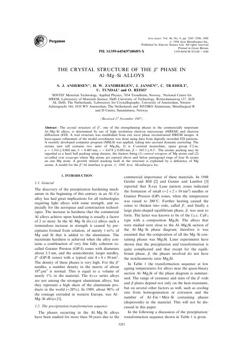
THE CRYSTAL STRUCTURE OF THE b0PHASE INAl±Mg±Si ALLOYSS.J.ANDERSEN1,2,H.W.ZANDBERGEN2,J.JANSEN2,3,C.TRáHOLT2,U.TUNDAL4and O.REISO41SINTEF Materials Technology,Applied Physics,7034Trondheim,Norway,2National Centre for HREM,Laboratory of Materials Science,Delft University of Technology,Rotterdamseweg137,2628 AL Delft,The Netherlands,3Laboratory for Crystallography,University of Amsterdam,Nieuwe Achtergracht166,1018WV Amsterdam,The Netherlands and4HYDRO Aluminium,Metallurgical Rand D Centre,Sunndalsùra,Norway(Received17November1997)AbstractÐThe crystal structure of b0,one of the strengthening phases in the commercially important Al±Mg±Si alloys,is determined by use of high resolution electron microscopy(HREM)and electron di raction(ED).A trial structure was established from exit wave phase reconstructed HREM images.A least-square re®nement of the model coordinates was done using data from digitally recorded ED patterns.A recently developed computer program(MSLS)was applied,taking into account dynamic scattering.The atomic unit cell contains two units of Mg5Si6.It is C-centred monoclinic,space group C2/m, a=1.51620.002nm,b=0.405nm,c=0.67420.002nm,b=105.320.58.The atomic packing may be regarded as a hard ball packing using clusters,the clusters being(1)centred tetragons of Mg atoms and(2) so-called twin icosacaps where Mg atoms are centred above and below pentagonal rings of four Si atoms an one Mg atom.A growth related stacking fault in the structure is explained by a de®ciency of Mg atoms.A model for the b0/Al interface is given.#1998Acta Metallurgica Inc.1.INTRODUCTION1.1.GeneralThe discovery of the precipitation hardening mech-anism in the beginning of this century in an Al±Cu alloy has had great implications for all technologies requiring light alloys with some strength,and es-pecially for the aerospace and construction technol-ogies.The increase in hardness that the commercial Al alloys achieve upon hardening is usually a factor of2or more.In the Al±Mg±Si(6xxx)alloys such a tremendous increase in strength is caused by pre-cipitates formed from solution,of merely1wt%of Mg and Si that is added to the aluminium.The maximum hardness is achieved when the alloy con-tains a combination of very®ne fully coherent so-called Guinier Preston(GP-I)zones with diameters about2.5nm,and the semicoherent,larger needles, b0(GP-II zones)with a typical size4Â4Â50nm3. The density of these phases is very high.For the b0 needles,a number density in the matrix of about 104/m m3is normal.This is equal to a volume of nearly1%in the material.The6xxx series alloys are not among the strongest aluminium alloys,but they represent a high share of the aluminium pro-ducts in the world(H20%).In1989,about90%of the tonnage extruded in western Europe,was Al±Mg±Si alloys[1].1.2.The precipitation/transformation sequenceThe phases occurring in the Al±Mg±Si alloys have been studied for more than50years due to the commercial importance of these materials.In1948 Geisler and Hill[2]and Gunier and Lambot[3] reported that X-ray Laue pattern zones indicated the formation of small(H2Â2Â10nm3)needles or Guinier Preston(GP)zones,when the temperature was raised to2008C.Further heating caused the zones to thicken into rods,called b',and®nally a large plate-shaped equilibrium phase,b,was seen to form.The latter was known to be of the f.c.c.CaF2 type with a composition Mg2Si.The alloys that were studied were close to the Al±Mg2Si section of the Al±Mg±Si phase diagram;therefore it was assumed that the composition of all the Mg±Si con-taining phases was ter experiments have shown that the precipitation and transformation is quite complicated and that except for the equili-brium phase,b,the phases involved do not have the stoichiometric ratio Mg2Si.In Table1the transformation sequence at low ageing temperatures for alloys near the quasi-binary section Al±Mg2Si of the phase diagram is summar-ised.The range of existence and sizes of the b'rods and b plates depend not only on the heat-treatment, but on several other factors as well,such as cooling rate from homogenisation or extrusion and the number of Al±Fe(+Mn)±Si containing phases (dispersoids)in the material.This will not be dis-cussed in this paper.In the following a discussion of the precipitation/ transformation sequence shown in Table1is given.Acta mater.Vol.46,No.9,pp.3283±3298,1998#1998Acta Metallurgica Inc.Published by Elsevier Science Ltd.All rights reservedPrinted in Great Britain1359-6454/98$19.00+0.00 PII:S1359-6454(97)00493-X32831.2.1.Atomic clusters.After rapid cooling from homogenisation or extrusion the material is super-saturated with Mg and Si.Due to the higher solubi-lity of Mg in Al,when stored at room temperature or heated,Si ®rst goes out of solution and forms small clusters,but there are also some indications of clustering of Mg [5].The nucleation of Si-clusters will occur at quenched-in vacancies at temperatures as low as À508,below which the vacancy movement becomes very low [6].Storing or heating above À508will cause Mg to di use to the clusters,and Mg±Si phases will pre-cipitate.The di usion of Mg to the Si clusters has been veri®ed through APFIM [5,7]where the ratio of Mg/Si in the average cluster was found to increase with time when heated at 708.Since the number of Si clusters formed will be important for the precipitation of the strengthening GP zones,the storing time at a low temperature before arti®cial ageing is important concerning the material proper-ties.1.2.2.GP zones and the b 0phase .The ®rst phase to precipitate on the small clusters is the GP zones.Based on a TEM study of Al±Mg 2Si [8]Thomas proposed a model for these particles;Mg and Si replace Al in such a ratio that the occupied volume is about the same.He proposed a simple substi-tution along 110-directions with strings of atoms in the sequence Mg±Si±Mg±Mg±Si±Mg.Here two di-ameters of Mg (2Â0.32nm)and one of Si (0.235nm)amounts to 0.874nm,as compared with three diameters of Al (0.859nm).In more recent research the evolution of GP zones in several Al±Mg 2Si alloys was studied by calorimetry [6],in 6061by calorimetry and TEM [5],and by atom-probe ®eld-ion microscopy (APFIM)and TEM/HREM [5,7].These works support the view that there are at least two phases in the size range of the GP-zones,called GP-I and GP-II.For the GP-I type the size is in the range 1±3nm.The crystal structure is unknown.The zones are fully coherent and probably have a spherical shape.Dutta and Allen [9]observed by TEM small spot-like features of ``unresolved''shape of about 2.5nm that should be the GP-I zones.Particles investigated by APFIM [5]with comparable dimensions to these zones seem to have Mg/Si ratios usually less than 1.This composition is therefore di erent from that of the model proposed by Thomas [8].The GP-II zone is the same phase as the currently investigated b 0phase.This phase has the shape of ®ne needles,typically about 4Â4Â50nm 3when the material is in the aged-hardened condition [7,10].In this condition the number density of the nee-dles is high;typically 104/m m 3[10].The b 0phase is fully coherent only along the b -axis.Edwards et al.[7]managed to determine the unit cell of the b 0phase by electron di raction.It was found to be a monoclinic C-centred structure with a =0.153420.012nm,b =0.405nm,c =0.68320.015nm,b =10621.58.The b -axis is along the needle-axis.It is the full coherency of GP-I zones,the semi-coherency of the GP-II zones together with their high number densities that introduce in the alu-minium matrix strain and resistance against move-ment of dislocations,that gives the material its mechanical strength.1.2.3.The b 'phase .The next phase in the trans-formation sequence after the GP-I zones and the b 0phase is the b 'phase.This has a lower Mg/Si ratio than the equilibrium b phase.Lynch et al.found by X-ray microanalysis evidence for a ratio of Mg/Si in the b 'rods in an overaged material to be about 1.73[11],while Matsuma et al.[12]later determined the ratio to be about 1.68.For materials with excess silicon relative to Al±Mg 2Si there may be very small precipitates also of the b 'and a so-called B 'phase that is richer in silicon,or even Si particles [4].Because of this such particles with sizes comparable to b 0[7,4]may be mistaken for the b 0phase.The b 'and the B 'phase are reported as having the hexa-gonal unit cells a =0.705nm,c =0.405nm and a =0.104nm,c =0.405nm,respectively.In Refs [7,4]the relative number of b 0as compared with the smallest b '(and B ')particles was not deter-mined.It was recently suggested that b 'is a h.c.p.structure with a =0.405nm,c =0.67nm [12,13].1.2.4.The b phase.The b phase is the equilibrium phase in this system.It is the only phase up to now with a known structure.It is a CaF 2type f.c.c.structure with a =0.639nm having formula Mg 2Si.The structure may be described as strings of three atoms,Mg±Si±Mg,on the corners and faces of a cube,directed along the diagonals.Table 1.The evolution of Mg±Si phases near the quasi-binary section Al±Mg 2Si (top to bottom)Transformation/precipitation sequence Crystal type Size (nm)Composition Clusters of Si and fewer of Mg unknown unknown Si (Mg)Clusters containing Si and Mg unknown unknown Mg/Si <1Coherent spherical GP-I zonesunknown H 1±3Mg/Si H 1Semi-coherent GP-II zones (b 0needles)monoclinic H 4Â4Â50Mg/Si r 1b 'rods (and B 'rods)hexagonal H 20Â20Â500Mg/Si H 1.7b -Mg 2Si platescubicmicronsMg/Si =2The B 'phase is observed with alloys having excess Si relative to Al±Mg 2Si.It contains more Si than b '[4].ANDERSEN et al.:Al±Mg±Si ALLOY32841.3.SummationSumming up the information above,it appears that the phases that evolve from the very®ne Si-clusters into coarser particles take up progressively more magnesium during the coarsening and trans-formation processes,until an equilibrium compo-sition Mg2Si for the b phase®nally is reached.In this paper we report the structure determi-nation of the b0phase,which must be one of the important hardening phases in the commercial6xxx alloys.The technique used in the structure determi-nation is the through focus exit wave reconstruction technique in high resolution electron microscopy,in combination with quantitative electron di raction.2.EXPERIMENTAL2.1.Material and sample preparationThe as-received material was in the shape of extruded sections.It was supplied by HYDRO Aluminium AS(Sunndalsùra).The composition of the material was Al±0.2Fe±0.5Mg±0.53Si±0.01Mn (wt%).The material is from the same batch and extruded sections as investigated in Refs[10,14], there labelled as A and C,respectively.Specimen preparation and location in the extruded section of the samples for TEM are described in Refs[10,14]. Prior to the arti®cial ageing(5h at1858)the ma-terial had undergone a rather standard processing for an extrusion product.After the jet-polishing, specimens were stored in methanol.Most of the TEM experiments were performed within a day after specimen preparation.2.2.TEM equipment and experimental dataAll TEM work was performed using a PHILIPS CM30-ST/FEG electron microscope operated at 300kV.The microscope is equipped with a Photometrix1024Â1024slow scan CCD camera (12bits dynamical range),enabling a linear record-ing of HREM and ED puter control of the CCD camera and the microscope is handled with a Tietz software package.In this way series of 15±20HREM images with focus increments of typi-cally 5.2nm were recorded for each exit wave reconstruction.For the high resolution work suitable aluminium grains were selected and tilted into a h100i zone axis.HREM images were recorded at room tem-perature on as thin areas as possible,typically4±10nm.Needles were selected that could be viewed along their[010]zone axis.In this situation,the needles usually extend through the whole thickness of the specimen,such that no image blurring occurs due to overlap with the matrix.For a single image, the exposure time was usually about1s.For the di raction experiments a small spot-size (5±10nm)was used with exposure times of1±5s. Two zone-axes of the needles were chosen;[010]and[001].For the latter,the aluminium grain was tilted to a h310i zone axis,where statistically one out of six needles is in the correct orientation. Many of the needles contain stacking-faults or sec-ond phases.For a reliable structure determination it is important that the area where a di raction pat-tern is taken is free of defects.Given the resolution of the microscope it should be relatively easy to select single crystalline b0particles.However,to prevent the rapid contamination of the illuminated area that is typical for this kind of specimen at room temperature,the specimen was cooled to about100K.The sample cooling holder has a much poorer mechanical stability resulting in such a loss of resolution that selection of single crystal b0particles was di cult.Because of this ED pat-terns were taken from each particle encountered. Therefore quite many di raction patterns had to be discarded because of streaking and twinning prob-ably caused by the stacking-faults or sometimes extra spots caused by a intergrown phase that was determined to be b'.Five[010]di raction patterns were selected.For the[001]zone axis there is a greater chance of``cross-talk''due to more overlap of the matrix with the crystal,and suitable di rac-tion patterns for the re®nement were more di cult to®nd.Here®ve of the16recorded patterns were from the correct projection or particle.Only two of these patterns could later be re®ned.In addition to the problem with overlap spots from the b'phase, the reason was also the strong interference with the aluminium matrix in this projection that made sub-traction of the background di cult.The thickness of the investigated areas were somewhat larger for the di raction experiments than for the HREM ex-periments.The subsequent re®nements showed that the thickness usually exceeded10nm.In Fig.6, parts of two of the digitally recorded di raction images are shown.This®gure also shows some streaking caused by oversaturation of the CCD camera,which was not equipped with over¯ow pro-tection.The streaks and the aluminium di raction re¯ections were excluded from the images prior to data reduction.The exit wave reconstruction of the HREM focus series were done with a software package based on algorithms developed by Van Dyck and Coene[15±17].Given the coherency of the presently available ®eld emission guns the structural information in ordinary HREM images goes well beyond the point-to-point resolution in the electron microscope. The reconstruction method takes advantage of the knowledge about the transfer function,e.g.how the microscope optics distorts the electron wave after leaving the crystal(the exit wave)on its way to the image plane.This distortion is also a function of defocus.A series of HREM images are recorded at intervals of known defocus.The amplitude and phase information that is mixed up in the HREM images is retrieved through digital processing,andANDERSEN et al.:Al±Mg±Si ALLOY3285corrections for focus and spherical aberration are done.Furthermore,since typically15±20images are used in the reconstruction a considerable reduction in noise is attained.The exit wave is thus independent of various aberrations of the electron microscope, but it is still dependent on the specimen thickness. Only for very small specimen thicknesses is the exit wave very similar to the projected potential,viz.the projected atomic structure.For thicker sections,e.g. more than about10nm for the presently presented exit wave image,the local contrast in the exit wave can be quite di erent from the local scattering poten-tial.Thus,for such thicknesses a higher brightness at a certain point in the phase image of the exit wave as compared to other points,does not have to imply the presence of a locally more strongly scattering atom at this point.The good news is that the positions of the bright dots should correlate well with the location of the atoms.In the presently used electron microscope the res-olution is enhanced from0.20nm to about0.14nm. The HREM images presented in this work are recombined exit wave phase images.See Coene et al.[17],Zandbergen et al.[18]and Op de Beeck et al.[19]for examples and discussion of the method. The re®nement of the structure was done using the computer programme package MSLS[20].The CCD images with the di raction patterns were cor-rected for the¯at®eld(variation in the pixel sensi-tivity)and over¯ow during read-out of the CCD camera.Spurious X-ray signals and the Al di rac-tion spots were omitted.Automatic indexing and data reduction on the patterns were done.The obtained two-dimensional indices of the images were next transformed into the correct hkl indices so that the di raction data sets could be combined. MSLS was used for re®nement of the trial structure coordinates as obtained from the reconstructed exit wave.This program re®nes coordinates based on the least-squares procedure using the multi-slice al-gorithm to account for the dynamic di raction.The parameters re®ned were the thickness,the scaling factor,the centre of the Laue circle for each of the data sets,and the atomic coordinates and tempera-ture factors.The R-value used as measure of the correctness of the structure is de®ned as R=a(I calcÀI obs)2/a(I obs)2.Only the signi®cant re¯ections(I obs>2s(I obs))were used.R-values between2and6%are being quoted for the most reliably determined structures.3.RESULTS/DISCUSSION3.1.Conventional HREM/TEMConventional TEM shows the interior of the Al grains to mainly contain particles having a®ne nee-dle shape.The needles lay along h100i Al directions. Figure1gives an example.It is a bright®eld image in an Al h100i zone axis where the needles clearly point in two normal directions.The dark spots are needles pointing in the viewing direction.The exper-imental di raction patterns as well as HREM images show that the needle shaped particles mostly are of one kind,the monoclinic phase that is usually referred to as the b0phase.Figure2shows a HREM image with one such needle.Such images show the precipitates to be coherent along the nee-dle direction(their b-axis)with a h100i Al direction. This con®rms that their cell parameter is the same as aluminium,b=0.405nm.Many of the b0precipitates were found to con-tain stacking faults.In some precipitates an inter-growth of b0with another phase was observed.It is most probably the b'phase which has the hexago-nal axis along the needle direction.Sometimes this phase was found to exist alone.The cell parameter a=0.705nm has been con®rmed from exit wave simulated images.These images will be published later.In the same material coarser rods of the b' phase have earlier been investigated;It was reported that they nucleate on®ne Al±Fe±Si particles[14].It may be expected that much of the b'particles nucle-ate on b0since with longer arti®cial ageing times the micro-structure will contain an increasing amount of rods of b'.By selected area electron dif-fraction the coarse b'phase in this material was determined to have a hexagonal structure with a H0.71nm,c H0.41nm.The a-axis therefore®ts well with the phase intergrown with b0.The struc-ture of the small and large b'is therefore probably the same.We did not observe any B'phase in the material.3.2.Elemental analysis of the b0phaseWe performed several X-ray analyses of the small precipitates with the spot along the needle axis. Due to the very thin specimen areas(10±40nm)the spectra obtained should in principle not be signi®-cantly in¯uenced by absorption in the specimen, which is the most important reason for deviations from the actual concentration.In spite of the small size of the spot(1±2nm),there was always an Al peak present in the spectrum,of varying height. This is partly caused by stray electrons travelling down the column of the electron microscope which are not focused with the rest of the electrons in the beam probe and therefore many hit aluminium. Secondly,because during analysis the beam is par-allel to the needle axis,i.e.to the[010]zone axis of b0,this implies an e ective beam broadening by the elastic scattering of some electrons into aluminium. For some of the recordings there is also an e ect of specimen drift during recording.Another e ect is the contamination layer and the(aluminium)oxide layer on the surface of the particle which primarily contains Al.The EDS experiments could therefore not rule out that some Al is contained in the precipitate.As a standard for determining the K-ratios a mineral forsterite was used whose mainANDERSEN et al.:Al±Mg±Si ALLOY 3286components are MgO and SiO 2with a composition so that the Mg/Si atomic ratio is 2.Not taking into account the possible systematic deviations,the EDS experiments indicated that the atomic ratio for Mg/Si was close to or even below 1.The accuracy of these measurements were on the order of 10%.However,they ruled out the earlier accepted ratio of 2for the b 0phase.EDS measurements were also performed on larger particles of the b 'and b -Mg 2Si phases which had been extracted from the alu-minium matrix.These phases gave compositions near the expected,as listed in Table 1.The accuracy here was much better for thin sections since the alu-minium matrix could be avoided entirely.3.3.Exit wave reconstruction3.3.1.The unit cell.Coherency of the b 0phase with the matrix .In Fig.3a reconstructed exit wave (phase)of a b 0particle in the [010]orientation embedded in aluminium is shown.The b 0[010]direction is parallel to a h 100i type aluminium zone axis and is along the needle.Atomic columns in the viewing direction in the image appear as bright dots.The columns in the Al matrix are clearly resolved;in this projection the separation between nearest neighbor columns are 0.2025nm,or half the Al unit cell length.Due to the face centering of alu-minium the nearest neighbor atom columns are also shifted 0.2025nm in the viewing direction relative to each other.In the ®gure circles are drawn that indicate the two di erent height positions of the atoms in the viewing direction.The lattice image of the Al matrix changes over the image due to local variations in tilt.The b 0unit cell is outlined in the particle.Due to the C-centering,the a -axis is twice the apparent periodicity.By calibrating the magni®cation of the image using the aluminium lattice,the unit cell was established to be a =1.51620.002nm,c =0.67420.002nm and b H 105±1068.HREM of other nee-dles lying in the normal direction (Fig.2)have shown that there is a full coherence between the crystal along the b -axis with the same periodicity as the aluminium matrix;therefore b =0.405nm.In the re®nement of di raction images for this zone axis,the monoclinic angle is calculated.It was found to have a mean value b =105.320.58when averaged over 7di raction patterns.The b 0unit cell is closely related to the alu-minium lattice.From di raction patterns (Fig.5)asFig.1.A typical low magni®cation micrograph of b 0needles in a h 001i Al zone axis.Needles are directed along the three h 100i Al directions and appear therefore point-like (dark spots)in the viewing direction.The needles have a mean diameter of about 4nm,and an average length about 50nm.Alarger b 'rod (white appearance)is directed in the viewing direction in the centre of the image.ANDERSEN et al.:Al±Mg±Si ALLOY 3287well as from the exit wave (Fig.3)the following relationship between the phases can be found; 001 Al k 010 b 0,"310 Al k 001 b 0,230 Al k 100 b 0This relationship is the same as found earlier byEdwards et al.[7].A corresponding super cell in aluminium can be de®ned by real vectors ~ab 0 2~a Al 3~b Al ,~b b 0~c Al ,~c b 0 À32~a Al 12~b Alwith respective lengths 1.46,0.405and 0.64nm witha monoclinic angle of 105.38.Half of this super cellis outlined in Fig.3on the left side of the b 0par-ticle.The super cell is also C-centred monoclinicsince two neighbor corners of the half cell along ~ab 0fall on Al atoms in di erent layers.The unit cell for b 0is slightly larger than this Al super cell;3.8%along ~ab 0and 5.3%along ~c b 0.The half super cell (asymmetric unit)contains 11Al atoms.The coherency between b 0and aluminium aids in quantifying the shift of the stacking fault (sf)in the particle that is indicated in Fig.3;By using the Al matrix as reference it can be veri®ed that Al atoms at the left interface,at the upper part (e.g.near the white corners of the unit cell of b 0)are at a di er-ent height relative to similar atoms of b 0on the lower part (here with a black ®ll){.This is illus-trated by the two outlined (half)super cells in the Al matrix that are related to the unit cell of b 0in the upper and lower part of the particle.These super cells are shifted a vector a Al [101]/2relative to each other,which indicates that the shift across the stacking fault in the particle is nearly the same.This shift vector is a Burgers vector of the most common dislocation in aluminium.A model of the fault is given in Section5.Fig.2.Ordinary HREM image of b 0-needle in an h 001i zone axis in Al.The c -axis of the needle is in the plane,and the coherency with h 100i Al in the needle direction is evident.As expected,there is no exact zone axis of b 0along the viewing direction h 001i Al zone axis.The left part of the picture was fourier ®ltered;A high pass ®lter was applied to the upper part and a low pass ®lter to the lower partto extract the periodic information from Al (upper)and the b 0-phase (lower)only.{Alternatively,assume the corners of the outlined unit cells of b 0on each side of the stacking fault to be at thesame heights along ~cb 0.The atoms to the left of Ðand in the matrix outside Ðthese corners must then necessarily have similar heights,since the atomic con®guration and distances to the left of these corners are similar,whether above or below the stacking fault.This assumption must be wrong;When keeping track of the atomic columns in the matrix it leads to the conclusion of an Al atom being at two heights at the same time.Therefore,the corners ofthe unit cells along ~cb 0have di erent heights across the stacking fault.ANDERSEN et al.:Al±Mg±Si ALLOY3288In Fig.4the coherency between the two phases can be studied in more detail.This image is a Fast Fourier Transformation (FFT)of part of Fig.3.Only the lower part of the b 0precipitate is included to reduce streaking caused by the stacking fault.After applying a Fourier ®lter (selecting the con-tents inside the circles superposed on the FFT of Fig.4)the Al re¯ections plus the 610,610,403and 403re¯ections of b 0contribute to the image in Fig.5.The white arrows indicate interface dislo-cations between the particle and matrix.For example,the b 0(601)lattice planes with a spacing d 601=0.211nm are parallel with the Al (200)planes with a spacing of 0.203nm.Therefore,one interface dislocation is expected for each 25Al d 200spacings (normal to the [100]axis in the ®gure).Similarly,for the 403planes,for each 20Al d 020spacing one expects an interface dislocation.The spacings between dislocations observed in Fig.5are di erent from the theoretical ones.The reason for this devi-ation is probably variation in local strain in the particle caused by the stacking fault.Although the exact dislocation is not clear in the image,a matrix dislocation found (marked ``d '')also complicates the situation concerning the mis®t dislocations.This dislocation is found to have a Burgers vector b =0.5a Al [101],as was found when a Burgers vec-tor loop was performed around the particle.This is indicated by the open arrow (d).In Fig.6,two ex-perimental di raction images from the [010]and [001]zone axes are shown.The b 0610and 403re¯ections that coincide with the 200and 020Al matrix re¯ections can also be seen in Fig.6(a).In Fig.6(b)the perfect coherency relation of the (010)lattice planes of the b 0phases with (200)lattice planes can be seen from the overlap of the respect-ive di raction spots.3.3.2.Extraction of the atomic coordinates for b 0from the exit wave images .Figure 7(a)is an increased magni®cation of part of Fig.3.Here the atomic columns are represented as white dots.From this image the atomic positions were esti-mated using the following assumptions:(1)The number of atoms in the unit cell is 22,just as the number of atoms in the similar super cell in aluminium.The number ®ts the apparentnumberFig.3.Phase of an reconstructed exit wave of a typical b 0needle in Al is shown.The needle is viewed head-on along its [010]axis,and along an Al h 001i zone axis.Atomic columns appear white.The b 0unit cell and half the corresponding super cell in Al are outlined.Similarly ®lled circles in the matrix or in the precipitate are atoms (Al or Mg)at the same height.A stacking fault (sf)is indicated.The shiftacross the stacking fault can be determined to be a Al [101]/2.ANDERSEN et al.:Al±Mg±Si ALLOY 3289。
Search for a new state of matter – the Quark-Gluon Plasma一个物质–夸克胶子等离子体的新状态搜索 43
-- multi-parton dynamics (recombination or coalescence or …)
-- Hydrodynamics (constituent quarks ? parton dynamics from gluons to constituent quarks? )
Nucleus-Nucleus Collisions and Volcanic Eruption
Volcanic high pT -- Strombolian eruption
Volcanic mediate pT – Spatter (clumps)
6
Volcanic low pT – Bulk matter flows
Evidence for Multi-parton Dynamics in Hadronization of Bulk Partonic Matter at RHIC
Huan Zhong Huang (黄焕中) Department of Physics and Astronomy
University of California Los Angeles
Rafelski+Danos, Molnar+Voloshin …..) Quark Recombination – (R.J. Fries et al, R. Hwa et al)
13
Constituent Quark Scaling
Constituent (n) Quark Scaling -- Meson n=2 and Baryon n=3 grouping
p td d td p N y d 2 1 π p td dtd p N 1 y i 12ic vo s ψ R () i)1( 0
电沉积法

Applied Surface Science 277 (2013) 105–110Contents lists available at SciVerse ScienceDirectApplied SurfaceSciencej o u r n a l h o m e p a g e :w w w.e l s e v i e r.c o m /l o c a t e /a p s u scElectrodeposited Ag nanoparticles on TiO 2nanorods for enhanced UV visible light photoreduction CO 2to CH 4Dan Kong,Jeannie Ziang Yie Tan,Fei Yang,Jieliang Zeng,Xiwen Zhang ∗State Key Laboratory of Silicon Materials,Department of Materials Science and Engineering,ZheJiang University,Hangzhou 310027,PR Chinaa r t i c l ei n f oArticle history:Received 26February 2013Received in revised form 31March 2013Accepted 3April 2013Available online 17 April 2013Keywords:Ag nanoparticle Electrodeposition CO 2photoreduction TiO 2nanorodsa b s t r a c tWe employed the double-potentiostatic methodology to electrodeposit Ag nanoparticles on oriented single-crystalline rutile TiO 2nanorods synthesized by hydrothermal method.The synthesized composites were used as the photocatalyst to reduce CO 2to CH 4under UV irradiation,and tested by SEM,XRD,TEM,XPS,UV–vis and photoluminescence.Deposition with Ag nanoparticles was observed to enhance the pho-tocatalytic activity (≈1.5–2.64mol (g catal h)−1)up to 5times with respect to undecorated TiO 2nanorods (≈0.5mol (g catal h)−1).The increase in the CH 4yield was correlated with the surface morphology and structure of TiO 2nanorods.© 2013 Elsevier B.V. All rights reserved.1.IntroductionAs is known to everyone,carbon dioxide (CO 2)is one of the major greenhouse gases in recent years because the emissions have sharply increased from fossil fuel combustion over the past few centuries [1].CO 2photoreduction is one promising strategy to switch the rising emissions to renewable energy products such as CO,methane (CH 4),methanol (CH 3OH),formaldehyde (HCOOH)[2].Many researchers have reported that titanium dioxide (TiO 2),TiO 2nanocomposites [3]and other metal oxide catalysts can con-vert CO 2[1,4]to methane or methanol in the presence of water.TiO 2is almost a perfect photocatalyst due to its excellent chemical sta-bility,easy operation,low cost and high catalytic activity.However,the relatively high energy bandgap (3.2eV)limits TiO 2only operat-ing under UV irradiation with a wavelength shorter than 387.5nm [4].An effective resolution to improve the photocatalytic activity is modifying TiO 2by doping with metal impurities,such as noble and transition metals [5–8].For instance,Ag has successfully decorated TiO 2for increasing yields of several photocatalytic reactions [9–14].The advantages of Ag doped or deposited on TiO 2are (i)to modify the surface morphologies and structures of TiO 2,(ii)to improve the electron–hole separation by performing as electron traps [15],(iii)to increase the surface electron activity by localized surface plasma Resonance [16,17].∗Corresponding author.E-mail address:zhangxw@ (X.Zhang).Koˇc i et al.[12]prepared Ag-enriched TiO 2powders by sol–gel process controlled in the reverse micellar environ-ment.The catalysts were tested in CO 2photocatalytic reduction under UV irradiation,where the highest yields of methane was 0.38mol g catal −1after 24h of UV irradiation.The Ag-doped sol–gel TiO 2powder possessed higher photocatalytic activity than pure TiO 2.Xingtian Yin et al.[17]probed that Ag–TiO 2nanocomposites were prepared at low temperature in polyethylene glycol solution.TiO 2powders with different Ag contents were employed to decom-pose methyl orange under UV.The rapid separation of photoexcited charge carriers and the surface Plasmon effect of Ag nanoparticles in the visible region contributed to a better photocatalytic activity of samples.However,the sol–gel method to preparing Ag–TiO 2nanocom-posites is not so successful,as the particle size and the spatial distribution is not homogenous compared to the electrochem-ical deposition [18–21].Until now,several methods have been employed such as double potential pulses [20],potential step [22],or cyclic voltammetry scan [23].Depositing Ag nanoparticles onto substrates by double-potentiostatic method is rarely recorded.The double-potentiostatic method can realize a quick nucleation and slow growth under the high nucleation potential and low precur-sor concentration,maintaining a suitable growth rate and obtaining uniform and dense metallic nanoparticles [24,25].In our report,Ag nanoparticles were deposited on TiO 2nanorods by double-potentiostatic methods under different nucleation potentials.Hydrothermal method was used to grow TiO 2nanorods on transparent conductive fluorine-doped tin oxide (FTO)sub-strates.The prepared catalysts were evaluated by photoreduction0169-4332/$–see front matter © 2013 Elsevier B.V. All rights reserved./10.1016/j.apsusc.2013.04.010106 D.Kong et al./Applied Surface Science277 (2013) 105–110CO2under UV irradiation.The results showed that TiO2decorated with Ag nanoparticles improved photocatalytic activity,and Ag deposited TiO2under−1.0V nucleation potential had better perfor-mance for the better size variation and uniform spatial distribution compared to other nucleation potentials.2.Experimental2.1.Preparation of photocatalystsTiO2nanorods were prepared by the hydrothermal method on FTO substrates following the report[26].In the beginning,FTO sub-strates(F:SnO2,Tec15,10 m,Hartford Glass Company)were ultrasonically cleaned for60min in a mixture of deionized water, acetone and2-propanol with volume ratios of1:1:1.Tecdeionized water and concentrated hydrochloric acid(36.5–38%by weight) were mixed(ratio1:1)to reach a total volume of480mL,stirred at ambient conditions for15min,and then stirred for15min after the addition of8mL of titanium butoxide(97%Aldrich).The pre-cursor solution immersed FTO substrates,placed at angle against the wall of the Teflon-liner with the conduction side facing down. TiO2nanorods were growing on FTO at150◦C for20h in an elec-tric oven.After that,the FTO substrates were removed,rinsed completely with deionized water overnight and dried in ambi-ent conditions.0.1M KNO3,0.2mM sodium citrate(C6H5Na3O7) and0.05mM AgNO3made up of aqueous electrolyte.The double-potentiostatic method was used on an electrochemical workstation (ES550,Gaoss Union Technology Co.,Ltd.,Wuhan,China).Based on linear sweep voltammogram of TiO2nanorodsfilm from0.2V to −1.5V at−0.05V/s,the nucleation potential was chosen to deposit Ag atoms ranging from−1.4V to−0.8V for100s and the growth potential was−0.2V for2400s at room temperature(28±1◦C)in a standard three-electrode system.FTO coated with TiO2nanorods was used as working electrode,Pt plate as counter electrode and saturated calomel electrode(SCE)as reference electrode.2.2.Characterization of photocatalystsScanning electron microscopy(SEM,Hitachi S4800)was employed to characterize the surface morphologies of TiO2 nanorods and silver nanoparticles.The crystal structure of the as-prepared samples was examined by X-ray diffraction(XRD)in a X’Pert PRO diffractometer using Cu K␣radiation( =1.5406˚A) from20◦to80◦at a scanning speed of2◦/min.The elemental composition of as-prepared samples was analyzed by X-ray photo-electron spectroscopy(XPS)in a VG ESCALAB Mark II instrument using Mg-K␣excitation source.The amount of spectra,recorded at normal emission with pass energies of0.8eV at300W,was collected from the area under the curve of Ag nanoparticles on TiO2film according to the Handbook of X-ray Photoelectron Spec-troscopy(Physical Electronics Division,Eden Prairie,Minnesota, USA,1979).Microstructure was characterized by transmission electron microscopy(TEM)image on a Philips CM200TEM with an acceleration voltage of160kV.The absorption spectra were recorded with a TU-1901UV–vis spectrophotometer by using bare FTO coated glass as the reference.The photoluminescence spectra were carried out on a FLS920fluorescence spectrometer(Edinburg Instruments Ltd.)using a325nm UV xenon lamp as the excitation source.2.3.Photocatalytic reduction experimentsPhotoreduction of CO2was conducted in a quartz reactor with the as-prepared TiO2film placed at the center of the container bottom.The ultraviolet light irradiation system consisted four 8W UVA lamps with a wavelength of365nm(average intensity:3.25mW cm−2,measured by UVX radiometer,UVP)and located in two groups on opposite sides of the container.The details of the photoreduction process and analytical methods were described in our previous report[27].Ultra-pure gaseous CO2(Air Products, 99.995%)wasflowed through deionized water into the reactor for 30min beforeflowing into the reactor for30min to degas the air from the reactor were automatically analyzed by chromatography (GC/FID,Thermo-Fisher,Trace GC)once an hour during the whole 8h reaction time.Methane was the main organic product from the reactor and the reactor and carbon monoxide was occasionally measured within the detection limits of our method(∼200ppb). Therefore,the direct measure of activity toward CO2photoreduc-tion is referenced to the methane yield.The results were compared with our previous work[27].3.Results and discussionFig.1A(a)shows the linear sweep voltammogram of the elec-trolyte from0.2V to−1.5V at the scanning speed of−0.05V/s. The scanning peak at about−0.6V referred to the electrochemi-cal reduction of Ag nanoparticles[28].The related potential–time and current density–time curves were shown in Fig.1A(b)and (c)respectively.Double-potential methods were implemented to study influence of the nucleation potential for Ag nanoparticles. Such short nucleation periods(100s)and long growth periods (2400s)ensured quick nucleation and slow particle growth pro-cess[29].As the nucleation potential was more negative than −0.8V,the current densities were higher in Fig.1A(c).When the nucleation period prolonged with higher nucleation poten-tial,the Ag precursor concentration was reduced at higher rate. Then the low precursor concentration restrained the growth of the nuclei[21,30].Thus,nucleation potential and deposition time was the key to control the size and diameter of Ag nanoparti-cles if the precursor solution were determined.In other words, the nucleation and growth process of Ag nanoparticles could be realized the controllability of size and diameter by the double-potential.This phenomenon could be further confirmed with SEM.Fig.1B shows the SEM image of the as-prepared TiO2nanorods after deposition with Ag nanoparticles.The top view showed that the nanorods were tetragonal and the lengths being approximately 2m.The cross-sectional views(b–e)exhibited a uniform distri-bution of the metal on the surface of the nanorods and the size and diameter of nanoparticles diminishing with increasingly nega-tive nucleation potential.The number of nanoparticles increased as more positions were invoked by increasing the nucleation poten-tial.When the nucleation potential reached−0.8V,agglomeration (van der Waals interactions)or aggregation(chemical bands)of Ag nanoparticles at the top part of the nanorods was observed as shown in Fig.2b.In addition,the high nucleation potential had also destroyed the morphology of TiO2nanorods in Fig.2b.High-resolution XPS spectra of Ag(3d)were displayed in Fig.1C. The peaks observed at363.3and369.4eV referred to Ag3d3/2and 3d5/2electronic states of metallic silver respectively.The6.0eV difference between the binding energy of the peaks was also the characteristic of metallic Ag3d states[6,31].There was no peak for oxidized silver corresponding to Ag2O or AgO observed in the full XPS spectra of all the samples.Thus,XPS data together with SEM images,suggested that Ag nanoparticles were deposited on the nanorods.When the nucleation potential increased from−1.2V to−0.8V,XPS intensity was also increasing,indicating that differ-ent content of Ag nanoparticles were formed on the surfaces.There was no XPS spectra of the Ag component deposited under nuclea-tion potential of−1.4V,which was because that Ag nanoparticles were too small to be observed by XPS.D.Kong et al./Applied Surface Science277 (2013) 105–110107Fig.1.(A)(a)Linear sweep voltammogram of TiO2nanorods from0.2V to−1.5V at−0.05V/s,(b)potential–time curves(−0.8V,−1.0V,−1.2V,−1.4V for100s respectively and−0.2V for2400s)and(c)the corresponding current density–time curves of the double-potentiostatic electrodeposition process,(B)SEM images of top view(a)and cross-sectional view(b)of Ag nanoparticles deposited on TiO2nanorods at nucleation potentials of−0.8V,−1.0V(c),−1.2V(d)and−1.4V(e);(C)XPS spectra of TiO2 nanorods after Ag nanoparticles deposition under the different nucleation potentials.Fig.2.(A)XRD patterns of the TiO2nanorods before(a)and after(b–d)Ag electrodeposition under different nucleation potentials as shown in the legend and(B)TEM pattern and(C)HRTEM pattern of TiO2nanorods after Ag electrodeposition under the nucleation potention of−1.0V.108 D.Kong et al./Applied Surface Science 277 (2013) 105–110Fig.3.(A)UV–vis spectra of TiO 2nanorods before and after Ag deposition at differ-ent nucleation potentials,(B)Fluorescence spectra of pure and Ag–TiO 2nanorods under different nucleation potentials.In Fig.2A XRD patterns showed TiO 2nanorods were rutiles with growth axis in the (101)and (002)directions.The nanorods before and after electrodeposition showed the similar XRD curves.The absence of Ag component on TiO 2nanorods showed that Ag did not enter the TiO 2lattice [32].Ag-deposited TiO 2nanorods at nucleation potential of −1.0V were further investigated by TEM as shown in Fig.2B and C.It clearly displayed that Ag nanoparticles amorphously covered TiO 2nanorods with a diameter of 200nm in Fig.2B.Fig.2C shows the high resolution TEM image of the Ag-TiO 2nanocomposites.The spacing between two adjacent lattice fringes were 0.35nm and 0.24nm,corresponding to the (101)plane of TiO 2and the (111)plane of Ag,respectively.The distinguished interface further confirmed the XRD results.The formation of chem-ical bond between TiO 2and Ag nanoparticles was verified by the continuity of lattice fringes between them.Fig.3A shows the UV–vis spectroscopy of the Ag-deposited TiO 2nanorods at the different nucleation potentials.All the samples had higher absorbance intensities than the unmodified TiO 2nanorod films in the range from 300to 400nm.It was observed a red shift and a broadening peak width with increase of nucleation poten-tial between −1.4V and −1.0V.According to the SEM images,the nanorods-deposited Ag nanoparticles at the nucleation potential of −1.0V exhibited a shorter distance between particles and a larger coverage area of particles without agglomeration,suggesting a better-proportioned metal dispersion than other samples.With the condition of unaggregation,the increase of the deposition amount of Ag on TiO 2nanorods with the increasing nucleation potentials had increased the localized surface Plasmon resonance intensity of Ag nanoparticles [6,33,34,16].Thus,the increase of nucleation potentials leaded to the slight red-shift of absorption edge,which contributed to enhancing photoactivity under visible light [35].Fig.4.(A)Sums of methane yield of prepared catalysts at Ag electrodeposition nucleation potentials of −1.0V and −1.2V under UV irradiation (365nm);(B)pho-tocatalytic process:(a)absorbing electron activity and (b)localized surface plasma resonance of Ag nanoparticles effecting carriers transfer process under irradiation.Fig.3B shows the photoluminescence spectra of pure and Ag-deposited TiO 2nanorods.The fluorescence peaks of Ag–TiO 2were the same as pure TiO 2nanorods in the region of 400–450nm.But the sample after Ag electrodeposition at the nucleation poten-tial of −0.8V had another peak in the region of 350–400nm.This was because that aggregating Ag nanoparticles improved the recombination of excited electron–hole pairs [36].The lower inten-sity of Ag–TiO 2nanorods revealed the decrease in recombining electron–hole pairs on metal-loaded TiO 2nanorod surfaces.The positively charged plasmas of Ag nanoparticles attracted electrons in the conduction band of TiO 2and then increased the capability of electron–hole separation [37].However,if the Ag nanoparticles were adjacent to each other,the separation pairs would have been recombining together very soon even under lower energy [38,39].As the nucleation potential of Ag deposition decreased,the cor-responding intensity of the fluorescence decreased.This suggested that the size and the directional distribution of Ag nanoparticles sig-nificantly influenced the rate of e −/h +separation in semiconductor,as well as re-dox reactions.The photocatalytic activity of Ag–TiO 2with the deposited nucleation potentials of −1.2V and −1.0V was compared to that of pure TiO 2nannorods.Fig.4A exhibited the photocat-alytic results in terms of the methane yield versus reaction time.Both Ag-deposited nanorods exhibited much higher methane total outputs (≈1.5–2.64mol (g catal h)−1)than the pure TiO 2(≈0.5mol (g catal h)−1),suggesting the metal-decorated TiO 2nanorods could highly enhance photocatalytic activity.The uni-form distribution of Ag nanoparticles on the nanorods improved the separation of photogenerated electrons,as well as providing more electron traps than pure TiO 2nanorods.In addition,the AgD.Kong et al./Applied Surface Science277 (2013) 105–110109nanoparticles as intermediates were more convenient to carry out photocatalytic reductions at superior rates.Both of them were responsible for the excellent photocatalytic performance of Ag–TiO2nanorods.The photocatalytic process of Ag–TiO2nanocomposites,as shown in Fig.4B,was put forward to discuss the above phenomena in detail.In Fig.4B(a)the electron transferred from the excited TiO2nanorods to Ag nanoparticles under UV light,due to the lower Fermi level of Ag(E f=0.4V)than that of TiO2.Thus,more electrons assembled in the Fermi level of the metal and the whole Fermi level of Ag–TiO2was nearer to the conduction band of the TiO2, which brought better reductive power of nanocomposites[40]. The improved electron–hole separation and the enhanced reduc-tive power contributed to the photocatalytic activity of Ag–TiO2 nanocomposites under UV irradiation.In addition,due to the local-ized surface plasma resonance of Ag nanoparticles,incident light induced an electricfield in metal nanoparticles,and those nega-tive charge plasmas and positive charge plasmas were separated, as shown in Fig.4B(b).Then the negative charge plasmas near the valence band reacted with holes and positive charge plasmas near the conduction band reacted with electrons[27].The electrons transferring through the Ag nanoparticles reacted with absorbed oxidants to produce oxygen radicals(O2•−),which reduced recom-bination probability in TiO2[37].Together,Ag-deposited TiO2 nanorods exhibit much better photocatalytic performance than the pure TiO2nanorods in our report.However,as the nucleation potential increased from−1.0V to−0.8V,the Ag nanopartilces aggregated together,which infringed the photocatalytic process. The possible explanation was that the aggregation improved the probability of holes captured by Ag nanoparticles and recombina-tion of electron–hole pairs,thus the poorer photoreduction activity [40].4.ConclusionThis work demonstrated Ag nanoparticles successfully deposited on TiO2nanorods by electrochemical method,could highly improve the photocatalytic activity.Under the different nucleation potentials the different size and distribution of Ag nanoparticles grew up on TiO2nanorods.Photoreduction activity measurements were evaluated by photoreduction of CO2under UV irradiation.The results showed that Ag–TiO2nanocomposites exhibited higher photocatalytic activity of conversion CO2to CH4 with rates up to 2.64mol(g catal h)−1than that of pure TiO2, possibly due to their specific structures and morphology assisting in the separation of photogenerated electrons and holes.This report might provide new insights into the design and fabrication of advanced photocatalytic materials with complex hierarchical architectures and enhanced photocatalytic activity. AcknowledgementsThis report wasfinancially supported by Key Science and Tech-nology Innovation Team of Zhejiang Province under the grant number2010R50013.In addition,this work wasfinancially sup-ported by University of Nottingham&Zhejiang Collaborative Fund, 2011.“Development of porous TiO2films for carbon dioxide con-version into chemicals and fuels”.References[1]S.C.Roy,O.K.Varghese,M.Paulose,C.A.Grimes,Toward solar fuels:photo-catalytic conversion of carbon dioxide to hydrocarbons,ACS Nano4(2010) 1259–1278.[2]J.Ma,N.Sun,X.Zhang,N.Zhao,F.Xiao,W.Wei,Y.Sun,A short review of catalysisfor CO2conversion,Catalysis Today148(2009)221–231.[3]Q.Zhang,W.Han,Y.Hong,J.Yu,Photocatalytic reduction of CO2with H2O onPt-loaded TiO2catalyst,Catalysis Today148(2009)335–340.[4]ubharatana,D.McMartin,A.Veawab,P.Tontiwachwuthikul,Photocat-alytic process for CO2emission reduction from industrialflue gas streams, Industrial and Engineering Chemistry Research45(2006)2558–2568.[5]X.Feng,K.Shankar,M.Paulose,C.A.Grimes,Tantalum-doped titanium dioxidenanowire arrays for dye-sensitized solar cells with high open-circuit voltage, Angewandte Chemie International Edition121(2009)8239–8242.[6]B.Cheng,Y.Le,J.Yu,Preparation and enhanced photocatalytic activity ofAg@TiO2core–shell nanocomposite nanowires,Journal of Hazardous Materials 177(2010)971–977.[7]B.Xin,P.Wang,D.Ding,J.Liu,Z.Ren,H.Fu,Effect of surface species on Cu-TiO2photocatalytic activity,Applied Surface Science254(2008)2569–2574.[8]V.Vamathevan,H.Tse,R.Amal,G.Low,S.McEvoy,Effects of Fe3+and Ag+ions onthe photocatalytic degradation of sucrose in water,Catalysis Today68(2001) 201–208.[9]M.K.Seery,R.George,P.Floris,S.C.Pillai,Silver doped titanium dioxide nano-materials for enhanced visible light photocatalysis,Journal of Photochemistry and Photobiology A:Chemistry189(2007)258–263.[10]M.S.Lee,S.Hong,M.Mohseni,Synthesis of photocatalytic nanosized TiO2–Agparticles with sol–gel method using reduction agent,Journal of Molecular Catalysis A:Chemical242(2005)135–140.[11]N.Sobana,M.Muruganadham,M.Swaminathan,Nano-Ag particles doped TiO2for efficient photodegradation of direct azo dyes,Journal of Molecular Catalysis A:Chemical258(2006)124–132.[12]K.Koˇcí,K.Matˇe j˚u,L.Obalová,S.Krejˇcíková,cn´y,D.Plachá,L.ˇCapek,A.Hospodková,O.ˇSolcová,Effect of silver doping on the TiO2for photocatalytic reduction of CO2,Applied Catalysis B:Environmental96(2010)239–244. [13]C.Sahoo,A.K.Gupta,A.Pal,Photocatalytic degradation of methyl red dye inaqueous solutions under UV irradiation using Ag+doped TiO2,Desalination 181(2005)91–100.[14]V.Iliev,D.Tomova,L.Bilyarska,A.Eliyas,L.Petrov,Photocatalytic propertiesof TiO2modified with platinum and silver nanoparticles in the degradation of oxalic acid in aqueous solution,Applied Catalysis B:Environmental63(2006) 266–271.[15]S.Sakthivel,M.V.Shankar,M.Palanichamy,B.Arabindoo,D.W.Bahnemann,V.Murugesan,Enhancement of photocatalytic activity by metal deposition: characterisation and photonic efficiency of Pt,Au and Pd deposited on TiO2 catalyst,Water Research38(2004)3001–3008.[16]M.Singh,I.Sinha,A.K.Singh,R.K.Mandal,LSPR and SAXS studies of starchstabilized Ag–Cu alloy nanoparticles,Colloids and Surfaces A:Physicochemical and Engineering Aspects384(2011)668–674.[17]X.Yin,W.Que,Y.Liao,H.Xie,D.Fei,Ag–TiO2nanocomposites with improvedphotocatalytic properties prepared by a low temperature process in polyethyl-ene glycol,Colloids and Surfaces A:Physicochemical and Engineering Aspects 410(2012)153–158.[18]K.Xie,L.Sun,C.Wang,i,M.Wang,H.Chen,C.Lin,Photoelectrocatalyticproperties of Ag nanoparticles loaded TiO2nanotube arrays prepared by pulse current deposition,Electrochimica Acta55(2010)7211–7218.[19]S.Chu,K.Wada,S.Inoue,S.Todoroki,Y.K.Takahashi,K.Hono,Fabricationand characteristics of ordered Ni nanostructures on glass by anodization and direct current electrodeposition,Chemistry of Materials14(2002) 4595–4602.[20]G.Sandmann,H.Dietz,W.Plieth,Preparation of silver nanoparticles on ITOsurfaces by a double-pulse method,Journal of Electroanalytical Chemistry491 (2000)78–86.[21]M.Ueda,H.Dietz,A.Anders,H.Kneppe,A.Meixner,W.Plieth,Double-pulsetechnique as an electrochemical tool for controlling the preparation of metallic nanoparticles,Electrochimica Acta48(2002)377–386.[22]X.Dai,pton,Direct electrodeposition of gold nanoparticles ontoindium tin oxidefilm coated glass:application to the detection of arsenic(III), Analytical Sciences22(2006)567–570.[23]L.Wang,W.Mao,D.Ni,J.Di,Y.Wu,Y.Tu,Direct electrodeposition of goldnanoparticles onto indium/tin oxidefilm coated glass and its application for electrochemical biosensor,Electrochemistry Communications10(2008) 673–676.[24]chev,B.Scharifker,G.Hills,A potentiostatic study of the electrochemicalnucleation of silver on vitreous carbon,Journal of Electroanalytical Chemistry and Interfacial Electrochemistry132(1982)277–289.[25]G.Gunawardena,G.Hills,I.Montenegro,Electrochemical nucleation:Part IV.Electrodeposition of copper onto vitreous carbon,Journal of Electroanalytical Chemistry and Interfacial Electrochemistry184(1985)357–369.[26]B.Liu,E.S.Aydil,Growth of oriented single-crystalline rutile TiO2nanorods ontransparent conducting substrates for dye-sensitized solar cells,Journal of the American Chemical Society131(2009)3985–3990.[27]J.Z.Y.Tan,Y.Fernández,D.Liu,M.Maroto-Valer,J.Bian,X.Zhang,Photoreduc-tion of CO2using copper-decorated TiO2nanorodfilms with localized surface plasmon behavior,Chemical Physics Letters531(2012)149–154.[28]M.Cho,S.Kim,I.Kim,B.Kim,Y.Lee,J.Nam,One-step synthesis of polymer-stabilized Ag particles on PEDOT:effects of stabilizer and electrochemical method on formation of Ag particle,Macromolecular Research18(2010) 1070–1075.[29]J.Bian,Z.Li,Z.Chen,H.He,X.Zhang,X.Li,G.Han,Electrodeposition of silvernanoparticle arrays on ITO coated glass and their application as reproducible surface-enhanced Raman scattering substrate,Applied Surface Science258 (2011)1831–1835.110 D.Kong et al./Applied Surface Science277 (2013) 105–110[30]H.Liu,F.Favier,K.Ng,M.P.Zach,R.M.Penner,Size-selective electrodepositionof meso-scale metal particles:a general method,Electrochimica Acta47(2001) 671–677.[31]H.Zhang,G.Chen,Potent antibacterial activities of Ag/TiO2nanocompositepowders synthesized by a one-pot sol–gel method,Environmental Science and Technology43(2009)2905–2910.[32]D.Liu,Y.Fernández,O.Ola,S.Mackintosh,M.Maroto-Valer,C.M.A.Parlett,A.F.Lee,J.C.S.Wu,On the impact of Cu dispersion on CO2photoreduction overCu/TiO2,Catalysis Communications25(2012)78–82.[33]H.Zhang,G.Wang,D.Chen,X.Lv,J.Li,Tuning photoelectrochemical perform-ances of Ag–TiO2nanocomposites via reduction/oxidation of Ag,Chemistry of Materials20(2008)6543–6549.[34]C.Gomes Silva,R.Juaˇırez,T.Marino,R.Molinari,H.Garciˇıa,Influence of exci-tation wavelength(UV or visible light)on the photocatalytic activity of titania containing gold nanoparticles for the generation of hydrogen or oxygen from water,Journal of the American Chemical Society133(2010)595–602.[35]S.Rengaraj,X.Z.Li,P.A.Tanner,Z.F.Pan,G.K.H.Pang,Photocatalytic degradationof methylparathion—An endocrine disruptor by Bi3+-doped TiO2,Journal of Molecular Catalysis A:Chemical247(2006)36–43.[36]S.M.Kanan,M.A.Omary,H.H.Patterson,M.Matsuoka,M.Anpo,Characteriza-tion of the excited states responsible for the action of silver(I)-doped ZSM-5 zeolites as photocatalysts for nitric oxide decomposition,The Journal of Phys-ical Chemistry B104(2000)3507–3517.[37]P.Christopher, D.B.Ingram,S.Linic,Enhancing photochemical activity ofsemiconductor nanoparticles with optically active Ag nanostructures:photo-chemistry mediated by Ag surface plasmons,The Journal of Physical Chemistry C114(2010)9173–9177.[38]L.Ye, C.Yang,L.Tian,L.Zan,T.Peng,Tunable photocatalytic selectivityoffluoropolymer PVDF modified TiO2,Applied Surface Science257(2011) 8072–8077.[39]S.S.Mali,P.S.Shinde,C.A.Betty,P.N.Bhosale,W.J.Lee,P.S.Patil,Nanocoralarchitecture of TiO2by hydrothermal process:synthesis and characterization, Applied Surface Science257(2011)9737–9746.[40]M.Logar,B.Jancar,S.Sturm,D.Suvorov,Weak polyion multilayer-assistedin situ synthesis as a route toward a plasmonic Ag/TiO2photocatalyst,Langmuir 26(2010)12215–12224.。
纳米压痕 纯铁 氢 硬度 位错

Recent developments in the study of hydrogen embrittlement:Hydrogeneffect on dislocation nucleationAfrooz Barnoush *,Horst VehoffSaarland University,Department of Materials Science,Bldg.D22,P.O.Box 151150,D-66041Saarbruecken,GermanyReceived 11March 2010;received in revised form 30May 2010;accepted 30May 2010Available online 2July 2010AbstractIn this paper,the intrinsic complexities of the experimental examination of hydrogen embrittlement are discussed.On the basis of these complexities,an experimental approach,in situ electrochemical nanoindentation,is proposed and performed on different materials.This technique is capable of registering the onset of plasticity in extremely small volumes,namely perfect crystals in hydrogen-free and charged conditions.It is shown that hydrogen reduces the required stress for the onset of plasticity,i.e.homogeneous dislocation nucle-ation by reduction in the shear modulus,dislocation line energy and stacking fault energy.The change in the shear modulus can be related to reduction in crystal cohesion whereas the reduction in dislocation line energy and stacking fault energy are explained by the defactant concept,i.e.reduction in the defect formation energy in the presence of hydrogen.Thus,neither hydrogen-enhanced dec-ohesion nor hydrogen-enhanced plasticity,but the reduction in the cohesion and defect formation energy are responsible for hydrogen embrittlement.Ó2010Acta Materialia Inc.Published by Elsevier Ltd.All rights reserved.Keywords:Hydrogen embrittlement;Nanoindentation;Yield phenomena;Electrochemistry;Dislocation nucleation1.IntroductionHydrogen embrittlement is a severe environmental type of failure that affects almost all metals and alloys.With advancing technology,the use of high-strength structural materials for lightweight construction and energy conser-vation becomes a necessity.In spite of the success of mate-rials scientists in developing alloys with outstanding combinations of high tensile strength and high fracture toughness,hydrogen embrittlement still has a widespread effect that severely degrades the fracture resistance of these alloys.On the other hand,with the depletion of fossil fuels,mankind is searching for other sources of energy.Hydro-gen is believed to be a possible future energy source and it is very possible that a “hydrogen economy ”will be real-ized within the next 50years.In such a scenario,large-scale production,storage,transportation and use of hydrogenwill become necessary.However,the problems in materials caused by hydrogen embrittlement,reported as early as 1875by Johnson [1],could limit the progress of such an economy.Since Johnson first reported on hydrogen embrittlement,various strong views on the mechanisms of hydrogen embrittlement have been vigorously discussed and thoroughly reviewed in the literature [2–4].Because of the technological importance of hydrogen embrittlement,many people have explored the nature,causes and control of hydrogen-related degradation of metals [5–7].This has resulted in an enormous number of sometimes controver-sial findings and/or interpretations.Moreover,frequently an ad hoc approach,focusing on urgent technical problems at hand,is adopted which raises the question of how this isolated case or interpretation really reflects on any basic,general concepts.It thus seems apparent that the findings gathered so far cannot be accounted for by a single domi-nant mechanism.As an example,Fig.1shows the results of conventional hydrogen embrittlement testing of 34different grades of1359-6454/$36.00Ó2010Acta Materialia Inc.Published by Elsevier Ltd.All rights reserved.doi:10.1016/j.actamat.2010.05.057*Corresponding author.E-mail address:a.barnoush@matsci.uni-sb.de (A.Barnoush)./locate/actamatActa Materialia 58(2010)5274–5285steel within465test runs[8].The embrittlement index shown in Fig.1is the reduction in the fracture area in hydrogen-charged vs.hydrogen-free conditions during uni-axial tensile tests.The scatter observed within the results shown in Fig.1demonstrates the need for a new experi-mental approach to the investigation of hydrogen embrit-tlement.It is necessary tofind the source of this scatter in conventional hydrogen embrittlement testing methods. In this paper we will briefly review the different experimen-tal approaches used to study hydrogen embrittlement with a special focus on in situ local examination methods of hydrogen–dislocation interactions due to the conclusive role of dislocations in fracture and hydrogen embrittlement aspect is the wide range of intrinsic/extrinsic variables con-cerning the material itself.The experimental approach for examination of hydrogen embrittlement is based on the elimination of diverse factors within these three aspects. For example,let us consider uniaxial straining of a single crystal sample combined with controlled hydrogen charg-ing on the surface.The uniaxial stressfield simplifies the stress condition,i.e.the mechanical aspect of hydrogen embrittlement,in the e of a single crystal and con-trolled hydrogen charging condition reduces the complexi-ties due to the material and environmental aspects of hydrogen embrittlement in the test.Unfortunately,due to the large difference in the scale of these aspects controlling the process of hydrogen embrittlement,this experimental methodology is not very successful.The uniaxial stressfield of the above-mentioned example is not uniform,unlike the scale of hydrogen interacting with defects like dislocations and vacancies.This problem becomes more complicated as the microstructure becomes more complex with the intro-duction of grain boundaries,pores,second phases,etc. On the other hand,surface hydrogen charging of macro-scopic samples results in a concentration gradient,which again can override the microscopic process of hydrogen embrittlement.Additionally,microstructural features like dislocations,grain boundaries and interfaces can interact with hydrogen diffusion by providing faster diffusion routes or acting as traps for hydrogen.Superimpose upon this theFig. 1.The hydrogen embrittlement index measured by conventionalmechanical testing for34different grades of steel within465test runsFig.2.Global description of hydrogen embrittlement interaction aspects.Materialia58(2010)5274–52855275grain boundary fracture,enhanced shear or enhanced localized microvoid formation,or all of the above.One possible solution to these problems,arising from the experimental methodology used for studying hydrogen embrittlement,is the local examination of the hydrogen effect.This entails reducing the scale of the testing method down to the microstructural level such that all three con-trolling aspects of hydrogen embrittlement(Fig.2)can be defined within the test.Few attempts of this kind of approach have been done previously.Vehoffand Neumann [9]developed a method for studying crack propagation in a controlled environment under controlled plastic strain con-ditions.This method was used to study the hydrogen effect on crack growth mechanisms in Fe–2.6%Si[10]and Ni [11].In their experiments they controlled:(i)environmental aspects by using an ultrahigh-vacuum chamber and con-trolling the partial pressure of hydrogen;(2)mechanical aspects by controlling plastic strain and confining the stress to a smallfield ahead of the crack;and(iii)material aspects by selection of specifically oriented single crystals and focusing on the fracture process zone(Fig.3).Through these perfectly defined experimental conditions they were able to propose a model based on hydrogen-enhanced dec-ohesion(HEDE)and hydrogen trapping in front of a crack tip in the fracture process zone[10,11].Another intelligent experimental approach for small-scale observation of hydrogen effects on mechanical prop-erties was use of in situ straining tests in an environmental transmission electron microscope(TEM)developed by Birnbaum and Sofronis[12].With this technique it was possible for thefirst time to directly observe the effect of hydrogen on dislocations.Unfortunately,there are some uncertainties within the experimental conditions of this technique which must be mentioned here:(i)The electron beam dissociates hydrogen molecules to produce atomic hydrogen.Bond et al.[13]determined that the fugacity of the dissociated hydrogen was between30and750MPa. (ii)Since mode III(shear off)is usually easier in thinfilms, crack growth experiments under a defined mode I loading are very difficult to realize and therefore interpretation of the crack growth results become very difficult.(iii)Field of view is limited to the transparent region of the sample.By the introduction of micro-and nanoscale mechanical testing methods,like instrumented nanoindentation(NI) and nanoindenting atomic force microscopy(NI-AFM),a new era in mechanical testing of extremely small volumes started[14].Gerberich et al.[15]was thefirst one who men-tioned the potential application of micromechanical tests for the examination of hydrogen embrittlement.Since then, several researchers have used the NI technique to probe the effects of hydrogen on mechanical properties[16–20].The main advantage of the NI technique is its capability to resolve the dislocation nucleation in samples with low dis-location density[21,22].Additionally,analytical solutions for stress underneath the tip prior to dislocation nucleation within the elastic deformation are available,so the mechan-ical aspects of the experiments can be defined.The volume probed during the test is extremely small and can be char-acterized by means of different techniques,like electron backscatter diffraction(EBSD)and electron channeling contrast[23],and therefore,material aspects can be resolved.The referenced studies[16–20]used ex situ hydro-gen charging techniques which resulted in uncertaintiesFig.3.Hydrogen effect on the crack tip opening angle in:(a)vacuum and(b)hydrogen atmosphere.Sharpness of the crack tip in stressed Fe–3wt.%single crystal increases progressively with increasing hydrogen pressure[10].Table1Summary of the high-resolution testing methods used for local examination of hydrogen embrittlement. Experimental approach Different aspects of the hydrogen embrittlementMechanical Environmental MaterialIn situ crackpropagation test Defined and analyticallycan be treatedDefined Defined in the case of macroscopic single crystals withspecific orientation,very hard to apply on complexmicrostructuresIn situenvironmentalTEM tests Undefined Undefined due to dissociation of Hmolecules by electron beam(low pressure,very high fugacity)Defined with very high-resolution but only within thefield of viewNanoindentation on ex situ chargedsamples Before pop-in is definedand can analytically betreatedUndefined,due to out gassing andconcentration gradientPerfect defect-free crystalIn situ ECnanoindentation Before pop-in is definedand can analytically betreatedDefined Perfect defect-free crystalMaterialia58(2010)5274–5285within the hydrogen concentration especially near the sur-face of the sample where the mechanical testing was carried out.We solved this problem by performing in situ ECNI tests while the surface hydrogen concentration was kept constant by setting the surface electrochemical potential inside the proper electrolyte[24–26].Table1summarizes the local high-resolution techniques for examination of hydrogen embrittlement.A comparison of these methods shows the advantage of ECNI in provid-ing the required conditions to perform a defined experi-ment in accordance with different aspects of hydrogen embrittlement.In this paper,we report the results of ECNI tests on different metals with different hydrogen embrittle-ment susceptibilities.It will be shown that ECNI is capable of quantitatively resolving the sensitivity to hydrogen embrittlement.3.Experimental3.1.MaterialsThe materials used in this study and the electropolishing parameters and electrochemical hydrogen charging condi-tions for each are summarized in Tables2and3.The sin-gle-crystal specimens were cut by spark erosion from large single crystals with a misalignment of less than2°controlled by EBSD.The polycrystalline specimens were cut from samples with large grains a few millimeters in diameter which act like a single crystal during NI when all tests are performed in the same rge grains or single crystals eliminate the scatter in the data due to orien-tation differences.The samples were mechanically polished down to0.25l m.Afterwards,samples were annealed at 80%of the melting temperature in a vacuum greater than 10À6mbar for24h and cooled in the furnace in order to minimize the lattice defect density.Immediately before indentation the samples were electropolished according to the parameters given in Table2to have a well-defined reproducible surface condition.Special attention was paid to surface preparation since,as mentioned before,a defect-free and low-roughness surface is necessary in order to observe the dislocation nucleation during NI.When examined with an AFM,the sample surface had an root-mean-square roughness of less than1nm,and asperities or steps appeared infrequently on the surface.3.2.InstrumentationThe experiments were performed with a Hysitron Tribo-ScopeÒin conjunction with a Digital Instruments Nano-scope IIÒand a Hysitron TriboIndenterÒ.The indenter, designed especially for tests in liquid,had a Berkovich or conical diamond tip(see Table3).For the NI-AFM system, a three-electrode electrochemical setup with a platinum counter electrode and an Ag/AgCl reference electrode was developed,as shown schematically in Fig.4.Consequently, all the electrochemical potentials in this work are reported against an Ag/AgCl reference electrode.A Bank Elektronik TG97potentiostat was used to control the electrochemical potentials,and the electrochemical data were recorded on a PC using an AD–DA interface.The cell was made from Tef-lon e,and made tofit into the nanoindenter sample holder. Nanoindentation tests were made inside this electrochemi-cal cell while the sample was covered with approximately 2mm of electrolyte.The whole system was put into a cham-ber containing a protective atmosphere of nitrogen and helium in order to eliminate the oxygen effect in the electro-chemical reaction.The solution was injected from outside the chamber through a polyethylene tube connected to a MicroFil e pipette.There are additional concerns that arise when indenting in a liquid environment due to the capillary and buoyancyTable2Summary of the samples studied and their electropolishing conditions.Material Purity Microstructure Electropolishing conditionSolution Potential(V)Temperature(°C)Time(s) Copper Zone refined(111)H3PO4/ethanol202030 Aluminum99.991mm grains HClO4/ethanol40030Fe–3wt.%Si See Table41mm grains H2SO4/CH3OH121060FeAl(40at.%Al)Zone refined(100)H2SO4/CH3OH351090 Nickel Zone refined(111)H2SO4/CH3OH301560 Table3Summary of the electrochemical hydrogen charging and discharging(passivation)conditions.Material Test solution pH H-charging potential Passivation potential Indenter tip Copper Borate buffer9À1000mV250mV Berkovich Aluminum Borate buffer9À1250mV OCP Berkovich Aluminum0.05M Na2SO46OCP250mV Berkovich Fe–3wt.%Si Borate buffer9À1000mV n.a.Berkovich FeAl0.05M Na2SO46À1100mV100mV Conical Nickel0.05M Na2SO46À1000mV500mV BerkovichA.Barnoush,H.Vehoff/Acta Materialia58(2010)5274–52855277forces acting on the tip.To overcome this,the surface is first engaged with a higher set point of contact force.The tip is then moved a few nanometres away from the surface and the forces on the tip balance while it rests above the surface.After this procedure the surface can be easily engaged as usual.Another important concern during the in situ ECNI test is cleanliness.Therefore,all electrolytes were prepared from analytical grade compounds and dou-ble-distilled water.Prior to the tests,the electrochemical cell was cleaned in piranha acid to remove most organic matter and to make it hydrophilic and water compatible.The tip and its shaft were also cleaned carefully before each test in a mixture of ethanol and isopropanol and then in double-distilled water.A clean tip shaft reduces the capil-lary forces acting on it and reduces the probability of dis-engagement of the tip during surface imaging inside the solution.A low impurity content in the electrolyte inhibitsthe deposition of these impurities during electrochemical polarization of the surface.The electrolyte pH and compo-sition should also be selected very carefully to inhibit any possible corrosion and surface roughening.Hence,these parameters are selected for each sample individually.4.Results 4.1.CopperCopper is known for its very low hydrogen solubility and diffusivity.DeWulf and Bard [27]showed that without hydrogen recombination poisons (e.g.As 2O 3)no detectable hydrogen concentration develops in copper.This makes the copper a proper calibration material for in situ ECNI tests,where no effect of cathodic charging should be observed.Typical load–displacement (L –D )curves under cathodic and anodic potentials are given in Fig.5.4.2.AluminumAluminum is a reactive metal protected by a thin stable oxide layer with semi-conductive properties.At potentials cathodic to the open circuit potential (OCP)of Al,cathodic hydrogen evolution due to the reduction of hydrogen ions and water occurs simultaneously with anodic oxidation and dissolution processes [28].This makes the electrochem-ical hydrogen charging of Al without damaging the surface difficult.Therefore,an alternative method controlling the pH of the solution was developed and used for hydrogen charging of Al [29].It is well known that oxide-covered metals immersed in aqueous solutions terminate in an out-ermost layer of hydroxyl groups due to their interaction with water molecules [30].In aqueous solutions,the surface hydroxyl groups will remain undissociated if the pH of theTable 4Analysis of the Fe–3wt.%Si alloy used in this study in.C Si Mn P S Cr Ni Mo Cu Al Ti Nb V B Zr Ce 0.0032.3830.2020.0130.0120.0330.0480.0150.0200.3650.0050.0200.0020.00080.0050.009Fig.4.Schematic drawing of the experimental setup.10020030040050001020304050607080Depth (nm)01002003004005006000102030405060708090Depth (nm)Fig.5.Typical L –D curves of copper under:cathodic and (b)anodic polarization.Materialia 58(2010)5274–5285aqueous solution is the same as the isoelectric point (IEP)of the oxide.If the pH is less than the IEP,the surface will acquire a positive charge.MOH ðsurf ÞþH þðaq Þ!MOH þ2ðsurf Þð1ÞIf the pH is greater than the IEP,the surface will acquire a negative charge MOH ðsurf ÞþOH Àðaq Þ!MO Àðsurf ÞþH 2Oð2ÞThe air-formed oxide film on Al has the IEP value of9.5[31].According to the Eqs.(1)and (2),the pH can greatly affect the hydrogen absorption during immersion of the sample in electrolyte under OCP.Hence,the tests on Al were performed in two different solutions (Table 3).Typical L –D curves of the aluminum sample at different pH levels and electrochemical polarizations are given in Fig.6.4.3.Fe–3wt.%SiThe Fe–3wt.%Si alloy is a single-phase body-centered cubic crystal.The electrochemical behavior of this metal is quite similar to that of pure iron and has a very low aqueous corrosion resistance in solutions with low pH.Therefore,in situ ECNI tests were performed in a pH 9borate buffer solution.This electrolyte is preferred because of the possibility of both controlled cathodic removal of prior oxide films and highly efficient anodic passivation.However,during the in situ ECNI experiments,due to the limited volume of the electrochemical cell and the use of Ag/AgCl reference electrodes,contamination of electro-lyte with Cl Àions resulted in the breakdown of the passive layer.All attempts for producing a stable passive layer failed and resulted in a corroded surface that was not suit-able for NI experiments.Therefore,in the case of the Fe–3wt.%Si sample,the NI results under cathodic potential are compared with the results in air.Fig.7a shows typical load displacement curves during NI of the Fe–3wt.%Si sample in air.The same sample was indented in the same grain under a cathodic potential of À1000mV.This resulted in the load displacement curves shown in Fig.7b.4.4.FeAl intermetallicThe commercial importance of iron aluminides for high temperature structural applications has been well estab-lished [32].Iron aluminides contain two of the most widely available metals,namely Fe and Al.They offer low mate-rial costs,conservation of strategic materials and lower density than stainless steels,with excellent oxidation and sulfidation resistance.In spite of all these inherent advanta-ges,the binary iron aluminides suffer from hydrogen embrittlement.A conical indenter with a cone angle of 90°was used to perform the indentations on FeAl intermetallic alloy with 40at.%Al.The resulting L –D curves in different conditions are given in Fig.8.4.5.NickelThe freshly electropolished nickel has a thin (0.6–0.8nm)film of NiO which can be reduced by cathodic polarization in Na 2SO 4solution with a pH lower than 8[33].Anodic polarization of nickel in the same solution produces a new passive layer,which is a 0.9–1.2nm film of NiO.This film cannot be reduced in a neutral solution.This fact was used during in situ ECNI experiments to exclude surface effects from the effects of hydrogen [34].D curves of aluminum in:(a)pH6solution (OCP light-colored/anodic dark-colored)and (b)pH9solution (cathodic light-colored/OCP 05001000150020002500255075100Depth (nm)o a d (µN )H-chargedH-freeHertzian fitL –D curves of Fe–3wt.%Si in:(a)air and (b)hydrogen-charged condition.Typical load displacement curves obtained in different con-dition are shown in Fig.9.5.DiscussionThe L –D curves of Figs.5–9all show three stages:elastic loading,an excursion in depth (pop-in)at the onset of plas-ticity and continued elastoplastic loading.The initial elastic portion of the loading curves can be fitted with the Hertz-ian elastic responseP ¼43E r ffiffiffiffiffiffiffiffiRh 3p ð3Þwhere P is the applied load,h is the indentation depth,R is the radius of the tip curvature and E r is the reduced mod-ulus,given by 1E r ¼1Àm 21E 1þ1Àm 22E 2ð4ÞHere E is the elastic modulus of the material,m is the Poisson’s ratio,and the subscripts 1and 2refer to the tip and the sample respectively.The initial elastic loading begins as soon as the tip contacts the material surface and continues until dislocation nucleation or motion occurs.Typical dislocation densities in an annealed metal are in the range 106–108cm À2,with dislocations spaced between 1and 10l m apart.A typical indentation test in the elastic regime probes a lateral region of at most a couple of hun-dred nanometers to the point where the pop-in is noted.This suggests the volume of material sampled by the inden-tation test at this depth is smaller than the average disloca-tion spacing,so that an indentation placed randomly on the surface would have a significant probability of sampling a region that contains no pre-existing dislocations.Experi-mental studies [35,36]have been conducted and all lend credibility to the assumption that,for a well-annealed and electropolished sample,the indenter tip can initially contact a volume of material small enough to be dislocation free.The absence of dislocations means the material continues to load elastically until the shear stress under the tip reaches a value near the theoretical shear strength of the material,well above that necessary to activate an existing dislocation source.At this point dislocations are homogeneously nucle-ated,followed by subsequent glide and multiplication events.Homogeneous dislocation nucleation (HDN)should occur when the stress beneath the indenter tip approaches the theoretical shear strength of the material.The term HDN is used here to indicate that dislocations are nucleated from otherwise dislocation-free material.For an indentation test,the applied shear stress that nucle-ates a dislocation can be assumed to be the maximum shear stress beneath the indenter during purely elastic loading.According to continuum mechanics,the maximum shear stress is acting on a point 0.48times the contact radius,a ,below the sample puter simulations have also shown that dislocations nucleate at this point [37].The posi-tion of this maximum shear stress z s (max)and its value s max is givenbyFig.8.Typical L –D curves of FeAl in:(a)hydrogen-free and (b)hydrogen-charged conditions.0501001502002503000102030405060Depth (nm)Depth (nm)a10020030040050001020304050607080ba d (µN )a d (µN )Pop-inFig.9.L –D curves for nickel in:(a)hydrogen-charged and (b)hydrogen-free conditions.z sðmaxÞ¼0:48Áa¼0:483PR4E r13ð5Þs max¼0:316E2rp3RP13ð6ÞTable5summarizes the effect of hydrogen charging on the mean value of pop-in load s max and its position below the surface of all studied samples.For comparison,the the-oretical strength(s th%l/20)according to Frenkel’s model is also given in the Table5.5.1.Hydrogen effect on HDNThe above results clearly indicate that the pop-in load in the hydrogen-charged condition is lower than in the hydrogen-free condition.This change cannot be attributed to the surface topography since it has been imaged and revealed no surface roughening[24,25].Fig.10,as an example,shows the surface topography of the FeAl sam-ple inside the electrolyte.Therefore,the reduction in the pop-in load clearly shows the hydrogen effect on HDN. This is in good agreement with molecular dynamic simu-lations performed by Wen et al.[37].Their results,like other experimental NI results on hydrogen-charged mate-rials[18–20],used hydrogen-enhanced plasticity(HELP) to explain the reduction in the pop-in load.However, the analytical description of the HELP mechanism is based on reduction of elastic interactions by solute hydro-gen between dislocations and elastic centers which act as barriers,such as nearby dislocations and solute pinning points[12].As mentioned before,during NI,the probed volume of the material is so small that it can be assumed to be a perfect crystal without any defects.Therefore,elas-tic shielding of the dislocations by trapped hydrogen atoms is not capable of explaining the observed enhanced plasticity.In adsorption-induced dislocation emission (AIDE)[2,38]the formation energy of dislocations at the crack tip is reduced by hydrogen being absorbed on the crack surfaces.As opposed to HELP,it is the external hydrogen on the crack surface and not the internal hydro-gen in the bulk that enhances the dislocation nucleation in AIDE.Therefore,neither HELP(in the original formula-tion[12])nor AIDE is capable of explaining the hydro-gen-induced reduction in the pop-in load during NI.According to the classic dislocation theory,the free energy required for HDN during NI is determined by the line energy of the newly formed loop c dis and the work for extending the dislocation loop s b per loop area.Here s is the maximum shear stress under the indenter induced by the external load and b is the Burgers vector of the dis-location.If the dislocation forms as a partial,the stacking fault energy(SFE)c also contributes to the required energy for HDN.Then the formation energy of a circular loop of radius r isD G¼2p r cdisþp r2cÀp r2b sð7ÞThe elastic self-energy for a full circular dislocation loop of radius r in an infinite elastic solid is given byc dis¼2Àt1Àtl b2r4ln4rqÀ2ð8ÞFig.11shows the plots of D G as a function of loop radius calculated for the observed mean values of s max in the hydrogen-charged and hydrogen-free conditions.The material constants used are given in Tables5and6.The free-energy curves for HDN pass through a maximumTable5Summary of the mean pop-in load for the H-charged and H-free conditions and comparison between theoretical strength,l/20and measured shear stress at the onset of the pop-in.3topography of FeAl sample under:(a)cathodic and(b)anodic potential where no surface rougheningA.Barnoush,H.Vehoff/Acta Materialia58(2010)5274–52855281。
- 1、下载文档前请自行甄别文档内容的完整性,平台不提供额外的编辑、内容补充、找答案等附加服务。
- 2、"仅部分预览"的文档,不可在线预览部分如存在完整性等问题,可反馈申请退款(可完整预览的文档不适用该条件!)。
- 3、如文档侵犯您的权益,请联系客服反馈,我们会尽快为您处理(人工客服工作时间:9:00-18:30)。
J. R. Gladden†, N. Z. Handzy†, A. Belmonte†, and E. Villermaux‡∗ †The W. G. Pritchard Laboratories, Department of Mathematics,
The Pennsylvania State University, University Park, PA 16802, USA ‡Institut de Recherche sur les Ph´enom`enes Hors Equilibre, Universit´e de Provence
49, rue Fr´ed´eric Joliot-Curie 13384 Marseille Cedex 13, FRANCE (Dated: February 2, 2008)
arXiv:cond-mat/0410642v1 [cond-mat.soft] 25 Oct 2004
Long, thin supports are ubiquitous in natural and engineered load bearing structures, from spider legs to the steel struts of a skyscraper [1, 2]. A single rod will buckle if too much force is applied along its axis, which can lead to the catastrophic failure of the structure. The buckling instability is seen at all sizes, from pole vaulting [3] to protein microtubules confined in vesicles [4] and carbon nanotube atomic force microscope probes [5]. While the classic Euler buckling of a rod is due to a static axial load [6], a different physical process occurs when the stress is applied suddenly, as during impact [7, 8, 9]. In this Letter, we show that this “dynamic buckling” [10] obeys a simple scaling law, which we derive by combining the approach of Saint-Venant with the classical theory of elastic rods [6, 7]. For brittle rods, buckling often leads to breaking, for which we find the distribution of fragment lengths displays a unique non-monotonic shape reflecting the primary buckling instability.
We present experiments on the dynamic buckling and fragmentation of slender rods axially impacted by a projectile. By combining the results of Saint-Venant and elastic beam theory, we derive a preferred wavelength λ for the buckling instability, and experimentally verify the resulting scaling law for a range of materials including teflon, dry pasta, glass, and steel. For brittle materials, buckling leads to the fragmentation of the rod. Measured fragment length distributions show two clear peaks near λ/2 and λ/4. The non-monotonic nature of the distributions reflect the influence of the deterministic buckling process on the more random fragmentation processes.
The first manifestation of dynamic buckling is the onset of undulations with a well-defined wavelength λ. Our initial experiments involved simply dropping a metal weight from a given height, so that the impact velocity was fixed; the material, length, and thickness of the rod varied. We find that λ is strongly dependent on the small-
est dimension of the rod (its thickness or diameter d), and apparently independent of the length L; in contrast for Euler buckling, λ = 2L. For a fixed impact velocity U0 = 3.5 m/s, measurement of the initial sinusoidal perturbation for a wide variety of materials (including paper, plastic, and glass) indicates that λ ∼ d as shown in Fig. 3a, seemingly independent of the elastic properties of each material. A more systematic study, however, shows that the material properties do indeed play a role. By varying the impact speed U0 from 0.7 to 30 m/s using the pneumatic cannon, and widening our study to include materials with high and low sound speeds (stainless steel, c = 5020 m/s, and teflon, c = 470 m/s), we find that λ ∼ U0−1/2, with a prefactor which varies with the material (see Fig. 3b).
FIG. 1: The dynamic buckling and fragmentation of dry pasta (d = 1.9 mm, L = 24 cm) just after the impact of an aluminum projectile at velocity U0 = 3.5 m/s (interval between pictures: 236 µs).
and 1.9 mm) [11], borosilicate glass (ρ = 2.4 g/cm3, d = 2.0 mm), type 303 stainless steel (ρ = 7.9 g/cm3, d = 1.6 mm), and teflon (PTFE) (ρ = 2.2 g/cm3, d = 2.0 mm), all with circular cross-sections and lengths ranging from 14-29 cm. We also used strips of plastic and paper, which had rectangular cross-sections. The Young’s modulus (E) was measured for the pasta by a clamped beam resonance technique [7], averaging the fundamental frequency for five different pieces; we find E ≃ 2.9 GPa. Standard tabulated values of E were used for the other materials: 62 GPa (glass), 200 GPa (stainless steel), and 0.5 GPa (PTFE).
The process of dynamic buckling and subsequent fragmentation is illustrated in Fig. 1, in which a falling weight strikes an upright brittle rod (dry pasta). Within a fraction of a millisecond after impact, a sinusoidal perturbation appears (Fig. 1b), much different than the halfwavelength seen in Euler buckling. A few tenths of a millisecond later, the pasta has buckled appreciably and begins to shatter (Fig. 1c). This imparts angular momentum of alternating signs to the fragments, which rotate and scatter (Fig. 1d-f).Our experimental setup consists of a simple metal holder for the rod, and a pneumatic cannon in which a pressure reservoir at 60 psi delivers an impulse to a steel cylindrical projectile (1.46 cm diameter, 24.9 or 10.0 g) held at the end of a 1.5 m acrylic tube with two magnets. The holder rests on a steel plate in a sandbox which serves as a shock absorber to stop the projectile. The buckling and fragmentation dynamics were imaged by a high speed digital video camera (Phantom v5.0), capable of capturing up to 62,000 frames per second. The speed of the projectile was also measured just before impact using the video system. The materials used included dry pasta (ρ = 1.5 g/cm3, d = 1.1 mm