太阳能驱动的超临界二氧化碳朗肯循环
超临界二氧化碳循环分析
超临界二氧化碳动力循环1.超临界二氧化碳布雷顿循环燃气轮机〔1〕美国桑迪亚国家实验室研发超临界二氧化碳布雷顿循环燃气轮机美国桑迪亚国家实验室研究人员研发出一种新的超临界二氧化碳布雷顿循环燃气轮机,目前正在进展发电系统的示范阶段。
这种新轮机可将热电转换效率提高多达50%,为核电站配备的蒸汽轮机可改善50%,或者一个单独的燃气轮机效率可提高40%。
该系统十分紧凑,意味着资金本钱会相对较低。
研究主要集中在超临界二氧化碳〔S-CO2〕布雷顿循环轮机,这种轮机通常是用于大型热力和核能发电方面,包括下一代动力反响堆。
目标是最终取代蒸汽驱动的兰金循环轮机〔效率较低,高温条件存在腐蚀性,同时由于需要非常大的轮机和冷凝器来处理多余的蒸汽,占用空间是30倍〕。
布雷顿循环每个组合可以产出20 MW的电力,占用空间只有四个立方米。
桑迪亚国家实验室目前有两个超临界二氧化碳测试循环。
第一个发电循环位于科罗拉多州Arvada,从2021年3月开场运行,开展阶段的发电量大约为240 kW,现在正在进展升级。
第二个循环位于Albuquerque桑迪亚国家实验室,用于研究临界点附近存在的包括压缩、轴承、密封、摩擦等问题。
桑迪亚国家实验室近期方案继续开发和运行小的测试循环以确定关键功能和技术。
测试结果将说明概念容量〔尤其是它的紧凑性〕、效率和更大系统的可扩展性。
未来方案是进展技术的商业化,先在10 MW的工业示范电厂开展。
桑迪亚还有一种采用氦作为工作流体的布雷顿循环,设计运行温度约为925℃,预计发电效率达43%-46%。
相比之下,超临界二氧化碳布雷顿循环作为氦布雷顿系统提供了同样的效率,但温度相对较低〔250-300℃〕。
S-CO2设备比氦气循环紧凑〔它又比传统蒸汽循环紧凑小巧〕。
〔2〕东芝开发超临界二氧化碳循环火力发电系统东芝公司日前针对正在开发的超临界二氧化碳循环火力发电系统,在到达目标压力的状态下,成功完成了燃气轮机燃烧器的燃烧试验。
超临界二氧化碳布雷顿循环太阳能热发电关键问题

超临界二氧化碳布雷顿循环太阳能热发电关键问题内容提纲太阳能热发电技术发展现状超临界二氧化碳布雷顿循环热发电用蓄热介质熔盐-超临界二氧化碳换热器研究超临界二氧化碳布雷顿循环太阳能热发电关键问题实现碳达峰、碳中和目标,中国必须走高比例可再生能源之路75届联合国大会上宣布“双碳”目标中国将力争2030年前实现碳达峰、2060年前实现碳中和2020年中国能源结构(3)太阳能高温热发电具有与火力发电相同的品质,完全可以替代火电实现风电和光伏发电的长距离输送。
(2)目前,风电和光伏发电的长距离输送主要靠与火电打捆输送,未来随着火力发电装机容量不断被压缩,风电和光伏发电的未来发展需要连寻求续可调的高品质备用能源发电作为支持。
(1) 太阳能和风能的间歇性特点,使得风电和光伏发电以分散的形式接入电网,电网的安全运行造成冲击,造成弃风弃光现象严重。
太阳能热发电完全可以替代火电实现风电和光伏发电的长距离输送。
我国太阳能热发电前景太阳能热发电未来装机规模近日,国家能源局发布了《国家能源局综合司关于推动光热发电规模化发展有关事项的通知》,提出力争“十四五”期间,全国光热发电每年新增开工规模达到300万一现有太阳能热发电效率受限水蒸气的临界点参数受水蒸气临界点参数(22MPa, 374℃)及朗肯循环发电机组容量小的影响,目前太阳能热发电效率不高,低于目前的火电大机组发电效率。
太阳能热发电技术现状一第一代第二代第三代传热蓄热介质导热油/蒸汽太阳盐/蒸汽超临界CO2循环最高温度400℃565℃720℃系统形式槽式塔式塔式热力循环系统朗肯循环朗肯循环sCO2布雷顿循环光热发电效率16%汽轮机(38.1%)17.5%汽轮机(43.9%)~20%~50%(理论) 全球最早商业运行的槽式电站Andasol1(西班牙)发电功率方面的优势:如果sCO热功效率增加到247%,则光电效率增加1%,按照中控50MW太阳能热发电的镜场面积54万m2、DNI为2200kWh/m2/年计算,则每年多发电11.88亿度电。
二氧化碳及其混合工质跨临界朗肯循环热力学研究
第52卷第1期2021年1月中南大学学报(自然科学版)Journal of Central South University (Science and Technology)V ol.52No.1Jan.2021二氧化碳及其混合工质跨临界朗肯循环热力学研究谢昊源,杨雨缘,饶政华(中南大学能源科学与工程学院,湖南长沙,410083)摘要:利用热力学仿真的方法,研究纯CO 2及其与R32,R1270,R290,R161,R152a ,R1234yf 和R1234ze 共7种有机工质组成的二元混合工质下循环的热效率和㶲效率。
研究结果表明:有机工质添加比上限为70%,超过该比例时回热器热侧出口温度过高,导致循环变为朗肯循环;大部分混合工质热效率随一级透平入口压力p 4增大而升高,其最佳再热入口压力p 5在10~13MPa 范围内;研究工质中,CO 2-R152a 的回热再热循环热效率和㶲效率最高,较纯CO 2循环分别提升16.16%和28.46%,这是因为其临界温度最高、临界压力最低导致系统做功更多、热损更少。
关键词:跨临界CO 2朗肯循环;混合工质;热力学模拟中图分类号:TK11文献标志码:A开放科学(资源服务)标识码(OSID)文章编号:1672-7207(2021)01-0160-08Thermodynamic research on transcritical rankine cycle usingCO 2and CO 2-based mixturesXIE Haoyuan,YANG Yuyuan,RAO Zhenghua(School of Energy Science and Engineering,Central South University,Changsha 410083,China)Abstract:The thermodynamic simulation methods were used to study thermal/exergy efficiency of pure CO 2and its mixed working fluids composed of R32,R1270,R290,R161,R152a,R1234yf and R1234ze,which were organic working fluids.The results show the proportion of organic working fluids are 70%,because the outlet temperature of the hot side of the regenerator is too high when this ratio is exceeded,causing the cycle become Rankine cycle.Most of mixed working fluids increase the thermal efficiency with the increase of the inlet pressure p 4,and the optimal inlet pressure p 5is in the range of 10−13MPa.Among the working fluids,CO 2-R152a has the highest thermal efficiency/exergy efficiency,which is 16.16%and 28.46%higher than that of the pure CO 2cycle.This is because the highest critical temperature and the lowest critical pressure lead to more system work and less heat loss.DOI:10.11817/j.issn.1672-7207.2021.01.016收稿日期:2020−07−16;修回日期:2020−09−11基金项目(Foundation item):国家自然科学基金资助项目(51606225);湖南省自然科学基金资助项目(2020JJ4722)(Project(51606225)supported by the National Natural Science Foundation of China;Project(2020JJ4722)supported by the Natural Science Foundation of Hunan Province)通信作者:饶政华,博士,副教授,从事太阳能热利用研究;E-mail :************.cn引用格式:谢昊源,杨雨缘,饶政华.二氧化碳及其混合工质跨临界朗肯循环热力学研究[J].中南大学学报(自然科学版),2021,52(1):160−167.Citation:XIE Haoyuan,YANG Yuyuan,RAO Zhenghua.Thermodynamic research on transcritical rankine cycle using CO 2and CO 2-based mixtures[J].Journal of Central South University(Science and Technology),2021,52(1):160−167.第1期谢昊源,等:二氧化碳及其混合工质跨临界朗肯循环热力学研究Key words:transcritical CO2Rankine cycle;mixed working fluids;thermodynamic simulation二氧化碳(CO2)具有无毒、不燃、热稳定性强、热性能优良等特点,可作为替代工质用于动力循环,在太阳能热发电、核能发电等领域具有广阔的应用前景[1]。
集成吸收式热泵的超临界co2循环聚光太阳能热发电系统

Abstract: Through studying characteristics and cyclic features of
集成吸收式热泵的超临 界 CO2 循环聚光太阳能 热发电系统
郑开云
上海发电设备成套设计研究院有限责任公司
摘要:通过研究超临界 CO2工质的特性和循环的特点,提出集成 第一类溴化锂吸收式热泵的简单回热循环系统。吸收式热泵驱动热 源的温度远低于超临界 CO2循环主加热器热源的温度,可采用较低成 本的低聚光比集热器,从而降低聚光集热系统的造价。吸收式热泵的 设备成本较高,但其作用十分明显,除冷端优化外,其良好的变工况变 负荷性能有利于提高系统在部分负荷工况下的发电效率。集成吸收 式热泵的超临界 CO2循环聚光太阳能热发电系统从降低聚光集热系统 造价和提高系统发电效率两方面进行设计,有利于提高系统整体的性 价比。
太 阳 能 光 热 专 栏
SOLAR ENERGY PHOTOTHERMAL COLUMN
上海节能
SHANGHAI ENERGY CONSERVATION
No.12 2019
supercritical CO2 working medium, the author puts for- ward integrated simple regenerative cycle system of first type libr absorption heat pump. Absorption heat pump driving temperature is much lower than main heater temperature of supercritical CO2 cyclic system and applies lower cost low concentration ratio heat collector and reduces concentrated solar energy thermal power generation system. Absorption heat pump equipment is expensive and has obvious function except cooling side optimization. Its excellent variable condition and load performance is good at improving power generation efficiency at part load condition. Supercritical CO2 cyclic concentrated solar energy thermal power generation system of integrated ab- sorption heat pump can design based on both decreasing concentrated solar energy thermal power generation system construction cost and improving system power generation efficiency, which improves overall system cost performance.
超临界朗肯循环
超临界朗肯循环超临界朗肯循环是一种高效的热力循环系统,常用于发电厂和化工厂等工业领域。
本文将介绍超临界朗肯循环的原理、工作过程以及其在能源转换中的应用。
一、超临界朗肯循环的原理超临界朗肯循环是在朗肯循环的基础上发展起来的。
朗肯循环是一种理想的热力循环,由四个过程组成:膨胀过程、冷却过程、压缩过程和加热过程。
超临界朗肯循环在此基础上加入了超临界过程。
超临界朗肯循环的超临界过程是指工质在高于临界温度和临界压力的条件下进行膨胀或压缩。
超临界朗肯循环的工质可以是水、二氧化碳等,而传统的朗肯循环一般使用水蒸汽作为工质。
超临界朗肯循环的工作过程与传统的朗肯循环类似,但有一些关键的区别。
1. 膨胀过程:在超临界朗肯循环中,工质从高压状态开始,通过节流阀进入膨胀器,压力和温度逐渐降低。
在超临界条件下,工质的物理性质发生了显著变化,使得膨胀过程更加高效。
2. 冷却过程:在超临界朗肯循环中,工质从膨胀器出口进入冷却器,通过冷却介质的热交换,使工质的温度进一步降低。
3. 压缩过程:在超临界朗肯循环中,工质从冷却器出口进入压缩机,通过压缩过程增加工质的压力。
4. 加热过程:在超临界朗肯循环中,工质从压缩机出口进入加热器,通过加热介质的热交换,使工质的温度进一步增加。
三、超临界朗肯循环的应用超临界朗肯循环具有以下几个优点,使其在能源转换中得到广泛应用。
1. 高效能:超临界朗肯循环的超临界过程使得能量转换效率更高,比传统的朗肯循环有所提高。
2. 灵活性:超临界朗肯循环适用于不同的工质,可以根据不同的应用选择合适的工质。
例如,二氧化碳在超临界条件下具有较高的可压缩性,适用于超临界朗肯循环。
3. 资源利用:超临界朗肯循环可以利用废热或低温热能,提高能源利用效率,减少能源浪费。
4. 环境友好:由于超临界朗肯循环可以利用废热资源,减少对环境的负面影响,因此被认为是一种环境友好的能源转换技术。
超临界朗肯循环在发电厂、化工厂等工业领域得到广泛应用。
中科院力学所科技成果——超临界CO2发电循环技术
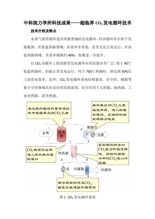
中科院力学所科技成果——超临界CO2发电循环技术技术介绍及特点
水蒸气朗肯循环是应用最普遍的发电循环,但该循环存在两个发展瓶颈,在低温热源领域,其效率非常低,甚至无法正常运行;在高温热源领域,其效率极限约40%,很难进一步提升。
以CO2为循环工质的新型发电循环应用范围非常广泛,用于90℃低温热源时,仍能正常发电运行,用于700℃热源时,即达到50%以上的发电效率。
此外,CO2发电循环系统结构紧凑,在空间、舰船等狭小空间领域具有良好的发展前景,还可应用于太阳能、地热能、工业余热能、甚至核能。
图1CO2发电循环系统
CO2作为一种自然工质,广泛存在于自然界和工业过程中,无毒、阻燃,环境友好,易于提纯,成本低廉,是一种极具发展潜力的循环工质。
应用领域
CO2的低沸点特性决定了它可广泛应用于低品位热能发电领域,包括工业余热、地热能、低温太阳热能等。
在低温热能发电领域,在效率方面远高于以水蒸气为循环介质的朗肯循环,在工质环保特性方面优于有机工质。
CO2热稳定性较强,因此与有机工质相比,仍可应用于高温热能发电领域,如高温太阳热能、生物质能、核能、化石能源等,其发电效率远高于以水蒸气为循环介质的朗肯循环。
综上,CO2发电循环是一个具有普适性的技术,其应用范围非常广泛,可大幅提升能源利用率。
技术成熟度及应用案例
中科院力学所已经建成kW级CO2跨临界发电循环实验样机,最高发电1.7kW。
图2CO2发电系统样机。
超临界二氧化碳循环

超临界二氧化碳循环
超临界二氧化碳循环是一种新兴的能源技术,它利用超临界二氧化碳作为工质,在高温高压下进行循环,从而实现能源的转换和利用。
超临界二氧化碳循环具有很多优点,比如,它可以实现高效率的能源转换,同时还可以减少环境污染和温室气体的排放。
此外,它还具有较高的安全性和可靠性,能够适应各种不同的能源供应和需求。
在超临界二氧化碳循环中,二氧化碳被加热并压缩到临界点以上的状态,从而形成超临界流体。
然后,这个超临界流体被输送到蒸汽涡轮机中,通过扩张和自然冷却来产生电力。
最后,冷却的超临界流体被再次压缩、加热和输送回循环系统中,从而实现循环。
超临界二氧化碳循环在能源领域具有广泛的应用前景,尤其是在可再生能源领域。
它可以与太阳能、风能、地热能等新能源相结合,从而实现更加高效、环保和可持续的能源利用。
- 1 -。
超临界朗肯循环
超临界朗肯循环超临界朗肯循环是一种高效的汽轮机循环过程,通过在超临界状态下运行,可以提高能量转化效率。
本文将对超临界朗肯循环的原理、特点和应用进行详细介绍。
一、超临界朗肯循环的原理超临界朗肯循环是一种改进的朗肯循环,其原理是利用超临界工质的特性来提高能量转化效率。
在传统的朗肯循环中,蒸汽在高压蒸汽发生器中被加热,然后进入汽轮机进行膨胀,最后被排出。
而在超临界朗肯循环中,蒸汽在高压蒸汽发生器中被加热至超临界状态,然后进入汽轮机进行膨胀,最后被排出。
超临界工质是指在临界点以上的温度和压力下存在的物质。
与常规蒸汽相比,超临界工质具有更高的温度和压力,能够提供更高的能量转化效率。
此外,超临界工质的密度较大,具有较高的传热性能,可以更充分地利用热能。
1. 高效性:超临界朗肯循环能够提高能量转化效率,使得能源利用更加高效。
相比传统的朗肯循环,超临界朗肯循环的效率可以提高10%以上。
2. 灵活性:超临界朗肯循环适用于多种工质,包括水、二氧化碳等。
这种灵活性使得超临界朗肯循环可以应用于不同的能源系统中。
3. 环保性:超临界朗肯循环能够减少二氧化碳等温室气体的排放,对环境更加友好。
此外,超临界朗肯循环还可以利用工业废热等低品质能源,提高能源利用效率。
4. 技术挑战:超临界朗肯循环的应用还面临一些技术挑战,包括高温高压下的材料应力、循环稳定性等问题。
解决这些问题将有助于推动超临界朗肯循环的进一步应用。
三、超临界朗肯循环的应用超临界朗肯循环已经在一些领域得到了应用,包括发电、工业生产等。
其中,发电是超临界朗肯循环的主要应用领域之一。
在发电领域,超临界朗肯循环可以应用于燃煤发电、核能发电等系统中。
通过利用超临界工质的高温高压特性,可以提高发电效率,减少能源消耗。
此外,超临界朗肯循环还可以利用工业废热等低品质能源,提高能源利用效率。
除了发电领域,超临界朗肯循环还可以应用于工业生产中的热能回收等方面。
通过利用废热等低品质能源,可以提高能源利用效率,减少能源浪费。
- 1、下载文档前请自行甄别文档内容的完整性,平台不提供额外的编辑、内容补充、找答案等附加服务。
- 2、"仅部分预览"的文档,不可在线预览部分如存在完整性等问题,可反馈申请退款(可完整预览的文档不适用该条件!)。
- 3、如文档侵犯您的权益,请联系客服反馈,我们会尽快为您处理(人工客服工作时间:9:00-18:30)。
Solar energy powered Rankine cycle using supercritical CO 2H.Yamaguchi a ,X.R.Zhanga,*,K.Fujima b ,M.Enomoto c ,N.Sawadada Department of Mechanical Engineering,Doshisha University,Kyoto 630-0321,Japan bMayekawa MFG.Co.,Ltd.,2000Tatsuzawa Moriya-city,Ibaraki-Pref.,302-0118,JapancShowa Denko K.K.,1-480,Inuzuka,Oyama-city,Tochigi 323-8679,JapandShowa Tansan Co.,Ltd.,7-1,Ogimachi,Kawasaki-Ku,Kawasaki-city,Kanagawa 210-0867,JapanReceived 14November 2005;accepted 28February 2006Available online 18April 2006AbstractA solar energy powered Rankine cycle using supercritical CO 2for combined production of electricity and thermal energy is proposed.The proposed system consists of evacuated solar collectors,power generating turbine,high-temperature heat recovery system,low-tem-perature heat recovery system,and feed pump.The system utilizes evacuated solar collectors to convert CO 2into high-temperature supercritical state,used to drive a turbine and thereby produce mechanical energy and hence electricity.The system also recovers heat (high-temperature heat and low-temperature heat),which could be used for refrigeration,air conditioning,hot water supply,etc.in domestic or commercial buildings.An experimental prototype has been designed and constructed.The prototype system has been tested under typical summer conditions in Kyoto,Japan;It was found that CO 2is efficiently converted into high-temperature supercritical state,of while electricity and hot water can be generated.The experimental results show that the solar energy powered Rankine cycle using CO 2works stably in a trans-critical region.The estimated power generation efficiency is 0.25and heat recovery efficiency is 0.65.This study shows the potential of the application of the solar-powered Rankine cycle using supercritical CO 2.Ó2006Elsevier Ltd.All rights reserved.Keywords:Solar energy;Supercritical CO 2;Rankine cycle;Power generation;Heat collection1.IntroductionThe expanding population and the energy crisis have brought serious problems to the world environment and sustainable development.The applications of renewable energies (e.g.solar and wind power)to electricity genera-tion and heat collection/refrigeration become more and more important,and has received considerable attention.During the last two decades a number of researchers have worked on developing new combined power/heat or power/refrigeration thermodynamic cycles or improving existing ones.Various systems have been suggested and developed.For example,high-temperature solar thermal technologies (including single axis and two axis tracking technologies)have been studied by a number of researchgroups [1–3].Single axis tracking systems are comprised of technologies in which relatively long and narrow reflec-tors track the sun around a single axis to keep the sun’s image in focus on a linear absorber or receiver [4,5].Two axis tracking technologies developed include paraboloidal dishes,single tower-central generation,and distributed tower systems [6–8].In addition,in recent years,low-tem-perature technologies have also been developed and the processes are more efficient than in previous systems.Ther-modynamic cycles for combined power and heat system have a great potential to become competitive with fossil fuels (especially natural gas)based power systems [9–12].The potential exists for meeting this goal by reducing the cost and improving the thermodynamic performance of power cycles by hybridization and combined cycle approaches and by employing new and innovative ideas in thermodynamic cycles.For example,Kalina [13]pro-posed the use of ammonia/water mixture as a working fluid1359-4311/$-see front matter Ó2006Elsevier Ltd.All rights reserved.doi:10.1016/j.applthermaleng.2006.02.029*Corresponding author.E-mail address:******************.ac.jp (X.R.Zhang)./locate/apthermengApplied Thermal Engineering 26(2006)2345–2354to improve thermal power cycles.Goswami[14,15]pro-posed a new thermodynamic cycle,which is an ammonia-based combined power/refrigeration cycle.From the viewpoint of protecting the ozone layer and preventing global warming,there is now strong demand for technology based on ecologically safe‘natural’working fluids,i.e.fluids like water,air,noble gases,hydrocarbons, ammonia and carbon dioxide.Table1compares the char-acteristics and properties of various workingfluids.The ozone depletion potential(ODP)is the ratio of the impact on ozone of a chemical compared to the impact of a similar mass of CFC-11.The global warming potential(GWP)is the ratio of the warming caused by a substance to the warming caused by a similar mass of carbon dioxide.From the table,it can be seen that carbon dioxide(CO2,R-744)is a non-flammable and non-toxicfluid and friendly to envi-ronment.In addition,CO2vapor pressure is much higher and its volumetric refrigeration capacity(22,545kJ/m3at 0°C)is3–10times higher than CFC,HCFC,HFC and HCfluids.Thus,the system volume would be smaller and the workingfluid charge would be lower with CO2.The CO2thermodynamic and transport properties seem to be favorable in terms of heat transfer and pressure drop, compared to other typical workingfluids[16].It can also be seen that the critical pressure and temperature of CO2are 7.38MPa(73.8bar)and31.1°C,respectively.This critical temperature is much lower than those of other workingflu-ids.Therefore,the objective of this paper is to propose a thermodynamic cycle–a solar energy powered Rankine cycle using a natural workingfluid–carbon dioxide,in which CO2can be heated in highly efficient evacuated solar collector,and solar energy can be converted into electricity and the remainder is available for heat collection and other uses.This system is of interest for clean power and heat col-lection achieved from renewable energy and natural work-ingfluid.2.Solar-powered Rankine cycle utilizing supercritical CO2The basic diagram of the proposed solar-powered Ran-kine cycle for simultaneous electricity generation and heat collection is shown in Fig.1.It consists of a solar collectorNomenclaturea1amount of petroleum consumed to produce 1kW h of electric energy,(kW h)À1a2amount of CO2emission if1kW h of electric energy is produced by petroleumfired powerplant,kg/kW hh1CO2enthalpy value at the collector outlet,J/k h2CO2enthalpy value at the turbine outlet,J/kg h3CO2enthalpy value at the outlet of the heat exchanger2,J/kgh4CO2enthalpy value at the pump outlet,J/kgm c CO2massflow rate,kg/sM e reduced CO2emission per year,kgM p saved petroleum per year,l Q in heat quantity absorbed into CO2in the collec-tor,Eq.(4),WQ out heat recovery of the Rankine cycle,Eq.(5),W t o operating time of the prototype per day,hW power power generation of the Rankine cycle,Eq.(3), WW pump power consumption of the CO2feed pump,Eq.(6),WGreek symbolsg power power generation efficiency,Eq.(1)g heat heat recovery efficiency,Eq.(2)g gen generator efficiencyTable1Characteristics of some workingfluidsR-12R-22R-134a R-407C R-410A R-717R-290R-744 ODP/GWP1/85000.05/17000/13000/16000/19000/00/30/1 Flammability/toxicity N/N N/N N/N N/N N/N Y/Y Y/N N/N Molecular mass(kg/kmol)120.986.510286.272.61744.144 Critical pressure(MPa) 4.11 4.97 4.07 4.64 4.7911.42 4.257.38 Critical temperature(°C)11296101.186.170.213396.731.1 Reduced pressure a0.070.10.070.110.160.040.110.47 Reduced temperature b0.710.740.730.760.790.670.740.9 Refrigeration capacity c(kJ/m3)273443562868402967634382390722,545 The data in the table come from Ref.[16].R-12:dichlorodifluoromethane;R-22:chlorodifluoromethane;R-134a:tetrafluoroethane;R-407C:ternary mixture of difluoromethane/pentafluoro-ethane/tetrafluoroethane(23/25/52,%);R-410A:binary mixture of difluoromethane/pentafluoroethane(50/50,%);R-717:ammonia;R-290:propane; R-744:carbon dioxide.a Ratio of saturation pressure at0°C to critical pressure.b Ratio of273.15K(0°C)to critical temperature in Kelvin.c Volumetric refrigeration capacity at0°C.2346H.Yamaguchi et al./Applied Thermal Engineering26(2006)2345–2354array,power generating turbine,high-temperature heat recovery system,low-temperature heat recovery system and feed pump.Solar collector is used to heat CO 2contained in heating channels and increase CO 2temperature.This heat transfer process results in the trans-critical cycle,i.e.with sub-critical low-side and supercritical high-side pressure.The heating in the solar collector makes supercritical CO 2high-temperature state (Fig.1,state 1),reaching a level suitable for simultaneous use of turbines and heat recovery systems.The supercritical CO 2drives the engine of the Rankine system,and hence the connected electrical gener-ator.Power output can be available from the turbine gen-erator.The lower pressure CO 2,which is expelled from turbine,is cooled in the high-temperature heat recovery system.At the outlet of turbine,CO 2still has a higher tem-perature (Fig.1,state 2),which can be used to provide heat source for absorption refrigerating machine,boiling water or other uses.The process can be achieved in the high-tem-perature heat recovery system.The high-temperature heat recovery system is actually a heat exchanger.After leaving the high-temperature heat recovery system,CO 2enters the low-temperature heat recovery system in which CO 2can be further cooled and heat can be further recovered.For example,the cold water can be heated and used for bath,air conditioning and so on in a building.In the low-temper-ature heat recovery system,CO 2is cooled to a liquid state (Fig.1,state 3)and after that,it is pumped by the feed pump,back into the higher pressure condition (Fig.1,state 4),and the cycle recommences.Based on the concept shown in Fig.1,the operation of the hybrid combined cycle using CO 2can be demonstrated as shown in Fig.2,in which the processes of the cycle are shown in the P –h and T –s diagrams qualitatively.Point ‘‘CP’’represents the critical point (the critical pressure7.38MPa and temperature 31.1°C).Because of the high temperature in the solar collector,this CO 2-based Rankine cycle would have to operate in the trans-critical cycle most of the time,i.e.with heat absorption above the critical tem-perature and supercritical high-side pressure.However,the low-side conditions would remain sub-critical.In Fig.2,each point corresponds to the state 1–4of Fig.1.The point ‘‘1’’represents the high-temperature supercritical state of carbon dioxide at the solar collector outlet,4–1represents the heating process of carbon dioxide in the solar collector and 2–3represents the heat recovery process.In the cycle,1–2represents the power output (a turbine process)and 3–4is a pumping process.As shown in this figure,CO 2works basically in the supercritical region in the heating process 4–1occurring in the solar collector.In the process 2–3,CO 2is changed from gas to liquid state.So such design has an important characteristic;the CO 2at state 3,i.e.at the outlet of the low-temperature heat recovery system,needs to be designed well into liquid state to acquire a good pumping ability and to reach a high pressure at state 4.In the operating ranges of the CO 2-based Rankine cycle sys-tem (operating in a trans-critical mode),the pump work,the power output and the total cycle efficiency are affected by the pressure level.The CO 2-based Rankine cycle has two energy outputs,one is the power generation and another is the heat recov-ery.So the following two efficiencies are defined to describe the cycle performance,power generation efficiency g power and heat recovery efficiency g heat :g power ¼W power Q in ð1Þg heat¼Q outQ inð2Þwhere W power is the power generation obtained from the turbine,Q in is the heat quantity absorbed into CO 2in the solar collector,and Q out is the heat quantity recovered from the CO 2-based cycle.The cycle performance parame-ters can be calculated as:W power ¼g gen m c ðh 1Àh 2Þð3ÞQ in ¼m c ðh 1Àh 4Þð4ÞQ out ¼m c ðh 2Àh 3Þð5ÞW pump ¼m c ðh 4Àh 3Þð6Þwhere m c is the mass flow rate of CO 2in the cycle loop;g gen is the turbine efficiency.3.Experimental set-upBased on the concept proposed in Fig.1,a prototype of the CO 2-based Rankine cycle powered by solar energy was designed,constructed,and tested.This prototype was installed on the roof of Energy Conversion Research Cen-ter in Doshisha University,shown in Fig.3.A schematic diagram of the experimental prototype is shown in Fig.4.The prototype is mainly comprised of evacuatedsolarFig.1.A novel solar energy powered Rankine cycle using supercritical CO 2for combined power generation and heat recovery.H.Yamaguchi et al./Applied Thermal Engineering 26(2006)2345–23542347collector arrays,a throttling valve,heat exchangers1and2 (CO2/water heat exchanger),liquid CO2feed pump,cool-ing tower and measurement and data acquisition system.A supercritical CO2actually has physical properties somewhere between those of a liquid and a gas.So it is dif-ficult to decide whether a turbine of a gas or a liquid type should be used for the Rankine cycle using supercritical CO2.In other words,to date there is no turbine available for supercritical CO2.Therefore,in this prototype,a throt-tling valve was used,instead of a turbine,in order to study the cycle performance.The throttling valve can provide various extents of opening for the cycle loop in order to simulate pressure drop occurring in realistic turbine condi-tion and consequently a thermodynamic cycle can be achieved.Clearly the CO2temperature and its thermody-namic and transport properties and states at the valve out-let are different from those of the true turbine condition,which will affect the heat recovery aspects of the cycle to a certain extent.No electricity power is produced in this prototype,but the cycle performance for the power/heat production can be derived based on thermodynamic analy-sis.In order to estimate the cycle performances,in the pres-ent study,a value of the generator efficiency g gen=0.92is used to calculate the produced electric power.The solar collector is the heart of the solar-powered Rankine system.Its characteristics play an important role in successful operation.To make sure the system is effi-cient,a solar collector with good heat collecting character-istics is required.Therefore,to effectively heat CO2to a higher-temperature supercritical state in the prototype, all-glass evacuated solar collectors with a U-tube heat removal system are used,shown in Fig.3(a)and(b).These collectors consist of a glass envelope(38mm in diameter) over an inner glass tube(27mm in diameter)coated with2348H.Yamaguchi et al./Applied Thermal Engineering26(2006)2345–2354a selective solar absorber coating.This coating with a high solar absorbance 0.927and a low emissivity 0.193is applied on the vacuum side of the inner glass tube.The absorbed heat is conducted through the inner glass tube wall and then removed by heat removal fluid in a metal U-tube (3.6m in length and 0.005m in internal diameter)inserted in the inner tube with an aluminum fin (1.7m in length)connecting the outlet arm of the U-tube to the inner glass tube.In this prototype,evacuated solar collector of 29.0m 2is used (efficient area of 9.6m 2).The collector used is commercial product provided by Showa Denko K.K.,designed to have a maximum allowable work pressure of 12MPa and have a maximum working temperature of 250°C.A piston pump is used for feeding liquid CO 2in the pro-totype.This canned motor feed pump can provide a max-imum operating pressure of 12MPa and flow rate of 0.03kg/s,respectively.A Coriolis effect mass flow meter is used in the cycle to monitor and record the mass flow of liquid CO 2,which also has a maximum permissible oper-ating pressure of 12MPa.The flow meter is installed in the downstream side of the CO 2feed pump,as shown in Fig.4.It provides a measurement range of 0.09–1.0kg/min with an accuracy of ±0.1%.Five T-type thermocouples and five pressure transmit-ters were mounted at different positions in the CO 2flow to measure its temperatures and pressures,with an accu-racy of ±0.1°C for temperature measurements and ±0.2%for pressure measurements.Measured quantities include the following:CO 2temperatures and pressures at the collector outlet;at the outlet of the throttling valve;at the outlet of the heat exchanger 1;at the outlet oftheFig.3.(a)A prototype photograph of the CO 2-based solar-powered Rankine cycle.(b)A sketch of the evacuated solar collector used in the Rankine cycle.H.Yamaguchi et al./Applied Thermal Engineering 26(2006)2345–23542349heat exchanger 2;at the outlet of the CO 2feed pump.The measuring points of these sensors are also shown in Fig.4.The heat recovery components are intended to collect heat from the CO 2cycle,and cool CO 2to low enough into liquid state to form a complete Rankine cycle.There are simultaneous high-temperature and low-temperature heat recovery systems installed in the prototype in order to respectively achieve high-temperature and low-temperature heat recovery.In the present study,higher-temperature water and lower-temperature water are respectively sup-plied to the heat exchangers 1and 2to simulate the high-and low-temperature heat recoveries,as shown in Fig.4.So the heat recovery subsystems used in the prototype are comprised of heat exchangers 1and 2(CO 2/water heat exchanger),cooling tower,heat exchanger 3(water/water heat exchanger),and water pumps,etc.(shown in Fig.4).A mechanical-draft water cooling tower (with a cooling capacity of 22kW)is used as a heat sink,dissipating heat recovered from the Rankine cycle to the ambient.In order to achieve a good heat exchange between CO 2and water,shell and tube design is used for the heat exchangers 1and 2,with tube side of CO 2and shell side of water.The temperature of water used to recover heat in the high-tem-perature heat recovery system is determined by CO 2tem-perature and cooling capacity of the cooling tower.Hence during the experiment the water flow rate and cool-ing capacity are adjusted to provide a suitable water tem-perature for the heat recovery.There are four platinum resistor temperature sensors mounted to measure inlet and outlet water temperatures of the heat exchangers,with an accuracy of ±0.15+0.0002j t j °C.Water flow rates of the heat exchangers 1and 2are measured by two water flow meters mounted at the outlets of the heat exchangers,with an accuracy of ±0.5%.It should be mentioned that if the turbine work is small or the need for electricity is small,the CO 2temperatures can be lowered to the level of state 2.Thus the collector design can be considerably simplified and the system becomes fundamentally a solar-to-thermal energy system.A meteorological measurement system was also installed,which is mainly comprised of sun radiation sensor,ane-mometer,and air temperature gauge and so on.In this paper,only measured solar radiation and atmospheric temperature are presented,and accuracies of the sun radia-tion sensor and the air temperature gauge are respectively ±0.3%and ±0.15+0.002j t j °C.In addition,a measurement and data acquisition system is used in the prototype.The system can achieve real-time data measurement,acquisition,processing,and share.The output signals of the experimen-tal data can be automatically transported through the com-puterized data acquisition system and recorded as functions of time.During a typical experiment,water pumps are first turned on and the water flow rates are adjusted.Then the CO 2feed pump is switched on and the opening of the valve is adjusted to the expected extent.The CO 2pump is turned offafter the test is finished.This is done only after adjusting the valve to a state of full open.Finally the water pumps are turned off.During the experiment,the two major error sources are:(1)temperature,pressure and flowrateFig.4.Schematic diagram of the prototype machine system.2350H.Yamaguchi et al./Applied Thermal Engineering 26(2006)2345–2354measurement accuracy;(2)error resulting from data logging and reading by the computer.The error of data logging and reading include as follows:±0.1%for CO2 temperature;±0.3%for CO2pressure;±0.3%for CO2 massflow rate;±0.2%for water temperature;±0.3% for waterflow rate;±0.3%for solar radiation;±0.2%for atmospheric temperature.A detailed error analysis indi-cates that the maximum uncertainty in the performance parameters is less than±3.0%.Therefore,these errors are acceptable for the present study.Thermal insulation coating applied on all the carbon dioxide and water loops to reduce heat losses from the piping.4.Experimental results and discussionThe prototype performance was tested in summer condi-tions(July2004)in the city of Kyoto of Japan.As thefirst step of fundamental understanding of the cycle perfor-mance,the charged CO2amount was decided only to achieve a trans-critical Rankine cycle,not declared opti-mum when the maximum efficiency was achieved.In addi-tion,the CO2temperature and pressure at the outlet of the solar collector are important factors in achieving a good heat recovery and power generation.So efforts were made to measure CO2temperatures and pressures etc.to study the cycle feasibility.There seems an obvious influence of the total amount of CO2charged on the system operation and performance. The tests of system performance werefirst carried out under a charge amount of5.0kg,under which CO2flow rate wasdetected to be zero in the prototype cycle.At the CO2 charge of5.0kg and the atmospheric temperature of about 30°C,the system pressure(under no operation conditions) is about4.8MPa.In order to make CO2to a liquid state, CO2has to be cooled below12°C at the pump suction(state 3shown in Fig.3).This is very difficult to achieve in the pro-totype.However,when the charge amount is increased to 5.5kg,the system pressure is about6.0MPa under no oper-ation conditions.It became easy for CO2to be cooled into liquid state(about22°C,state3).So there is a lower limit of CO2inventory in the prototype loop to complete a Rankine cycle.Conversely,there is also an upper limit for the loop pressure to achieve a safe operation.The total amount of CO2charged needs to be optimized for the maximum efficiency and safe operation in the future.All the perfor-mance tests presented in this paper were performed under a total amount5.5kg of CO2charged.Fig.5(a)shows solar radiation and atmosphere temper-ature measured with a function of time.The solar radiation increases with time from9:00until it reaches a maximum value of around0.90kW/m2at12:00.Then,the solar radi-ation begins to decrease until5:20at0.25kW/m2.The inlet and outlet water temperatures of the heat exchangers1and 2are shown in Fig.5(b),in which the waterflow rates are also included.It can be seen that during most of the time of the test,the inlet water temperature andflow rate for the heat exchanger2are respectively maintained at12.0°C and0.0194kg/s.The waterflow rate of the heat exchanger 1is set at0.0167kg/s.The water temperatures of the heat exchanger1depend on the CO2temperatures and the cool-ing capacity of the cooling tower.The water temperature of the heat exchanger2is also determined by the CO2temper-atures.Therefore,variations of the water temperatures are similar to those of the CO2temperatures at the collector outlet and valve outlet,which is shown in Fig.6(a). Fig.6(a)shows the measured CO2temperatures,in which the CO2flow rate is also included.During the test hours of9:00to11:00,the throttling valve was in a full open state.At the11:00,the valve was adjusted to a state of one-third open.As shown in Fig.6,after the system starts, the CO2flow rate rises up gradually to about0.0133kg/s. After11:00,because the valve is two-thirds closed,the CO2flow rate is reduced to about0.0067kg/s.After starting the prototype,the CO2temperatures increase with elapsed time until11:00.At11:00,the CO2 temperature at the collector outlet reaches up to about 165°C.At the same time,the water temperatures of the heat recovery systems also increase with time(shown in Fig.5(b)),which is due to the increase of the CO2temper-atures.After11:00,the temperatures of carbon dioxide and water decrease(shown in Fig.5(b)).The CO2temperaturesH.Yamaguchi et al./Applied Thermal Engineering26(2006)2345–23542351in the collector depend on the CO2flow rate m c and the heat input Q in.The CO2flow rate is reduced by two-thirds closing the valve and the CO2fluid stays longer in the col-lector.But the heat convection coefficient and the heat quantity extracted from the absorber contained in the vac-uum tubes are largely decreased.So the CO2temperatures did not increase with decreasingflow rate.It is shown in Fig.6(a)that the quick drop of the system temperatures end almost at11:30.During the hours of11:30to14:00, the system temperatures tend to be stable not only in the CO2temperature,but also in the water temperatures (shown in Fig.5(b)).However,it is seen that after14:00, there is a gradual decrease in the CO2and water tempera-tures.The temperature decreases are caused by a natural decrease in the solar radiation and atmospheric tempera-ture(shown in Fig.5(a)).During the relatively stable work-ing of the cycle(from11:30to17:20),about25°C temperature difference exists between the inlet and outlet of the valve.In addition,with aflow rate of0.0067–0.0133kg/s,the tube diameter of the CO2cycle loop is 0.01m.Thermal losses from the small lines such as these will be significant.Therefore a good thermal insulation is necessary for the CO2cycle loop to reduce thermal loss.Fig.6(b)shows the CO2pressures measured during the test hours.It can be seen that before11:00,because the valve is in the state of full open,the CO2pressures of the various monitoring points in the prototype are almost the same.But after11:00(the valve is two-thirds closed),the supercritical high-pressure side and sub-critical low-pressure side of the CO2-based Rankine cycle can be obviously observed in thisfigure.The high pressure reaches up to8.7MPa and low pressure about6.2MPa.These results show that during the most time of the test,the CO2-based prototype works in a trans-critical Rankine cycle.Furthermore,the energy outputs from the CO2-based Rankine cycle(the power generation W power and the heat recovery Q out)and the heat quantity absorbed into CO2 in the collector Q in are shown in Fig.6(c).The temperature and pressure values are obtained experimentally,also including CO2flow rate.Then enthalpy values at the differ-ent monitoring points are calculated based the measured temperature and pressure values using a Program Package for Thermophysical Properties of Fluids database version 12.1(PROPATH12.1).Based on Eqs.(4)–(7),the power generation and heat recovery are obtained.From Fig.6(c),it is seen that variation of Q in with time is similar to that of solar radiation measured with the time to a certain extent.The time-averaged Q in is estimated at 1610.2W.The power generation W power and heat recovery Q out are found to be relatively stable throughout the test hours.The time-averaged W power and Q out are estimated at401.1W and1050.4W,respectively.The total output from the cycle is about1451.5W.The power generation2352H.Yamaguchi et al./Applied Thermal Engineering26(2006)2345–2354of401.1W was obtained based on some assumptions described above and a true turbine condition is needed fur-ther to investigate the Rankine cycle outputs.It should be mentioned here that how much the heat quantity recovered Q out which can be used as useful heat depends on real user demand.In addition,in the real turbine condition Q out may decrease because of a larger temperature drop between states1and2,compared to that in the valve condition.The power generation efficiency g power and heat recovery efficiency g heat of the Rankine cycle are shown in Fig.6(d). In thefigure,the time-averaged g power is found to be0.25 and g heat is0.65.A previous theoretical study[17]was con-ducted in the turbine condition,in which an annual aver-aged power generation efficiency and heat recovery efficiency are0.22and0.68,respectively.A comparison between the experimental data and the theoretical analysis shows that the theoretical predictions are close to the mea-surement values.The difference between the experimental data and numerical predictions may be due to the assump-tions and simplifications made in the steady state analysis. The measured is0.25,higher than the calculated value of 0.22.The reason given to this phenomena may be that the averaged CO2flow rate in the experiment is a little higher than the value used in the simulation,and this value of0.25was obtained under the summer.But to a certain extent,the agreement is found and therefore the theoretical work can be verified by the experimental data.In addition, an annual experiment work[18]shows the annually aver-aged g power is found to be0.22,which is close to the value obtained in the present study.It is noted that the power consumption of the CO2feed pump is not considered in the efficiencies above,because the pump used is originally designed for water and the con-sumption is large,about220.0W.If the power consump-tion is considered,g power would drop to about0.11, which represents the thermal efficiency of the Rankine cycle,and g heat would drop to about0.52.Therefore a feed pump with higher efficiency or solar energy powered pump will be considered to reduce the power consumption.It is also seen from Fig.6(d)that g heat is much higher than g power,and therefore,to a certain extent,the benefit obtained from the CO2-based cycle also largely stems from the reasonable utilizations of the recovered heat quantity. It should also be mentioned that the turbine may have very small blades andfluid leakage past the blades is likely to be significant.So the expansion efficiency may have low to moderate efficiencies characteristic of small generators, inverters,and motors.An analysis of energy conversion was conducted based on the US Electric Power Annual.If the present prototype is used instead of a petroleum-fired power plant,the saved petroleum M p and the reduced CO2emission M e per year can be simply estimated as:M p¼365t o a1ðW powerþQ outÀW pumpÞð7ÞM e¼365t o a2ðW powerþQ outÀW pumpÞð8Þwhere t o is operating time per day,a1is the amount of petroleum consumed to produce1kW h of electrical en-ergy and a2is the amount of CO2emission if1kW h of electrical energy is produced by a petroleumfired power plant.In this paper,t o=7.0h,a1=0.266l/kW h,and a2=0.894kg/kW h are used.In the simple analysis,W power and Q out are assumed not to be changed with seasons during a year.The planed pro-totype system is about10times larger than the present one, in which the efficient collector area will be increased to 100m2in the near future.Table2shows the economic esti-mation results.The petroleum of M p=8.5kl can be saved per year,and furthermore,the CO2emission of about M e=28237.0kg can be reduced per year.Here it is assumed that10,000set of machine systems were manufac-tured per year and the capital investment for users can be paid back during5years.So a cost of US$0.047per kW h for the total energy output and US$0.176per kW h for electric energy are obtained.This does not include any local environmental improvement which might be val-ued.The cost is expected to drop further if the system is available in large production or is optimized and the effi-ciency of conversion is higher,or simple and cheaper evac-uated tube collectors are designed for higher collecting efficiency.It should be mentioned here that the estimations made in Table2are based on some rough assumptions and the results vary with specific cases.In general,the solar-powered Rankine cycle using CO2 can provide a cogeneration of electricity and heat with rea-sonable thermodynamic cycle efficiencies,effectively reduce CO2emission and avoid the toxicity orflammability risks of ammonia and hydrocarbons.But a true turbine condi-tion is actually needed to further investigate the cycle per-formance.The thermal energy recovered from the cycle can efficiently supply a facility with domestic hot water,spacing heating,or heat to drive a chiller,a desiccant dryer,or some other thermal load.Therefore,the CO2-based Ran-kine cycle powered by solar energy is suited for the energy loads of commercial facilities,hotels,schools,hospitals, office buildings,multifamily dwellings,and other facilities that can benefit from an independent source of power and heat,clean and reliable power on site at the point of use.5.ConclusionsA solar energy powered Rankine cycle using supercriti-cal CO2is proposed.The cycle is a combination of using renewable energy(solar energy)and natural workingfluid Table2Economics of solar energy powered Rankine cycle using CO2Estimation resultsM p(saved petroleum)8.5kl/yearM e(reduced CO2emission)28,237.0kg/yearCost(for total energy)US$0.047/kW hCost(for electric energy)US$0.176/kW hH.Yamaguchi et al./Applied Thermal Engineering26(2006)2345–23542353。