JWM-A说明书(中文)
JWM说明书

前言SMART LOCK SYSTEM是基于Mifare卡技术的感应卡门锁管理系统和西门子4442卡技术的门锁管理系统,主要应用于宾馆、酒店、别墅、会所、度假村、酒店式公寓等。
是针对于旅馆业的客房、办公室、门禁、通道等门锁系统的完全解决方案。
对于本系统,每个用户均有一个独立用户序列号,用户在安装本系统前,请确认您已经拥有厂家提供给您的用户序列号;用户必须对自己的序列号的保密性负责,并授权专人对其进行保管,不能使序列号泄漏或扩散。
无论何种原因,用户或保管人泄露了酒店唯一的序列号,而造成自身或第三方的损失全部由泄漏方独自承担;如果对厂家造成直接或间接的经济损失,泄漏方必须赔偿由此而带给厂家的所有损失。
本说明书各部分主要内容说明如下:第一部分:门锁软件系统基本使用功能说明本章主要介绍了门锁软件的安装、设置等基本操作,客户只需要按照本章的内容和顺序操作,就可以快速启用本门锁系统。
第二部分:门锁系统的管理功能介绍本章主要讲解本门锁系统各种管理功能,以及其详细的操作说明;客户在出现问题,需要了解详细操作办法时,直接在本章节查看对应的相关内容即可。
第三部分:附录部分主要对SQL Server 2000的安装和使用进行说明;同时讲解了通过SQL Server备份和还原数据库数据的操作。
SMART LOCK SYSYTEM单机版采用Microsoft Access作为数据库;网络版采用SQL Server数据库,数据库名为:Lock_Mifare如果您在使用我公司产品过程中需要我们帮助,可通过以下方式与我们联系:深圳德智丰电子有限公司2008年01月目录第一部分:MIFARE CARD LOCK门锁管理系统基本使用说明 (1)1 使用前的准备 (1)2 安装MIFARE CARD LOCK (2)3 连接发卡机 (3)4 第一次运行MIFARE CARD LOCK门锁管理软件 (4)5 酒店客房基本信息设置 (6)5.1 生成客房区域信息 (6)5.2 定义客房类型 (7)5.3 生成客房门锁 (8)5.4 发行初始化门锁的各类功能设置卡 (9)5.4.1 发行系统卡 (9)5.4.2 发行设置卡 (11)5.4.3 发行参数卡 (11)5.5 初始化客房门锁 (12)5.6 发行服务员用的开门卡 (13)5.6.1发行总控卡 (13)5.6.1发行领班卡 (14)5.6.2发行楼层卡 (14)5.6.3发行清洁卡 (15)5.7 发行宾客卡 (15)5.7.1 散客发卡 (15)5.7.2 团体发卡 (17)5.7.3 通过房态表进行发卡 (18)第二部分:MIFARE CARD LOCK门锁管理系统其他管理功能说明 (19)1 基础数据 (19)1.1 基础数据维护 (19)1.2 公共通道管理 (20)2 门锁管理 (21)3 门锁层次管理 (21)4 设置职员(办公)用房 (22)5 系统维护 (23)5.1 系统参数 (23)5.2 数据库维护 (25)5.3 定义角色权限 (25)5.4 用户管理 (27)5.5 设置显示语言 (29)5.6 更改当前用户登录密码 (29)6 发卡管理 (29)6.1 发行设置类卡 (29)6.1.1 发行中止卡、会议卡、应急卡 (29)6.1.2 发行注销卡 (30)6.1.3 发行数据卡 (30)6.2 发行职员类卡 (31)6.2.1 发行职员卡 (31)6.2.2 发行电梯卡 (32)6.2.3 发行备用卡 (32)6.3 挂失卡 (33)6.3.1 挂失系统卡 (33)6.3.2 挂失设置卡 (33)6.3.3 挂失参数卡、会议卡、中止卡 (34)6.3.4 挂失总控卡、时钟卡、注销卡、应急卡 (34)6.3.5 挂失领班卡、楼层卡、清洁卡 (34)6.3.6 挂失数据卡、职员卡、备用卡 (34)6.3.7 损毁卡的处理 (35)7 查询报表 (35)7.1 登录日志查询 (35)7.2 发卡查询 (35)7.3 门锁查询 (35)7.4 房态查询 (36)7.5 开门记录 (36)8 设置门锁 (37)8.1 设置客房门锁 (37)8.2 设置通道门锁、门禁、电梯控制器 (37)9 客房锁定/解锁 (38)10 酒店前台操作实务处理 (39)10.1 换房、续房的处理 (39)10.1.1 换房 (39)10.1.2 续房 (39)10.2 退房处理 (40)10.2.1 客人退房 (40)10.2.2 客人正常退房(非提前退房)时,但又没有交回门卡的处理 (40)10.2.3 客人提前走,但又未向酒店交回门卡的处理 (40)10.2.4 客人住宿期间丢卡的处理 (41)10.3 客房有特殊情况的处理 (41)10.3.1 客人欠费的处理 (41)10.3.2 客人住宿期间丢失财物的处理 (41)10.3.3 客人住宿期间出现特殊情况需对客房进行封锁的处理 (41)10.3.4 有效宾客卡损坏的处理 (42)10.4 中止卡的使用 (42)10.5 注销卡的使用 (42)10.6 会议卡的使用(门锁常开状态) (42)10.7 前台操作员注意事项 (42)11 客房部门锁使用指南 (42)11.1 客房部常用卡的的功能介绍 (42)11.2 客房部常用卡的使用 (43)11.3 门卡的使用注意事项 (43)11.4 门锁的使用保养 (43)11.5 发现如下情况时,服务人员应及时向相关部门报修门锁 (43)11.6 引导客人正确使用门卡 (44)11.7 客人住宿期间报失的处理 (44)12 工程部维护指导 (45)12.1 门锁设置指南 (45)12.2 工程维护人员日常工作维护 (45)12.3 熟悉门锁在门上的拆卸(图示) (45)13 系统管理员日常工作维护 (46)13.1 电脑系统优化 (46)13.2 数据备份 (46)13.3 校对时钟 (46)13.4 对前台操作员工作指导 (47)13.5 客户端的维护 (47)14 与酒店管理软件前台接待系统的接口 (47)14.1 查找门锁软件系统ID号 (47)14.2 申请并在门锁软件中输入接口授权码 (47)15 会员功能 (47)15.1 参数设置 (47)15.2 积分管理 (48)15.3 兑奖管理 (49)15.4 会员管理 (49)15.5 会员服务 (50)15.6 会员卡挂失 (50)15.7 会员卡查询 (50)15.8 会员帐务查询 (51)15.9 会员积分查询 (51)附录一 (51)1 SQL Server 2000的安装 (51)1.1 安装前说明 (51)1.2 SQL Server2000的安装步骤 (51)2 启动SQL Server服务管理器 (55)3 软件安装过程中显示“连接数据库失败”的原因及其解决办法 (56)附录二安装USB发卡机操作指南第一部分:SMART CARD LOCK门锁管理系统基本使用说明为了便于客户快速熟悉并使用本门锁系统,本章简单介绍了门锁系统的安装和基本的发卡、设置流程;用户若无其他特殊设置要求,只需要按照本章节讲述的内容及顺序按步操作,就能快速启用本系统!1 使用前的准备在开始准备安装使用本系统前,需要酒店检查以下条件是否已经准备好:1.门锁已经安装完毕,并已确定好客房号码和贴好门牌号,楼层卫生已经基本结束;2.酒店网络已经连通;前台电脑已经全部准备到位;电脑配置如下;硬件要求1)Pentium4 1.7G或同等要求以上的PC品牌机;2)至少有一个空置的9针串口(没有9针串口的,自行购买一个PCI的串口转换卡或购买一根USB口转9针串口的线,并保证其能正常通讯);3)VGA彩显(真彩色32位,分辨率能上到800*600以上);4)512MB以上内存;5)4G以上可用硬盘空间;6)有网卡,且采用TCP/IP协议,并设定了一个固定IP地址,且不能擅自更改计算机名称及IP地址。
Acom JW-1 高级顶加载权重衡器用户手册说明书

Acom Corporation would like to thank you for purchasing our model JW-1 Advanced top loading balance. We are committed to creating high quality low maintenance products and supplying our customers with diligent customer service. This manual contains information on the proper assembly and use of the scale.
Disclaimer:
This company makes no representations or warranties, either expressed or implied, with respect to the contents hereof and specifically disclaims any warranties of merchantability or fitness for any particular purpose. Any software described in this manual is sold or licensed “as is”. Should the programs prove defective following their purchase, the buyer (and not this company, its distributors, or its dealers) assumes the entire cost of all necessary servicing, repair, and any incidental or consequential damages resulting from any defect in the software. Further, this company reserves the right to revise this publication and to make changes from time to time in the contents hereof without obligation to notify any person of such revision or changes.
安沃特mpv系列调节控制阀安装与维护说明书

MODULATING CONTROL VALVESERIES MPVINSTRUCTIONS FOR THEINSTALLATION AND MAINTENANCE1. M AIN F EATURES 22. TECHNICAL FEATURES 23. INSTALLATION 34. ELECTRIC CONNECTIONS 45. WIRING 55.1 W ITHOUT MANUAL/AUTOMATIC CONTROL STATION 55.2 W ITH MANUAL/AUTOMATIC CONTROL STATION 66. AUXILIARY MICROSWITCHES 77. POTENTIOMETER/S 78. CONTROL STATION 79. CALIBRATIONS 89.1 L IMIT SWITCH89.2 P OTENTIOMETER/S99.3 E LECTRONIC CARD109.4 M AX. CAPACITY ADJUSTMENT1110. START-UP 1111. MAINTENANCE AND CHECKS 1112. REPLACEMENT 111.MAIN FEATURESThe modulating valves in the MPV [Modulating Plug Valve] series have been designedwith a modern concept and they are DVGW approved, with CE identification number.They are suitable to be used in commercial and industrial combustion systems.They are especially suitable for the proportional adjustment of non corrosive fuel gasesfrom the first, second and third family and air. The MPV valve is an adjustment devicewithout zero closing. The actuator is equipped with a single-pole bi-directional motorwith high static torque and holding torque for 3-positional control or electronicmodulation with analogic signal current [4 ÷ 20 mA] or tension [0 ÷ 10 Vdc] variationat. The adjustment of flow volume in the valve operates by a delivery adjustingcylinder with linear characteristics. The cylinder rotation changes the passage openingand the flow volume is adjusted according to a linear trend.Three different orifice sizes are available according to the operating conditions, interchangeable without removing he valve from the plant.exclusively by skilled and authorized service technicians. Non-proper installation,adjustment, modifications, use and maintenance may cause injuries to the staff ormaterial damages. It is therefore necessary to respect strictly the followinginstructions and local prescriptions for the installation of electric and gas devices.2.TECHNICAL FEATURESOperating pressure : max. 500 mbarValve group : 2Ambient temperature : from -10 to +60°CAdjusting ratio : 25:1Fittings : Rp 1, according to ISO 7-1Delivery feature : linearValve : without zero closingAvailable voltage : 230 Vac / 50 - 60 Hz115 Vac / 50 - 60 Hz24 Vac / 50 - 60 HzNominal load : 7 VAElectric protection : IP 54 according to EN60529Duty cycle : continuous 100%Cable fasteners : 2 x Pg 13.5Opening/closing times : 30 ÷ 60 seconds at 50 HzLimit - Aux. switches rating : 5 [1] A 250 VacAvailable potentiometers : 150, 1000 [standard], 2500 ohmControl signal : 4 ÷ 20 mA [only with supply voltage 24 Vac][for electronic version]: 0 ÷ 10 Vdc [only with supply voltage 24 Vac]by-passmanualadjustable Accessories :3.INSTALLATION3.1Make sure that all the operating data shown on the valve label comply with thesystem operating data.3.2When installing the valve be sure that there is sufficient clearance above thegear cover and that it can be easily accessible in order to perform the electricalconnections and the calibration of the electric limit switches.3.3Install a filter before the MPV valve.3.4Before installing the valve, make sure the piping is clean and free of everyimpurity, and it is perfectly aligned with the valve body and not subject tovibrations.3.5Remove the protection plugs installed on the valve body.3.6The sealant must be applied only on the piping outer threading and not on thevalve inner threading. Use gas suitable sealants only.3.7Comply with the gas flow direction marked by the arrows on the valve body.3.8The MPV valve installation can be carried out in every position.3.9The MPV valve can be installed in every premise included in the range of theelectric protection IP 54, except for premises with presence of acid fumes orother vapours that can etch the metal parts, in atmosphere with gas orexplosive vapour leaks.3.10For the installation of the MPV valve on the piping do not use the actuator aslever, rather use the suitable wrench.3.11Install the MPV valve without voltage.4.ELECTRIC CONNECTIONS4.1Arrange the wiring and the grounding according to the local norms in force.4.2To access the inner terminal board and for the electric connections, remove thecover loosening the 4 fastening screws.4.3Two threaded holes for cable pressers Pg 13.5 are already arranged on thebase of the electric actuator.4.4Before servicing make sure, that power supply is disconnected by means of thetwo-pole-switch [phase and neutral]; in case of non-observance, damages topeople and equipments may occur.4.5All wires must comply with local prescriptions and, in any case, their sectionmust be ranging between 1 and 1.5 mm2. Connection piping recommendedH07V-U…G1.5 mm2.4.6Wiring diagrams are reported in the attached technical bulletin and on the plateinside the cover.4.7Auxiliary microswitches are single-pole double through and voltage-free.4.8If a potentiometer is installed, its resistance value is indicated on thenameplate.4.9Make sure the supply voltage and the system frequency correspond to thoseindicated on the valve plate.4.10Low-tension signalling cable [tension lower than 48V] must be laid separatelyfrom the higher-tension conduits [tension higher than 48V]. In case they arelaid in a single channel, screened cables must be used.5.WIRINGThe wiring schemes refer to the valve in “closed” [0°] position.5.1W ITHOUT MANUAL/AUTOMATIC CONTROL STATIONT ERMINAL BOARDTerminal earthingTerminal N1 N = neutralTerminal L2 by tension the valve closesTerminal 3 by tension the valve opensTerminal 4 for manual electric operationTerminal 16 answer signal when the valve reaches the “open” positionTerminal 17 answer signal when the valve reaches the “closed” position5.2W ITH MANUAL/AUTOMATIC CONTROL STATIONTerminal earthingTerminal 1 N = neutralTerminal 2 by tension the valve closesTerminal 3 by tension the valve opensTerminal 4 for manual electric controlTerminal 16 answer signal when the valve reaches the “open” positionTerminal 17 answer signal when the valve reaches the “closed” position microswitches6.3 AuxiliaryTerminal 20 common contact from the auxiliary microswitch S3Terminal 21 normally open contact of the auxiliary microswitch S3Terminal 22 normally closed contact of the auxiliary microswitch S3Terminal 23 common contact from the auxiliary microswitch S4Terminal 24 normally open contact of the auxiliary microswitch S4Terminal 25 normally closed contact of the auxiliary microswitch S46.4 Potentiometer/s for answer signal of the position Pot. A and/or Pot. BTerminal 30 max. valueTerminal 31 cursorTerminal 32 min. valueTerminal 33 max. valueTerminal 34 cursorTerminal 35 min. value6.AUXILIARY MICROSWITCHESOn request, the valve can be equipped with 2 auxiliary microswitches that can be adjusted in any position.Microswitches are voltage-free.The contact capacity is 5 A/250 Vac with ohmic load and 1 A/250 Vac with inductive load.Contact rating is about 5 A/250 with Ohm load and about 1 A/250 with inductive load.For adjusting the cams of auxiliary microswitches, proceed as for cams of endswitches as indicated in paragraph 9.1 chapter 9 “CALIBRATIONS”.7.POTENTIOMETER/SOn request, the valve can be equipped with 1 or 2 independent potentiometers [pot. A and/or Pot. B] for the answer signal of the valve position.Resistance value of the potentiometer is indicated on the identification label.If the resistance value does not correspond to the wished one, proceed as indicated in paragraph 9.2 of chapter 9 «CALIBRATIONS».Absorbed power is 2 W for each potentiometer.8.CONTROL STATION8.1The control station enables the manual electric activation of the valve.8.2Phase L must be connected to the terminal no. 4.8.3The AUTO/MAN switch is delivered by the factory in AUTO position .8.4Set the AUTO/MAN switch in the manual position indicated by stylized hand8.5Activate the Open/Stopped/Closed switch as follows:8.5.1Keeping the lever pushed towards the symbol ◄ the valve opens [the cam S2adjusts the desired final opening position].8.5.2Keeping the lever pushed towards the symbol ►the valve closes [the cam S1adjusts the desired final closing position].8.5.3Positioning the lever to the centre, the valve motor is not activated.8.5.4ATTENTION: after the operations for manual electric activation of the valve,reset the AUTO/MAN switch onto AUTO position .9.CALIBRATIONS9.1L IMIT SWITCH9.1.1The MPV valve is delivered by the factory in closed position. The limit switchesare adjusted to reach the positions of closed valve and completely open valve.9.1.2For “OPEN” position adjustment, it is necessary to operate on cam “S2”.9.1.3For cam adjustment, use the proper “half-moon” key, supplied with theactuator and installed inside it.9.1.4Use the key from the right side, introducing the pin into one of the holes onthe sides of the blue cam of the cam involved and lever it to required position.9.1.5If the blue cam is in a behind position, use at first the lever on its curved sideto move the blue cam to a more suitable position to perform adjustment[picture 1].Picture 19.1.6To calibrate, refer to the mechanical position indicator disc; the valve is closedwhen the mechanical pointer is in the 0 position, the valve is completely openwhen the mechanical pointer is in the 90° position.9.1.7The cam adjustment is possible in both directions.9.1.8The lever roller operates the microswitch when it is on the bottom of the camgroove, stopping the motor rotation.9.1.9Remove the wrench before starting the actuator.9.1.10 The movable crown can be driven also by a small screwdriver, acting on thesuitable notches.9.1.11 Avoid valve rotation over 90°, in order to prevent damage on the adjustingcylinder, and/or force the potentiometer shaft rotation.9.2P OTENTIOMETER/S9.2.1 The potentiometer shaft is frictioned and is accessible from the upper sideinside the gear motor.9.2.2 Disconnect the cables connected with the regulation system from therespective terminals n. 30, 31 and 32 [Pot. A] and, if necessary, n. 33, 34 and35 [Pot. B].9.2.3By means of a suitable screwdriver with 5 mm cut rotate the potentiometershaft and measure the resistance value of 0 Ohm between terminals n. 31 and32 and, if necessary, also between terminals n. 34 and 35 when the valve isclosed [picture 2].2Picture9.2.4By rotating the potentiometer:● clockwise 3the resistance value increases● counter dock wise 4the resistance value decreases9.2.5The gearbox between the gear motor shaft and the potentiometer shaft isforeseen for a 90° rotation angle between closed valve and totally open valve.Hence should the gear motor opening be reduced with a rotation angle lowerthan 90°, the variation of the potentiometer resistance value will beproportionally reduced.If, vice versa, the rotation angle had been wrongly adjusted over 90° therewill be no increase in the resistance value beyond the plate maximum value.9.3E LECTRONIC CARD9.3.1Supply the servocontrol as per schema SE.9.3.2Select the MAN function9.3.3Position the adjustment instrument on 4 mA [or on 0 Vdc].9.3.4Turn the servocontrol manually till reaching the mechanical zero.9.3.5Adjust the closing cam «S1» at few degrees before microswitch involvement.9.3.6Turn the potentiometer shaft clockwise 3 till it stops mechanically.9.3.7Select the AUTO position9.3.8Set the adjustment device on 6 mA [or on 2 Vdc] and wait up the servocontrolmoves, then take it back to 4 mA [or on 0 Vdc] and check it reaches 0 degrees.9.3.9If it does not exactly come back to 0 degrees, turn the potentiometer shaftcounterclockwise 4 till 0 degrees.9.3.10 Set the adjustment device at 20 mA [or on 10 Vdc] and check the max.opening, then calibrate the opening cam «S2» at few degrees before themicroswitch involvement.9.3.11 Set the adjustment device on 4 mA [or on 0 Vdc] regulating the servocontrolback to 0 degrees.9.4M AX. CAPACITY ADJUSTMENT9.4.1To reduce the max. capacity fit a 3 mm hexagon socket screw in the suitableseat on the lower part of the valve body and rotate it counterclockwise 4.9.4.2The MPV valves are supplied by the factory adjusted for the max. capacity.10.START-UP10.1Before starting the system up, carefully check the following points of the MPVvalve:- correct installation according to the flow direction- gas outer seals- correct electric connections and grounding- perfect electric and mechanical operation by opening and closing with closed gas main cock.Once preliminary conditions compliance, the gas main cock can be opened andthe operating test can be carried out.11.MAINTENANCE AND CHECKS11.1The MPV valve does not require any special maintenance.Both the valve body and the actuator do not need any lubrication.11.2 At least once a year, and above all for systems subject to vibrations, it isrecommended to check the harness for faulty contacts of the terminal boardand to tighten the screws.12.REPLACEMENTFor replacement of MPV valve, operate as follows:12.1Close the gas main cock.12.2Cut off the supply voltage to the valve.12.3Remove the actuator cover.12.4Disconnect all the electric connections, noting the cable numbers.12.5Remove the valve body from the piping.12.6Install the new valve according to the instructions of the previous chapters. These instructions can be subject to possible variations without notice.11 of 11。
海南曼姆全系产品介绍说明书
Heinemann®GJ1P Series Circuit BreakersDESCRIPTIONOptional Low-Voltage Shunt for Current MeteringEaton Corporation’s Cutler-Hammer series of Heinemann GJ1P breakers offer high quality circuit protection for DC applications from 100 to 1200 Amperes.Their precisely tailored time delays and ability to interrupt high currents makes them ideally suited for critical applications. On overloads exceeding 1000 – 1400% of rating, there is no intentional time delay and the breaker interrupts currents of as much as 25,000 A at 65V DC.An optional shunt (25 or 50millivolt full scale) permits metering of current. Since the shunt output is low voltage,light-gauge wiring can be used from shunt to meter.Indication may be displayed inpercent, watts, safe/danger or other dial calibrations. In addition, the busbar is available in two versions:Standard Size and Reduced Size. Contact your Eaton Sales Representative for more information.Precision Current Equalization (PCE) Circuit BreakersGJ1P breakers rated 250 to1200 A are built in parallel construction. Conventional parallel pole breakers can experience uneven current distribution because of variations in internalresistances. This condition can result in nuisance tripping since the higher current in one parallel branch has the same effect as an overload on the sensing element in that branch. Proprietary Precision Current Equalization (PCE)circuit breakers, on the other hand, allow for differences in internal resistances byautomatically distributing the current equally through the parallel current sensing elements, minimizing the danger of nuisance tripping.The UL listed series GJ1P (UL489) models are available in a choice of fast, medium or slow response times to accurately match load conditions. They can be ordered in “series trip ”, “mid-trip ” and “switch only ”constructions and are available front- or back-mounted, front- or back-connected, with optional auxiliary switches for signaling.HYDRAULIC-MAGNETIC BENEFITSThe magnetic/hydraulic load-sensing and time delaymechanisms used in GJ1P breakers are insensitive to changes in ambient or enclosure temperature.Therefore, GJ1P circuitbreakers are suited for service conditions encountered in telecommunications,transportation, air conditioning and other outdoor or “heat-loaded ” equipment.SPECIFICATIONSStandard Current Ratings:100, 125, 150, 175, 200, 225,250, 300, 350, 400, 450, 500,600, 700, 800, 900, 1000,1100, 1200 A.Standard Maximum Voltages:160V DC up to 700A65V DC from 701 to 1200A Breakers will be labeled with standard maximum (UL) voltage unless otherwise specified.Special Current Ratings:Any integral rating between 100and 1200 A DC. Consult factory for ordering information and metering shunt restrictions.Interrupting Capacities:UL Listed:10,000 A @ 160V DC 25,000 A @ 65V DC Non-UL:14,000 A @ 160V DC.Operating Temperature Range:-40°C to +85°C.Approximate Weight:1-pole (100-225A) 1.13kg (2.5lbs)2-pole (250-400A) 2.27kg (5lbs)3-pole (450-700A) 3.40kg (7.5lbs)4-pole (701-800A) 4.54kg (10lbs)5-pole (801-1000A) 5.67kg (12.5lbs)6-pole (1001-1200A) 6.80kg (15lbs)Weight may vary based on shunt and busbar.APPROVALSUL Listing:GJ1P breakers are UL listed per UL489. For CSA certification,consult application engineering.Description . . . . . . . . . . . . . .2Specifications . . . . . . . . . . . .2Approvals . . . . . . . . . . . . . . .2Time Delay Characteristics . . .3Dimensions . . . . . . . . . . . .4-5How to Order . . . . . . . . . . .6-7Additional Products. . . . . . . . .8TABLE OF CONTENTS PageHEINEMANN ®CIRCUIT BREAKERSGJ1P Series Circuit Breakers(100-1200 Amperes DC)2Heinemann is a registered trademark of the Eaton Corporation, Commercial Controls Business Unit.100150.01.001.1110100100010,000200300400500600700800900100011001200125C u rv e 1C u rv e 2C u rv e 3Current – Percent of Ampere RatingT r i p T i m e – S e c o n d sDC CURVES100150.01.001.1110100100010,000200300400500600700800900100011001200125Current – Percent of Ampere RatingT r i p T i m e – S e c o n d sINSTANT DELAY DC CURVE PPERCENT OF RATED CURRENT VS. TRIP DELAY AT 25ºCTIME DELAYCHARACTERISTICSTime delay, in all models,is inversely proportional to the magnitude of the overload, adjusting automatically to limit transient power to the load. On overloads exceeding 1,000 –1,400%, the circuit breaker trips without any deliberately imposed delay.Curve 1.Standard time delayis furnished unlessanother optional delay is specified. It is thepreferred characteristic for use where the load is composed of both resistive and inductive components.Curve 2.Medium time delayis for general usein mixed (inductive and resistive) circuits where the breaker rating is matched to the current carrying capacity of the mains.Curve 3.Short time delaypermits a very brief delay period before tripping.Curve P .Non-time delay breakersare available forapplications which cannot tolerate even brief transient overloads.These breakers have no time delay mechanism other than that imposed by the coil self-inductance and the inertia of the mechanism.Tripping specificationsThe time delay curves depict breaker response time vs. percent of rated load with no preloading.The function is plotted at an ambient temperature of 77°F (25°C) with the breaker in a vertical or wall-mounted position.Series GJ1P circuitbreakers will carry 100%of rated load continuously.Both time delay and non-time delay breakers may trip between 101%and 125% of rated load,and must trip at 125%and above.3% (sec)Delay 100%125%200%400%600%800%1000%Delay Max.1no trip 1100150206 1.7.065Delay Min.1no trip 110224 1.1.01.008Delay Max.2no trip 110153.8.28.055Delay Min.2no trip 12 2.5.5.18.01.008Delay Max.3no trip 10.8.19.08.047.038Delay Min.3no trip.44.13.03.015.01.008STANDARD FRONT-CONNECTED CONSTRUCTIONWire Range #6 to 250 MCM74.59(2.938)76.20(3.000)Aux. Terminals, Male Type Molex 02-09-2101, Model 1190-T(See Illustrations for Combinations)Shunt Terminals, Female TypeMolex 02-09-1101, Model 1189-T37.69(1.484)42.84(1.687)0.99 (0.390)71.42(2.812)#10-32 Inserts (4 Places)38.10(1.500)19.05(0.750)19.05(0.750)6.35 ± 0.38(0.250 ± 0.156)6.35 ± 0.38(0.250 ± 0.156)Panel Mounting Hole Distance for #10-32LINELOAD 75.38(2.968)5.53(0.218)59.91(2.359)32.13(1.266)5.53(0.219)“D ” Type Terminals as Shown180.97(7.125)41.27(1.625)4.74(0.188)58.67(2.313)41.27(1.625)41.27(1.625)263.52(10.375)29.36(1.156)7.14(0.281)78.56(3.094)59.13(2.328)28°±5°32°±5°ONOFFSee Optional Terminal ConfigurationWire Range #6to 250 MCM41.27(1.625)36.49(1.437)38.10(1.500)100 – 22 A250 – 400Width dimensions are as follows:100 – 225 38.1 (1.5)250 – 400 A 76.2 (3.0)450 – 700 A 114.3 (4.5)701 – 800A 142.4 (6.0)801 – 1000A 190.5 (7.5)1001 – 1200A228.6 (9.0)28.95(1.141)46.40(1.828)22.22(0.875)Fastener Mounted ThisSide of Bus Plate,Terminals are Front-Connected and Unit is Rear-Mounted.Fastener Mounted This Side of Bus Plate, Terminalsare Back-Connected and Unit is Panel-Mounted.60.32(2.375)7.92(0.312)3/8-16UNC -2B (4 per Unit)38.10(1.500)225.43 (8.875)Center to CenterOptional Terminal ConfigurationsHEINEMANN ®CIRCUIT BREAKERSGJ1P Series Circuit BreakersDIMENSIONSDimensions are given here only as a preliminary guide to specifying. Final engineeringdrawings should be made from the latest Heinemann drawings. Contact Customer Service Center.Tolerance:±0.79 (0.031) except where noted. For metric threads, contact Customer Service Center.DIMENSIONS APPROXIMATE IN MM (INCHES)431.75(1.250) Min.41.65(1.641) Max.19.05(0.750)7.51(0.297)7.51(0.297)7.51(0.297)16.66(0.656)Typ.29.36(1.156)29.36(1.156)48.41(1.906)48.41(1.906)67.46(2.656)67.46(2.656)38.10(1.500)38.10(1.500)38.10(1.500)38.10(1.500)19.05(0.750)19.05(0.750)19.05(0.750)22.23(0.875) Min.321.31(12.65) Max.78.96(3.109)Min. Typ.5.15(0.203)Dia. Typ.C100 – 225 A Ratings 226 – 400 A Ratings401 – 700 150A RatingsBA106.75(4.203)Typ.C LC L C L FRONT MOUNTING PANEL AND SUPPORT BRACKET115.08(4.531)76.98(3.031)38.1(1.500)38.1(1.500)71.42(2.912)5.94(0.234)Ref.5.15(0.203)Typ. Dia.65.02(2.562)59.13(2.328)(3-Pole)3PoleC L C L C L Holes Required When Breaker Is Front-Mounted2Pole1PoleAB C (2-Pole)(1-Pole)38.88(1.531)19.43(0.765)Mounting kits containing clips, brackets and necessary hardware and instructions are available (consult factory).009-18234 100 – 225 A 1.5 (1-pole wide)009-18235 250 – 400 A 3 (2-pole wide)009-18232 450 – 700 A 4.5 (3-pole wide)For 701-1200A devices, contact your Eaton Sales Representative for mounting kit part numbers.See Step (2)See Step (5)BACK MOUNTING CIRCUIT BREAKERBack mounting circuit breaker mounting instructions 1. Position circuit breaker to support brackets.2. Place mounting bracket in recess on front top portion of circuit breaker.3. Install four (4) #10-32 by 3-1/4" long screws through holes in mounting bracket and support structure.4. Install lock washer and nut on each of the screws and tighten.5. Place mounting bracket on front lower portion of circuit breaker.6. Install two (2) #10-32 by 5/8" screws through holes in mounting bracket and support structure.7. Repeat step 4.5DIMENSIONS APPROXIMATE IN MM (INCHES)NOTE: Standard size busbar is shown above. For the reduced size busbar, contact your Eaton Sales Representative for mounting dimensions.Series PrefixGJ1PSwitch (No Coil)Series Trip w/SPDT Aux. SwitchSeries Trip Series Trip and Mid-Trip Series Trip, Mid-Trip and SPST Alarm SwitchTerminal Location Back FrontInternal Circuit Metering ShuntNo Shunts Metering Shunt Metering ShuntB HCodeLocationInternal CircuitCodeDescriptionShuntCode—25mV 50mVP M N0-2-3-98-99-Series Prefix GJ1PTerminal LocationBInternal Circuit3-Metering ShuntPAdd each appropriate Number or Letter …HEINEMANN ®CIRCUIT BREAKERSGJ1P Series Circuit BreakersHOW TO ORDER — Series GJ1PTo determine your Complete Catalog Number , you must start with appropriate Series Prefix and add the appropriate Code Letters and/or Numbers as in the example below:SELECTION TABLE61Multi-pole construction – Consult factory.An auxiliary switch, if supplied, will be located in the right pole space. If the auxiliary switch is supplied in a breaker which has a metering shunt, it will be single-pole single throw (SPST). The single-pole double throw (SPDT) auxiliary switch can be supplied only in a breaker without a metering shunt.2Cannot be used on breaker containing metering shunt.3Only for breakers rated in excess of 250 A. Breakers up to 250 A without meteringshunt are available as standard GJ1 type breakers. Please consult Series GJ catalog.MarketUL-489TerminalsSolderless Connector Bus Bar ConnectionStandard Current Ratings 1AmpereTrip Curve 1123P0 – 1200(Add 0 before amp rating if less than 1000A.Example: 0700)-01-02-03-0PDescriptionCodeDEDUStandardCodeCurveCodeComplete Catalog Number: GJ1PB3-PEDU0700-02Terminal ConfigurationEUS/European ApprovalDUStandard Current Ratings 10700Trip Curves 1-024Add 0 before amp rating if less than 1000. For example: a 700A rating would bedesignated as 0700.The width of the breaker is determined by the current rating:100 – 225 A 1.5” (1-pole wide)250 – 400 A 3” (2-pole wide)450 – 700 A 4.5” (3-pole wide)701 – 800A 6” (4-pole wide)801 – 1000A 7.5” (5-pole wide)1001 – 1200A 9” (6-pole wide)5See page 3 for time delay characteristics and trip curve information.7© 2001 Eaton Corporation All Rights Reserved Printed in USAForm No. BR5401SE0002A / CSS 65322June 2001Commercial ControlsFor the Widest Selection of Circuit Protection, from 0.01 to 1200 Amperes, Look to Eaton.。
建伍_tm-271A使用说明书1

鸣谢!感谢您采购KENWOOD对讲机。
KENWOOD始终为客户提供真正高性能、高稳定的无线电通信产品,此款车载对讲机也不例外。
在您学习使用此款车载对讲机的过程中,可感受到KENWOOD对用户界面的友好性设计。
例如,每次在菜单模式中更改菜单编号时,显示屏上都会出现一则文本消息,告知您当前正在配置的项目。
尽管采用了用户界面友好设计,此款车载对讲机从技术上来讲仍相当复杂,而且某些功能对您来说也是全新的。
本手册可视为设计者为用户提供的个人教程,请先按照本手册循序完成学习过程,并保留供将来参考之用。
相信KENWOOD本产品在语音通信和数据通信方面均可满足您的需求。
本手册适用的机型TM-271A:VHF FM调频对讲机特点·通过菜单能够方便地控制和选择各项功能,·最多200个记忆信道可供编程频率和其它各种数据。
(如果使用记忆信道分配名称,则最多可使用100个记忆信道。
)·连续音调编码静噪系统(CTCSS)或数字代码静噪(DCS)拒绝来自其它电台的多余呼叫。
·配备能够显示数字和字母的大型LCD液晶显示屏,读取信息非常方便。
·对于1200 bps或9600 bps数据包操作,提供专用的DATA(数据)连接器。
注意事项请遵守以下注意事项,防止其它意外伤害损坏对讲机:·不要在驾驶时配置本机;这样做过于危险。
·在公共道路上行驶时,请注意与头戴式受话器/头戴式耳机使用有关的当地法律。
如果不能确定,请在驾驶时不要配戴头戴式受话器。
·不要长时间以高输出功率进行发射;这可能导致对讲机过热。
·不要试图改装本对讲机,除非本手册或其它KENWOOD文档中另有指定。
·不要将对讲机长时间暴露在直射阳光下,也不要将其放置在发热装置附近。
·不要将对讲机放置在灰尘过多、潮湿或溅水之处,也不要将其放置在不平稳的表面上。
·如果对讲机发出异常气味或冒烟,请立即关闭对讲机的电源,并与KENWOOD维修站或经销商联系。
JWM90A 快速参考指南说明书

A M /F M T u n e r C o n t r o l sVOLUME: Rotateclockwise to increase or counter-clockwise to decrease theactive zone's volume.BACK: Press to exit PRESETS MENU.PRESETS MENU: Press to bring up PRESETS MENU. Press repeatedly to cycle through the stored channels. Press ENTER KNOB to recall stored channel.STATION STORE PRESETS:1. Press PRESET button to bring up PRESETS MENU.2. Press & Hold the ENTER KNOB store current station.NOTE: Up to 18 FM & 12 AM channels can be stored.FM MODE: Press to change the source to FM radio mode.AM MODE: Press to change the source to AM radio mode.AS/PS: Press to SCAN through currently stored presets.Press & Hold to STORE strongest broadcast stations in your area.TUNE/SEEK/TRACK: Press button to tune frequency higher. Press button to tune frequency lower. Press and hold to scan to next strongest station.B a s i c O p e r a t i o nRESET: Use a ball point pen or thin metal object to press the reset buttons.HDMI IN: Connect HDMI cable from device.POWER : Push to turn ON or OFF.VOLUME : Rotate the VOLUME KNOB clockwise toincrease or counter-clockwise todecrease the active zone's volume.BACK : Press to exit any menu.AUX IN: Insert 3.5mm cable from yourportable media device. AUDIO : Press to bring up AUDIO MENU options: BASS, TREBLE, BALANCE (left to right) & FADE(front to back). LOUDNESS (on/off), SUBWOOFER VOL, EQ: User, Flat, Pop, Classic, Rock.SETTINGS: Press to bring up SETTINGS MENU options: BLUETOOTH (ON/OFF), BEEP (ON/OFF), TUNING REGION,PRESET VOLUME, RCA OUTPUT andRESET. VOLUME KNOB will adjust each MENU option except for 'RESET'.ZONES: Press ZONES button to enter the ZONES MENU for multi-source switching orzone volume adjustment control. AM: Press to change the source to AM radio mode.FM: Press to change the source to FM radio mode.DISC: Press to change the source to Disc mode.AUX: Press to cycle through FRONT AUX, REAR AUX, COAXIAL, OPTICAL, HDMI ARC and HDMI IN mode. Press ENTER KNOB to select. Radio will auto-select after a couple seconds of inactivity.USB: Press to change the source to USB mode.BT: Press to change the source toBLUETOOTH mode. Press and Hold to activate Bluetooth Pairing.A p p C o n t r o lApp download and operation: jControl appcontrols all of theprimary functions of the JWM90A directly from your phone or table. It can bedownloaded from the App Store on iTunes for Apple devices, or the Google Play Store forAndroid devices, and found by searching for jControl.After downloading and installing the app, pair your device to the JWM90A as instructed in the Bluetooth Operation section in this guide. Once your device is paired, open the app and use asinstructed.(Device must bepaired to JWM90A before the app can be used).ForwardPlay/ Pause/ MuteMode MenuApp InfoMode MenuBack Power ZoneVolume and SettingsZ o n e s S e t t i n g s (m u l t i -s o u r c e )VOLUME/SOURCE: While in ZonesMenu, rotate to cycle through the active source modes or adjust the active zone's volume. Press ENTER knob to select.MULTI-SOURCE ZONES: If Zone A is in AM, FM, BT, FRONT AUX or REAR AUX mode, the multi-source function cannot be activated. Zone B and Zone C source mode will follow Zone A.If Zone A is in DISC, USB, COAXIAL, OPTICAL, HDMI IN or HDMI ARC mode, the following sources are selectable for Zone B: AM, FM, BT, FRONT AUX, REAR AUX as well as the current active Zone A source. Zone C source mode will follow Zone B.If Zone A and Zone B are both set to DISC, USB, COAXIAL, OPTICAL, HDMI IN, or HDMI ARC mode, the following sources are selectable for Zone C: AM, FM, BT, FRONT AUX, REAR AUX as well as the current active Zone A/B source.ZONES SETTINGS: Press to bring up the Zones menu. Press ZONES, , or repeatedly to cycle through the following settings :Zone A source mode selection, Zone A volume adjustment, Zone B source mode selection, Zone B volume adjustment, Zone C source mode selection, Zone C volume adjustmentMulti-source Zone TableZone A AM, FM, BT, FRONT AUX or REAR AUXDISC, USB, COAXIAL,OPTICAL, HDMI IN or HDMI ARCSame as Zone B (AM, FM, BT, FRONT AUX, REAR AUX)AM, FM, BT, FRONT AUX, REAR AUX, or same as Zone A AM, FM, BT, FRONTAUX, REAR AUX, or same as Zone A/BDISC, USB, COAXIAL,OPTICAL, HDMI IN or HDMI ARCSame as Zone ASame as Zone ASame as Zone A Zone BZone CThe ZONE indicator shows which zone is actively being displayed andcontrolled by the headunit.For owner’s manual, please visit /manuals-guides.QRG-JWM90A-1017R3©Copyright 2017 ASA,LLC C l o c k w i t h A l a r mBACK: Press to exit setting.CLOCK SET: Press to set clock time.Rotate the VOLUME KNOB to change the setting.Press the ENTER KNOB to change to minute adjustment.SLEEP MODE: Press to set sleep timer. Press repeatedly or rotate the VOLUME KNOB to cycle through (OFF, 15, 30, 45, 60 minutes).ALARM SET: Press to turn ALARM ON or OFF, press and hold to set alarm time. Rotate the VOLUME KNOB to adjust hour or minute. Press the ENTER KNOB to change to minute adjustment.DIMMER: Press to switch theDIMMER (on/off). Press & Hold tobring up brightness setting. Rotate the VOLUME KNOB to adjust thebrightness ( 0, 1, 2, 3, 4, 5, 6, 7, 8).B l u e t o o t h ® O p e r a t i o nBACK: Press to exit Paired Device list.VOLUME: Rotate the VOLUME KNOBclockwise to increase or counter-clockwise to decrease the active zone's volume.ANSWERING PHONE: BT audio will automatically pause when a call is answered.It will then resume once call has ended. In some cases, it may be necessary to press the play button to resume the BT audio.SETTINGS: Press to bring up SETTINGS MENU and press to navigate through menu options, until BT menu is reached Press ENTER to select DEVICE LIST or PAIR.PAIR DEVICE VIA BLUETOOTH: Make sure the device you intend to pair with is on and ready to pair.1.Press BT button to enter Bluetooth mode.2.Press & Hold BT button to start Bluetooth pairing process.The JWM90A will display “PAIRING” and will be available to pair for 120 seconds.3.In your device Bluetooth settings, select “JWM90A” to connect. Press BT button in Bluetooth mode to bring up Paired Device list.TUNE/SEEK/TRACK: Advance or reverse tracks on your device.: Press to PLAY or PAUSE current audio or video.U S B P l a y b a c kUSB: Connect a USB flash/thumb drive for audio playback and/or charging.PLAY/PAUSE: Press to PLAY or PAUSE current audio or video.TUNE/SEEK/TRACK: Press button to advance toNEXT TRACK. Press button to advance to PREVIOUS TRACK. Press & Hold additional times to step through x2, x4, x8, x20. Press PLAY (▶II) to resume.VOLUME: Rotate the VOLUME KNOB clockwise to increase or counter-clockwise to decrease the active zone's volume.Press the ENTER KNOB to bring upPLAYBACK MENU.BACK: Press to exit PLAYBACK MENU.INTRO SCAN: Press to play each track for 10 seconds insequential order, and again to toggle off and play current track.RANDOM: Press to play all tracks in random order. Press again for normal playback. REPEAT: Press consecutively to cycle through (Track, Folder , all) playback of tracks.USB: Press to change the source to USB mode.STOP: Press to stop playback.FOLDER UP: Press to go to next folder .FOLDER DOWN: Press to go to previous folder.C D /D V D P l a y e r C o n t r o l sVOLUME: Rotate theVOLUME KNOB clockwise to increase or counter-clockwise to decrease the active zone's volume.Press the ENTER KNOB to bring up PLAYBACK MENU.BACK: Press to exit PLAYBACK MENU.DISC: Press to change to the disc mode.EJECT: Press to eject the disc.TUNE/SEEK/TRACK: Press button to advance to NEXT TRACK or CHAPTER/TITLE. Press button to go back to PREVIOUS TRACK or CHAPTER/TITLE. Press and Hold to FAST FORWARD or REVERSE playback. Press & Hold additional times to step through x2, x4, x8, x20. Press PLAY ( ) to resume.: Press to PLAY or PAUSE current audio or video.INTRO SCAN: Press to play each track for 10 seconds in sequential order, and again to toggle off and play current track.(Not applicable for DVD )RANDOM: Press to play all tracks in random order. Press again for normal playback.(Not applicable for DVD )REPEAT: Press to cycle through repeat playback modes for various of discs.CD: repeat track, repeat all, repeat off.MP3: repeat track, repeat folder, repeat all, repeat off.DVD: repeat chapter, repeat title, repeat all, repeat off.STOP: Press to stop playback.FOLDER DOWN: Press to go to previous folder.(For mp3 disc only).FOLDER UP: Press to go to next folder. (For mp3 disc only).。
HDM-A说明书
HDM-A断路器模拟装置概述1.1 适用范围HDM-A断路器模拟装置主要用于继电保护装置的整组试验。
本装置在继电保护装置的整组试验时能模拟断路器的跳/合闸,可减少开关动作次数,延长断路器使用寿命,缩短调试时间,提高试验工作效率,避免整组试验时断路器反复分合带来的不便。
HDM-A断路模拟断路器能配合本公司生产的HD69序列继电保护测试仪,对保护装置进行不停电校验,提高供电可靠率。
1.2 产品特性本装置采用面板嵌入式触控键盘作为人机交互设备,并配有指示灯显示,操作直观、使用简单;本装置具备人性化的声音提示功能,每执行一步正常操作,系统均能发出“嘀”一声,如有操作不当,系统则发出“嘀-嘀-嘀”三声给予提示;本装置采用单片微型计算机作为控制核心。
在弱电控制回路由集成电路、光电耦合和固态元件构成,性能稳定,控时精确;单片机输入回路与强电部分有可靠的隔离措施,并能承受220KV的交直流电压。
仪器在不开机状态下完全与外部输入回路断开,排除了操作者长时间不做试验而烧坏仪器的隐患,安全可靠;1.3 主要功能模拟断路器的跳合闸逻辑在断路模拟装置的面板设有跳闸输入和合闸输入端,通过外接控制信号(DC110V/DC220V),模拟实际断路器的跳合闸动作;自动切断输入回路一旦模拟断路器执行了跳闸(合闸)动作,系统则自动将跳闸(合闸)回路切断,并将合闸(跳闸)回路接通。
此时只有按下“手动合闸”(手动跳闸)或在合闸(跳闸)信号输入端输入有效的信号(即DC220V/DC110V),仪器才会将跳闸(合闸)回路接通;这样能够很好的避免外部信号长时间不切断而可能引起的仪器损坏;模拟断路器的手动操作通过设有手动跳闸,手动合闸按钮,模拟实际断路器的“手动跳闸”和“手动合闸”操作;本装置设有分相/三相操作选择,选择为三相操作时,跳/合闸脉冲或手动跳/合闸均使三相模拟断路器动作。
在分相操作时,跳合闸脉冲仅使相应相动作,另两相状态不变。
模拟断路器的跳合闸时间在断路器模拟装置的面板设有跳、合闸时间按钮,模拟实际断路器的跳、合闸时间; 模拟断路器的跳合闸电流本装置设有0A、0.25A、0.5A、1A、2A、3A、4A、5A七档电流选择,模拟真实断路器跳/合闸回路阻抗的额定电流值。
Amana GCVM 97% ECM Counter Flow Furnace 商品说明书
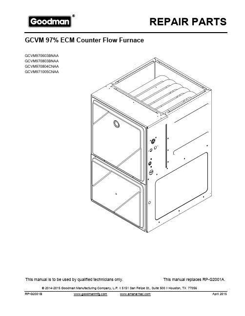
REPAIR PARTS® nufacturing Company, L.P. ◊ 5151 San Felipe, Suite 500 ◊RP-G2001BThis manual is to be used by qualified technicians only.This manual replaces RP-G2001A.April 2015GCVM 97% ECM Counter Flow Furnace© 2014-2015 Goodman Manufacturing Company, L.P. ◊ 5151 San Felipe St., Suite 500 ◊ Houston, TX 77056GCVM970603BNAA GCVM970803BNAA GCVM970804CNAA GCVM971005CNAAImportant Information For assistance within the U.S.A. contact:Goodman Company, L.P.For assistance outside the U.S.A. contact:IndexFunctional Parts List Rev B: updates primary limit controlsIllustration and Parts......................................................................................................................................................................................................Views shown are for parts illustrations only, not servicing procedures AR - As Required NA - Not Available NS - Not Shown00000000 - See NoteQTY - Quantity Example (QTY 3) (If Quantity not shown, Quantity = 1)M - Model Example (M1) (If M Code not shown, then part is used on all Models)Text Codes:ExampleM1 - Model#1 M2 - Model#2 M3 - Model#3Expanded Model Nomenclature:Goodman Manufacturing Company, L.P. is not responsible for personal injury or property damage resulting from improper service. Review all service information before beginning repairs.Warranty service must be performed by an authorized technician, using authorized factory parts. If service is required after the warranty expires, Goodman Manufacturing Company, L.P. also recommends contacting an authorized technician and using authorized factory parts.Goodman Manufacturing Company, L.P. reserves the right to discontinue, or change at any time, specifications or designs without notice or without incurring obligations. 2Consumer Affairs DepartmentGoodman Manufacturing Company, L.P.7401 Security Way Houston, Texas 77040877-254-4729-Telephone 713-863-2382-FacsimileInternational DivisionGoodman Manufacturing Company, L.P.7401 Security Way Houston, Texas 77040713-861-2500-Telephone 713-863-2382-Facsimile 4 - 113RP-G2001BFunctional PartsPartNo:Description:20162904*PRIMARY LIMIT-TEMPERATURE CONTROL(M2)*Refer to service bulletin SF-0540130F00038AUX LIMIT - LT BLUE 120º (QTY 2)0163F00017BECKETT BURNER (QTY 3)0271F00161BLOWER SHELL & WHEEL ASSY (M3, M4)0271F00159BLOWER SHELL & WHEEL ASSY (M1, M2)0130F00393DATA, FURNACE PCB (M1)0130F00394DATA, FURNACE PCB (M2)0130F00395DATA, FURNACE PCB (M3)0130F00396DATA, FURNACE PCB (M4)0130F00010FLAME SENSOR0151M00024GAS VALVE0257F00282HEAT EXCHANGER ASSY. (M2)0257F00284HEAT EXCHANGER ASSY. (M4)0257F00311HEAT EXCHANGER ASSY. (M1)0257F00312HEAT EXCHANGER ASSY. (M3)0130F00008IGNITOR-SINI 17 SEC0130M00141INDUCTOR, 5.9 AMPS (GMPE100-4) (M3, M4)0130M00243INTERLOCK SWITCH10123529MANUAL RESET R.O.S. LIMIT (QTY 2)0131M00272MOTOR, 1 HP, SERIAL ECM (M4)0131M00270MOTOR, 1/2 HP, SERIAL ECM (M1, M2)0131M00271MOTOR, 3/4 HP, SERIAL ECM (M3)0171M00003MOTOR-ID, BLOWERPCBKF202PCB, FURNACE CONTROL20162901PRESSURE LIMIT-RED (M3)0130F00481PRESSURE SWITCH (-.1 (COL BOX))0130F00482PRESSURE SWITCH (-.17 /-.86) (M1, M2, M3)0130F00483PRESSURE SWITCH (-.17 /-.86) (M4)0130F00036PRIMARY LIMIT - PINK (M1, M4)0130M00140TRANSFORMER 120V TO 24V, 40VASPECIAL PARTS0161F00000P GOODMAN NAMEPLATEExpanded Model NomenclatureM1 - GCVM970603BNAAM2 - GCVM970803BNAAM3 - GCVM970804CNAAM4 - GCVM971005CNAARP-G2001B 3Cabinet 4RP-G2001BCabinetRef. No:PartNo:Description:Ref.No:PartNo:Description:Image 1:GASKET (QTY 2)0154F00024111GASKET (QTY 2)0154F00025121DOOR, ACCESS 17.5 PNT (M1, M2)0121F00291DG191DOOR, ACCESS 21 PNT (M3, M4)0121F00292DG191DOOR, BLOWER 17.5 PNT (M1, M2)0121F00288DG201DOOR, BLOWER 21 PNT (M3, M4)0121F00289DG201VIEW PORT BUSHING-BLOWER DOOR (QTY 2)B1392139281GASKET, DECK (M1, M2)0154F00020311GASKET, DECK (M3, M4)0154F00021311PIPE, STRAIGHT CF (QTY 2)0161F00064441PIPE GROMMETM0501301451BUTTON PLUGM0570808491BUTTON PLUGM0570806501PLUG, HOLE0161M00027521HOSE CLAMP (QTY 2)0163M00049611UNIVERSAL BUSHING UB 875B1392104741BUTTON PLUG (QTY 2)M0310345NSBUTTON PLUGM0570807NSCF DRAIN TUBE ASSY (M1, M2)0270F03125NSCF DRAIN TUBE ASSY (M3, M4)0270F03126NSCF DRAIN TUBE ASSY (M1, M2)0270F03514NSCF DRAIN TUBE ASSY (M3, M4)0270F03515NSDRAIN TRAP0161F00046NSGOODMAN NAMEPLATE0161F00000PNSSCREW-DECORATIVE (QTY 3)M0209730NSImage 2:DRAIN PART BAG ASSY CF0270F0314112BAG ASSY CF0270F0313922Expanded Model NomenclatureM1 - GCVM970603BNAAM2 - GCVM970803BNAAM3 - GCVM970804CNAAM4 - GCVM971005CNAA5 RP-G2001B Blower Assembly 6RP-G2001BBlower AssemblyRef.No:Part No:Description:Ref.No:Part No:Description:Image 1:BLOWER SHELL & WHEEL ASSY (M1, M2)0271F0015931BLOWER SHELL & WHEEL ASSY (M3, M4)0271F0016131BLOWER MOTOR GROMMET (M3, M4)A400270261MOTOR MOUNT BAND (M1, M2)0121M00038141MOTOR MOUNT BAND (M3, M4)10441601141MOTOR MOUNT ARM (M3, M4)10441501151MOTOR MOUNT ARM (M1, M2)B1376857151MOTOR, 1 HP, SERIAL ECM (M4)0131M00272181MOTOR, 1/2 HP, SERIAL ECM (M1, M2)0131M00270181MOTOR, 3/4 HP, SERIAL ECM (M3)0131M00271181TC SCREW (M3, M4)M022*******TC SCREW 1.25" (M1, M2)M025*******MACHINE SCREW (M3, M4)M0267144251MACHINE SCREW HWH 1/4-20 X 1-1/2 BZ (M1, M2)B1393323251WASHER, FLAT 1/4 ID X 1 OD (M1, M2)B1392918261WASHER-FLAT (M3, M4)M027*******KEPS NUT (M3, M4)M028*******LOCKNUT, NYLON, INSERT 1/4, 20 (M1, M2)B1393800281TRANSFORMER 120V TO 24V, 40VA0130M00140381INDUCTOR, 5.9 AMPS (GMPE100-4) (M3, M4)0130M00141391PCB, FURNACE CONTROL PCBKF202401COVER, CONTROL BOARD0161F00014411CONTROL MOUNT PANEL0121F00094461AUX LIMIT - LT BLUE 120º (QTY 2)0130F00038521SLIT LOCK WASHER (M3, M4)B1392820621CONTROL HARNESS0259F00040NS DATA, FURNACE PCB (M1)0130F00393NS DATA, FURNACE PCB (M2)0130F00394NS DATA, FURNACE PCB (M3)0130F00395NS DATA, FURNACE PCB (M4)0130F00396NS PLASTIC PLUG, 1" (2713-BLK) (QTY 4)B1392021NS POWER HARNESS HIGH VOLTAGE 0259F00041NS WIRE HARNESS-BLOWER0259F00024NS*If end bells are needed please order the following: 0131M00182 - 1/2 HP 0131M00183 - 3/4 HP 0131M00184 - 1 HPExpanded Model Nomenclature M1 - GCVM970603BNAA M2 - GCVM970803BNAA M3 - GCVM970804CNAA M4 - GCVM971005CNAA7RP-G2001B Chassis 8RP-G2001BChassisRef. No:PartNo:Description:Ref.No:PartNo:Description:Image 1:PAINTED BASE PAN-21" C (M3, M4)0121F00435DG11PAINTED BASEPAN-17.5" CF (M1, M2)0121F00427DG11DECK-BLOWER, 17.5" CF (M1, M2)0121F0042531DECK-BLOWER, 21" CF (M3, M4)0121F0043331INSULATION, HT EXCHANGER 17.5" (M1, M2)0160F0001591INSULATION, HT EXCHANGER 21" (M3, M4)0160F0001691ANGLE, DECK (M1, M2)0121F00314101ANGLE, DECK (M3, M4)0121F00315101TOP, PAINTED FURNACE 17.5" CF (M1, M2)0121F00426DG111TOP, PAINTED FURNACE 21" CF (M3, M4)0121F00434DG111ANGLE, SIDE (QTY 2)0121F00313121GASKET-FA (M1, M2)20179309151GASKET-FA (M3, M4)20179310151INSULATION-BACK 17.5" (M1, M2)0160F00012161INSULATION-BACK 21" (M3, M4)0160F00013161INSULATION, SIDE (QTY 2)0160F00018171HARNESS-WIRING0159F0005018125" PRESSURE SWITCH HOSES (M3, M4)0164M00029191PRESSURE SWITCH HOSE (M1, M2)0164M00012191HOSE-PRESSURE SW 6"0164M00019201INTERLOCK SWITCH0130M00243221ELBOW-FLUE, 17.5" CFLOW (M1, M2)0164F00003241ELBOW-FLUE, 21" CFLOW (M3, M4)0164F00004241MOTOR-ID, BLOWER0171M00003271COUPLING0161F00037281PRESSURE SWITCH (-.1 (COL BOX))0130F00481291PRESSURE SWITCH (-.17 /-.86) (M1, M2, M3)0130F00482301PRESSURE SWITCH (-.17 /-.86) (M4)0130F00483301JUNCTION BOX PLA0161F00042311JUNCTION BOX LID0161F00043331PLUG-TUBEM0326804701GASKET (QTY 2)0154F00015791GASKET (M1, M2)0154F00014811GASKET (M3, M4)0154F00016811BRACKET, DOOR SWITCH0121F00389991PRESSURE SWITCH HOSE (M3, M4)0164M00008NSExpanded Model NomenclatureM1 - GCVM970603BNAAM2 - GCVM970803BNAAM3 - GCVM970804CNAAM4 - GCVM971005CNAA9 RP-G2001B Heat Exchanger / Manifold / Gas Valve 10RP-G2001BHeat Exchanger / Manifold / Gas ValveRef. No:PartNo:Description:Ref.No:PartNo:Description:Image 1:IGNITOR-SINI 17 SEC0130F0000811GAS VALVE0151M0002421ORIFICE (QTY 3)0163F0000431FLAME SENSOR0130F0001041MANUAL RESET R.O.S. LIMIT (QTY 2)1012352951MANIFOLD (M1)0163F0000861MANIFOLD (M3)0163F0000961MANIFOLD (M4)0163F0001061MANIFOLD (M2)0163F0001461BECKETT BURNER (QTY 3)0163F0001771BRACKET-BURNER 3 (M1)0121F0045581BRACKET-BURNER 4 (M2, M3)0121F0045481BRACKET-BURNER 5 (M4)0121F0045381ORIFICE BRACKET-BURNER 3 (M1)0121F00458111ORIFICE BRACKET-BURNER 4 (M2, M3)0121F00457111ORIFICE BRACKET-BURNER 5 (M4)0121F00452111COVER, FRONT (M4)0161F00027131COVER, FRONT (M2)0161F00031131COVER, FRONT (M1)0161F00056131COVER, FRONT (M3)0161F00065131GASKET, FRONT (M1, M2)0154F00011141GASKET, FRONT (M3, M4)0154F00012141HEAT EXCHANGER ASSY. (M2)0257F00282151HEAT EXCHANGER ASSY. (M4)0257F00284151HEAT EXCHANGER ASSY. (M1)0257F00311151HEAT EXCHANGER ASSY. (M3)0257F00312151TUBE PLUGM0326804161CAP-VINYL .500A1781105231COVER, REAR (M1, M2)0121F00317261COVER, REAR (M3, M4)0121F00318261GASKET, REAR CVR (M1, M2)0154F00037271GASKET, REAR CVR (M3, M4)0154F00038271*PRIMARY LIMIT-TEMPERATURE CONTROL (M2)20162904371*Refer to service bulletin SF-054PRESSURE LIMIT-RED (M3)20162901371PRIMARY LIMIT - PINK (M1, M4)0130F00036371PRIMARY LIMIT-HEAT SHIELD0121F00439NSSHIELD, COIL (QTY 2)0121F00355NSExpanded Model NomenclatureM1 - GCVM970603BNAAM2 - GCVM970803BNAAM3 - GCVM970804CNAAM4 - GCVM971005CNAA11 RP-G2001B 。
- 1、下载文档前请自行甄别文档内容的完整性,平台不提供额外的编辑、内容补充、找答案等附加服务。
- 2、"仅部分预览"的文档,不可在线预览部分如存在完整性等问题,可反馈申请退款(可完整预览的文档不适用该条件!)。
- 3、如文档侵犯您的权益,请联系客服反馈,我们会尽快为您处理(人工客服工作时间:9:00-18:30)。
一、概述
爱力浦公司主要从事柱塞计量泵、机械隔膜计量泵、液压隔膜计量泵及其他特种泵的研究、开发、生产和销售。
本公司生产的计量泵,其技术参数、检验规则等均严格执行国家标准GB7782-1996《计量泵》的各项规定。
计量泵按液力端分为柱塞式和隔膜式两大类。
按机座有J-X、JYMX、J-X2、JYMX2、J-Z2、JYMZ2、J-Z、JYMZ、J-D、JYMD、J-T、JYMT、JWM、JXM、JZM、JDM十六个系列。
通常以单联参数供用户选用,也可根据需要实现同机座同规格的多联组合和不同机座不同规格的组合,特别适用于工艺流程中多组份介质的比例输送。
计量泵的流量调节有两种:一是采用改变泵的柱塞行程长度(最佳相对行程长度为30-100%),调节可以在停机或运行时进行。
因其计量精度在¡1%以内,故又具有计量仪之功能(对于手动调节,以调量表、千分尺来指示泵的相对行程长度值;对于自控、遥控、及计算机流程控制等调节方式,另见各调节方式使用说明书)。
二是采用变频器改变输入的电源频率调节泵速,以便于实现流量调节的自动控制、程序控制和远程控制目的
本公司生产的计量泵适于输送温度为-30~100℃,粘度为0.3~800mm2/s的不含固体颗粒的液体。
计量泵具有绝无泄漏的优点,故适于输送易燃、易爆、易挥发、强腐蚀、放射性、剧毒、悬浮液以及昂贵液体。
特别是带有报警装置的隔膜计量泵,能在隔膜破裂后2秒内即发出报警,保证了操作人员及流程的安全(详见《隔膜破裂报警装置使用说明书》)。
本公司一贯坚持以质量求生存的服务原则。
经过多年的努力,产品已广泛应用于石油、化工、电力、原子能、医药、食品、环境保护、纺织和矿山等行业,并取得良好的市场效应。
同时欢迎提出宝贵意见,使我们的产品和服务做得更好!
本说明书仅对JWM-A型机械隔膜计量泵系列产品进行描述。
二、规格参数:
型号
额定
流量
(L/h) 最大 压力
(Mpa)
行程 (mm) 泵速 (spm) 隔膜直径 (mm)
接口尺寸 (mm)
重量 (Kg)
电机功率 (W)
备注
JWM-A6.5/1 6.5 2 54 JWM-A12/1
12 2
108 JWM-A24/1 24 4 90
7.3
JWM-A32/1 32 1
4 13
5 JWM-A42/0.
6 42
5 135 JWM-A60/0.3 60 0.6
5 150 Ф65
7.4
JWM-A80/0.5 80 4 150 JWM-A90/0.5 90 5 135 JWM-A100/0.5 100 0.5
5 150 Ф84
单相感应电机
电容启动2.5uF 40W 220V/50HZ 1350rpm
三相感应电机
380V/50HZ 1350rpm
40W 4P
JWM-A110/0.3 110 4 150 JWM-A120/0.3 120
5 135
JWM-A140/0.3 140 5 150 JWM-A150/0.3 150
0.3
5
180
Ф94
ID: Ф9 OD: Ф15
8.5
单相感应电机 电容启动2.5uF 40W 220V/50HZ 1350rpm 三相感应电机 380V/50HZ 1350rpm
40W 4P
运转中可手动调整流量
三、安装
1.安装前的注意事项
1)本泵一般为输送带腐蚀性液体介质,所以请尽量安装在通风良好、无
灰尘、干燥之处;
2)如安装夹纱管,务必锁紧,以免介质泄漏;
3)请勿将泵及药槽安装在日光直接照射处;
4)泵头箭头请朝上,泵体基座水平安装;
5)请勿安装在易接触蒸汽或腐蚀性气体之处;
6)泵安装环境温度为-20~+50℃范围内,高度在海拔1000米以下。
2.注射阀安装(仅限流量为6.5-100L/H计量泵)
如果向管道或者密闭容器中投加药液时,可在药剂投加点安装注射
阀,安装方法如(图1)所示,注射阀出口为1/2英寸管螺纹。
如所投加的管道或容器中有压力时,可防止药液倒流至计量泵出口管道内,
如计量泵入口管路有压力,药液可直接流经计量泵至投加管道或容器中,
发生虹吸现象,致使计量泵工作时计量不准确。
加装注射阀则可解决此类问题。
3.电源接线
1)电机标识上显示电机规格,请确认电源与电机规格是否符合,若不符
合,电机会造成烧损,请注意;
2)单相电机的电机与电容之间有配线,请将电源线直接接在电源上;
3)三相电机三线与电源相接,回转方向左右均可。
图1
1)运转前请确认计量泵进、出口管路及其他附件连接是否牢靠。
2)松开放气阀,开启计量泵,确认管路内空气排净后关闭放气
阀。
3)如所投加的药剂遇水发生化学反应,请将进出口阀及注射阀
拆出晾干后,从新装入再运行。
五、泵流量调节
请参照结构图1
1)请松掉锁紧螺丝(12);
2)旋转调量手轮(10)至所需刻度处对准红线即可;
3)调节完毕后请拧紧锁紧螺丝(12),如未拧紧,泵在运转过
程中流量会发生变化。
六、膜片更换
请参照结构图3
卸下内六角螺钉(29)、(30),卸下泵头。
旋转调量手轮至¡0¡位,将膜片左旋拧下。
旋转调量手轮至¡10¡位,将膜片右旋拧上。
装上卸下的内六角螺钉,各内六角螺钉应均力拧紧。
注射阀分解图
七、工作原理
下驱动顶杆及膜片做往复运动;调量机构采用调量手轮,调量手轮具有偏
心结构,通过旋转调量手轮调节其偏心位置,可调节顶杆行程大小,从而
达到调节流量大小的目的。
偏心轮组件为动凸轮、调量手轮为静凸轮,两
者组成双凸轮机构,相互配合使用,如图3
偏心机构采用偏心轴(16)和轴承(15)、(17)组成偏心轮组件。
偏
心轴被轴承(17)固定在机座(1)上,其一端套入减速电机轴头,另一端
固定有轴承(15)。
工作时偏心轴同减速电机一起做旋转运动,轴承(15)
作偏心旋转。
顶杆(9)在轴承(15)和弹簧(7)的相互作用下做往复直
线运动。
从而驱动膜片(27)做挠曲运动。
调量机构采用调量手轮(10)。
调量手轮采用偏心结构,偏心量与偏心轴偏
心量相等,且调量手轮偏心部分的直径与轴承(15)的最大直径相等。
当
其偏心部分处于最后端时,顶杆处于最大行程状态;当其偏心部分处于最
前端时,顶杆处于零行程状态。
旋转调量手轮即可从0%-100%调节顶杆行
程,从而达到调节流量的目的。
零件明细表
结构图
JWM-A 6.5-100L/H泵头分解图(材质:PVC) JWM-A 110-150L/H泵头分解图(材质:PVC)
性能曲线图
图12
入口
出口
出口
入口
外形尺寸图 典型的不锈钢泵头结构示意图
八、故障排除表
序号故障原因排除方法
1 完全不排液1.吸入高度太高
2.吸入管道阻塞
3.吸入管道漏气
1.降低安装高度或减少弯头阀门
2.清洗疏通吸入管道
3.压紧或更换法兰垫片
2 排液量不够1.吸入管道局部阻塞
2.吸入或排出阀内有杂物卡阻
3. 泵阀磨损,关闭不严
4. .转数不足
1.清洗疏通吸入管道
2.清洗吸排阀
3. 修理或更换阀件
4. 检查电机和电压
3 排出压力不稳定1.吸入或排出阀内有杂物卡住
2.排出管连接处漏油
3.安全阀或补偿阀动作失灵
1.清洗吸排阀
2.拧紧连接处螺钉
3.按安全阀补偿阀组的调试方法进行调整
4 计量精度不够1.充油腔内有残余气体
2.安全阀或补偿阀动作失灵
3.柱塞密封漏液
4.隔膜片发生永久性变形
5.吸入或排出阀磨损
6.电机转速不稳定
1.人工补油使安全阀跳开排气
2. 按安全阀补偿阀组的调试方法进行调整
3.调整或更换密封圈
4.更换隔膜片
5.更换新件
6.稳定电源频率和电压
5 运转中有冲击声1.传动零件松动或严重磨损
2.吸入高度过高
3.吸入管道漏气
4.介质中有空气
6.吸入管径太小
1.拧紧有关螺丝或更换新件
2.降低安装高度
3.压紧吸入法兰
4.排出介质中空气
6.增大吸入管径
6 输送介质油污染 1.隔膜片破裂 1.更换新件。