HL4000系列高性能蝶阀
海尔VQ400M系列类A安全组合阀门产品说明书

VQ400M SERIESCLASS “A” COMBINATION VALVESPRODUCT HANDBOOKAPPLICATIONFigure 1 VQ420M & VQ425MFigure 2 VQ440M & VQ450MThe VQ400M Series class “A” safety combination valves are used for control and regulation of gaseous fluids in gas power burners, atmospheric gas boilers, melting furnaces, incinerators and other gas consuming appliances.The VQ400M offers flexibility to mount accessories like valve-position indicator, pressure indication switches, vent-valves or by-pass valves at several positions at the gas valve, whenever, wherever. These combination valves are available in two body sizes:∙ Small modelo VQ420 o VQ425∙ Large modelo VQ440 o VQ450All models are connected at suitable sized gas pipes by flange kits which can be ordered separately in several sizes.CONTENTSVQ400M SERIES (1)CLASS “A” COMBINATION VALVES (1)APPLICATION (1)Contents (2)FEATURES (2)DESCRIPTION (3)SPECIFICATION (3)Models (3)Dimensions (3)Pipe sizes (4)Capacity (4)Connections (4)Torsion and bending stress (4)Supply voltages (4)Electrical equipment (4)Electrical connections (5)Ambient temperature range (5)Coil insulation solenoid valves (5)Enclosure (5)Body material (5)Closing spring (5)Valve plunger (5)Seals and gaskets (5)Power consumption (5)PERFORMANCE CHARACTERISTICS (6)Opening time (6)Closing time (6)Maximum working frequency (6)Duty cycle (6)Operational voltage range (6)Designed life time (6)CAPACITY CURVES (7)INSTALLATION (8)IMPORTANT (8)WARNING (8)Maintenance and service (8)Mounting position (8)Mounting location (8)Main gas connection flanged valves (9)WARNING! (9)Electrical connection (9)WARNING (9)Wiring (9)ADJUSTMENTS AND FINAL CHECKOUT (11)CAUTION (11)2nd main valve fast opening (11)2nd main valve slow opening (11)IMPORTANT (11)Final checkout of the installation (12)OPTION INSTALLATION (13)WARNING (13)CONSTRUCTION AND WORKING PRINCIPLES (13)ORDERING INFORMATION (14)NOTE (14)Replacement of parts (15)Warning (15)Recommended accessories (15)APPROVALS (17)Declaration of Conformity ........... Error! Bookmark not defined.FEATURES∙Class “A” safety combination valve forcontrol of gaseous fluids in gas consumingappliances in accordance with internationalstandards.∙Main body with two gas valves with single seat.∙Possibility of installing internal by-pass valve to achieve high-low flame control.∙Possibility of installing internal or external pilot valve.∙Possibility of installing vent valve.∙Possibility of installing flanged minimum and maximum pressure switches.∙Possibility of installing valve ProvingSystem (VPS).∙Possibility of mounting Closed Position Indication switch (CPI) at bottom of safetyvalve V1 and / or valve V2.∙Closing time: < 1 second.∙ Coils field replaceable.∙Coils suitable for permanent energizing.∙Fine mesh screen between inlet flange and main body (optional).∙Various pressure tap points at main body available∙Second main valve, either with adjustable flow regulator (fast), or characterizedopening mechanism (slow) with adjustablemaximum flow rate and step pressure.∙Rectifier boards field replaceable.∙PG11 cable strain relief standard atVQ400M.∙Plug connector according to ISO 4400 / DIN EN 175301-803 optional for VQ400M.DESCRIPTIONThe VQ400M Series combination valves are suitable for the control of gaseous fluids in gas consuming appliances according to international standards.The VQ400M Series combination valves meet the class “A” specification according EN161. TheVQ400M Series combination valves can be ordered with straight flanged pipe connection from 1/2 " up to 2". The VQ400M Series combination valves are standard equipped with two safety valves V1 andV2. The first valve (V1) is always fast opening. The second valve (V2) can be either fast or slow opening.∙Standard the second valve (V2) is supplied with throttle screw (fast opening with flowregulation).∙Optionally the second valve (V2) can be ordered with slow opening device (with flowregulation and adjustable opening).∙Optionally the second valve (V2) can be ordered fast open, without any regulationdevice.SPECIFICATIONThe specifications described in this chapter are related to the main gas valves.ModelsModels can be ordered according order specification numbering which is shownin Figure .15For an overview of all known combinations see surveys:∙ 50040300∙ 50040301 (Accessories) The VQ400M series combination valves areavailable in two body sizes:∙ Small modelo VQ420Mo VQ425M∙ Large modelo VQ440Mo VQ450MAll models are connected at suitable sized gaspipes by flange kits which have to be orderedseparately.DimensionsMain dimensions of the models are given atinstallation drawings:Table 1 Overview of installation drawings.Model Installationdrawing VQ420M INST0171VQ425M INST0172VQ440M INST0169VQ450M INST0170 Installation drawings are available in Honeywell documentation centre “HotDocs” and can besupplied digitally on request through Honeywellsales representative.Pipe sizesFor connecting with several pipe sizes it is recommended to mount Honeywell flange kits which can be ordered separately as indicated below.Table 2 Overview of recommended pipe sizes.Gas valve Recommended pipe size OptionVQ420M ½” 1 VQ420M ¾” 2 VQ425M 1”VQ440M 1¼” 1 VQ440M 1½” 2 VQ450M 2” Recommended flanges for each model to be mounted are given in table 3 and table 4. CapacityMain body: see capacity curves at Figure . Maximum operating pressure is 360 mbar for all models∙ 360 mbaro VQ420Mo VQ425Mo VQ440Mo VQ450M ConnectionsAs shown in the figure below, VQ400M is provided with plugs and flanges giving flexibility to customize this combination valve with Honeywell accessories.Figure 3 Interfaces for possible accessoriesTorsion and bending stressPipe connections meet group 2 according to EN161 requirements.Supply voltagesVQ400 M series can be ordered for line voltage: ∙230 Vac, 50/60 Hz∙115 Vac, 50/60 Hz∙120 Vac, 50/60 HzElectrical equipmentAC rectified coils with separated rectifier inside the cover.Plugs for mounting:∙pressure tap∙Valve provingsystem∙Pressure switchesPlugs for connecting:∙By pass valve∙Internal or externalpilot valve∙Vent valveFlange connection V2In the bottom plate twoplugs are available formounting ClosedOutlet flange Inlet flangeFlange connection V1Plug for mountingpressure tapElectrical connectionsVQ400M: standard plug connection accordingPG11 on main gas valves and additional valves. Optional: three pin plug connector (…DIN plug“) on main gas valves and additional valves.Ambient temperature rangeVQ400M is designed to operate in ambient temperature levels between: -15 ... 60 °CCoil insulation solenoid valves Insulation material is specified according class F. EnclosureIP54 in combination with PG11 connection.IP65 in combination with DIN-plug connection.Body materialAluminum alloy die cast body.Closing springAISI 302 steelValve plungerChrome plated Fe 360B steel sliding on anti-friction bearing.Seals and gasketsHydrocarbon resistant NBR rubber type Power consumptionHoneywell provides VQ400M with coils that suit demands of specified inlet pressure levels. An overview of power consumption for different applications is given in the table below.Table 3 Power consumption of each VQ400M main valve for360 mbar applications.115V120V230VVQ420M 16,5 18 15VQ425M 23,9 26,1 21,1VQ440M 52 56,7 46,5VQ450M- - 61PERFORMANCE CHARACTERISTICSOpening timeThe first valve (V1) opens in less than 1 second.The second valve (V2) can be either a fast opening valve which opens in less than 1 second or a characterized opening valve which is adjustable from 1 up to 30 seconds, at rated capacity.The opening characteristic is factory set at approximately 6 seconds at the following conditions:∙measured at 80 % of rated capacity∙30 mbar supply pressure∙ nominal voltage∙ 20 °C∙2,5 mbar pressure drop∙no step pressureDue to the influence of ambient temperature (-15 ...60 °C) the adjusted opening time of 6 seconds measured at 80% of adjusted flow rate can vary +/- 4 seconds.Closing timeLess than 1 second for both valves. Maximum working frequencyVQ400M is equipped for maximal working frequency of one cycle per minute.Duty cycleCoils are suitable for permanent energizing. Operational voltage rangeThe combination gas valve will function satisfactory between 85% and 110% of the rated voltage.Designed life timeOverview of designed life time is given in the table below.Table 4 Number of cycles per model.Model Number of cyclesVQ420MA 500.000VQ425MA 500.000VQ440MA 300.000VQ450MA 300.000CAPACITY CURVESFor comparison an overview of specified capacity of VQ400M is shown in table 5. Table 5 Overview of reference capacity in m3/h air at ∆p = 2.5 mbar.Gas valve Flange size Pipe size Flow capacityVQ420MA DN15 ½” -VQ420MA DN20 ¾” 8VQ425MA DN25 1” 11¼” 25VQ440MA DN32 1½” 31VQ440MA DN40 1VQ450MA DN50 2” 40In figure 4 a broader range of specified capacity for VQ400M is shown in curves.Figure 4 Capacity curve for VQ400M Series class …A” combination valves.INSTALLATIONIMPORTANT1. Read these instructions carefully. Failure tofollow the instructions could damage theproduct or cause a hazardous condition.2. Check the ratings given in the instructionsand on the product to make sure theproduct is suitable for your application.3. The installation has to be carried out byqualified personnel only.4. Carry out a thorough checkout wheninstallation is completed.WARNING∙Turn off gas supply before installation.∙Disconnect power supply to the valveactuator before beginning the installation toprevent electrical shock and damage to theequipment.∙Do not remove the seal over valve inlet and outlet until ready to connect piping.∙The valve must be installed so that the arrow on the valve points in the direction ofthe gas flow (gas pressure helps to closethe valve). Maintenance and serviceThe designed lifetime* of this product is 10 years, based on date code, according to:a) the standard EN 126b) the table on designed lifetime as stated onthe Afecor website /We cannot assume that the product can be safely used beyond the mentioned designed lifetime. This lifetime is based on use of the control according manufacturer’s instructions.Regular inspection of the control by authorized personnel in accordance with guidelines of the appliance manufacturer is required.After reaching the designed lifetime the product has to be replaced by authorized personnel.Note: * Warranty as opposed to designed lifetime is described in the delivery terms.Mounting positionThe gas valve can be mounted in vertical position with the coils at top side. The gas valve can be mounted plus or minus 90 degrees from the vertical.Mounting locationThe distance between the gas valve and thewall/ground must be at least 30 mm.Main gas connection flanged valves1. Take care that dirt does not enter the gasvalve during handling.2. Remove the flanges from the valve.3. Use a sound taper fitting with threadaccording to ISO 7-1 or new, properlyreamed pipe, free from swarf.4. Apply a moderate amount of good qualitythread compound to the pipe for fitting only;leaving the two end threads bare, PTFEtape may be used as an alternative.5. Screw the flanges onto the pipes.6. Ensure that inlet and outlet flanges are inline and separated from each other enoughto allow the valve to be mounted betweenthem without damaging the gasket.7. Place gasket. If necessary grease it slightlyto keep it in place.8. Mount gas valve between flanges using thebolts for each flange.9. Complete the electrical connections asinstructed in the electrical connectionsection.WARNING!Tightness test after installation∙Spray all pipe connections and gaskets with a good quality gas leak detectionspray.∙Start the appliance and check for bubbles.If a leak is found in a pipe connection,remake the joint. A gasket leak can usuallybe stopped by tightening the mountingscrews, otherwise, replace the gas valve. Electrical connectionWARNING∙Switch off power supply before making electrical connections.∙All wiring must comply with local codes, ordinances and regulations.Use lead wire which can withstand 105 °C ambient. The electric ON/OFF operator is provided with a terminal block for electrical connections.Wiring PG11Small models VQ420M-VQ425MRemove screws (A).Take off protective cover lids and gaskets (B). Take off plugs Pg11 from holes (Figure 5):(K) and (N) – for connecting separately.(K), (L) and (M) – for connecting bycommon supply from inlet side.(N), (L) and (M) – for connecting bycommon supply from outlet side.Figure 5 IP54 version closed by plugsPrepare cables∙Remove plastic outside insulation for about 50-75 mm.∙Strip wires from plastic insulation for about 5-7mm.Place cable support screw (C), steel ring(D), rubber ring (E) and guide wires through the hole in the cover to the connection block (F).Connect wires between plates by tightening the particular screws (F1, F2, F3)∙ Left: Phase∙Middle: Earth connection∙ Right: NeutralIf common supply:Loose screw (P) and cap (S). Turn coils and insert adaptor (G).Turn back coils and tight screw (P) and cap (S) by tightening torque 2,5 Nm.Connect corresponding contact by wires through adaptor.Tight cable support screws (C)Place gaskets and cover lids in position (B)Place screws (A) and tight.Figure 6 Small model connected by common supply from outlet sideLarge models VQ440M-VQ450MEach coil have to be supply separately.Remove screws (A)Take off protective cover lids and gasket (B)Take off one from two plugs Pg11.Prepare cables∙Remove plastic outside insulation for about 50-75 mm.∙Strip wires from plastic insulation for about 5-7mm.Place cable support screw (C), steel ring(D), rubber ring (E) and guide wires through the hole in the cover to the connection block (F).Connect wires between plates by tightening the particular screws (F1, F2, F3)∙ Left: Phase∙Middle: Earth connection∙ Right: NeutralTight cable support screws (C)Place gaskets and cover lids in position (B)Place screws (A) and tight.Figure 7 Large model – V2 coil connected from outlet side Wiring DIN plugFollow the instructions supplied by the appliance manufacturer as shown in the figures below. Coilssupply separateFigure 8 Three pin electrical plug connector (according to ISO 4400 / DIN EN 175301-803).ADJUSTMENTS AND FINAL CHECKOUTThe procedures described in this chapter are related to the adjustments on the main gas valve, pilot valve and by-pass valve. For adjustments on the other additional functionalities (e.g. pressure switch), refer to the included instruction sheet of the product in question in the package.CAUTION∙ Adjustments must be made by qualifiedpersonnel only.∙To ensure a safe closing of the valves, it is essential that voltage over the terminals of operators is reduced to 0 Volts.2nd main valve fast openingFigure 9 Adjusting flow rate.Flow rate adjustment (see Fig. 9.)1. Remove the cap screw from top of the coil.2. Place a socket head wrench into theadjustment nut. 3. Turn wrench counter-clockwise to increaseor clockwise to decrease flow rate. 4. Replace cap screw.2nd main valve slow openingThe following characteristics can be adjusted:∙ flow rate ∙ steppressure ∙ opening speedFigure 10 Characterized opening.IMPORTANTTo ensure a satisfactory setting of the valve the pressure drop over the valve should be at least 10% of the supply pressure or 2.5 mbar which ever is the greatest.Flow rate adjustment1. Remove the cap from top of the coil byloosening both screws. 2. Place a wrench on the adjustment hexagonnut. 3. Turn wrench counter-clockwise to increaseor clockwise to decrease the flow rate. 4. Replace cap on top of the coil.Figure 11 Adjusting flow rate.Step pressure adjustment (see fig. 12.)1. Remove the cap from top of the coil byloosening both screws. 2. Place a screw driver in the slot ofadjustment screw which is situated in center of the valve. 3. Turn screw driver counter-clockwise toincrease or clockwise to decrease step pressure. 4.Replace cap on top of the coil.Figure 12 Adjusting step pressure.Opening speed adjustment1. Remove the cap from top of the coil byloosening both screws. 2. Place screw driver in the slot of adjustmentscrew which is of center line. 3. Turn screw driver counter-clockwise toincrease the opening speed and therefore the time till full opening will decrease. 4. Turn screw driver clockwise to decreasethe opening speed and therefore the time till full opening will increase. 5.Replace cap on top of the coil.Figure 13 Adjusting opening speed.Final checkout of the installationSet the appliance in operation after any adjustment and observe several complete cycles to ensure that all burner components function correctly.OPTION INSTALLATIONInstallation can be done by the OEM or by qualified personnel in field.WARNINGIf additional hardware needs to be installed on field, then installation personnel should take care, that the main gas flow to the appliance has been completely stopped by an upstream manual shut-off valve prior to the installation.Installation1. Open the required gas flow channels byremoving the suitable plugs from the valvebody.2. Take care that dirt can not enter the gasvalve during handling3. Install the screw-in additional hardware asrequired (vent, by-pass, external pilotvalve)4. Please refer to the relevant instructionsheetCONSTRUCTION AND WORKINGPRINCIPLESThe VQ400M combination gas valves are 2 x class “A” fail safe shut-off valves. The valve is opened by energizing the direct ON / OFF operator. The direct ON / OFF operator consists of a coil and stopsleeve assembly. Inside the top sleeve assembly a plunger is placed which is able to move up anddown and thus opening or closing the valve. Theplunger is gliding on two anti-friction bearings. Flow regulation is done by adjustable plunger stroke. A strainer made out of steel AISI 303 is incorporated between inlet flange and main body. Valve closingSECTION A-AFigure 14 Schematic drawing of VQ400M.Moveable valve toopen / close flowchannelAutomatic closing mechanismwhen power is switched offdeviceElectro-magneticactuatorFlow directionORDERING INFORMATIONFigure 15 Ordering information VQ400M Series combination valves. NOTEAccessories as flanges need to be ordered separately.REPLACEMENT OF PARTS Warning∙Take care that only qualified persons carry out the installation of parts, accessories,and add on components.∙Follow the installation instructions included in the package.∙Check that the selected part, accessory or add-on component is the correct one forthe application in question.∙Replace old gaskets with the new ones supplied in the package and check forleakage when the supply is switched onagain.∙After installation and/or replacement has been completed, a gas leak test must becarried out.∙Also check the gas valve for satisfactory operation after fitting accessories.Table 6 Rectifier boards for VQ400M series.Gas valve Rectifier board115V/120V Rectifier board230VVQ420MA CS020020 CS020070 VQ425MA CS020020 CS020070 VQ440MA CS020020 CS020071 VQ450MA CS020020 CS020071 RECOMMENDED ACCESSORIESThere are two different series of flange kits available. The first series of flange kits consist of: 1 flange with sealing plug, 1 O-rings and 4 screws.Table 7 Flange kits without strainer.Gas valve Recommended flange kitVQ420M KTCOMB15VQ420M KTCOMB20VQ425M KTCOMB25VQ440M KTCOMB32VQ440M KTCOMB40VQ450M KTCOMB50The second series of flange kits consist of: 1 flange with sealing plug or cast pressure tap, 1 strainer, 1 O-rings and 4 screwsTable 8 Flange kits with strainer.Gas valve Recommended flange kitVQ420M KTCOMS15VQ420M KTCOMS20VQ425M KTCOMS25VQ440M KTCOMS32VQ440M KTCOMS40VQ450M KTCOMS50Table 9 Overview of recommended internal by-pass valves. Gas valve Internal by pass valveVQ400M VB420XxxxxSee Honeywell documentation VB420Xxxxx KIT for further instructions on internal by-pass valves. Table 10 Overview of recommended external pilot valves.Gasvalve ExternalpilotvalveVQ400M VP420XxxxxSee Honeywell documentation VP420Xxxxx KIT for further instructions on external pilot valves.Table 11 Overview of recommended vent valves.Gas valve Vent valveVQ400M VV420XxxxxSee Honeywell documentation VV420Xxxx KIT for further instructions on vent valves. Table 12 Overview of recommended closed position indication switches (CPI).Gas valve Closed position indicatorVQ420M MS062001VQ425M MS062501VQ440M MS064001VQ450M MS065001Table 13 Honeywell fine particle filter.Gasvalve HoneywellFilterVQ420M HFVR050/HFVR150VQ425MThis filter is used to filter fine (50 or 150 µm) particles of dirt out of gas flow.HoneywellHoneywell Building Technologies Environmental & Energy Solutions Honeywell Technologies Sàrl Z.A. La Pièce 16 1180 Rolle (VD) – CHSTANDARDS AND APPROVALS。
Marsh Hawk TRV 1系列4000压力释放阀说明书

v e n t i n g| g a u g e h atc h e sS E R I E S4000 M A R S H H AW K T RVFeatures• Premium deep-set gauge hatch with integral pressure & vacuum relief offers superior performance in normal and cold conditions.• reliable, bubble-tight sealing with standard Fkm ( viton) seal and stainless steel spring.• Field adjustable pressure settings, from 2 ozsi to 32 ozsi.• manual relief, inconel trim, alternative seals and various coatings optionally available.F E AT U RE SDeep-set venting gauge hatch• the series 4000 marsh hawk trv offers tank access combined with pressure and vacuum reliefin a deep-set design.• situating valve seats below the tank roof permits latent heat from the product to keep the seals ice-free.Reliable, bubble-tight sealing• the series 4000 has class-leading sealperformance as compared to any other premium or economy venting gauge hatch currently available.• improved sealing performance eliminates flutter and periodic small-scale venting which can cause frost closure in competitor top-mount hatches.Variety of pressure settings• the series 4000 marsh hawk pressure relief is adjustable between 2 ozsi and 16 ozsi in 2 ozsi increments.• the optional double-weight spring allows relief pressure between 18 and 32 ozsi, in 2 ozsiincrements.• 1 ozsi increments optionally available.• vacuum relief is fixed at 0.4 ozsi.Suitable for Sour Service• the series 4000 is ready for sour service out of the box with Fkm ( viton) seals and stainlesssprings.• For more adverse applications, alternative seal and spring materials are available, along withhard anodization or fusion-bond epoxy coatings.S P E C I F I C AT I O NS¹temperatures provided are continuous service temperatures for the indicated seal materials. see the short term extended service temperatures below in “seal materials and configuration” section.D I M E N S I O NSFalse-colour cutaway of a series 4000 marsh hawk trv showing the deep-set seal (orange), pressure spacers(blue) and springs (red).F LOW C H A R AC T E R I S T I C-3.2-3-2.8-2.6-2.4-2.2-2-1.8-1.6-1.4-1.2-1-0.8-0.6-0.4-0.20T A N K V A C U U M , V (O Z S I )024681012141618202224262830323436384042444648505254565860626401234567891011121314151617181920212223242526272829303132333435T A N K P R E S S U R E , P (O Z S I )FL OW RA T E T H R O UG H M A R S H H AW K, Q , X 1000 SCF H (AIR)O P T I O N S A N D AC C E S S O R I E SManual Reliefthe manual relief option allows an operator to manu-ally activate the vent.Pressing the hatch cover’s large red button on the actu-ates the vacuum pallet, relieving pressure in the tank to allow safe removal of the spider cage assembly for tank gauging or hatch maintenance. the button and actuating poppet are supported independently of the vacuum disc, and do not interfere with normal relieving operation.Hard Anodized (Type III)For situations requiring improved corrosion resistance over the standard marsh hawk, a hard anodization option is available. this electrochemical process in-creases the thickness and durability of the ceramic-like natural aluminum oxide layer.all aluminum components are anodized to meet miL-a-862F type iii engineering hardcoat. the anodization slightly darkens the cast components and imparts a slight bronze tinge to the machined components.anodization improved performance in moderate brines, as well as acetic, boric and nitric acid. For prolonged exposure to concentrated brines, or strong mineral acids, consider the severe service coating.Severe Service CoatingFor situations demanding the highest corrosion resis-tance, consider the severe service coating.the body of the marsh hawk is coated with a red Fusion Bond epoxy (FBe) for resistance to mineral acids,(including sulphuric and hydrochloric acids up to 15%) high-chloride ion solutions (including alumi-num chloride, potassium chloride and brine) as well as many other petrochemicals.the marsh hawk internals are coated in a proprietary black PFa (teFLOn) providing the same excellent fluo-ropolymer chemical resistance as the FBe above.series 4000 marsh hawk trv with manual relief Optionseries 4000 marsh hawk trv with hard anodizationseries 4000 marsh hawk trv with severe service coatingO P T I O N S A N D AC C E S S O R I E S (C O N T I N U E D )S E A L C O N F I G U R AT I O N A N D M AT E R I A L S the series 4000 marsh hawk combines the pressure and vacuum valve in an innovative design that requires only one shared gasket.to improve valve sealing performance, gaskets are factory coated with a pliable silane-based sealant. an optional oil-based sealant for use in sour gas applica-tions is also available. Both sealants are available in small packages for maintenance and reapplication.hawkeye offers three material options for the pressure / vacuum seal, beyond the standard Fkm (viton®) seal.• For applications where sealing is the first priority and the vent is not expected to operate often and has low set pressures (under 4 ozsi), eFkm (sponge viton®) can be supplied.• For higher temperature, minimally freezing conditions and acid service FePm (aflas®) is available.• For extreme applications FFkm (kalrez®) is also available.the use of ePDm seals in any hawkeye vent is contra-indicated due to its unsuitability in common petrochem-ical applications.hawkeye does not offer or recommend using solid fluoropolymer (PtFe, PFa, FeP, etc.), nor expanded flu-ropolymer (gOre-tex®) as a gasket material and any venting device. although the material may be chemi-cally suitable, the harder crystalline polymer structure of these materials impedes sealing at the typically low interfacial pressures found in the marsh hawk, as well as other low-pressure (i.e. <15 psi) vents.GENE R A L FLU OROEL A STOM E R CHEM ICA L C OM PATI BI LI T Y¹FKM / VI TON N.B.¹ THIS CHART I S F OR R EFE REN CE ONLY. ALT HOUG H HAWKEYE STRI VES TO E NSU RE P RE SE NTE D I NF OR MATI ON I S ACCURATE, A QUALIF I ED PE RSON SHO ULD EN SURE TH E SUI TABILI T YO F A S E LECTED MATER IA L I N T HE SPECIF IC CHEMI CAL, TEMP ERATURE A ND PRE SSU RE C O NTE XT O F TH EI R APPLI CATIO N.² SH OWN F OR COMPA RI SON PURPOSE S ON LY, NOT AVA ILABLE AS A SEAL M ATE RIAL O N H AW KE YE VE N TS60330OPE R AT I NG TE M PE R ATU R E , °CNOR MA L RAN G EVITON IDHOLE AFLAS IDHOLES KALREZ ID HOLESID E N T IF Y IN G M AR S H H AWK GAS K E T M AT E R I A LMesh Hata formed 10 mesh 304 stainless steel cover to keep insects and debris from interfering with the marsh hawk internals.De-icing Systemallows direct injection of a seal-appropriate de-icing solution onto the marsh hawk internals from ground level. includes spray nozzle and hose assembly.PA RTS L I S T&M AT E R I A L S O F C O N S T R U C T I ONPAC K AG I N Gseries 4000 marsh hawks are shipped complete and boxed. in addition to the marsh hawk itself,the car-ton contains bolt kit(s), tank gasket(s) and installation instructions.weight is approximately 28 lb [12.7 kg].P R E S S U R E T E S T I N G series 4000 marsh hawks are tested prior to packaging to ensure pressure-tightness and relief setting accuracy. items passing the quality control measures are marked with the label at right.•P A S S•P R E SS UR E T ES T E DV E N T M A R K I N Gthe spider cage assembly of the series 4000 marsh hawk is tagged with the initial factory confi guration of the valve. as the relief pressure is fi eld-adjustable, space is left on the tag to record future set pressures,should they change.C E RT I F I C AT I O Nthe pressure and vacuum relief settings of the series 4000 marsh hawk can be factory certifi ed at an addi-tional expense. certifi ed hatches are accompanied by a certifi cate stating the relief pressure of the hatches.R I S E RS & S P O O L SBolt-on risers account for the slope of the tank roof ensuring the series 4000 marsh hawk sits level for trouble-free operation. adapter spools allow installa-tion of a marsh hawk or other 8” aPi 12B/F device onto an ansi B16.5 fl at-face fl ange or other aPi man-way or tank opening. see the “risers, spools & rings” brochure for more information. 12:1 Bolt-on Hatch Riserthe most popular riser used with the series 4000 marsh hawk, the HRSP-0800, ensures a vertical gauge hatch orientation on a 12:1 sloped tank roof with an existing 8” aPi 12B/F fl at-face connection.[in.][mm.]rh riser height (max) 4.2107rcmin minimum fl ange gap2.563.5P Pitch12:1 4.8°rd Outisde Diameter 12.0305riinside Diameter8.0203the series 4000 marsh hawk is just one part of tank-age product lines from hawkeye industries, that also includes:Vapor Controlseries 5000 ePrv series 6000 Pvrv Mechanical Level Indicationmodel 1000 Redtail & model 1500 Roadside Dry seal Zero emission Level gauging systems model 2000 Goshawk Level transmitter for Dry seal Zero emission Level gauging systemsR E L AT E D P R O D U C TScontents © 2006 - 2021 hawkeye industries inc. this document is uncontrolled, and is subject to change without notice. Please refer to for the most up-to-date product information. 2110 70 ave nwedmonton, aB, canada t6P 1n6toll Free: (800) 910-4295Phone: (780) 490-4295Fax: (780) venting - series 4000 marsh hawk trv 01Jun2021Printed in canada.O R D E R I N G I N F O R M AT I O Nstandard series 4000 marsh hawk configurations are stocked ready to ship. Other configurations are typically assemble-to-order and available in under two weeks. configure your desired series 4000 marsh hawk trv us-ing the part number legend below. items in bold are standard items and have fastest lead times. all series 4000 marsh hawks ship complete with a gr. 5 Bolt kit and cr (neoprene) Base gasket, both upgradable (see below). For project quantities, contact your hawkeye sales rep for delivery schedules.Relief & MaterialOptionsMHMSMesh ScreenMHKD De-icing System0000Accessories Base GasketBolting KitSeries 6000 PVRV。
全液控止回蝶阀说明书

全液控止回蝶阀HD T7Q42X-6 DN1600使用说明书铁岭阀门(集团)特种阀门有限责任公司1用途本蝶阀适用于于为水、海水或油品的泵出口管路上,兼有截断水流和止回阀两种功能。
阀门在关闭时具有二阶段缓冲功能,有效防止由于突然停电或事故停泵时产生圈套的水锤和压力波动,保护水泵和系统管路。
2特点2.1本阀门采用蓄能器取代了重锤液控蝶阀中的重锤,将重锤势能变成液体压力能,体积小重量轻、结构简单。
2.2本阀门的液压系统和电气控制箱与阀门分体安装,阀门即可水平安装,也可以垂直水平安装,便于安装和维护。
2.3本阀门液压系统和电气系统设计完善功能齐全,阀门既可就地操作,也可心垂直水平安装,便于安装和维护。
3主要规格和技术参数3.1性能规范3.2执行标准结构长度执行GB/T 12221~1989压力试验执行GB/T 13927-1992连接法兰执行GB/T 17241.6-19983.3本蝶阀的结构、主要外形尺寸、连接尺寸见附图1。
4主要零部件材料5阀门运行说明5.1开阀液压站上油泵启动,压力油经油管进入液动装置油缸无杆腔内,推动活塞带动蝶板从00(全关)到900(全开),完成阀门开启。
5.2关阀:蓄能器内压力油进入液动装置油缸有杆腔内,推动活塞带动蝶板完成阀门的快、慢两阶段关闭。
5.3开阀和关阀时间5.4手动关闭阀门:在备用电源失效的情况正下,可手动操作相应电磁阀,利用蓄能器的压力完成阀门关闭。
6液压系统说明6.1液压系统原理液压原理、动作顺序见图2、图36.2.1预备动作:阀门接通电源,油泵自动启动,蓄能器补压蓄能,当压力达到l6MPa时,SP2动作,油泵停止,蓄能器补压结束。
6.2.2开阀:按下开阀按钮,电磁铁YVl获电换向,油泵启动,压力油进入油缸无杆腔,油缸带动蝶板转动到达全开位置后凸块压动行程开关SO2,同时开启回路的压力达到压力继电器SP3预调值后油泵YV1失电复位,开阀结束。
高速2号件左侧节流阀可改变阀门开启时间。
HD7x43H蓄能器式液控缓闭阀门
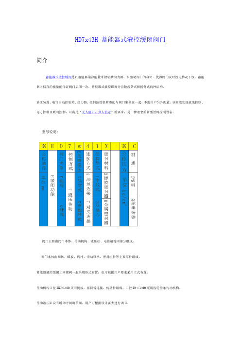
HD7x43H 蓄能器式液控缓闭阀门
简介
蓄能器式液控蝶阀是以蓄能器储存能量来做辅助动力源,来驱动阀门的启闭。
使得阀门及时没电情况下没,蓄能器内储存的能量能保证阀门启闭一次。
蓄能器式液控蝶阀分齿轮齿条式和摇臂式两种结构。
油压装置、电气自动控制箱、接力器、控制油管很紧凑的与阀门集聚在一起,不需用户另外配置。
该阀能实现就地控制、远方控制及联动控制,可满足“无人值班,少人值守”的要求,是一种理想的新型管路控制设备。
型号说明:
阀门主要由阀门本体、传动机构、液压站、电控箱等四部分组成。
阀门本体由阀体、蝶板、阀杆、滑动轴承、密封组件等主要零件组成。
蓄能器液控缓闭止回蝶阀一般采用卧式布置;也可根据用户要求采用立式布置。
传动机构口径DN≥1400采用侧板、摇臂等连接、传动件组成,口径DN<1400采用齿轮齿条传动机构。
传动液压缸设有缓闭时间调节阀。
用户可根据设计要去进行调节。
液压站包括油泵机组、手动泵、蓄能器、电磁阀、溢流阀、流
量控制阀、截止阀、液压集成块、油箱等零部件。
蓄能器系统中,蓄能器为阀门启闭提供主动力源。
流量控制阀用作开关阀时间调节,用户可根据设计要求进行阀门开关速度调节。
手动泵用作系统调试和特殊情况下的阀门启闭。
液压系统电磁换向阀特征为:电磁阀得电蝶阀工作、失电蝶阀保位锁定;采用其它作用型式应在订货时说明。
液压系统与阀门本体一般为分体安装,也可以整体安装。
用户未作特殊说明时为分体式安装。
蓄能器液控缓闭止回蝶阀采用立式布。
艾默生 A11 型高性能蝶阀说明书

2007 年 2 月A11 阀1W4641-1/ILW4642-1/IL图 1. A11 型蝶阀A11 型高性能蝶阀简介手册适用范围本指导手册介绍了 150、300 和 600 磅级的 A11 型高性能蝶阀(图 1)。
有关 900 和 1500 磅级的阀门, 请联系您的艾默生过程管理销售办事处。
有关执行机构和配件的信息,请参阅这些项目的独立指导手册。
未经完全培训获得安装、操作和维修阀门、执行机构和配件的资格的,且未仔细阅读和理解本手册内容的人员,不得安装、操作或维修 A11 型蝶阀。
如果您对本说明有任何疑问,请在操作前联系您的艾默生过程控制销售办事处。
D 500073X 012注意艾默生、艾默生过程管理或任何其附属实体均不 承担产品的选型、使用和维修责任。
产品的选型、使用和维修责任均由购买者和最终用户承担。
说明A11 型高性能蝶阀提供带各种阀封、阀体和内部组件的无法兰对夹式或单法兰式设计。
这些阀门拥有专利动态密封设计,可用于各种高要求的工况。
简介 ...........................................................................1手册适用范围 ..........................................................1说明 ........................................................................1技术规格 .................................................................3安装 ...........................................................................3调整行程止动装置 ....................................................3安装准备 ..................................................................4阀门定位 .................................................................4安装阀门 ................................................................6止推垫圈 ...............................................................7填料调整和阀轴焊接 ..............................................7维修 ...........................................................................8拆卸阀门 .................................................................9填料维修 .................................................................9套环 ....................................................................10润滑配件和吹扫连接器 .......................................10密封件维修 ...........................................................10软密封件安装 ......................................................11金属密封件和 Phoenix III 密封件安装 .................11低温密封件安装 ..................................................13阀轴/蝶板销钉组件的维修 .....................................13垫圈固定板 ...........................................................15轴承的维修 ...........................................................15零件定购 ..................................................................16零件清单 (17)2007 年 2 月A11 阀2表 1. 技术规格可用配置 阀门尺寸150 与 300 磅级:尺寸为 n 30、n 36、n 42 和 n 48 英寸600 磅级:尺寸为 n 3、n 4、n 6、n 8、 n 10、n 12、n 14、n 16、n 18、n 20 和 n 24 英寸阀体:磅级为 n 150/150、n 150、n 300、 n 600、n 900 和 n 1500 的对夹式和单法兰式 最大入口压力遵照标准 ASME B16.34,与可用的 ASME 标准的压力和温度等级的额定值一致,除非此类额定值受限于材料温度范围。
进口高压蝶阀参数

进口高压蝶阀参数
1.阀门尺寸:进口高压蝶阀通常有许多不同的尺寸可供选择,尺寸通常由阀门的内径和法兰连接的大小确定。
2. 阀门材质:阀门材质通常决定了它的使用寿命和适用范围。
进口高压蝶阀通常采用高强度不锈钢、碳钢或其他耐腐蚀材料制成。
3. 阀门操作方式:阀门可以手动或自动操作。
手动操作需要人工操作开关,而自动操作通常由电动或气动装置驱动。
4. 压力等级:进口高压蝶阀的压力等级通常由应用场景和使用要求决定。
常见的压力等级包括PN10、PN16、PN25、PN40等。
5. 适用介质:进口高压蝶阀通常适用于液体、气体、蒸汽等介质。
在选择阀门时需要考虑介质的流量、温度、压力等参数。
6. 法兰连接方式:进口高压蝶阀通常采用法兰连接方式,不同的法兰连接方式包括螺栓连接、对夹连接、焊接连接等。
7. 流量特性:进口高压蝶阀的流量特性通常由阀门的设计和结构决定,有时也可以通过调节阀门的开度来改变流量特性。
以上是进口高压蝶阀参数的一些基本介绍。
在选择阀门时,需要综合考虑各个参数的影响,选择最适合的阀门以满足使用要求。
- 1 -。
法兰式蝶阀参数

法兰式蝶阀参数详解1. 概述法兰式蝶阀是一种常用的流体控制阀门,广泛应用于工业领域。
它的特点是结构简单、重量轻、体积小、启闭迅速、流阻小等优点。
本文将详细介绍法兰式蝶阀的参数及其作用,以及使用注意事项。
2. 常见参数2.1 额定压力(PN)额定压力是指蝶阀在设计和制造时所能承受的最大压力。
常见的额定压力有PN10、PN16、PN25等级别。
需要根据实际工作环境来选择合适的额定压力,以确保阀门正常运行。
2.2 适用温度(T)适用温度是指蝶阀在设计和制造时所能承受的最高温度。
通常使用的材料,如碳钢、不锈钢等,都有一定的温度范围。
因此,在选择蝶阀时,需要考虑实际介质的温度,确保蝶阀能够正常工作。
2.3 法兰标准(Flange Standard)法兰标准是指蝶阀与管道连接时采用的法兰规格。
常见的法兰标准有ANSI、API、DIN、JIS等。
在安装和维护蝶阀时,需要根据实际需求选择合适的法兰标准,以保证连接的可靠性。
2.4 阀体材质(Body Material)阀体材质是指蝶阀的主体部分所采用的材料。
常见的阀体材质有铸铁、碳钢、不锈钢等。
根据介质的性质和工作环境的要求,选择合适的阀体材质可以提高蝶阀的耐腐蚀性和使用寿命。
2.5 阀门尺寸(Valve Size)阀门尺寸是指蝶阀的主体部分的尺寸。
根据管道的尺寸和工艺要求,选择合适的阀门尺寸可以确保流体的顺畅流动,并且方便安装和维护。
2.6 密封性能(Sealing Performance)蝶阀的密封性能是指在关闭状态下,阀门与阀座之间的密封程度。
良好的密封性能可以防止介质泄漏,提高阀门的控制精度和安全性。
3. 使用注意事项3.1 安装位置蝶阀安装时应考虑到流体的流向,应注意将阀门安装在允许流体流动的方向上,以免造成流体堵塞或逆流。
3.2 周围环境蝶阀的周围环境应保持清洁,并确保无杂物对阀门的开关造成影响。
特别是在沉积物较多的介质中使用时,需要定期清理阀门。
3.3 操作规范蝶阀在操作时应按照正确的操作规范进行使用,避免过大的力或过度开关导致阀门损坏或无法正常运行。
zsdf4蝶阀参数
zsdf4蝶阀参数
ZSDF4蝶阀是一种蝶阀型号,其参数主要包括以下几个方面:
1. 阀门类型:蝶阀。
蝶阀是一种常用的阀门类型,主要用于调节流体的流量。
2. 驱动方式:手动或电动。
ZSDF4蝶阀可以采用手动或电动驱动,根据实际需求选择。
3. 连接形式:对夹式。
ZSDF4蝶阀采用对夹式连接,适用于各种管道系统。
4. 结构特点:三偏心(斜板式)。
三偏心结构使得阀门在开启和关闭时,密封副之间具有良好的对称性,有助于防止泄漏。
5. 公称压力:16MPa。
ZSDF4蝶阀的公称压力为16MPa,表示阀门在正常工作状态下,能承受的最大压力为16MPa。
6. 阀体材料:碳素钢。
ZSDF4蝶阀的阀体采用碳素钢制造,具有较高的强度和耐腐蚀
性能。
7. 密封副材料:硬质合金。
硬质合金具有较高的硬度和耐磨性,确保阀门的密封性能。
8. 适用介质:水、气、油等非腐蚀性流体。
ZSDF4蝶阀适用于各种工业领域,如水处理、燃气、石油化工等。
9. 操作方式:手动或电动。
ZSDF4蝶阀可以采用手动或电动操作,方便控制流量的调节。
10. 口径范围:DN50-DN1200。
ZSDF4蝶阀的口径范围为DN50-DN1200,适用于不同规
模的管道系统。
总之,ZSDF4蝶阀是一种具有优良性能和广泛应用领域的阀门产品。
在选择和使用时,需
根据实际工况和需求,合理选用相应的参数。