856979 TC SAW
IR公司_大功率MOS管选型

I DContinuous Drain Current(A)70°Micro3Surface Mount PackagesV (BR)DSSDrain-to-Source Breakdown Voltage (V)R DS(on)On-State Resistance ()ΩI D Continuous Drain Current 25°C(A)R ΘMax.Thermal Resistance (°C/W)1FaxonDemand Number Case Outline KeyPartNumberPD Max.PowerDissipation (W)N-ChannelLogic LevelIRLML2402*912570.54200.25 1.20.95230H1IRLML2803912580.54300.251.20.93230P-ChannelLogic LevelIRLML6302*912590.54-200.6-0.62-4.8230H1IRLML5103912600.54-300.6-0.61-4.8230* Indicates low VGS(th), which can operate at VGS = 2.7VMeasured at ambient for Micro3, Micro6, Micro8, SO-8, and SOT-223 package styles. All others measured at case.1Micro3SO-8D-PakD -PakSOT-227Micro6SOT-223Micro82 Illustrations not to scaleI DContinuous Drain Current(A)70°Micro6Surface Mount PackagesV (BR)DSSDrain-to-Source Breakdown Voltage (V)R DS(on)On-State Resistance ()ΩI D Continuous Drain Current 25°C(A)R ΘMax.Thermal Resistance (°C/W)1FaxonDemand Number Case Outline KeyPartNumberPD Max.PowerDissipation (W)N-ChannelLogic LevelIRLMS1902915401.7200.10 3.2 2.675H2IRLMS1503915081.7300.103.22.675P-ChannelLogic LevelIRLMS6702*914141.7-200.20-2.3-1.975H2IRLMS5703914131.7-300.20-2.3-1.975* Indicates low VGS(th), which can operate at VGS = 2.7VMeasured at ambient for Micro3, Micro6, Micro8, SO-8, and SOT-223 package styles. All others measured at case.1Micro3SO-8D-PakD -PakSOT-227Micro6SOT-223Micro82 Illustrations not to scaleI DContinuous Drain Current(A)70°Micro8Surface Mount PackagesV (BR)DSSDrain-to-Source Breakdown Voltage (V)R DS(on)On-State Resistance ()ΩI D Continuous Drain Current 25°C(A)R ΘMax.Thermal Resistance (°C/W)1FaxonDemand Number Case Outline KeyPart NumberP D Max.PowerDissipation (W)N-Channel Logic LevelIRF7601* 912611.820 0.035 5.7 4.6 70 H3IRF7603 912621.830 0.035 5.6 4.5 70Dual N-Channel Logic LevelIRF7501* 912651.220 0.135 2.4 1.9 100 H3IRF7503 912661.2530 0.135 2.4 1.9 100P-Channel Logic LevelIRF7604* 912631.8-20 0.09 -3.6 -2.9 70 H3IRF7606 912641.8-30 0.09 -3.6 -2.9 70Dual P-Channel Logic LevelIRF7504* 912671.25-20 0.27 -1.7 -1.4 100 H3IRF7506 912681.25-30 0.27 -1.7 -1.4 100Dual N- and P-Channel Logic LevelIRF7507* 912691.2520 0.1352.4 1.9 100 H3-20 0.27 -1.7 -1.4IRF7509 912701.2530 0.135 2.4 1.9 100-30 0.27 -1.7 -1.4* Indicates low VGS(th), which can operate at VGS = 2.7VMeasured at ambient for Micro3, Micro6, Micro8, SO-8, and SOT-223 package styles. All others measured at case.1Micro3SO-8D-Pak D -PakSOT-227Micro6SOT-223Micro8 2 Illustrations not to scaleI DContinuous Drain Current(A)70°SO-8Surface Mount PackagesV (BR)DSSDrain-to-Source Breakdown Voltage (V)R DS(on)On-State Resistance ()ΩI D Continuous Drain Current 25°C(A)R ΘMax.Thermal Resistance (°C/W)1FaxonDemand Number Case Outline KeyPart Number P D Max.PowerDissipation (W)N-ChannelIRF7413913302.5300.011139.250H4IRF7413A 916132.5300.0135128.450IRF9410915622.5300.0375.850Dual N-ChannelIRF7311914352.0200.029 6.6 5.362.5H4IRF7313914802.0300.029 6.5 5.262.5IRF7333917002.0300.10 3.5 2.862.5917002.0300.050 4.9 3.962.5IRF9956915592.0300.103.52.862.5Dual P-ChannelIRF7314914352.0-200.058-5.3-4.362.5H4IRF7316915052.0-300.058-4.9-3.962.5IRF9953915602.0-300.25-2.3-1.862.5* Indicates low VGS(th), which can operate at VGS = 2.7VMeasured at ambient for Micro3, Micro6, Micro8, SO-8, and SOT-223 package styles. All others measured at case.1Micro3SO-8D-PakD -PakSOT-227Micro6SOT-223Micro82 Illustrations not to scaleI DContinuous Drain Current(A)70°SO-8Surface Mount PackagesV (BR)DSSDrain-to-Source Breakdown Voltage (V)R DS(on)On-State Resistance ()ΩI D Continuous Drain Current 25°C(A)RΘMax.ThermalResistance(°C/W)1FaxonDemand Number Case Outline KeyPart NumberP D Max.PowerDissipation (W)Dual N- and P-ChannelIRF7317 915682.020 0.029 6.6 5.3 62.5 H42.0-20 0.058 -5.3 -4.3 62.5IRF9952 915622.030 0.103.5 2.8 62.5915622.0-30 0.25 -2.3 -1.8 62.5IRF7319 916062.030 0.029 6.5 5.2 62.52.0-30 0.058 -4.9 -3.9 62.5* Indicates low VGS(th), which can operate at VGS = 2.7VMeasured at ambient for Micro3, Micro6, Micro8, SO-8, and SOT-223 package styles. All others measured at case.1Micro3SO-8D-Pak D -PakSOT-227Micro6SOT-223Micro8 2 Illustrations not to scaleI DContinuous Drain Current(A)70°SO-8Surface Mount PackagesV (BR)DSSDrain-to-Source Breakdown Voltage (V)R DS(on)On-State Resistance ()ΩI D Continuous Drain Current 25°C(A)R ΘMax.Thermal Resistance (°C/W)1FaxonDemand Number Case Outline KeyPart Number P D Max.PowerDissipation (W)N-ChannelLogic LevelIRF7401912442.5200.0228.77.050H4IRF7201911002.5300.0307.0 5.650IRF7403912452.5300.0228.55.450Dual N-ChannelLogic LevelIRF7101908712.0200.10 3.5 2.362.5H4IRF7301912382.0200.050 5.2 4.162.5IRF7303912392.0300.050 4.9 3.962.5IRF7103910952.0500.1303.02.362.5P-ChannelLogic LevelIRF7204911032.5-200.060-5.3-4.250H4IRF7404912462.5-200.040-6.7-5.450IRF7205911042.5-300.070-4.6-3.750IRF7406912472.5-300.045-5.8-3.750IRF7416913562.5-300.02-10-7.150* Indicates low VGS(th), which can operate at VGS = 2.7VMeasured at ambient for Micro3, Micro6, Micro8, SO-8, and SOT-223 package styles. All others measured at case.1Micro3SO-8D-PakD -PakSOT-227Micro6SOT-223Micro82 Illustrations not to scaleI DContinuous Drain Current(A)70°SO-8Surface Mount PackagesV (BR)DSSDrain-to-Source Breakdown Voltage (V)R DS(on)On-State Resistance ()ΩI D Continuous Drain Current 25°C(A)R ΘMax.Thermal Resistance (°C/W)1FaxonDemand Number Case Outline KeyPart Number P D Max.PowerDissipation (W)Dual P-ChannelLogic LevelIRF7104910962.0-200.250-2.3-1.862.5H4IRF7304912402.0-200.090-4.3-3.462.5IRF7306912412.0-300.10-3.6-2.962.5Dual N- and P-Channe Logic LevelIRF7307912421.4200.050 4.3 3.490H4-200.090-3.6-2.9IRF7105910972.0250.1093.5 2.862.52-250.25-2.3-1.862IRF7309912432.0300.050 4.9 3.962.5-300.10-3.6-2.9* Indicates low VGS(th), which can operate at VGS = 2.7VMeasured at ambient for Micro3, Micro6, Micro8, SO-8, and SOT-223 package styles. All others measured at case.1Micro3SO-8D-PakD -PakSOT-227Micro6SOT-223Micro82 Illustrations not to scaleI DContinuous Drain Current(A)70°SOT-223Surface Mount PackagesV (BR)DSSDrain-to-Source Breakdown Voltage (V)R DS(on)On-State Resistance ()ΩI D Continuous Drain Current 25°C(A)R ΘMax.Thermal Resistance (°C/W)1FaxonDemand Number Case Outline KeyPart Number P D Max.PowerDissipation (W)N-ChannelIRFL4105913812.1550.045 3.7 3.060H6IRFL110908612.01000.54 1.50.9660IRFL4310913682.11000.20 1.6 1.360IRFL21090868 2.02001.50.960.660IRFL214908622.02502.00.790.560P-ChannelIRFL9110908642.0-1001.2-1.1-0.6960H6N-ChannelLogic LevelIRLL3303913792.1300.031 4.6 3.760H6IRLL014N 914992.1550.14 2.0 1.660IRLL2705913802.1550.043.83.060* Indicates low VGS(th), which can operate at VGS = 2.7VMeasured at ambient for Micro3, Micro6, Micro8, SO-8, and SOT-223 package styles. All others measured at case.1Micro3SO-8D-PakD -PakSOT-227Micro6SOT-223Micro82 Illustrations not to scaleI DContinuous Drain Current(A)100°D-PakSurface Mount PackagesV (BR)DSSDrain-to-Source Breakdown Voltage (V)R DS(on)On-State Resistance ()ΩI D Continuous Drain Current 25°C(A)R ΘMax.Thermal Resistance (°C/W)1FaxonDemand Number Case Outline KeyPart Number P D Max.PowerDissipation (W)N-ChannelIRFR33039164257300.0313321 2.2H7IRFR024N9133638550.0751610 3.3IRFR41059130248550.0452516 2.7IRFR12059131869550.0273723 1.8IRFR11090524251000.54 4.3 2.75IRFR120N 91365391000.219.1 5.8 3.2IRFR391091364521000.11159.5 2.4IRFR2109052625200 1.5 2.6 1.75IRFR22090525422000.8 4.833IRFR21490703252502 2.2 1.45IRFR2249060042250 1.1 3.8 2.43IRFR3109059725400 3.6 1.7 1.15IRFR3209059842400 1.8 3.123IRFR42090599425003 2.4 1.53IRFRC2090637426004.421.33* Indicates low VGS(th), which can operate at VGS = 2.7VMeasured at ambient for Micro3, Micro6, Micro8, SO-8, and SOT-223 package styles. All others measured at case.1Micro3SO-8D-PakD -PakSOT-227Micro6SOT-223Micro82 Illustrations not to scaleI DContinuous Drain Current(A)100°D-PakSurface Mount PackagesV (BR)DSSDrain-to-Source Breakdown Voltage (V)R DS(on)On-State Resistance ()ΩI D Continuous Drain Current 25°C(A)R ΘMax.Thermal Resistance (°C/W)1FaxonDemand Number Case Outline KeyPart Number P D Max.PowerDissipation (W)P-ChannelIRFR55059161057-550.11-18-11 2.2H7IRFR53059140289-550.065-28-18 1.4IRFR90149065425-600.5-5.1-3.25IRFR90249065542-600.28-8.8-5.63IRFR91109051925-100 1.2-3.1-25IRFR91209052042-1000.6-5.6-3.63IRFR9120N 9150739-1000.48-6.5-4.1 3.2IRFR92109052125-2003-1.9-1.25IRFR92209052242-200 1.5-3.6-2.33IRFR92149165850-250 3.0-2.7-1.7 2.5IRFR93109166350-4007.0-1.8-1.12.5* Indicates low VGS(th), which can operate at VGS = 2.7VMeasured at ambient for Micro3, Micro6, Micro8, SO-8, and SOT-223 package styles. All others measured at case.1Micro3SO-8D-PakD -PakSOT-227Micro6SOT-223Micro82 Illustrations not to scaleI DContinuous Drain Current(A)100°D-PakSurface Mount PackagesV (BR)DSSDrain-to-Source Breakdown Voltage (V)R DS(on)On-State Resistance ()ΩI D Continuous Drain Current 25°C(A)R ΘMax.Thermal Resistance (°C/W)1FaxonDemand Number Case Outline KeyPart Number P D Max.PowerDissipation (W)N-ChannelLogic LevelIRLR27039133538300.0452214 3.3H7IRLR33039131657300.0313321 2.2IRLR31039133369300.0194629 1.8IRLR024N 9136338550.0651711 3.3IRLR27059131746550.042415 2.7IRLR29059133469550.0273623 1.8IRLR120N 91541391000.18511 6.9 3.2IRLR341091607521000.10159.52.4* Indicates low VGS(th), which can operate at VGS = 2.7VMeasured at ambient for Micro3, Micro6, Micro8, SO-8, and SOT-223 package styles. All others measured at case.1Micro3SO-8D-PakD -PakSOT-227Micro6SOT-223Micro82 Illustrations not to scaleI DContinuous Drain Current(A)100°D 2PakSurface Mount PackagesV (BR)DSSDrain-to-Source Breakdown Voltage (V)R DS(on)On-State Resistance ()ΩI D Continuous Drain Current 25°C(A)R ΘMax.Thermal Resistance (°C/W)1FaxonDemand Number Case Outline KeyPart NumberP D Max.PowerDissipation (W)N-ChannelIRFZ24NS 913554555 0.07 17 12 3.3 H10IRFZ34NS 913116855 0.04 29 20 2.2IRFZ44NS 9131511055 0.022 49 35 1.4IRFZ46NS 9130512055 0.020 53 37 1.3IRFZ48NS 9140814055 0.016 64 45 1.1IRF1010NS 913723.855 0.011 84 60 40IRF3205S 9130420055 0.008 110 80 0.75IRFZ44ES 9171411060 0.023 48 34 1.4IRF1010ES 9172017060 0.012 83 59 0.90IRF2807S 9151815075 0.013 71 50 1.0IRF520NS 9134047100 0.2 9.5 6.7 3.2IRF530NS 9135263100 0.11 15 11 2.4IRF540NS 91342110100 0.052 27 19 1.6IRF1310NS 91514120100 0.036 36 25 1.3IRF3710S 91310150100 0.028 46 33 1.0IRF3315S 9161794150 0.082 21 15 1.6IRF3415S 91509150150 0.042 37 26 1.0IRFBC20S 9.101450600 4.4 2.2 1.4 2.5IRFBC30S 9101574600 2.2 3.6 2.3 1.7IRFBC40S 91016130600 1.2 6.2 3.9 1.0* Indicates low VGS(th), which can operate at VGS = 2.7VMeasured at ambient for Micro3, Micro6, Micro8, SO-8, and SOT-223 package styles. All others measured at case.1Micro3SO-8D-Pak D -PakSOT-227Micro6SOT-223Micro8 2 Illustrations not to scaleI DContinuous Drain Current(A)100°D 2PakSurface Mount PackagesV (BR)DSSDrain-to-Source Breakdown Voltage (V)R DS(on)On-State Resistance ()ΩI D Continuous Drain Current 25°C(A)R ΘMax.Thermal Resistance (°C/W)1FaxonDemandNumberCase Outline KeyPart NumberP D Max.PowerDissipation (W)IRFBF20S 9166554900 8.0 1.7 1.1 2.3 H10P-ChannelIRF5305S 91386110-55 0.06 -31 -22 1.4 H10IRF4905S 914783.8-55 0.02 -74 -52 40IRF9520NS 9152247-100 0.48 -6.7 -4.8 3.2IRF9530NS 9152375-100 0.20 -14 -9.9 2.0IRF9540NS 9148394-100 0.117 -19 -13 1.6IRF5210S 91405150-100 0.06 -35 -25 1.0* Indicates low VGS(th), which can operate at VGS = 2.7VMeasured at ambient for Micro3, Micro6, Micro8, SO-8, and SOT-223 package styles. All others measured at case.1Micro3SO-8D-Pak D -PakSOT-227Micro6SOT-223Micro8 2 Illustrations not to scaleI DContinuous Drain Current(A)100°D 2PakSurface Mount PackagesV (BR)DSSDrain-to-Source Breakdown Voltage (V)R DS(on)On-State Resistance ()ΩI D Continuous Drain Current 25°C(A)R ΘMax.Thermal Resistance (°C/W)1FaxonDemand Number Case Outline KeyPart NumberP D Max.PowerDissipation (W)N-Channel Logic LevelIRL3302S 916925720 0.020 39 25 2.2 H10IRL3202S916756920 0.016 48 30 1.8IRL3102S 916918920 0.013 61 39 1.4IRL3402S 9169311020 0.01 85 54 1.1IRL3502S 9167614020 0.007 110 67 0.89IRL2703S 913604530 0.04 24 17 3.3IRL3303S 913236830 0.026 38 27 2.2IRL3103S 9133811030 0.014 64 45 1.4IRL2203NS 9136717030 0.007 116 82 0.90IRL3803S 9131920030 0.006 140 98 0.75IRLZ24NS 913584555 0.06 18 13 3.3IRLZ34NS 913086855 0.035 30 21 2.2IRLZ44NS 9134711055 0.022 47 33 1.4IRL3705NS 9150217055 0.01 89 63 0.90IRL2505S 9132620055 0.008 104 74 0.75IRLZ44S 9090615060 0.028 50 36 1.0IRL530NS 9134963100 0.1 15 11 2.4IRL2910S 91376150100 0.026 48 34 1.0* Indicates low VGS(th), which can operate at VGS = 2.7VMeasured at ambient for Micro3, Micro6, Micro8, SO-8, and SOT-223 package styles. All others measured at case.1Micro3SO-8D-Pak D -PakSOT-227Micro6SOT-223Micro8 2 Illustrations not to scaleI DContinuous Drain Current(A)100°SOT-227Surface Mount PackagesV (BR)DSSDrain-to-Source Breakdown Voltage (V)R DS(on)On-State Resistance ()ΩI D Continuous DrainCurrent 25°C(A)RΘMax.Thermal Resistance (°C/W)1FaxonDemand Number Case Outline KeyPart Number P D Max.PowerDissipation (W)N-ChannelFully Isolated Low ChargeFA38SA50LC 916155005000.1338240.25H21FA57SA50LC916506255000.0857360.20* Indicates low VGS(th), which can operate at VGS = 2.7VMeasured at ambient for Micro3, Micro6, Micro8, SO-8, and SOT-223 package styles. All others measured at case.1Micro3SO-8D-PakD -PakSOT-227Micro6SOT-223Micro82 Illustrations not to scaleI DContinuous Drain Current(A)100°I-PakThrough-Hole PackagesV (BR)DSSDrain-to-Source Breakdown Voltage (V)R DS(on)On-State Resistance ()ΩI D Continuous Drain Current 25°C(A)R ΘMax.Thermal Resistance (°C/W)1FaxonDemand Number Case Outline KeyPart Number P D Max.PowerDissipation (W)N-ChannelIRFU33039164257300.0313321 2.2H8IRFU024N 9133638550.0751610 3.3IRFU41059130248550.0452519 2.7IRFU12059131869550.0273723 1.8IRFU11090524251000.54 4.3 2.7 5.0IRFU120N 91365391000.219.1 5.8 3.2IRFU391091364521000.11159.5 2.4IRFU2109052625200 1.5 2.6 1.7 5.0IRFU22090525422000.80 4.8 3.0 3.0IRFU2149070325250 2.0 2.2 1.4 5.0IRFU2249060042250 1.1 3.8 2.4 3.0IRFU3109059725400 3.6 1.7 1.1 5.0IRFU3209059842400 1.8 3.1 2.0 3.0IRFU4209059942500 3.0 2.4 1.5 3.0IRFUC2090637426004.42.01.33.0I-PakTO-220 FullPakTO-262TO-247HEXDIPTO-220AB Illustrations not to scale** Not ratedI DContinuous Drain Current(A)100°I-PakThrough-Hole PackagesV (BR)DSSDrain-to-Source Breakdown Voltage (V)R DS(on)On-State Resistance ()ΩI D Continuous Drain Current 25°C(A)R ΘMax.Thermal Resistance (°C/W)1FaxonDemand Number Case Outline KeyPart Number P D Max.PowerDissipation (W)P-ChannelIRFU55059161057-550.11-18-11 2.2H8IRFU53059140289-550.065-28-18 1.4IRFU90149065425-600.50-5.1-3.2 5.0IRFU90249065542-600.28-8.8-5.6 3.0IRFU91109051925-100 1.2-3.1-2.0 5.0IRFU91209052042-1000.60-5.6-3.6 3.0IRFU9120N 9150739-1000.48-6.5-4.1 3.2IRFU92109052125-200 3.0-1.9-1.2 5.0IRFU92209052242-200 1.5-3.6-2.3 3.0IRFU92149165850-2503.0-2.7-1.7 2.5IRFU93109166350-4007.0-1.8-1.12.5N-ChannelLogic LevelIRLU27039133538300.0452214 3.3H8IRLU33039131657300.0313321 2.2IRLU31039133369300.0194629 1.8IRLU024N 9136338550.0651711 3.3IRLU27059131746550.04241715IRLU29059133469550.0273623 1.8IRLU120N 91541391000.18511 6.9 3.2IRLU341091607521000.10159.52.4I-PakTO-220 FullPakTO-262TO-247HEXDIPTO-220AB Illustrations not to scale** Not ratedI DContinuous Drain Current(A)100°HEXDIPThrough-Hole PackagesV (BR)DSSDrain-to-Source Breakdown Voltage (V)R DS(on)On-State Resistance ()ΩI D Continuous Drain Current 25°C(A)R ΘMax.Thermal Resistance (°C/W)1FaxonDemand Number Case Outline KeyPart Number P D Max.PowerDissipation (W)N-ChannelIRFD014907001.3600.2 1.7 1.2120H9IRFD024906991.3600.1 2.5 1.8120IRFD110903281.31000.54 1.00.71120IRFD120903851.31000.27 1.30.94120IRFD210903861.3200 1.50.60.38120IRFD220904171.32000.80.80.50120IRFD214912711.3250 2.00.570.32120IRFD224912721.3250 1.10.760.43120IRFD310912251.3400 3.60.420.23120IRFD320912261.3400 1.80.600.33120IRFD420912271.3500 3.00.460.26120IRFDC20912281.36004.40.320.21120I-PakTO-220 FullPakTO-262TO-247HEXDIPTO-220AB Illustrations not to scale** Not ratedI D Continuous Drain Current (A)100°TO-220Qg TotalGate Charge(nC)Through-Hole PackagesV (BR)DSSDrain-to-Source Breakdown Voltage (V)R DS(on)On-State Resistance ()ΩI D Continuous Drain Current 25°C (A)R ΘMax.Thermal Resistance(°C/W)1Faxon Demand Number Case OutlineKeyPart Number P D Max.Power Dissipation (W)N-ChannelLow ChargeIRF737LC91314743000.75 6.1** 1.7 3.9H11IRF740LC 910681254000.5510** 1.039IRF840LC 910691255000.858.0** 1.039IRFBC40LC910701256001.26.2**1.039I-PakTO-220 FullPakTO-262TO-247HEXDIPTO-220AB Illustrations not to scale** Not ratedI DContinuous Drain Current(A)100°TO-220ABThrough-Hole PackagesV (BR)DSSDrain-to-Source Breakdown Voltage (V)R DS(on)On-State Resistance ()ΩI D Continuous Drain Current 25°C(A)R ΘMax.Thermal Resistance (°C/W)1FaxonDemand Number Case Outline KeyPart Number P D Max.PowerDissipation (W)N-ChannelIRFZ24N 9135445550.071712 3.3H12IRFZ34N9127656550.042618 2.7IRFZ44N 9130383550.0244129 1.8IRFZ46N 9127788550.024633 1.7IRFZ48N 9140694550.0165337 1.6IRF1010N 91278130550.0127251 1.2IRF320591279150550.0089869 1.0IRFZ34E 9167268600.0422820 2.2IRFZ44E 91671110600.0234834 1.4IRF1010E 91670170600.01281570.90IRF280791517150750.0137150 1.0IRF520N 91339471000.209.5 6.79.5IRF530N 91351601000.111511 2.4IRF540N 91341941000.0522719 1.6IRF1310N 916111201000.0363625 1.3IRF3710913091501000.0284633 1.0IRF331591623941500.0822115 1.6IRF3415914771501500.0423726 1.0IRFBC209062350600 4.4 2.2 1.4 2.5IRFBC309048274600 2.2 3.6 2.3 1.7IRFBC4090506125600 1.2 6.2 3.9 1.0IRFBE2090610548006.51.81.22.3I-PakTO-220 FullPakTO-262TO-247HEXDIPTO-220AB Illustrations not to scale** Not ratedI DContinuous Drain Current(A)100°TO-220ABThrough-Hole PackagesV (BR)DSSDrain-to-Source Breakdown Voltage (V)R DS(on)On-State Resistance ()ΩI D Continuous Drain Current 25°C(A)R ΘMax.Thermal Resistance (°C/W)1FaxonDemand Number Case Outline KeyPart Number P D Max.PowerDissipation (W)IRFBE3090613125800 3.0 4.1 2.6 2.0H12IRFBF3090616125900 3.7 3.6 2.3 1.0IRFBG209060454100011 1.40.86 2.3IRFBG309062012510005.03.12.01.0P-ChannelIRF9Z24N 9148445-550.175-12-8.53.3H12IRF9Z34N 9148556-550.10-17-12 2.7IRF530591385110-550.06-31-22 1.4IRF490591280150-550.02-64-45 1.0IRF9530N 9148275-1000.20-13-9.2 2.0IRF9540N 9143794-1000.117-19-13 1.6IRF521091434150-1000.06-35-25 1.0IRF62159147983-1500.29-11-7.81.8I-PakTO-220 FullPakTO-262TO-247HEXDIPTO-220AB Illustrations not to scale** Not ratedI DContinuous Drain Current(A)100°TO-220ABThrough-Hole PackagesV (BR)DSSDrain-to-Source Breakdown Voltage (V)R DS(on)On-State Resistance ()ΩI D Continuous Drain Current 25°C(A)R ΘMax.Thermal Resistance (°C/W)1FaxonDemand Number Case Outline KeyPart NumberP D Max.PowerDissipation (W)N-Channel Logic LevelIRL3302 916965720 0.020 39 25 2.2 H12IRL3202 916956920 0.016 48 30 1.8IRL3102 916948920 0.013 61 39 1.4IRL3402 9169711020 0.01 85 54 1.1IRL3502 9169814020 0.007 110 67 0.89IRL2703 913594530 0.04 24 17 3.3IRL3303 913225630 0.026 34 24 2.7IRL3103 913378330 0.014 56 40 1.8IRL2203N 9136613030 0.007 100 71 1.230 0.007 61 43 3.2IRL3803 9130115030 0.006 120 83 1.0IRLZ24N 913574555 0.06 18 13 3.3IRLZ34N 913075655 0.035 27 19 2.7IRLZ44N 913468355 0.022 41 29 1.8IRL3705N 9137013055 0.01 77 54 1.2IRL2505 9132520055 0.008 104 74 0.75IRL520N 9149447100 0.18 10 7.1 3.2IRL530N 9134863100 0.10 15 11 2.4IRL540N 9149594100 0.044 30 21 1.6IRL2910 91375150100 0.026 48 34 1.0I-PakTO-220 FullPakTO-262TO-247HEXDIPTO-220AB Illustrations not to scale** Not ratedI D Continuous Drain Current (A)100°TO-220 FullPak (Fully Isolated)Qg TotalGate Charge(nC)Through-Hole PackagesV (BR)DSSDrain-to-Source Breakdown Voltage (V)R DS(on)On-State Resistance ()ΩI D Continuous DrainCurrent 25°C(A)R ΘMax.Thermal Resistance (°C/W)1Fax on Demand Number Case OutlineKeyPart Number P D Max.Power Dissipation (W)N-ChannelLow ChargeIRFI740GLC91209404000.55 6.0** 3.139H13IRFI840GLC 91208405000.85 4.8** 3.139IRFIBC40GLC91211406001.24.0**3.139I-PakTO-220 FullPakTO-262TO-247HEXDIPTO-220AB Illustrations not to scale** Not ratedI DContinuous Drain Current(A)100°TO-220 FullPak (Fully Isolated)Through-Hole PackagesV (BR)DSSDrain-to-Source Breakdown Voltage (V)R DS(on)On-State Resistance ()ΩI D Continuous Drain Current 25°C(A)R ΘMax.Thermal Resistance (°C/W)1FaxonDemand Number Case Outline KeyPart Number P D Max.PowerDissipation (W)N-ChannelIRFIZ24N 9150126550.07139.2 5.8H14IRFIZ34N9148931550.041913 4.8IRFIZ44N 9140338550.02428200.024IRFIZ46N 9130640550.023122 3.8IRFIZ48N 9140742550.0163625 3.6IRFI1010N 9137347550.0124431 3.2IRFI32059137448550.0085640 3.1IRFIZ24E 9167329600.071149.6 5.2IRFIZ34E 9167437600.0422115 4.1IRFI510G 90829271000.54 4.5 3.2 5.5IRFI520N 91362271000.207.2 5.1 5.5IRFI530N 91353331000.11117.8 4.5IRFI540N 91361421000.0521813 3.6IRFI1310N 91611451000.0362216 3.3IRFI371091387481000.0252820 3.1IRFI620G 90832302000.8 4.1 2.6 4.1IRFI630G 90652322000.4 5.9 3.7 3.6IRFI640G 90649402000.189.8 6.2 3.1IRFI614G 9083123250 2.0 2.1 1.3 5.5IRFI624G 9083330250 1.1 3.4 2.2 4.1IRFI634G 90738322500.45 5.6 3.5 3.6IRFI644G 90739402500.287.953.1I-PakTO-220 FullPakTO-262TO-247HEXDIPTO-220AB Illustrations not to scale** Not ratedI DContinuous Drain Current(A)100°TO-220 FullPak (Fully Isolated)Through-Hole PackagesV (BR)DSSDrain-to-Source Breakdown Voltage (V)R DS(on)On-State Resistance ()ΩI D Continuous Drain Current 25°C(A)R ΘMax.Thermal Resistance (°C/W)1FaxonDemand Number Case Outline KeyPart Number P D Max.PowerDissipation (W)IRFI720G 9083430400 1.8 2.6 1.7 4.1H14IRFI730G 9065032400 1.0 3.7 2.3 3.6IRFI740G 90651404000.55 5.4 3.4 3.1IRFI734G 9100135450 1.2 3.4 2.1 3.6IRFI744G 91002404500.63 4.9 3.1 3.1IRFI820G 9064130500 3.0 2.1 1.3 4.1IRFI830G 9064632500 1.5 3.12 3.6IRFI840G 90642405000.85 4.6 2.9 3.1IRFIBC20G 90850306004.41.71.1 4.1IRFIBC30G 90851356002.2 2.5 1.63.6IRFIBC40G 9085240600 1.2 3.5 2.2 3.1IRFIBE20G 9085330800 6.5 1.4.86 4.1IRFIBE30G 9085435800 3.0 2.1 1.4 3.6IRFIBF20G 90855309008.0 1.2.79 4.1IRFIBF30G90856359003.71.91.23.6P-ChannelIRFI9Z24N 9152929-550.175-9.5-6.7 5.2H14IRFI9Z34N 9153037-550.10-14-10 4.1IRFI49059152663-550.02-41-29 2.4IRFI9540G 9083742-1000.117-13-9.2 3.6IRFI9540N 9148742-1000.117-13-9.2 3.6IRFI52109140448-1000.06-20-14 3.1IRFI9634G 9148835-2501.0-4.1-2.63.6I-PakTO-220 FullPakTO-262TO-247HEXDIPTO-220AB Illustrations not to scale** Not ratedI DContinuous Drain Current(A)100°TO-220 FullPak (Fully Isolated)Through-Hole PackagesV (BR)DSSDrain-to-Source Breakdown Voltage (V)R DS(on)On-State Resistance ()ΩI D Continuous Drain Current 25°C(A)R ΘMax.Thermal Resistance (°C/W)1FaxonDemand Number Case Outline KeyPart Number P D Max.PowerDissipation (W)N-ChannelLogic LevelIRLI2203N 9137847300.0076143 3.2H14IRLI38039132048300.0066747 3.1IRLIZ24N 9134426550.06149.9 5.8IRLIZ34N 9132931550.0352014 4.8IRLIZ44N 9149838550.0222820 4.0IRLI3705N 9136947550.014733 3.2IRLI25059132763550.00858412.4IRLI520N 91496271000.187.7 5.4 5.5IRLI530N 91350331000.10117.8 4.5IRLI540N 91497421000.04420143.6IRLI291091384481000.02627193.1P-ChannelLogic LevelIRFI9520G 9083537-1000.6-5.2-3.6 4.1H14IRFI9530G 9083638-1000.03-7.7-5.4 3.6IRFI9620G 9087430-200 1.5-3.0-1.9 4.1IRFI9630G 9083840-2000.8-4.3-2.7 3.6IRFI9640G9083940-2000.5-6.1-3.93.1I-PakTO-220 FullPakTO-262TO-247HEXDIPTO-220AB Illustrations not to scale** Not ratedI D Continuous Drain Current (A)100°TO-247Qg TotalGate Charge(nC)Through-Hole PackagesV (BR)DSSDrain-to-Source Breakdown Voltage (V)R DS(on)On-State Resistance ()ΩI D Continuous Drain Current 25°C (A)R ΘMax.Thermal Resistance (°C/W)1Fax on Demand Number Case OutlineKeyPart Number P D Max.Power Dissipation (W)1N-ChannelLow ChargeIRFP350LC912291904000.3018**0.6570H16IRFP360LC 912302804000.2023**0.4598IRFP450LC 912311905000.4016**0.6570IRFP460LC 912322805000.2720**0.4598IRFPC50LC 912331906000.6013**0.6570IRFPC60LC912342806000.4016**0.4598I-PakTO-220 FullPakTO-262TO-247HEXDIPTO-220AB Illustrations not to scale** Not rated。
数字万用表技术参数及使用手册
第一章简介本手册适用于187和189型的仪表。
手册内所有的解释和范例是以189型作说明的。
使用仪表前,请阅读“安全说明”。
概述●本仪表是一个用电池操作的手持式测试工具。
可用于测量交直流电压、交直流电流、电阻、电容、频率/占空比、dBm、热电偶(TC)、热电阻(RTD)、测量二极管及通断检测。
此外,本仪表还具有以下特性:●FAST(F)、SLOW(S)、SMOOTH();电压、电流在FAST(F)下达14次/秒。
模拟条在不同的测量速率下具有不同的刷新率,最快刷新率:14次/ 秒。
●可选择手动或自动量程。
●测量值显示保持、自动保持、峰值保持,500us峰值保持采样,可容易捕获尖刺脉冲。
●交流电压、电流测量真有效值响应。
●交流电压的测量带宽:187型:20Hz~30KHz189型:20Hz~100KHz●交流电流的测量带宽20Hz~30KHz。
●可选择1~2400Ω的参考阻抗的分贝测量。
●AC+DC测量。
●低通滤波功能能够提高通常由反相器和变频电机产生的复合波形的测量效果。
●可配置钳头测量大电流功能。
●8种分度的热电偶测量,2种分度的热电阻测量,高精度的自动冷端补偿,可℃或℉的温度显示。
●大屏幕多数据显示,可同时显示测量值与其它相关的测量信息。
●内置实时时钟,可为记录和测量工作提供准确计时。
●两种操作方便的数据记录功能:作业记录和手动记录,并可方便的查询记录数据,内部存储器可独立存储多达1000个(组)测量数据。
●具有自动背光关闭和自动电源关闭功能。
●大屏LCD显示,带白色LED背光。
●采用面板校准技术,无需打开机壳便可进行校准。
●可用碱性电池、Ni-Hi电池供电,电池舱门可方便更换电池和保险丝。
●仪表通过红外串行接口USB-IR与计算机通讯。
●通过功能强大的、友好的人机界面,用户可方便的获取仪表中的数据,并可对数据存储、处理、管理等,获取的数据以图形或表格等形式显示。
开箱检查打开包装盒取出仪表,请仔细检查下列附件是否缺少或损坏,如发现有任何一项缺少或损坏,请与本公司或经销商联系。
美卓山特维克破碎机配件1

个 件 件 个 件 件 件 个 件 个
个 个 个 千克 件 个 件 个 个 个 件 件 个 件 件 个 个 件 件 个 个 个 个 件 件 个 个 个 件
213 214 215 216 217 218 219 220 221 222 223 224 225 226 227 228 229 230 231 232 233 234 235 236 237 238 239 240 241 242 243 244 245 246 247 248 249 250 251 252 253 254 255 256
品名
楔块 偏心铜套 上部机架 偏心铜套 偏心铜套 冷却扇 动锥体 偏心轴 (主轴) 滑环 动锥锁母 滑环 压缩机组(增压防尘) 细碎机分料器 副轴 动锥锁母 偏心铜套E25 保护板 定锥衬板防护板 顶轴承 动锥锁母 护板 主轴护套 张紧楔块(下) 主轴护套 肘板 护盖 平护板 支撑楔块 肘板 固定楔块 盖子 上机架护板 单向阀 机架螺杆护罩 防尘密封圈 主轴护套 定锥安装螺栓 SEAL 楔块
单位
个 件 件 个 个 件 件 件 个 个 件 个 件 个 个 个 件 套 个 个 块 个 个 个 个 个 件 个 块 个 件 件 个 个 件 件 件 件
备注
40 41 42 43 44 45 46 47 48 49 50 51 52 53 54 55 56 57 58 59 60 61 62 63 64 65 66 67 68 69 70 71 72 73 74 75 76 77 78 79 80
平面轴承调整垫片 电磁阀 拉杆 钎头 锁紧缸密封组件 Equal Tee T-BAR T-BAR 弯头 Cap ELBOW COUPL COUPL PLUG 垫片 螺栓 堵头 Welding Rods SHIM 挡块 锁紧螺母 锁紧螺母 方头螺栓 螺栓 螺栓 螺栓 方头螺栓 BRAKE 传动轴套 铜套 铜套 水平轴铜套 偏心套铜套 偏心铜套 主机架销套 铜套 铜套 动锥下衬套 动锥上衬套 ECCENTRIC o型圈 0型圈 小齿轮 齿轮
rtc8563
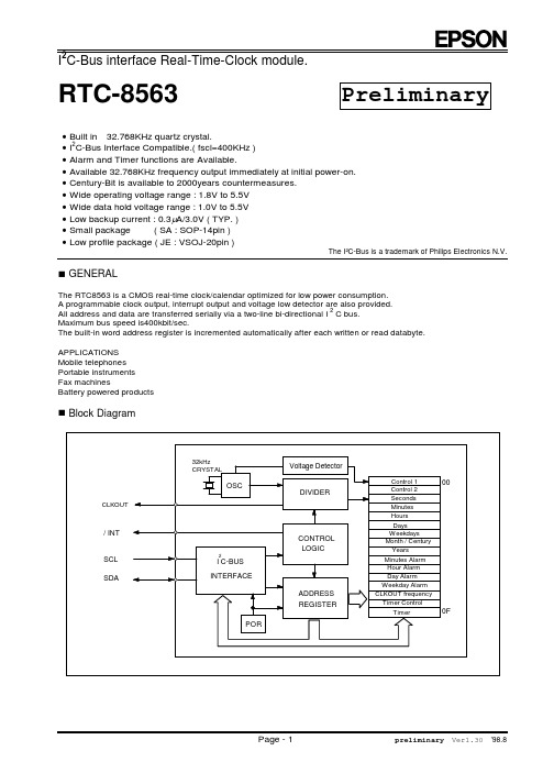
n Block Diagram
CLKOUT / INT SCL SDA
32kHz CRYSTAL
OSC
Voltage Detector DIVIDER
MIN.
TYP.
MAX.
Unit
IDDO
fSCL=400KHz fSCL=100KHz
800
mABiblioteka 200mAIDD fSCL=0Hz, VDD=5.0V
0.35
0.75
mA
fSCL=0Hz, VDD=3.0V
0.30
0.65
mA
fSCL=0Hz, VDD=2.0V
0.25
0.60
mA
IDD32K fSCL=0Hz, VDD=5.0V
bit 4
bit 3
bit 2
bit 1
bit 0
00
Control 1
TEST
0
STOP
0
TEST
0
0
0
01
Control 2
0
0
0
TI / TP
AF
TF
AIE
TIE
02
Seconds
VL
4
2
1
8
4
2
1
03
Minutes
x
4
2
1
8
4
2
1
04
Hours
x
x
2
1
8
SIG SAUER 556xi
2. Pull the rear takedown pin from left to right until stopped by the detent. 7
2
W ADDITIONAL WARNING Early 556xi rifles chambered in 5.56x45mm NATO were fitted with a lighter hammer spring. Using that lower receiver assembly with this kit upgrade in 7.62x39mm, may produce light primer strikes and failures to fire. A hammer spring P/N 1511193 is available for factory installation in your lower to resolve this. Please contact SIG SAUER for further information.
3
TABLE OF CONTENTS
Warnings. . . . . . . . . . . . . . . . . . . . . . . . . . . . . . . . . . . . . . . . . . . . . . . . . . . . . . . . . . . . . 2 General Safety Information. . . . . . . . . . . . . . . . . . . . . . . . . . . . . . . . . . . . . . . . . . . . . . . 3 Caliber Exchange Kit Components. . . . . . . . . . . . . . . . . . . . . . . . . . . . . . . . . . . . . . . . . 5 Conversion Kit Components. . . . . . . . . . . . . . . . . . . . . . . . . . . . . . . . . . . . . . . . . . . . . . 5 Required Tools . . . . . . . . . . . . . . . . . . . . . . . . . . . . . . . . . . . . . . . . . . . . . . . . . . . . . . . 5 1.0 Preparing the 556xi for Installation of the Kit. . . . . . . . . . . . . . . . . . . . . . . . . . . . . . 6 2.0 Barrel Removal. . . . . . . . . . . . . . . . . . . . . . . . . . . . . . . . . . . . . . . . . . . . . . . . . . . . 13 3.0 Barrel Installation . . . . . . . . . . . . . . . . . . . . . . . . . . . . . . . . . . . . . . . . . . . . . . . . . . 16 4.0 Reassembly. . . . . . . . . . . . . . . . . . . . . . . . . . . . . . .. . . . . . 21 5.0 Conduct a Function Check. . . . . . . . . . . . . . . . . . . . . . . . . . . . . . . . . . . . . . . . . . . 28 6.0 Conversion Kit Instructions. . . . . . . . . . . . . . . . . . . . . . . . . . . . . . . . . . . . . . . . . . . 30
TI产品中文版说明书
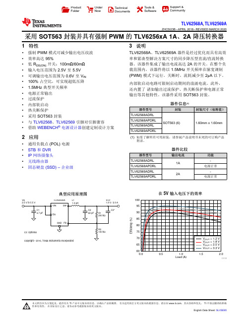
Load (A)E f f i c i e n c y (%)0.00.51.0 1.52.06065707580859095100D008V INV OUTL1TLV62569AProduct Folder Order Now Technical Documents Tools &SoftwareSupport &CommunityTLV62568A ,TLV62569AZHCSI23B –APRIL 2018–REVISED MARCH 2020采用SOT563封装并具有强制PWM 的TLV6256xA 1A 、2A 降压转换器1特性•强制PWM 模式可减少输出电压纹波•效率高达95%•低R DS(ON)开关:100m Ω/60m Ω•输入电压范围为2.5V 至5.5V •可调输出电压范围为0.6V 至V IN •100%占空比,可实现超低压降• 1.5MHz 典型开关频率•电源正常输出•过流保护•内部软启动•热关断保护•采用SOT563封装•与TLV62568、TLV62569引脚对引脚兼容•借助WEBENCH ®电源设计器创建定制设计方案2应用•通用负载点(POL)电源•STB 和DVR •IP 网络摄像头•无线路由器•固态硬盘(SSD)–企业级3说明TLV62568A 、TLV62569A 器件是经过优化而具有高效率和紧凑型解决方案尺寸的同步降压型直流/直流转换器。
该器件集成了输出电流高达2A 的开关。
在整个负载范围内,该器件将以1.5MHz 开关频率在脉宽调制(PWM)模式下运行。
关断时,流耗减少至2μA 以下。
内部软启动电路可限制启动期间的浪涌电流。
此外,还内置了诸如输出过流保护、热关断保护和电源正常输出等其他特性。
该器件采用SOT563封装。
器件信息(1)器件型号封装封装尺寸(标称值)TLV62568ADRL SOT563(6)1.60mm x 1.60mmTLV62568APDRL TLV62569ADRL TLV62569APDRL(1)如需了解所有可用封装,请参阅产品说明书末尾的可订购产品附录。
实验室仪器清单

24030308 21061700 24020402 21060116 21060705 24060119 21030921 24011002 21060501
观片机 离心机 心电图机 电子天平 恒温水箱 血沉架 血红蛋白仪 电动吸引器 干燥箱 氧气钢瓶 吸氧器
Thermo Thermo Thermo Thermo Thermo Thermo Thermo Thermo 东亚 东亚 海尔 海尔 Thermo
Bio-Rad Bio-Rad 英国Shandon公司 英国Shandon公司
24060223 24060223 21060903 21060903 21060903 21060903 21060903 21060903 22170910 22170910
21060602
烘片机 摊片机 CO2培养箱(气套) CO2培养箱(气套) CO2培养箱(水套) CO2培养箱(水套) CO2培养箱(水套) CO2培养箱(水套) 液氮罐 液氮罐 液氮罐 液氮罐 电冰柜 电冰柜 低温冰箱
到科时间 2008/6/11 2008/6/11 2008/6/11 2009/3/11 2008/6/11 2008/6/11 2008/6/11 2008/6/11 2008/6/11 2008/6/11 2008/6/11 2008/6/11
负责人 王煜非 王煜非 王煜非 王煜非 王煜非 王煜非 王煜非 王煜非 王煜非 王煜非 王煜非 王煜非
BX51 BS224S TE412-LE Sonic VCX130 SIVortex5 985370-395EL WTL-10K
仪器序列号 L-803614 L-803637 L-803616 L-606645 L-801072 L-801043 H-801043 H-801001 H-801064 H-801036 H-801015 H-801072
ABB电源电缆接头目录说明书

—C ATALOGPower cable compression lugs Installation of solderless compression lugs on power cables23—Compression power cable lugs solutions4 – 6I ntroduction7 – 20S pec-Kon®lugs21 – 28C olor-Keyed®lugs29 – 34T ools and accessoriesStrands cut Nicked strandsStrip length too short Strip length too long4CO M PR E S S I O N P OW E R C A B LE LU G S C ATA LO GThis method allows electrical workers to make in-stallations with little effort and at a considerablesavings in time. The benefit, of course, is a high-quality connection at a low installed cost.—Compression power cable lugsThe ABB method is betterThe ABB method of installing compression lugs on power cables isdesigned to provide a high degree of reliability in electrical wiring.STEP 2Carefully strip the insulation on de-energizedwires to avoid nicking or cutting conductors.Strip the insulation to the proper length so thatconductors can be fully inserted into the lugbarrel.Just four easy steps to a perfect connection!*STEP 1Determine the proper lug for the cable size beingused. Lugs are marked to show cable size.—* Pictures and expla-nations are based onSpec-Kon® metricproduct range. Tools,dies, lugs and markingsmay differ for eachproduct rangeCable size5STEP 4STEP 3Die CodeMarkingDie Code MarkingSelect the proper installing die and appropriate tool.Locate tool with correct die in proper position on lug and activate tool.When making multiple crimps, make the first crimp nearest the tongue and work towards the barrel end.When properly crimped, the die code number will be embossed on the lug for easy inspection to determine if correct die and lug combination was used.BarrelTongue1e crimp 2e crimpDie location for compressionDie code embossedRefer to the instruction sheet supplied with the lugs for information regarding strip length, die selection and number of compressions required.6CO M PR E S S I O N P OW E R C A B LE LU G S C ATA LO GABB method* dies are designed to produce a circumferential, hex- or diamond-shaped com-pression rather than a simple indent. Precision dies are an integral part of the ABB method. The precision hardened steel dies exert tremendous, controlled pressure on the lug and conductor. The dies compress the lug around the cable, convert-ing the round strands to hexagonal or diamond shapes and forming the strands and lug into a solid mass. Each die is designed so that all con-ductors receive the same amount of compression force.The circumferential compression creates a large area of high-pressure contact between cable and lug which, in turn, assures high conductivity, low resistance, and high pullout values which exceed UL/IEC/CE requirements. These features result in a permanent, low installed cost connection. You can install it, and forget it.—HEX crimping technology Precision dies form a solid homogenous massThe ABB method utilizing compression tools with matching dies forms the lug and conductor into a solid, homogenous mass to provide an optimum electrical bond between lug and conductor.—* Pictures and expla-nations are based on the Spec-Kon® metric product range. Tools, dies, lugs and markings may differ for each product rangeThe ABB system tells you where to place the installing die.Before compression, a typical cross section of cable and lug consists of about 75% metal and 25% air.After air compression by the ABB Method, the cross section looks like this, nearly 100% metal with v irtually no air spaces.Die code embossed7* For other tools compatibility, please contact your ABB local contact or check our website for your local contact numberConductorSpec-Kon ®25—Spec-Kon® lugs Quick guide—Spec-Kon® die selector Quick guide8CO M PR E S S I O N P OW E R C A B LE LU G S C ATA LO G—Spec-Kon ® lugsCopper / Straight – one hole typeApplication • C opper tin plated Metric Compression Lug for power cables for rated voltage up to 36kV. From 6 to 400 mm 2• S pecially designed to accommodate both stranded (class 2) and flexible (class 5) power cables according to IEC 60228Characteristics• S traight - one hole lug with die code marking to assist installation work and inspection• Hole inspection to ease installation control• Chamfer barrel to assist installation work Material • C opper. Comply to EN13600Surface • T in plated Certification• Comply to IEC 61238 - CE declarationCK25602889—Spec-Kon ® lugsCopper / Straight – one hole typeApplication • C opper tin plated Metric Compression Lug for power cables for rated voltage up to 36kV. From 6 to 400 mm 2• S pecially designed to accommodate both stranded (class 2) and flexible (class 5) power cables according to IEC 60228Characteristics• S traight - one hole lug with die code marking to assist installation work and inspection• Hole inspection to ease installation control• Chamfer barrel to assist installation work Material • C opper. Comply to EN13600Surface • T in plated Certification• Comply to IEC 61238 - CE declarationCK2510CO M PR E S S I O N P OW E R C A B LE LU G S C ATA LO G––Spec-Kon ® lugsCopper / 45° – one hole typeApplication • C opper tin plated Metric Compression Lug for power cables for rated voltage up to 36kV. From 6 to 400 mm 2• S pecially designed to accommodate both stranded (class 2) and flexible (class 5) power cables according to IEC 60228Characteristics• 45 degrees - one hole lug with die code marking to assist installation work and inspection• Hole inspection to ease installation control• Chamfer barrel to assist installation work Material • C opper. Comply to EN13600Surface • T in plated Certification• Comply to IEC 61238 - CE declarationCFBIDCK2560288Copper / 45° – one hole typeApplication • C opper tin plated Metric Compression Lug for power cables for rated voltage up to 36kV. From 6 to 400 mm 2• S pecially designed to accommodate both stranded (class 2) and flexible (class 5) power cables according to IEC 60228Characteristics• 45 degrees - one hole lug with die code marking to assist installation work and inspection• Hole inspection to ease installation control• Chamfer barrel to assist installation work Material • C opper. Comply to EN13600Surface • T in plated Certification• Comply to IEC 61238 - CE declarationCFBIDCK25Application • C opper tin plated Metric Compression Lug for power cables for rated voltage up to 36kV. From 6 to 400 mm 2• S pecially designed to accommodate both stranded (class 2) and flexible (class 5) power cables according to IEC 60228Characteristics • 90 degrees - one hole lug with die code marking to assist installation work and inspection• Hole inspection to ease installation control• Chamfer barrel to assist installation work Material • C opper. Comply to EN13600Surface • T in plated Certification• Comply to IEC 61238 - CE declarationCDF BICopper / 90° – one hole typeCK2560288Application • C opper tin plated Metric Compression Lug for power cables for rated voltage up to 36kV. From 6 to 400 mm 2• S pecially designed to accommodate both stranded (class 2) and flexible (class 5) power cables according to IEC 60228Characteristics • 90 degrees - one hole lug with die code marking to assist installation work and inspection• Hole inspection to ease installation control• Chamfer barrel to assist installation work Material • C opper. Comply to EN13600Surface • T in plated Certification• Comply to IEC 61238 - CE declarationCDF BICopper / 90° – one hole typeCK2560288Copper / Straight long barrel – one hole typeApplication • C opper tin plated Metric Compression Lug for power cables for rated voltage up to 36kV. From 6 to 400 mm 2• S pecially designed to accommodate both stranded (class 2) and flexible (class 5) power cables according to IEC 60228Characteristics• S traight long barrel - one hole lug with die code marking to assist installa-tion work and inspection• Hole inspection to ease installation control• Chamfer barrel to assist installation work Material • C opper. Comply to EN13600Surface • T in plated Certification• Comply to IEC 61238 - CE declarationCK2560288Copper / Straight long barrel – one hole typeApplication • C opper tin plated Metric Compression Lug for power cables for rated voltage up to 36kV. From 6 to 400 mm 2• S pecially designed to accommodate both stranded (class 2) and flexible (class 5) power cables according to IEC 60228Characteristics• S traight long barrel - one hole lug with die code marking to assist installa-tion work and inspection• Hole inspection to ease installation control• Chamfer barrel to assist installation work Material • C opper. Comply to EN13600Surface • T in plated Certification• C omply to IEC 61238 - CE declarationCK25Copper / Straight – two hole typeApplication • C opper tin plated Metric Compression Lug for power cables for rated voltage up to 36kV. From 25 to 400 mm 2• S pecially designed to accommodate both stranded (class 2) and flexible (class 5) power cables according to IEC 60228Characteristics• S traight - two hole lug with die code marking to assist installation work and inspection• Hole inspection to ease installation control• Chamfer barrel to assist installation work Material • C opper. Comply to EN13600Surface • T in plated Certification• Comply to IEC 61238 - CE declarationCK25Copper / Straight long barrel – two hole typeApplication • C opper tin plated Metric Compression Lug for power cables for rated voltage up to 36kV. From 25 to 400 mm 2• S pecially designed to accommodate both stranded (class 2) and flexible (class 5) power cables according to IEC 60228Characteristics • S traight long barrel - two hole lug with die code marking to assist installa-tion work and inspection• Hole inspection to ease installation control• Chamfer barrel to assist installation work Material • C opper. Comply to EN13600Surface • T in plated Certification• Comply to IEC 61238 - CE declarationCK2560288Copper / Straight Narrow Tongue – one hole typeApplication • C opper tin plated Metric Compression Lug for Switchers and Breakers with reduced space terminal blocks. From 6 to 300 mm 2• S pecially designed to accommodate both stranded (class 2) and flexible (class 5) power cables according to IEC 60228Characteristics • S traight Narrow Palm - two hole lug with die code marking to assist instal-lation work and inspection• Hole inspection to ease installation control• Chamfer barrel to assist installation work Material • C opper. Comply to EN13600Surface • T in plated Certification• Comply to IEC 61238 - CE declarationCK25—Spec-Kon ® lugsCopper / Straight Narrow Tongue – one hole typeApplication • C opper tin plated Metric Compression Lug for Switchers and Breakers with reduced space terminal blocks. From 6 to 300 mm 2• S pecially designed to accommodate both stranded (class 2) and flexible (class 5) power cables according to IEC 60228Characteristics• S traight Narrow Palm - two hole lug with die code marking to assist instal-lation work and inspection• Hole inspection to ease installation control• Chamfer barrel to assist installation work Material • C opper. Comply to EN13600Surface • T in plated Certification• C omply to IEC 61238 - CE declarationCK25—Spec-Kon ® lugsCopper / Butt splicesApplication • C opper tin plated Metric Compression Butt Splices for power cables for rated voltage up to 36kV. From 6 to 400 mm 2• S pecially designed to accommodate both stranded (class 2) and flexible (class 5) power cables according to IEC 60228Characteristics • D ie code marking to assist installation work and inspection • Hole inspection to ease installation control• Chamfer barrel to assist installation work Material • C opper. Comply to EN13600Surface • T in plated Certification• C omply to IEC 61238 - CE declarationCK25—Color-Keyed® lugsQuick guideCK25—Color-Keyed® die selectorQuick guideConductor SizeColor-Keyed ®[mm 2]LugPart numberH-CK 240B-CK 240H-CK 400B-CK 400—* For other toolscompatibility, please contact your ABB local contact or check our website for your local contact numberCopper / Straight – one hole typeApplication • C opper tin plated Metric Compression Lug for power cables for rated Array voltage up to 36kV. From 6 to 400 mm2• I ntended for electricity distribution or industrial networks in which theyCopper / Straight – one hole typeApplication • C opper tin plated Metric Compression Lug for power cables for ratedvoltage up to 36kV. From 6 to 400 mm2• I ntended for electricity distribution or industrial networks in which theyCopper / 45 degrees – one hole typevoltage up to 36kV. From 6 to 240 mm2• I ntended for electricity distribution or industrial networks in which theycan be subjected to short-circuits of relatively high intensity and duration• S pecially designed to accommodate both stranded (class 2) and flexible(class 5) power cables according to IEC 60228Copper / 90 degrees – one hole typevoltage up to 36kV. From 6 to 240 mm2• I ntended for electricity distribution or industrial networks in which theyCopper/Straight - two hole typeApplication• C opper tin plated Metric Compression Lug for power cables for rated voltage up to 36kV. From 25 to 300 mm 2• I ntended for electricity distribution or industrial networks in which theycan be subjected to short-circuits of relatively high intensity and duration•Specially designed to accommodate both stranded (class 2) and flexible(class 5) power cables according to IEC 60228S traight - two holes lug with Color-Keyed® technology (error-free installation)• Hole inspection to ease installation control • Short Circuit resistance*• Chamfer barrel to assist installation work • Copper. Comply to EN13600• Tin plated • Comply to IEC 61238 - CE declaration—* Six short-circuits are applied after the 200th heat cycle (IEC 61238-1 total of 1000 Heat cycle test). The short-circuit current level shall be such that it raises the bare reference conductors from a temperature of ≤35 °C to a temperature between 250 °C and 270 °CCK25A W GFor other tools compatibility, please contact your ABB local contact or check our website for your local contact number/low-voltage/products/connectivity-groundingCKColor-Keyed® lugsQuick guide AWG copper lugs & splicesA W GCK—Color-Keyed® lugsQuick guide AWG cast copper lugs & splicesColor-Keyed® lugsQuick guide AWG aluminium lugs & splices—Tools and accessoriesHydraulic compression tools – Battery poweredBattery Hydraulic Compression Tool Set Product Ref.: B-CK 400GID Number: 7TCA131530R0002Characteristics- U seable dies: 155 series - C rimping range: 10-400 mm² - Crimping force: 140 kN- Weight: 4.9 kg without battery - Length: 330 mm - S cope of delivery: Tool , 2 batteries Bat-Li34, Charger BatC-230 MC,carrying case with die boxBattery Hydraulic Compression Tool Set Product Ref.: B-CK 240GID Number: 7TCA131530R0001Characteristics- U seable dies: 6 tons series - C rimping range: 6-240 mm² - Crimping force: 52 kN- Weight: 2.3 kg without battery - Length: 455 mm- Scope of delivery: Tool, 2 batteries Bat-Li34, Charger BatC-230, Carrying caseTools and accessoriesCompression tools, dies, pumps and accessoriesThe ABB compression tools with matching dies forms the lug and conductor into a solid, homogenous mass to provide an optimum electrical bond between lug and conductor.—Tools and accessoriesHydraulic compression tools – Hand and remote headManual Hydraulic Compression ToolProduct Ref.: H-CK 240GID Number: 7TCA131530R0014Characteristics- U seable dies: 6 tons series- C rimping range: 6 - 240 mm²- C rimping force: 52 kN- Weight: 2.8 kg- Length: 480 mmManual Hydraulic Compression Too lProduct Ref.: H-CK 400GID Number: 7TCA131530R0000Characteristics- U seable dies: 155 series- C rimping range: 10-400 mm²- Crimping force: 106 kN- Weight: 6.2 kg- Length: 580 mmRemote-Head Hydraulic Compression ToolProduct Ref.: T-CK 240GID Number: 7TCA131530R0003Characteristics- U seable dies: 6 tons series- C rimping range: 6 - 240 mm²- C rimping force: 55 kN- W eight: 1.72 kg- L ength: 260 mm- O perating pressure: 700 barRemote-Head Hydraulic Compression ToolProduct Ref.: T-CK 400GID Number: 7TCA131530R0004Characteristics- U seable dies: 155 series- C rimping range: 10 - 400 mm²- C rimping force: 108 kN- Weight: 3.6 kg- Length: 285 mm31—Tools and accessories Dies and die selector155-series Set die for Metric Compression Lugs Product Ref.: 155xxMCharacteristics- C ompatible with B-CK 400 / H-CK 400 / T- CK 400*- F rom 10 to 400 mm². Comply to IEC 61238- Available for metric Color-Keyed ® and Spec-Kon ®6 ton-series Set die for Metric Compression Lugs Product Ref.: 6tonxxMCharacteristics- C ompatible with B-CK 240 / H-CK 240 / T- CK 240*- F rom 6 to 240 mm². Comply to IEC 61238- Available for metric Color-Keyed ® and Spec-Kon ®* For other tools compatibility, please contact your ABB local contactConductorColor-Keyed ®Spec-Kon ®32CO M PR E S S I O N P OW E R C A B LE LU G S C ATA LO G—Tools and accessoriesHydraulic cutting tools – Battery, hand and remote headBattery Cutting Tool SetProduct Ref.: B-Cut 50GID Number: 7TCA131530R0006Characteristics- C utting capacity: max. 50 mm- C utting force: 25 kN- W eight: 2.1 kg less battery- L ength: 355 mm- A pplication: non-ferrous/ideally suited for cutting fine stranded conductors- F eatures: electronic overload protection and safety control lever- Scope of delivery: Tool, 2 batteries Bat-Li34, Charger BatC-230, Carrying caseHand Cutting Tool SetProduct Ref.: H-Cut 22GID Number: 7TCA131530R0005Characteristics- C utting capacity: max. 22 mm- C utting force: 39 kN- Weight: 2.8 kg- Length: 390 mm- A pplication: steelRemote-Head Cutting Tool SetProduct Ref.: T-Cut 20GID Number: 7TCA131530R0007Characteristics- C utting capacity: max. 40 mm- C utting force: 76 kN- W eight: 4 kg- Length: 340 mm- A pplication: steel- Operating pressure: 700 bar33—Tools and accessoriesHydraulic pumpsMobile Battery Operated Hydraulic Pump SetProduct Ref.: M-Pump 1300GID Number: 7TCA131530R0008Characteristics- O il delivery: 1.300 ml/min (low pressure) 200 ml/ min (high pressure)- O il filling: 600ml (400ml useable)- P rinciple: two parallel working 2-step piston pumps with rapid advance- P ower supply: 14.4 V battery (LiA-34) (useable with one or two batteries)- H ydraulic connection: Coupling Cejn series 115- D imensions (LxWxH): 380 x 205 x 240 mm- W eight: 7.7 kg less battery- W orking pressure 700bar (can be set from 150 - 850 bar by the manufacturer)- F eatures: - wired remote control 5m (included) - rotatable hydraulic coupling- S cope of delivery: - Mobile pump - 2 batteries Bat-Li 34 - 2 charger BatC-230Mobile Battery Operated Hydraulic Pump SetProduct Ref.: F-Pump 400GID Number: 7TCA131530R0009Characteristics- O il delivery: 0.4 l/min- Operating pressure: 700 bar (adjusted)- W eight: 15.7 kg- D imensions (LxWxH): 230 x 230 x 395 mm- O il fill: 1.2 l (0.8 l serviceable)- P ower supply: 230 V~ (370 W)- O peration: one-hand remote control with touch control- H ose coupling: CEJN-coupling series 115- Options: adjustable pump pressure from 150 to 850 bar by manufacturer- I ncluded in delivery: Electrohydraulic Fixed Pump, Quick coupling, Foot switch ( if requested)- T here is no hose included in this item.34CO M PR E S S I O N P OW E R C A B LE LU G S C ATA LO GBattery ChargerProduct Ref.: BatC-230GID Number: 7TCA131530R0011Characteristics- For recharge of BatC-230-P ower supply: 230 V / 50 Hz - Weight: 0.5 kg- Measures (L x W x H): 150 x 85 x 75 mm- Recharge time: LiIon (3,3 Ah) approx. 75 min.- NiCd (2,0 Ah) approx. 45 min.- NiMH (3,0 Ah) approx. 90 minLi-Ion BatteryProduct Ref.: Bat-Li 34GID Number: 7TCA131530R0010Characteristics- T echnology: Lithium Ion - V oltage: 14.4 V - Capacity: 3.3 Ah- Measures (L x W x H): 110 x 70 x130 mm - Weight: 0.56 kg- Charging time: approx. 75 min.- Useable Charger: BatC-230Power Supply for battery tower compression tool Product Ref.: Power-230GID Number: 7TCA131530R0012Characteristics- I nput: 220 - 240 V ca. 50-60 Hz 70 W - 800 W - O utput: 14.4 V - 5-60A - C onnection cable: 5 m - W eight: 0.8 kgHydraulic Hose 3 mProduct Ref.: HydT-3GID Number: 7TCA131530R0013Characteristics- H ose with Oilfill including coupling system (Nipple and coupler)- L ength of hose: 3 m- Working pressure max. 1000 bar- Coupling system Cejn Series 115—Tools and accessories Accessories3571345621 Rail & transportation |2 Power utility & renewable energy |3 Aerospace |4 Food beverage & agriculture |5 Commercial, institutional, residential |6 Automation, OEM, panel builders |7 Chemicals & pharmaceutical, mining & minerals |8 On & offshore, marine78—ABB products are part of your success Designed to perform9A K K 107045A 3839© Copyright 2017 ABB. All rights reserved.Specifications subject to change without notice.—ABB LtdElectrification Products Tower CourtFoleshill Enterprise Park Courtaulds Way Coventry CV6 5NX United KingdomTel: +44 (0) 333 999 9900Fax: +44 (0) 333 999 9901/uk。
- 1、下载文档前请自行甄别文档内容的完整性,平台不提供额外的编辑、内容补充、找答案等附加服务。
- 2、"仅部分预览"的文档,不可在线预览部分如存在完整性等问题,可反馈申请退款(可完整预览的文档不适用该条件!)。
- 3、如文档侵犯您的权益,请联系客服反馈,我们会尽快为您处理(人工客服工作时间:9:00-18:30)。
Conditions Ant-Tx Specification
832 – 862 MHz 832 – 862 MHz 10 – 771 MHz 771 – 791 MHz 791 – 821 MHz 821 – 825 MHz 925 – 960 MHz 1565.420 – 1573.374 MHz 1573.374 – 1577.466 MHz 1577.466 – 1585.420 MHz 1597.5515 – 1605.886 MHz 1664 - 1724 1805 – 1880 MHz 1884.5 – 1919.6 MHz 2110 – 2170 MHz 2400 – 2500 MHz 2500 – 2586 MHz 2586– 2620 2620– 2690 3328– 4310 4992– 6000 832 – 862 MHz 832 – 862 MHz
Data Sheet: Rev D 09/28/2012 © 2012 TriQuint Semiconductor, Inc.
- 1 of 9 -
Disclaimer: Subject to change without notice e Connecting the Digital World to the Global Network
Isolation
Tx Impedance (single-ended) (7) Ant Impedance (single-ended)(7)
Notes: 1. All specifications are based on the TriQuint schematic for the main reference design shown on page 4 2. In production, devices will be tested at room temperature to a guardbanded specification to ensure electrical compliance over temperature 3. Electrical margin has been built into the design to account for the variations due to temperature drift and manufacturing tolerances 4. Typical values are based on average measurements at room temperature 5. Design goal is to meet 3.0 dB Max. Need SPC data to determine actual performance 6. Relative to zero dB 7. This is the optimum impedance in order to achieve the performance shown 8. Target minimum is based on future design revision goals 9. Over any 5 MHz in-band
Tx-Rx Specification
791 – 821 MHz (Differential) 832.5 – 862 MHz (Differential)(8) 791 – 821 MHz (Common-mode) 832.5 – 862 MHz (Common-mode) 1574 – 1577 MHz 1664 – 1724 MHz 2496 – 2586 MHz
Max
3.0 1.5 -
Units
MHz dB dB p-p dB dB dB dB dB dB dB dB dB dB dB dB dB dB dB dB dB dB dB dB dB dB dB dB dB dB dB dB
Absolute Attenuation (6)
Return Loss at Tx Return Loss at Antenna
®
856979
806/847 MHz Duplexer RX – Electrical Specifications (1)
Specified Temperature Range: (2) -20 to +85 ºC
Parameter (3)
Center Frequency Maximum Insertion Loss Amplitude Variation(8)
Notes: 1. All specifications are based on the TriQuint schematic for the main reference design shown on page 4 2. In production, devices will be tested at room temperature to a guardbanded specification to ensure electrical compliance over temperature 3. Electrical margin has been built into the design to account for the variations due to temperature drift and manufacturing tolerances 4. Typical values are based on average measurements at room temperature 5. Relative to zero dB 6. All power levels are referenced to the antenna port. Two CW tones are applied at frequencies f1 and f2, and the resultant intermodulation product in the Rx band is measured. The first tone is applied to the Tx port, in the range f1 = 832 to 862 MHz, at +21.5 dBm (referenced to the antenna port). The second tone is -15 dBm, applied to the antenna port at f2, with the following four cases: a. f2 = 41 MHz b. f2 = 2 * f1 - 41 MHz c. f2 = f1 + 41 MHz d. f2 = 3 * f1 - 41 MHz The intermodulation product is measured at f1 - 41 MHz. 7. This is the optimum impedance in order to achieve the performance shown 8. Over any 5 MHz in-band
®
856979
806/847 MHz Duplexer TX – Electrical Specifications (1)
Specified Temperature Range: (2) -20 to +85 ºC
Parameter (3)
Center Frequency Maximum Insertion Loss (5) Amplitude Variation(9)
Absolute Attenuation (5)
Return Loss at Rx Return Loss at Antenna Output phase balance Output amplitude balance(8) IM2 product (6) (a,b) IM3 product (6) (c,d) ANT Impedance (single-ended ) (7) Rx Impedance (balanced) (7)
Functional Block Diagram
Top View
Gnd
7
Ant
6
Gnd
5 4
Rx Out Rx Out
8 1 2
Gnd
3
Gnd
Tx in
General Description
856979 is a high-performance Temperature Compensated Surface Acoustic Wave (TC SAW) duplexer designed to meet the strict LTE requirements for use in Band 20. The 856979 is specifically designed to meet the high performance expectations of insertion loss, isolation and linearity in LTE systems operating in Band 20 applications under all operating conditions. The use of TC SAW technology enables stable performance over the entire temperature range.
Conditions Ant-Rx Specification
791–821 MHz 791–821 MHz 10 – 760 MHz 760 – 770 MHz 832 – 862 MHz 862 – 890 MHz 890 – 910 MHz 910 – 2500 MHz 2500 – 6000 MHz 791–821 MHz 791–821 MHz 791–821 MHz 791–821 MHz