2014-2015数字逻辑试卷
数字逻辑与设计试卷

《数字逻辑与设计》考试试卷试卷2B一、填空题(本大题共7道小题,每空1分,共15分) 1.数制转换:(A3)16=( )8 , (100.25)10=( )2 , (1000)自然二进制码=( )余3码 ,(110100)2=( )BCD 。
2.[X] 补=10110,则[X]反= ,[X]原= 。
3.数字逻辑电路分为两大类 。
4.逻辑函数)(D A C B A F ++⋅= 的对偶函数='F ,反函数=F 。
5.信号经不同路径到达会合点有先有后称为 ,产生错误输出的现象称为 。
6.三态门中的“三态”是指 、 和 。
7.组合逻辑电路在任一时刻的输出只和当时的输入有关,与电路 状态无关。
二、单项选择题(每小题2分,共8分)1.下列各式中的四变量A 、B 、C 、D 的最小项是( )。
A. ABCDB. )(D C AB + C .D C B A +++ D.D C B A +++2. 若左移寄存器输入端为0,则其在2个CP 脉冲作用下,可实现所存数据( )。
A 乘以2B 乘以4C 除以2D 除以43. 属于组合逻辑电路的是( )。
A 触发器B 数据选择器C 移位寄存器D 计数器4.函数BC B A F +=的“或与”式为( )。
A.))((C B C A ++B. ))((C A B A ++C. C)B B)((A ++D. B)C)(A (B ++三、逻辑函数化简题(共15分,每小题5分)1.用公式法化简逻辑函数D++⋅=为最简与或表达式。
F⋅⋅+⋅BAACCBA2.用卡诺图化简逻辑函数DAF+B+=为最简与或表达式。
C+DBCBAABCD3.用卡诺图化简函数∑(m,DCABF为最简与或表达式,其中无,,15=)13,7,2,0)(,关最小项为∑)(d。
1,,8,6,5,4,310四、分析题(共20分,第1题8分,第2题12分):(1)完成该逻辑电路真值表;(2)说明该电路的逻辑功能。
2015数字逻辑期末模考试题
长沙理工大学期末模拟考试题2014 — 2015 学年第二学期一、填空题(26分,每空2分)1. (2015)D =()B = ()H = ()8421BCD2. 仓库门上装了两把暗锁,A、B两位保管员各管一把锁的钥匙,必须二人同时开锁才能进库。
这种逻辑关系为。
3. 逻辑函数式F=AB+CD的对偶式为,最小项表达式为∑F( )。
=m2.逻辑函数D''+'+=的最简与或式++''+F'ACDACABCDABDABCC是。
4. 从结构上看,时序逻辑电路的基本单元是。
5.多个集电极开路门(OC门)的输出端可以 ____________。
6.T触发器的特性方程是________,当T=1时,特性方程为________,这时触发器可以用来作______分频器。
7.时序电路中对于自启动能力的描述是______二、选择题(20分,每题2分)1. 计算机键盘上有101个键,若用二进制代码进行编码,至少应为()位。
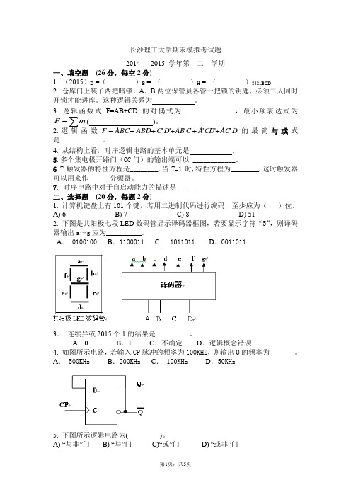
A) 6 B) 7 C) 8 D) 512. 下图是共阳极七段LED数码管显示译码器框图,若要显示字符“5”,则译码器输出a~g应为__________。
A. 0100100 B.1100011 C. 1011011 D.00110113.连续异或2015个1的结果是____ _____。
A.0B.1 C.不确定D.逻辑概念错误4. 如图所示电路,若输入CP脉冲的频率为100KHZ,则输出Q的频率为_______。
A. 500KHz B.200KHz C. 100KHz D.50KHz5. 下图所示逻辑电路为( )。
A) “与非”门B) “与”门C)“或”门D) “或非”门6. 在下列逻辑部件中,属于组合逻辑电路的是( )。
A) 计数器 B) 数据选择器 C) 寄存器 D) 触发器7. 已知某触发器的时钟CP ,异步置0端为R D ,异步置1端为S D ,控制输入端V i 和输出Q 的波形如图所示,根据波形可判断这个触发器是( )。
2014年《数字逻辑设计与应用》半期试卷

电子科技大学2013-2014学年第二学期“数字逻辑设计及应用”课程考试题(半期)(120分钟)考试日期 2014年 月 日I. To fill the answers in the “( )” ( 2’ X 15 = 30 )1. Given ∑=ABCF )5,4,1(, then ABC F ∏=( 0,2,3,6,7 ),F =A ’∑BC( 1 )+A∑BC( 0,1 ).2. ( 1001 0011 )8421BCD =( 1111 0011 )2421BCD .3. ( 0101 1101 )2=( 0111 0011 )Gray .4. Open-drain output has two states without if there is no pull up resistor: Low and ( Hi-Z ).5. A two’s -complement =0110 1010, C one ’s -complement =1111 1011, [A-C]two’s -complement =( 0110 1110 ). Is it overflow for [A-C]two’s -complement ? (Yes or No) [ No ]6. XOR gate in positive logic level is equivalent to ( XNOR ) gate in negative logic level.7. Five variables can make ( 32 ) minterms. The sum of all the minterms must be ( 1 ).8. If the function ∑=ABCF )6,3,2,1(, then ∑=ABC F '( 0, 4, 5, 7 ).9. If the information bits are 1001 0010, the check bit is ( 0 ) for odd-parity. 10. To make 2014 code-words, ( 11 ) bits should be used at least.11. Given the circuit shown in Figure 1, its output expression F=( (b(a+c)+ac)’ ).Figure 1II. There is only one correct answer in the following questions.( 3’ X 10=30 )1. Which of the following codes has the self-complement property? ( D)A. GrayB. BiquinaryC. 8421BCDD. Excess-32. Which of the following 2-input gates can form a complete set of logic gates? ( B )A. ORB. NORC. XORD. XNOR(或非门构成逻辑门完全集的示意图)3. Which of the following gates is equivalent to XNOR? ( A)A. B. C. D.4. Which of the following connection is correct? ( C)A. B. C. D.5. Which of the following expressions has no hazard? ( B)A. F=W•Y+W’•Z’+X•Y’•ZB. F=W•Y+W’•Z’+Y•Z’C. F=W•Y+W’•Z’+X•Y’•Z+Y•Z’D. F=W•Y+W’•Z’+X•Y’•Z+W’•X•Y’6. Which of the following statements is correct? ( D)A. The duality of the minimal sum expression is its minimal product.B. The minimum sum-of-product expression has no static-1 hazard.C. The canonical sum must have hazard.D. The minimum sum-of-product expression has no static-0 hazard. 7. The minimum sum of product for AB+A ’C+BCDEFGH is ( A ).A. A •B+A ’•CB. A ’•B+A •CC. A •B+A ’•C+B •CD. A •B+A ’•C+B •C8. Given A=(0011 1111 . 0100)2, its equivalent values for A 10 and A 16 are ( B ) A. (96.58)10, (60.94)16 B. (63.25)10, (3F.4)16C. (96.58)10, (60.49)16D. (63.25)10, (3F.94)169. Given the timing diagram as shown in Figure 2, the output function is ( A ). A. ∑=xyzf )7,6,5,3( B. ∑=xyz f )4,2,1,0( C. ∑=xyz f )6,2,1,0( D. ∑=xyz f )7,2,1,0(Figure 210. A self-dual logic function is a function such that F=F D . Which of the following functions is self-dual? ( C )A. ∑=xyzF )7,5,2,1( B. F=X ’•Y •Z ’+X •Y ’•Z ’+X ’•ZC. F=X •Y+X •Z+Y •ZD. )4,3,0(xyz F ∏=III. Combinational Circuit Analysis And Design: [40’]1.Given F(A,B,C,D)= (B⊕C⊙(B•C))+A’•D•(B•C)’, the “Don’t Care”input combinations is=∑. Simplify the logic function F(A,B,C,D) into the F(A,B,C,D)d(10,11,12,13,14,15)minimal sum using Karnaugh map, and write out NAND-NAND logic expression of the minimal sum. (8’)参考评分标准:1.填写F的卡诺图正确4分,d占1分,错一格扣0.5分,扣完为止;2.化简的表达式正确3分,错一个乘积项扣1分;F minimal-sum (A,B,C,D)=B/C/+B/D+C/D3.“与非-与非“表达式正确1分F NAND-NAND (A,B,C,D)= [(B/C/)/(B/D)/(C/D)/]/2. A combinational circuit is shown as below. (8’)(1) Write out the sum-of-product expression of output F(W,X,Y,Z) for the circuit.(2) Analysis all conditions that the static hazard may exit for the circuit, and indicate types of static hazard.(3)Write out the minimal sum of output F(W,X,Y,Z) for the hazard-free.参考评分标准:1. 原始的积之和表达式正确3分 ,只要是积之和形式就算对,不管是否为原始积之和,错一个(多一个或少一个)乘积项扣一分,扣完为止;F(W,X,Y,Z)=WX/Y/+XY/Z+XY2.指出所有静态冒险存在的条件2分,指出静态冒险类型1分。
数字逻辑复习题 Microsoft Word 文档

本科试卷(一)一、选择题(每小题1分,共15分)1.八进制数8(375.236)的十六制数是________。
A.16(7.4)D F B.16(7.4)D E C. 16(7.4)C F D. 16(7.3)D F2.下列逻辑函数中,与(A+B )(A+C)等价的是_____。
A. F=AB B.F=A+B C. A+BC D. F= B+C3.函数F 的卡诺图如图1-1,其最简与或表达式是_____。
A. D B A D B A F +=D C A +B. D B A D C A C B A F ++=C. D C A D B A C B A F ++=D. D B A D B A D B A F ++=4.4:10线译码器,输入信号端有_____个。
A. 10 B. 2 C. 3 D.45.用四选一数据选择器实现函数Y =0101A A A A +,应使______。
A.D 0=D 2=0,D 1=D 3=1 B.D 0=D 2=1,D 1=D 3=0C.D 0=D 1=0,D 2=D 3=1D.D 0=D 1=1,D 2=D 3=06. 图1-2所示的组合逻辑电路,其函数表达式为______。
A . F AB BD CD =++B .(0,4,5,7,8,12,13,14,15)F m =∑ C . (1,2,3,6,9,,10,11)F m =∑ D .(0,8,12,14,15)F m =∑ ABBDC---D-- 图1-2 图1-37.时序电路中不可缺少的部分为_______。
A. 组合电路 B. 记忆电路 C. 同步时钟信号 D. 组合电路和记忆电路8.与非门构成的基本RS 触发器如图1-3 所示,欲使该触发器保持现态,即1n n Q Q +=,则输入信号应为_____。
A .S=R=0B .S=R=1C .S=1,R=0D .S=0,R=19.n 个触发器构成的计数器中,有效状态最多有____个。
《数字逻辑》期末考试A卷参考答案

《数字逻辑》期末考试 A 卷参考答案
一、判断题:下面描述正确的打‘√’,错误的打‘×’ (每小题1 分,共 10 分)
1、为了表示 104 个信息,需 7位二进制编码 [√ ]
2、 BCD码能表示0 至 15 之间的任意整数[× ]
3、余 3码是有权码[× ]
4、 2421 码是无权码 [ × ]
5、二值数字逻辑中变量只能取值0 和 1,且表示数的大小 [ × ]
6、计算机主机与鼠标是并行通信[× ]
7、计算机主机与键盘是串行通信[√ ]
8、占空比等于脉冲宽度除于周期[√ ]
9、上升时间和下降时间越长,器件速度越慢
10、卡诺图可用来化简任意个变量的逻辑表达式[√]
[×]
二、写出图中电路的逻辑函数表达式。
(每小题 5 分,共10 分)
1、 F=A B
2、 F=AB CD
三、选择题:(多选题,多选或少选不得分,每小题 2 分,共 20 分)。
数字逻辑考试题

二、选择(5分)
1. 的反函数为 =( )。
A. B.
C. D.
2.下列哪个元件是CMOS器件( )。
A. 74S00B. 74LS00C. 74HC00D. 74H00
3.十进制数25用8421BCD码表示为()。
A.10101 B.0010 0101 C.100101 D.10101
5.数字电路按照是否有记忆功能通常可分为两类:、。
A.变量译码器B.加法器C.数码寄存器D.数据选择器
6.GAL是指( )。
A.专用集成电路B.可编程阵列逻辑
C.通用集成电路D.通用阵列逻辑
7.RAM与ROM二者不同的是( )。
A.存储容量B.输出位数C.读操作D.写操作
8.子程序的重载不包括以下( )类型的重载。
A.参数类型的重载B.参数目的的重载
11.AB+ C+ C的最简与或表达式为。=AB+( + )C=AB+ C=AB+C
12.对于共阴极显示器,可以用输出的七段译码器7448来进行译码驱动。
13.将特定的信息表示成二进制代码的过程称为。
二、选择题(每题1分,共10分)
1.下列各门电路中,( )的输出端可直接相连,实现线与。
A.一般TTL与非门B.集电极开路TTL与非门
A. 01B. 11C. 00 D. 10
5.余3码10001000对应的2421码为( )。
A. 01010101B. 10000101
C. 10111011D. 11101011
6.RAM与ROM二者不同的是( )。
A.存储容量B.输出位数C.读操作D.写操作
数字逻辑设计考试试题

数字逻辑设计考试试题1. 引言数字逻辑设计考试试题是在数字电路设计领域中非常重要的一个方面。
它测试了学生对数字逻辑电路和设计原理的理解和应用能力。
本文将讨论几个常见的数字逻辑设计考试试题,并详细解答每一个试题。
2. 试题一 - 逻辑门电路设计试题描述:设计一个4位二进制加法器,使用逻辑门电路实现。
给定两个4位的二进制数字A和B,计算这两个数字的和,并输出一个4位的二进制结果。
解答:首先,我们需要确定所需的逻辑门类型来构建4位二进制加法器。
常用的逻辑门包括AND门、OR门、NOT门和XOR门。
通过逻辑门的组合,我们可以实现加法器的功能。
我们可以将4位二进制加法器分成四个阶段:全加器、加法器主体、进位检测器和结果输出。
在全加器阶段,我们使用XOR门和AND门来计算每一位的和以及进位。
在加法器主体阶段,我们使用多个全加器来实现4位的加法。
在进位检测器阶段,我们使用OR门来检测是否存在进位。
最后,在结果输出阶段,我们将每一位的和输出到相应的输出端口。
通过以上的设计,我们成功地实现了一个4位二进制加法器。
3. 试题二 - 状态机设计试题描述:设计一个简单的状态机,它包含两个状态S0和S1,并包括两个输入信号A和B。
当输入信号A为1时,状态机从S0转换到S1;当输入信号B为1时,状态机从S1转换到S0。
设计状态机的状态转换图和状态转换表。
解答:为了设计该状态机,我们需要确定两个状态之间的状态转换以及输入信号对状态的影响。
状态转换图如下所示:A=1 B=1----------> S1 ----------> S0| || A=0 | B=0| |---------- S0 <---------- S1状态转换表如下所示:当前状态输入A 输入B 下一状态S0 1 0 S1S0 0 0 S0S1 1 0 S0S1 0 1 S0通过上述状态转换图和状态转换表,我们设计并实现了一个简单的状态机。
4. 试题三 - 时序逻辑电路设计试题描述:设计一个4位计数器,它每秒钟自动加1,从0000计数到1111,然后从0000重新开始计数。
数字逻辑考题及答案
数字逻辑试题1答案一、填空:(每空1分,共20分) 1、(20.57)8 =( 10.BC )16 2、(63.25) 10= ( 111111.01 )2 3、(FF )16= ( 255 )104、[X]原=1.1101,真值X= -0.1101,[X]补 = 1.0011。
5、[X]反=0.1111,[X]补= 0.1111。
6、-9/16的补码为1.0111,反码为1.0110 。
7、已知葛莱码1000,其二进制码为1111, 已知十进制数为92,余三码为1100 01018、时序逻辑电路的输出不仅取决于当时的输入,还取决于电路的状态 。
9、逻辑代数的基本运算有三种,它们是_与_ 、_或__、_非_ 。
10、1⊕⊕=B A F ,其最小项之和形式为_ 。
AB B A F += 11、RS 触发器的状态方程为_n n Q R S Q +=+1_,约束条件为0=SR 。
12、已知B A F ⊕=1、B A B A F +=2,则两式之间的逻辑关系相等。
13、将触发器的CP 时钟端不连接在一起的时序逻辑电路称之为_异_步时序逻辑电路 。
二、简答题(20分)1、列出设计同步时序逻辑电路的步骤。
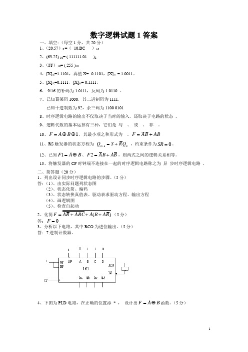
(5分) 答:(1)、由实际问题列状态图 (2)、状态化简、编码 (3)、状态转换真值表、驱动表求驱动方程、输出方程 (4)、画逻辑图 (5)、检查自起动2、化简)(B A B A ABC B A F +++=(5分) 答:0=F3、分析以下电路,其中RCO 为进位输出。
(5分) 答:7进制计数器。
4、下图为PLD 电路,在正确的位置添 * , 设计出B A F ⊕=函数。
(5分)5分 注:答案之一。
三、分析题(30分)1、分析以下电路,说明电路功能。
(10分)解: ∑∑==)7,4,2,1()7,6,5,3(m Y m X 2分A B Ci X Y 0 0 0 0 0 0110 1 0 0 1 0 1 1 1 0 1 0 0 0 1 1 0 1 1 0 1 1 0 1 0 1 1 1 1 1该组合逻辑电路是全加器。
- 1、下载文档前请自行甄别文档内容的完整性,平台不提供额外的编辑、内容补充、找答案等附加服务。
- 2、"仅部分预览"的文档,不可在线预览部分如存在完整性等问题,可反馈申请退款(可完整预览的文档不适用该条件!)。
- 3、如文档侵犯您的权益,请联系客服反馈,我们会尽快为您处理(人工客服工作时间:9:00-18:30)。
数字电路与逻辑设计期末考试样题一、TO FILL YOUR ANSWERS IN THE “( )”(1’ X 5)1. An unused CMOS NAND gate input should be tied to logic ( ) or another input.2. DAC can proportionally convert ( ) input to analog signal output.512 3. A truth table for a ( ) input, 4-output combinational logic function could be stored in a 4 EPROM.4. The RCO output of 74X163 is asserted if and only if the enable signal ( )is asserted and the counter is in state ‘1111’.5. If the signed-magnitude representation is(001101)2 for one number, then it’s 8-bit two’s complement representation is()2.二、Single selection problems: there is only one correct answer in the following questions.(2’ X 5)1、An 8-output demultiplexer has ( ) select inputs.A. 2B. 3C. 4D. 52、For a logical function ,which representation as follows is one and only(唯一). ( )A. logic expressionB. logic diagramC. truth tableD. timing diagram3、In general, to complete the same function, compared to a MOORE machine, the MEAL Y machine has ()。
A. more statesB. fewer statesC. more flip-flopsD. fewer flip-flops4、To design a “1000001” serial sequence generator by shift registers, at least needs a ( ) bit shift register.A. 2B. 3C. 4D.55、The following logic expressions is equal, and the hazard-free one is ( ).A. F=B’C’+AC+A’BB. F=A’C’+BC+AB’C. F=A’C’+BC+AB’+A’BD. F=B’C’+AC+A’B+BC+AB’+A’C’三. Combinational Circuit Analysis: [10]1.Find the minimal product-of-sums expression for BC BC A AB F ++=''. [4]2.Write the minterm list expression for F=W+XZ+XY . [3]F=ΣWXYZ ( )3.Complete the timing diagram of the circuit below. (Assume that the propagation delay of each gate is one Δ) [3]四.Show how to build the following logic function using one 74X138 3-8 binary decoder and some NAND gates.F = A’BD’ + A’CD’ + BCD’Write the truth table and draw the logic diagram. The logic symbol of 74X138 3-to-8 decoder is shown as follows.[10]五. A 2-bit comparator circuit receives two 2-bit numbers, P (P=PP0) and Q (Q=Q1Q0). Design a circuit that the1output F P>Q is 1 if and only if P>Q. Please write the truth table for the circuit. [5]Truth table (真值表)F P>Q六. Clocked Synchronous State Machine Design [ 20 total ]1. Design a clocked synchronous state machine with the state/output table shown below, using D flip-flops. Use two state variables,Q1 Q2, with the state assignment shown as follows. Write transition/output table and excitation/output table. [7]state/output table : state assignment :S X 0 1 A B ,0 D ,1 B C ,0 A ,0 C D ,0 B ,0 D A ,1 C ,0S*,Z2. An excitation/output table of a clocked synchronous state machine using D flip-flops is shown as follows. Write the excitation equations and output equation. [8]3. The excitation equations and output equitation of a clocked synchronous state machine is shown as follows. Draw the logic diagram using positive-edge-triggered (上升沿触发) J-K flip-flops . [5]excitation equations : J 0=( A ⊕Q 1 )’ ; K 0=( A Q 1)’J1= A ⊕Q 0 ; K 1=(A ’Q 0)’output equitation : Y=((AQ 1)’(A ’Q 0))’S Q1 Q2 A 0 0 B 0 1 C 1 0 D 1 1七.Clocked Synchronous State Machine Analysis [ 15 total ]1.Analyze the circuit shown below, write the excitation equations, output equation, transition equations and construct a transition/output table. [8]2. The transition equations and output equitation of a clocked synchronous state machine is shown as follows. Complete the timing diagram for Y, assuming that the machine starts in state Q1,Q0=00. [7]transition equations:Q0*=Q0A’+Q0’AQ1*=Q1A’+Q1’Q0A+Q1Q0’Aoutput equitation: Y=Q1Q0A八.74X163 is a synchronous 4-bit binary counter with synchronous load and synchronous clear inputs. Design a modulo-14 counter, using one 74X163 and some necessary gates, with the following counting sequence: 1, 2, 3, 4, 5, 6, 7, 8, 9, 10, 11, 12, 13, 15, 1, 2, …. Complete the design and draw a logic diagram. [10]Function table for a 74X163Inputs Current State Next state OutputCLR_L LD_L ENT ENP QD QC QB QA QD* QC* QB* QA* RCO0 X X X X X X X 0 0 0 0 01 0 X X X X X X D C B A 01 1 0 X X X X X QD QC QB QA 01 1 X 0 X X X X QD QC QB QA 01 1 1 1 0 0 0 0 0 0 0 1 01 1 1 1 0 0 0 1 0 0 1 0 01 1 1 1 0 0 1 0 0 0 1 1 01 1 1 1 0 0 1 1 0 1 0 0 01 1 1 1 ............. .. 01 1 1 1 1 1 1 1 0 0 0 0 1九. Analyze the circuit showed below, which contains a 74X194 4-bit shift register and a 74151 MSI multiplexer. [15]1. Write the logic expression of feedback function F.2. Write the sequence of states for the 74X194 in this circuit,3. Write the transition/output table of the circuit.(the output is Y and Z)The function table for 74X194 4-bit universal shift register is showed below,Function table for 74194:inputs Next statefunction S1S0 QA* QB* QC* QD*Hold 0 0 QA QB QC QDShift right 0 1 SRSI QA QB QCShift left 1 0 QB QC QD SLSIload 1 1 A B C D。