UGFreeFormFeature解析
UG_NX_modeling_4form_feature

5.1 相对定位 Relative Positioning
5.2 凸台 Boss
5.3 凸垫 Pad
Fmf_boss.prt
fmf_pad_rectangular.prt
5.4 孔 Hole
Fmf_hole_simple.prt
5.5 腔 Pocket
fmf_pocket_rectangular.prt
在任意表面上安放任意外形凹腔
通用凸垫与凹腔
允许选择多个面为en_pad.prt
通用凸垫与凹腔
Insert Form Feature Pad General Insert Form Feature Pocket General __ 允许建立开口的凸垫与凹腔。
五、成形特征 Form Features
Modeling
五、成形特征 Form Features
__假定在部件文件中已存在一个实体 . 1. 考虑定位到其上的可选择对象(体边缘、参考特征等,如果需要首先建立它们 )
2. 选择成形特征的型
3. 选择安放表面(一般要求选择平表面,General Pocket、General Pad除外) 4. 如果需要为孔和键槽选择通过表面(可以使用基准面 ) 5. 选择水平或垂直参考方向(对键槽,矩形腔 /矩形凸垫) 6. 加入尺寸和 /或角度(实数,代数短语,表达式名 )
5.6 键槽 Slot
fmf_slot_rectangular.prt
5.7 沟槽 Groove
矩形
球形
U形
fmf_groove.prt
5.8 编缉 : Edit → Features→ Parameters
通用凸垫 General Pad
在任意表面上安放任意外形凸垫
FreeForm分模功能详细说明FreeFormModelinglus软件教程
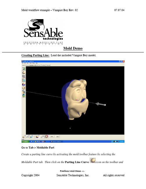
Mold DemoCreating Parting Line: Load the included Vampire Boy model.Go to Tab > Moldable PartCreate a parting line curve by activating the mold toolbar feature by selecting theMoldable Part tab. Then click on the Parting Line Curve icon on the toolbar andFreeform Mold Demo -1-click on the Show Parting Line Color icon to show the parting line. The arrow on the screen indicates the mold pull direction. You can change the direction by clicking onthe Set Direction icon to check the best parting line solution. Once everything is set, click on Apply to create the parting line curve.The parting line curve direction is already set for this model, but be sure the parting line draft angle is set to zero. To check if the draft angle is set to zero for this evaluation, go to Tools > Option > Parting line draft angle. For using the Parting Line tool, always set the draft to zero so that you will get a clear blue line. If the draft is not set to zero, the parting line curve will not be created in the correct location.Currently, the mold pull direction is already set correctly. If you want to show people the different pull direction, click on the Set Direction icon to change the setting.Showing Curvature PlotFreeform Mold Demo -2-The parting line curve is very dense and trying to pick up all the details necessary. If you want to look at the level of quality of the parting line curve, you can turn on the curvature plot and create a curvature plot of each curve. Go to:View > Design Curves -> Create Curvature Plots. Then click on the parting line curves on the model. By default, the plot is set in 2D to show the noise in Z direction only; you can also set to show the noise in X and Y direction by changing the 2D Curvature icon to 3D Curvature icon on the Dynabar. [as shown below]2D curvature plot showing on noise in Z directionFreeform Mold Demo -3-3D curvature plot showing noise in X and Y directionIn most cases, you will only want to use the 2D curvature plot in the Z direction. The number shown on the curvature plot indicates the minimum radius curvature of the curve. This number can be used to determine the tool size for machining in the future. To find the tool radius, simply take the inverse of the curvature value. The equation used in this calculation is shown below:C = 1/R ; C = curvature, R = radiusEditing Parting Line CurveFreeform Mold Demo -4-machining. To avoid this problem, I am going to smooth the parting line curve. Tosmooth the parting line curve, click on the Select icon on the toolbar and then clickon the parting line curve. Change the number on the Points box to reduce thenumber of points on the curve. In most cases, you can reduce the number of point by halfthen refit it. Be aware that it may have drifted from sharp details in the XY plane.Usually, after reducing the points on the parting line, the parting line will likely still be very close to the original parting line. However it does not work for every case. In most situations, you can just reduce the points and refit it just for demo purposes.Now I will refit the parting line curve by clicking on the Fit CurveFreeform Mold Demo -5-to Clay tool under the same flyout as the Parting Line Curve tool. Then click on the parting line curve. Refitting the curve will remove the curvature plot information because the refitted curve is actually a new curve. Therefore, you have to put the curvature plot back on to see the new result. Now you can see that the refitted curves have a low curvature and noise.You can also use the Smooth Curve tool under the Parting Line Curve tool to smooth out the curves. After you are satisfied with the result, you can turn off the curvature plot.Fixing DraftFor this model, there is a draft problem. To demonstrate the draft-fixing feature, youFreeform Mold Demo -6-should point out some draft problems on the model. Indicate the areas behind the nose and the teeth (Create Parting Line actually surrounded these areas with curves, which can be deleted at this time.)The next thing to do is to fix draft. As you can see on the screen, the nose and the tooth have a draft issue. To correct the problem, I can either add material or remove material to correct the problem under the Draft option.Go back to create moldable part and then select Draft tool on the toolbar. Then click on the parting line. The problem areas are shown in blue. Now I want to add material behind the nose to the fix the draft instead of chopping off the nose to fix the draft. So I click on the Add Clay , but hold to the parting line by clicking thePreserver Parting line icon then click Apply.The changes on the model should be very quick, so you can say a few words or gesturing with your hands, then the changes should be done. The fixed model is shown below.Freeform Mold Demo -7-Shelling The ModelClick on the “d” key to show the model in See Through mode, and indicate that it is a solid model. Click the “d” key once more to return to an opaque view.Now you can shell the model. Click on Shell on the toolbar. For this model, I want a 4mm shell. Then change the number in the Shell Thickness box on the dynabarto 4 and click Apply.Freeform Mold Demo -8-The shelling process should be done very quickly. While waiting for the model to be shelled, you can talk about the benefit of this feature. After the shell is complete, click on “d” on the keyboard again to activate the dotted mode for showing the part thickness.Click “d” to change to dotted mode to show part thicknessYou can check the part thickness by using the ruler feature. Go to Tools > Ruler or click“r” on the keyboard to activate the ruler feature. Then select Measure Thicknessicon on the Dynabar and measure the part thickness.Freeform Mold Demo -9-Creating Split JointFor better visual, turn off the clay by clicking on Blank Clay icon. The resulting screen is shown above. By turning off the clay, you can see the glue joint that you will create on the screen.Now I want to be able to create the shiplap joint. I go down to the Split Joint tool and pick on the curve on the screen. It will create a butt joint by default first (shown below) then I will create a shiplap joint on the modelFreeform Mold Demo -10-.After selecting the curve on the screen, a butt joint will be created. The creation of butt joint will not fail on this model. The shiplap joint properties box will pop up automatically when the butt joint is created.On the ShipLap Joint Properties box, set the values on the boxes to:-Offset value to 2mm because it’s a 4mm shiplap-Depth value to 2.5mm, just high enough that people can see the difference -Angle value to 5 degree so that it looks like in a angleFreeform Mold Demo -11-Ensure the Modify Region icon is selected on the dynabar then click on any two points on the outside curve of the model to define the region of the joint then click on any place on the curve within the region to create the split joint (as shown above).For the demo, create shiplap joint at only one place because for every place you do, you have to be able to select the inside curve of the split joint in the middle of the demo when you are doing Make Part and Make Insert. Therefore, to shorten the demo time and keep the audience’s attention, avoid creating more than one split joint.Next you want to show the Groove split joint feature, make an undo after the shiplap joint is created. Then select Groove Joint icon and the Groove Joint Properties box will appear.Freeform Mold Demo -12-Make sure the sum of the Offset value and the Width value does not exceed the width of the split joint, which is 4mm in this case. Otherwise, you will receive an error message. Once the values are entered, ensure the Create Split Joint icon is selected on the dynabar to create a groove joint on the entire curve. Then select the curve on the screen and a Groove Joint will be created (shown as below)Creating the groove joint for the demo is easier for the Make Part step later in the demo because you don’t have to pick the separate section all the way around the curve.Freeform Mold Demo -13-Freeform Mold Demo -14-Making PartNow I will separate the model into 2 parts, part 1 and part 2. I go to the Make Particon on the toolbar. Then select the Split Curve icon on the dynabar and click on the first split joint then the second split joint of the part. Next I click on the Part 1 Sideicon and click on the outside of the model(the face in this example) to select what is going to the part 1.When selecting the part 1 side, uncheck the Blank Clay to show the whole piece of clay. It’s easier in this way.Freeform Mold Demo -15-The first split joint is the outside curve of the part and the second split joint is the inside curve of the partThe first split joint is highlighted inFreeform Mold Demo -16-The second split joint is highlighted in green as shown on the rightnow look at the other part by selecting Work on Part of the other part in the Object List.Freeform Mold Demo -17-To turn on the object list, either click “o” on the keyboard or go to View > Object listOn the Object List, click on the part icon, and select Work On Part option to select the part that you want to work on.For the rest of the demo, we will work on one part of the model, Part 1 the face, though the other Part 2 can be done in a similar way.Freeform Mold Demo -18-Creating Mold InsertSo the next thing I will create an extent for the part, that is defining the actual mold insert dimensions, and create parting surfaces for the model.The extents can be resized to any dimension you need to fit into the mold. To resize it, you go to the set extents option (which is usually active when first entering the Mold Insert tab) and enter the XYZ values for the extents.To resize the extent, click on Create Mold Insert tab on the top of the workspace thenselect Mold Insert Properties and click on Set Extents icon on the Dynabar. Enter the desired dimension for the extent on the X,Y,Z boxes. For the demo, show people that the extent can be changed and set the numbers in the X,Y,Z boxes to a reasonable numbers. The following numbers are used for this demo:+X = 100.00, -X = -100.00+Y = 150.00, -Y = -150.00Freeform Mold Demo -19-+Z = 100.00, -Z = -100.00Freeform Mold Demo -20-Creating Extruded Parting SurfaceNext I will create the parting surfaces for the part. I go to the Extrude Parting Surfacetool then pick on two places on the curve to define the boundary. When you are picking the points to define the boundary, you don’t have to pick on the points, you can pick anywhere on the curve. The extruded surface can be created in a 45 degree angle. When extruding the surfaces from this example, extrude the surfaces perpendicularly from the form. For example, extrude it in a horizontal or vertical direction.Freeform Mold Demo -21-Creating Insert BlocksAfter the parting surface is completed, I will create a core insert block and a cavity insert blocks for the part. This can be done in a few steps.First I go to the Make Insert Blocks tool on the toolbar. Second, I pick the edge of the parting surface and the parting line. Finally, I select the side for the cavity block. To create insert blocks for the part:-Click on Parting Surface Curve icon on the Dynabar and select the edge of the extruded surface-Then select the parting line of the model (as shown below in green)Freeform Mold Demo -22--Click on Cavity Side icon on the dynabar and select the cavity side of the model.-Once the cavity side is selected, a plane will appear on the screen to represent the bottom of the cavity block.o Notes: Don’t zoom to close to the model; otherwise you will not be able to see the plane.o Notes: If you selected the top part as the cavity side, then the plane should be placed on the topside or on the bottom side if the bottom part isselected as the cavity side.- A window will pop up and asks if the plane is placed correctly, click “Yes” if the plane location is correct or “No” if the plane location is incorrect…Freeform Mold Demo -23-shown below)…Freeform Mold Demo -24-From here, I have two insert blocks, one for the core and the other one for the cavity. I can look at either one of the blocks by selecting it on the Object List.To look at the core block:-Turn on the object list and click on the core mold insert icon, and select Work On Component option-This will hide the cavity side component automatically.Freeform Mold Demo -25-Freeform Mold Demo -26-You can turn off “See Through Clay” option by View > Design Curve > See Through Clay for people easier to see to blockFreeform Mold Demo -27-Reverse Engineering the Core FaceThe next thing I will do is to create patch surface for the core. After I create the patches, I can export the file to other CAD software to build other components on the mold insert such as runners systems, water lines, sprues, and ejection pins, etc. To create the patch, I draw curves that defined the patch boundary on the core. Then using the Patch toolon the toolbar to create the batch surfaces for the core.Freeform Mold Demo -28-To draw curves defining the patch boundary on the core:-Select Draw tool under Parting Line tool-Ensure the Fit on Create icon is selected on the dynabaro Notes: DO NOT select Split on Create icon on the dynabar because it will destroy the surfaces by separating the curve into two-Turn on See Through Clay option by: View > Design Curves > See Through Clay (if you find it to be easier).-Start drawing curve on the model to cover up the entire core (as shown above)Freeform Mold Demo -29-To create patches on the core surface:-Once the curves are drawn on the surface, select the Patch tool-Ensure Fit to Clay and Manual Boundary Select icons are selected on the dynabaro Notes: Selecting the Fit to Clay icon will create patches that are more tightly fitted on the clay surface than using the Fit to Boundary icon . -Click on the curves in sequence to define the boundary of the patch. Once you are done the patches, go to the object list and folder the patches you create and label the folder something meaningful. You will need to refer to this folder later.Freeform Mold Demo -30-Exporting IGESOnce the Core side of Part 1 is patched, it can be exported as an IGES file for further modification in other CAD software.To export an IGES file of the Core side:Go to File > Export > Curves and Patches, then check the following information in the dialog box that appears:Freeform Mold Demo -31-…which will write an IGES file for CAD import. To export an STLfile of each of the blocks of the insert, for rapid prototyping:For the core, turn off the display of all Clay and Curves using the lower left display control:Then go to File > Export > Model, then, it will export the patches which will be subdivided to create polygons out of the patches.Usually, the default has adequate details when exporting the STL polygon file but if you want more detail, go to Patch Display Properties under the Blank Patches icon onFreeform Mold Demo -32-the Dynabar.Freeform Mold Demo -33-Changing the Display Resolution to High in thePatch Display Properties will give you a muchfiner tessellation of the patches.You can verify your results by reading the fileback in as an STL import and preview (but don’tkeep it, just preview it as below…Note: When exporting the Cavity side, you don’t want the Split Joint patches or the core face patches visible. On the Object list, do a “work on component” on the cavity component first, then hide the Split Joint Curves and Split Joint Patches folders as shown on the right. Find the folder you created for the Core face reverse engineering patches and hide it as well.Creating ElectrodeCreating electrode off the cavity is not something that is automatically created but it is not too difficult to do. First you want to turn off the surfaces and build a plane to project the parting line onto the plane. Then draw a line to connect the curves and create a patch for the side. Once the patch is created, export it as an electrode.To Create Electrode Off the Back Cavity Block:Go to the Object list then turn off the surfaces of the core and cavity blocks and the parting surfaces as shown below.Then select New Plane/Sketch on the toolbar to create a plane. The distance between the part and the plane is equal to the distance of the side of the electrode.Select Project Curve to Plane from the flyout of the Parting line curve tool on the toolbar. Then click on the parting line curves and touch the plane. The curves will then be projected onto the plane (as shown below). Once the curve is projected, you can hide the plane on the object list.Freeform Mold Demo -34-Next select Draw from the Parting line curve tool on the toolbar. Make sure the Fit on Create icon on the dynabar is deselected because you want to make a square patch. Then draw a line connected the parting line and the projected parting line.For this model, a patch can be built with only two main curve segments (as shown below)Freeform Mold Demo -35-Freeform Mold Demo -36-dynabar so that a straight extrusion can be created. Then select the curves in sequence to create the patches (as shown below)Once the side patches are created, you can make a patch for the back but for electrodes the back patch is not required. Then export it as an STL file for tooling the electrode.。
UG教程—实体造型功能

第5章实体造型功能本章主要内容:●构建基准特征●特征建模●特征的扩展●特征操作●特征补充●特征的编辑5.1 概述UG18提供了Form Feature模块、Feature Operation模块和Edit Feature模块,具有强大的实体造型功能,并且在原有版本基础上进行了一定的改进,使造型操作更简便、更直观、更实用。
应用UG的实体造型功能,是一种基于特征和约束的建模技术,无论是概念设计还是详细详细设计都可以自如的运用。
与其它一些实体造型CAD系统相比较,在建模和编辑的过程中能够获得更大的、更自由的创作空间,而且花费的精力和时间相比之下更少了。
5.1.1 UG实体造型特点实体造型有如下特点:1. UG实体造型充分继承了传统意义上的线、面、体造型特点及长处,能够方便迅速地创建二维和三维线实体模型,而且还可以通过其它特征操作如:扫描、旋转实体等,并加以布尔操作和参数化来进行更广范围的实体造型。
Form Feature模块提供了块体、柱体、锥体、球体、管体、孔、圆形凸台、型腔、凸垫、键槽、环形槽。
另外Feature Operation模块和Edit Feature模块可以对实体进行各种操作和编辑。
将复杂的实体造型大大简化.2. UG的实体造型能够保持原有的关联性可以引用到二维工程图、装配、加工、机构分析和有限元分析中。
3. UG的三维实体造型中可以对实体进行一系列修饰和渲染。
例如:着色、消隐和干涉检查,并可从实体中提取几何特性和物理特性,进行几何计算和物理特性分析。
5.1.2 UG实体造型方法对于简单的实体造型,首先新建一个文件,选择【Application】→【Modeling】,再利用UG18提供的实体造型模块进行具体的实体造型操作。
5.1.2 常用菜单工具条简介UGV18在操作界面上有很大的改进,各实体造型功能除了通过菜单条来实现,还可以通过工具条上的图标来实现。
实体造型主要有三种方式Form Feature、Feature Operation和Edit Feature来实现。
5-UG.NX5.0--free form feature

自由曲面
通过点创建自由曲面
从极点
每个点不一定都在生成的曲面上,曲 面会尽可能逼近每个点。
Unit 5 Free form feature
Section 1
自由曲面
通过点创建自由曲面
由云点
通过读取大量的点,生成曲面,这些点的分布是散乱的、 无规律的。
用于选择点群。
用于读取文件中已创建 的点。
用于改变U、V向量方向和曲面法 向的坐标系。 选择视图:利用选择的视图作 为U-V平面,平面的法向垂直于视 图,U向指向右方,V向指向上方。 工作坐标系:利用当前工作坐 标系作为方位坐标系。 当前视图:利用当前视图作为 方位坐标系。 指定坐标系:利用以前创建的 坐标系作为方位坐标系。 指定新的坐标系:利用坐标系 的功能定义一个新的坐标系作为 方位坐标系。
自由曲面
有关自由曲面的工具栏
Unit 5 Free form feature
Section 1
自由曲面
通过点创建自由曲面 通过点 从极点 由云点
Unit 5
Section 1
Free form feature
自由曲面
通过点创建自由曲面
通过点 通过按矩形分布的一组点阵构造曲面。
设置创建曲面的闭合和闭合 方式: 两者都不:在行、列上都 不闭合。 行:在行方向上闭合,第 一行和最后一行重合。 列:在列方向上闭合,第 一列和最后一列重合。 两者皆是:都闭合
自由曲面
用于设置生成的曲面符合 各条曲线的程度。 正常:系统按正常的过 程创建实体或曲面,该选 项具有最高的精度,但占 有更多的内存。 使用样条点:要求选择 的曲线必须是具有与选择 的点数目相同的单一B样 条曲线,生成的实体将通 过控制点与曲线相切。 简单:建立尽可能简单 的曲线网格曲面。 限制生成的曲面与初始曲 线间的公差。G0:距离 公差,G1:角度公差, G2:相对公差的10%。
UG基本操作汇总

练习:建立你的第一个模型
1. 启动UG 2. 新建文件:ugs_xxx_1.prt,mm 3. 选择“建模”应用模块 4. 插入》成形特征》长方体(也可以选择长方体图
标):100,100,20
5. 插入〉成型特征〉圆柱〉直径,高度〉确定(默 认矢量)〉输入直径50,高度50〉确定〉输入基 点坐标50,50,20〉并(布尔操作)。
选择刚才所创建的文件Modeling.prt》OK。
17. 应用设计模板 ▪ 选择刚才新建的选项模板图标 ▪ 选择预览图,换名另存。 ▪ 查看新文件的图层属性
视图布局简介
▪ 格式》布局 ▪ 打开一个布局
系统默认的布局 L1 L2 L3 L4 L6
视图布局简介
▪ 新建布局 输入布局名称》选择布局 安排》调整视图》确定。
信息查询与分析工具应用
▪ 查询对象属性 列出选定对象的各种属性。常用于测量圆弧或圆柱面的直径等
参数。
3. 确定新零件的测量单位:毫米(Millimeters)或者 英寸(Inches)。
新建或打开文件后(有文件)界面GATEWAY
此处显示当前模块、文件及其状态
▪基 础
环 境
选择相应的应用模块图标 或者从应用下拉菜单选择 相应的选项进入需要的应 用模块,当前我们进入建 模环境
工作坐标系
工作视图名称
例如:布局名称LAY1; 布局安排选择L4; 将视图调整区的等角
轴测图选中,然后在待选 视图中选择TFR-TRI,即 可将其改为三角轴测图。
待选视图 视图调整
ቤተ መጻሕፍቲ ባይዱ
WCS-工作坐标系
1.WCS的一般功能 ▪ 定义矢量 ▪ 可以通过工作坐标系进行对象的
6UGFreeFormModelingc优质资料

对一条引导线串:
方位方法(Orientation)
比例
比例方法(Scaling)
方位
全息片体∶扫描(Swept)
方位控制
在创建单引导线的扫掠体时,通常有二种情形:
情形1:截面线在引导线端点的法平面内;
截面线 引导线
轴侧图
俯视图
情形2:截面线与引导线端点的法平面内成一定角度;
截面线
引导线
轴侧图
俯视图
二次曲线∶建立、编辑
通用二次曲线∶
4
3
1
2
二次曲线∶建立、编辑
5 6
7
挢接曲线
InsertCurve Operation Bridge…
相切连续
crv_bridge_1.prt
曲率连续
挢接位置
自由形状建模
全息片体_ ” 主(primary)” 片
全息片体∶过曲线(Through Curves)
自由形状建模
目录
1. 综述 2. 样条、二次曲线、挢接曲线
• 样条
• 二次曲线
• 挢接曲线 3. 全息片体_ ” 主(primary)” 片
• 过曲线 • 直纹面 • 过曲线网格 • 扫描 4. 全息片体_ ” 过渡(Transition)”片 • 截面片 (二次曲面片) • 挢接片
• N-侧曲面 5. 面分析
曲面构造基本原则和技巧
· 构造自由形状特征的边界曲线尽可能简单,曲线阶数(Degree)≤3; · 构造自由形状特征的边界曲线要保证光滑连续,避免产生尖角、交叉和重叠; · 曲率半径尽可能大,否则会造成加工困难和复杂; · 构造的自由形状特征的阶数(Degree) ≤3,尽可能避免使用高次自由形状特征; · 避免构造非参数化特征(Un-parameter Feature); · 测量的数据点先生成曲线,再利用曲线构造自由形状特征; · 根据不同部件的形状特点合理使用各种自由形状特征构造的方法; · 尽可能采用实体修剪(Trim Body),再挖空(Hollow)方法建立薄壳零件; · 自由形状特征之间的圆角过渡尽可能在实体上进行操作(Edge Blend;Face Blend;Soft Blend); · 内圆角半径应略大于标准刀具半径;
FreeFrom软件操作说明
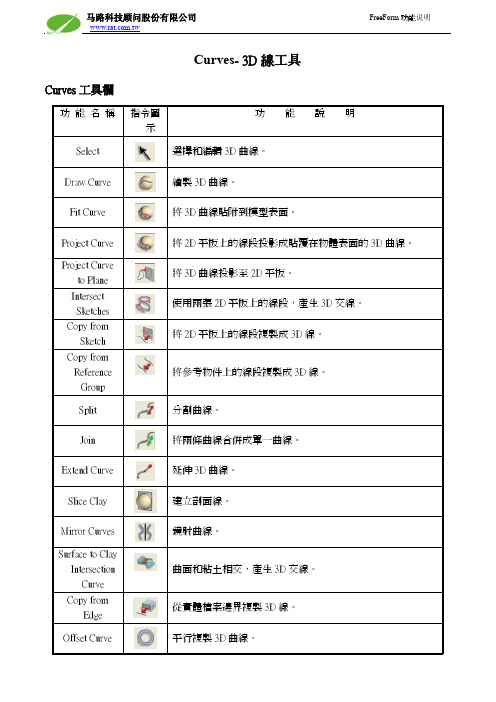
Curves- 3D線工具Curves工具欄一、 繪製3D 曲線Draw Curve 指令是在3D 的空間畫線。
二、 投影3D 曲線至模型表面三、 Split 任意分割曲线Split Curve 指令是分割曲線。
注:使用第一项打断曲线时,可按住Ctrl同时选中多条线,再选定一个点进行分割。
四、合併3D 曲線Combine Curve 指令將兩條曲線合併成單一曲線。
步驟一:先單擊要合併的其中一條曲線。
步驟二:選取另外一條曲線。
工具使用說明:五、抓取断面线產生單條剖面線剖面線數量反向設定產生多條剖面線剖面線間距確認1. 產生單條剖面線01. 點選Create Plane新增繪圖平板,並調整平板至所需產生剖面線的位置。
02. 點選產生單條剖面線的功能,然後點選Apply確認。
03. 如下圖所示,剖面線將會產生在2D繪圖平板和模型的相交處。
2. 產生多條剖面線01. 點選Create Plane新增繪圖平板,並調整平板至模型的邊緣。
02. 點選產生多條剖面線的功能,然後設定剖面線數量及剖面線間距,即會出現下列預覽畫面,方向若不正確,請點選Flip進行反向設定。
03. 點選Apply確認,即可產生如下圖所示的多條剖面線。
04. 若需在不同軸向產生剖面線,請在不同軸向新增繪圖平板,然後重複上述步驟即可產生不同軸向的剖面線。
六、產生3D交線01. 於2張不同的2D繪圖平板上繪製所需的輪廓線。
02. 點選Intersect Sketches產生3D交線功能,使用兩張2D平板上的輪廓線段,產生3D交線。
03. 下圖為產生的3D交線。
七、3D 曲線Offset複製並Offset 曲線 往內Offset Offset 至模型表面Offset 距離 確認Offset 原始曲線 往外Offset 使用數值進行Offset 清除八、產生螺旋曲線Helix 指令是依據一條3D 曲線為中心,旋轉出螺旋線。
曲線起始的半徑 曲線終止的半徑曲線的起始角度 曲線的圈數九、 Subdivide Curve Loop曲線細分Subdivide Curve Loop 指令是繪制四條邊界線,再細分中間。
NX6_MECHANICAL_FREEFORM_01

Unit 2
单段样条与多段样条的比较
Single Segment Splines 单段样条
• 用一个多项式方程来描述的曲线,其阶次由点数控制
• 单段样条的阶次=点数-1 • 单段样条的点数最多为25。
• 动一点, 整个曲线全动,
• 只能为开口 (Open)样条
Multiple Segment Splines 多段样条
投射曲线 Project 偏置曲线 Offset 桥接曲线 Bridge 曲线的缠绕和展开Wrap /Unwrap 曲线简化 Simplify 曲线连接 Join 镜像曲线 Mirror Curve
样条曲线 螺旋线
Spline
Helixes Law Curve
规律曲线
曲线操作
5
Unit 1 Classification of Curves 曲线的分类
16
Unit 2
Creating Spline 样条的创建
UG的样条曲线为自由形式曲线,可以是3D或2D曲线。 UG的Splines为 非均匀有理B样条(non-uniform rational Bsplines -- NURBS)。 NURBS是 CAD/CAM领域的一种曲线和曲面的标准,用于构造复杂形状的模型。
全息片(Smart Sheet)是全参数化、全相关曲 面。该类曲面由曲线生成,曲面与曲线相 关,修改曲线参数后曲面自动更新。
注意: 片体可以是参数化特征(全息片体)或非参数化特征。全 息片体可用Edit Feature Parameters…进行编缉。
2
Unit 1 Process of Free Form Feature Modeling
2. 构建”主要(primary)” 片体_利用过曲线;直纹;过曲线网
- 1、下载文档前请自行甄别文档内容的完整性,平台不提供额外的编辑、内容补充、找答案等附加服务。
- 2、"仅部分预览"的文档,不可在线预览部分如存在完整性等问题,可反馈申请退款(可完整预览的文档不适用该条件!)。
- 3、如文档侵犯您的权益,请联系客服反馈,我们会尽快为您处理(人工客服工作时间:9:00-18:30)。
Creating Features from Section Strings(由截面曲线生 成自由曲面)
Creating Features from Faces(由已有曲面生成自 由曲面)
Creating Features from Faces, Tangency Strings, Limits, and More(由已有曲面、相切曲线等条件 生成自由曲面)
尽管UG中自由曲面特征建模是较复杂也是较难掌握的建模方法, 但以下介绍的都是自由曲面最基本的建模方法,只要您能循序 渐进,多多练习,相信您能掌握UG自由曲面建模的基本方法。
2018/10/19 1
自由曲面特征概况
下面您将要学习如何创建自由曲面特征, 以下显示的是几个自由曲面例子。
2018/10/19
UG NX
注意,您修改这些 参数以后,将对以 后创建的物体起作 用。
2018/10/19
15
建模参数设置Modeling Preferences
Body Type:控制体的类型,即创建的体是实体还是片体,该选项用 于Through Curve Mesh,Through Curves,Swept,Section及 Ruled 等自由曲面特征的生成以及Extruded Body 和Revolved Body 的生成。 片体没有厚度,实体有一定的厚度(体积)。 Free Form Construction Result :控制曲面类型,即创建的是平 面还是B样条曲面,该选项用于Through Curves,Through Curve Mesh,Swept和Ruled等自由曲面特征的生成。 Curve Fit Method:控制曲线拟合方法(曲线用样条逼近),如果 生成的曲线可以用任意阶的样条精确表示,则生成样条曲线。
UG Free Form Feature(自由曲面) --第一部分
在下面的课程中,您将学到:
自由曲面特征基本概况 如何创建基于点集的自由曲面(Through Points, From Poles,From Point Cloud) 如何创建基于曲线的自由曲面(Through Curves, Ruled,Through Curve Mesh,Swept,Section)
基于点集的自由曲面
基于点集的自由曲面有三种: Through Points - 过点生成曲面
From Poles - 由极点生成曲面
From Point Cloud - 由云点生成曲面
2018/10/19
8
基于曲线的自由曲面
基于曲线的自由曲面有5种: Ruled - 直纹曲面 Through Curves - 过曲线 Swept - 扫描曲面 Through Curve Mesh - 过曲线网格 Section Body - 截面曲面
2018/10/19
9
基于面的自由曲面
基于面的自由曲面有10种: 1. Offset Surface - 偏移曲面 2. Thicken Sheet - 加厚片体 3. Enlarge - 增大曲面 4. Extension - 延伸曲面 5. Fillet Surface - 倒圆曲面
2018/10/19
4
2018/10/19
自由曲面创建类型
要创建自由曲面,您必须先定义或选择构造几何(如 点、曲线、片体或实体的边或面、或其他物体),然 后生成自由曲面。
下面是一些自由曲面的创建方法,但并非全部。
2018/10/19
5
Creating Features from Points(由点集生成自由曲面)
2018/10/19
13
自由曲面的编辑
自由曲面编辑可以用特征参数编辑 EditFeatureParameters选项: 也可以用自由曲面编辑EditFree Form Feature选项:
2018/10/19
14
建模参数设置Modeling Preferences
您可以设置建模参数,如长度误差、 角度误差、密度及密度单位、曲面 网格等。 选择菜单PreferencesModeling。 出现Modeling Preferences 对话框。
11
基于面的自由曲面
6. Face Blend - 过度曲面 7. Soft Blend - 软过度曲面 8. Bridge - 过桥曲面 9. Trimmed Sheet - 修剪曲面 10. Bounded Plane - 边界平面
2018/10/19
12
基于其他几何的自由曲面
基于其他几何的自由曲面有两种: 1. Quilt - 缝合曲面或拼接曲面 2. Midsurface - 中面
Cubic:3阶样条曲线; Quintic:5阶样条曲线,它更逼近于原来的曲线特性。
16
2018/10/19
Байду номын сангаас
建模参数设置Modeling Preferences
Distance Tolerance:距离误差,即理论片体和系统 生成的实际片体之间的最大许用距离,用逼近方法生 成的特征要求有一个距离误差。 Angle Tolerance:角度误差,即理论片体的法线和 系统生成的实际片体的法线之间的最大许用角度。 在建模时,有时即使满足了距离误差,系统还是有可 能增加曲面片以满足角度误差。如果您发现片体生成 时速度很慢,则可能需要增加角度误差,或者,您可 能把角度误差设得太大了。 Density:密度(注:它对以后创建的实体有效)。 Density Units:密度单位,共有4个选项:
2
自由曲面特征是指由一个或多个B-样条曲面或修剪过的平面组成的 片体或实体。自由曲面可以直接创建在实体上,也可以单独创建,其 外形与实体很相似,但不一定要求封闭。
2018/10/19 3
打开相应的工具栏(图标)
为了便于选择自由曲面的创建及编辑图标,需要打开相应 的工具栏(图标)。 选择菜单ViewToolbarsCustomize。 出现Customize 对话框,打开相关的工具栏(即Free Form Feature, Feature Operation, Form Feature, Edit Feature, Edit Free Form Feature) 。 有些图标选项在一开始时不一定就出现在工具栏上,所以 需要定制工具栏。当然您若不习惯用图标,也可以用文字 菜单。 定制方法:选择Customize 对话框里的Commands, 然后选 中列表里的工具栏名称,在左边打开要显示的图标选项。