CONTOUR XLRiC 测距测高仪(带罗盘)中文说明书
激光测距仪操作文档

激光测距仪操作说明书一.激光测距仪硬件介绍HUDLCD显示器RS232数据串口扳机LCD显示器二.测距仪的技术指标a)罗盘(抗磁性传感器,Post-Fluxgate 技术)i."0.5 º 精确度b)磁倾仪i."0.1 º 倾斜精度ii."40 º 倾斜范围c)测距i.精度–测85米外的白目标精度为0.1米ii.最大距离–1850米(反射目标)iii.最小距离–3米iv.高压输电线175米v.杆状标志400米vi.树(无叶)400米vii.建筑物,树(有叶)800米三.激光测距仪的基本操作3.1 如何校对激光测距仪●开启电源●按“MENU” 健●用>?键来进行功能选择●选择“COMP” 并按下“Enter” 键●选择“CAL” 并按下“Enter” 键●LCD显示窗显示“Initializing Please Wait!” &“Rotate Unit for Calibration” 信息●以射击的姿势扣住扳机. LCD显示窗显示“Data PointCount” 信息●慢慢转动Contour枪1-2圈. 每圈用45-60秒钟完成●慢慢转动Contour枪1-2圈. 每圈用45-60秒钟完成●在转动中,慢慢地从上到下,从左到右移动(±40º的范围)●虽着 Contour 的移动, 你将看到数据点(Data PointCount) 在增加。
当其值增加到275时,罗盘校对操作就完成了。
松开板机,系统恢复原来的设置●每次系统上电都必须要重复以上操做3.2 开机自检自检信息:仪器开机后将进行自检,自检信息将显示在LCD 显示屏上:Selft TestControur XLRic当自检信息结束后回到以前的测量界面时,说明自检成功,否则会出现以下错误信息:End Of Self Test*** Fall3.3 标准测量模式下的测量标准模式是仪器在开机后默认的模式,在这种模式下,仪器将显示所测目标的距离、方位和倾斜值。
contour介绍

模式功能详解
1,标准模式(R/B/I MODE)
-瞄准目标后,按动测量按键,将会在LCD显示器上显示”仪器到目标的距离”, “仪器到目标的水平偏角(磁偏角或真北偏角)”,“仪器到目标的垂直倾角”; -注意:要想获得比较精确的结果,瞄准目标后,让仪器稳定2-3秒后再按动测量 按键测量; -持续按住仪器操作键,可以连续测量;松开按键后,显示最后一个测量结果;
响);
模式功能详解
6,坡度(梯度)测量模式(Slope/Grade Mode)
-该模式用于测量两点间的连线的坡度或梯度; -测量过程是这样的:先测量一个点,再测量另外一个点,得到坡度或梯度值; -如果第二个测量点比第一个测量点高,那个坡度或梯度是正的;否则为负值;
模式功能详解
7,3点弧垂测量模式(3-shot Sag Mode)
-该模式用于测量两个线杆间导线的下垂垂度; -测量过程是这样的:先测量一个线杆上线的连接点,再测量另外一个线杆上的连 接点,然后按住测量按键扫描下垂部分的最底部;等到观察窗里面显示0.0-0.3 时,松开按键,读取结果; -注意:扫描线的底部时,测量按键不能松开;
模式功能详解
8,水平线测量模式(Horiz Line Mode)
仪器的主要性能
1,基本测量功能
- 距离测量,倾斜角度测量,磁偏角或真北偏角测量; - 距离测量范围是3米-1850米,测量分辨率是0.1米;精度小于0.2米 - 倾斜角度测量范围是+/-40度(显示为50-130度);精度0.2度 -水平角度测量范围0-360度;精度0.5度
Contour XLRic 测距仪使用说明

Contour XLRic 测距仪使用说明概要信息介绍恭喜你,你已经接触到了拥有最先进技术的新一代服务于测距和其他测绘应用的仪器。
这种紧凑型手持式测距仪能在不需要棱镜和制动反射介质的情况下应用于多种距离测量。
系统包含了预置的功能强大的测绘软件,同时也提供了集成型数字罗盘和倾斜仪模块。
此设备还改进了操作功能和使用方法,使其操作、维护和学习更简便。
改进的方面包括:测距精度和分辨率有所提高。
尺寸和重量缩小。
防水程度达到IP67和NEMA6级。
电池组可拆装、寿命延长。
提供带低压报警的电源管理功能和用户可选择的“Power Off”模式以保护电力。
方形十字丝设立激光束大小。
恶劣天气操作模式可提高在雾,雪,雨,尘,天气中的观测效果。
提供橡胶缓冲挡用于保护仪器重要部位。
符合人体工程学设计的处理减少手臂和手腕的疲劳。
大屏幕液晶显示屏有助于控制和操作显示。
对于了解常规测量或激光设备仪器的操作者来说,掌握激光测距仪的使用易如反掌,同样,对于首次使用该仪器的人来说也将会发现掌握其操作是非常简便的,因为它克服了之前的一些传统测绘操作上的不足。
拆封当你第一次拿到测距仪的时候,请仔细检查装运箱有没有损坏。
有任何的破损痕迹都应立刻与仪器公司联系。
将箱子朝上打开,对照以下明细列表进行核查:激光测距仪一台;操作手册一本;电池一块;充电器一台;软件便携包一个。
如果上述任何东西缺失,可以联系测距仪的客户服务部门,电话:770-409-9660,e-mail:techsupport@.。
拨打包装清单上的电话能迅速得到售后服务。
请注意其他的附件将被详细列表于包装清单上。
装运箱仪器被装在耐用防水的装运箱内并用包装绳包好。
它足以承受仪器、电池和电线的重量。
看清装运箱上的方向指示标签,以保证仪器能安全搬运。
功能介绍此测距仪是个可用于距离测量,方位角、倾角测量的多功能仪器。
Contour XLRic仪器运用的是激光雷达技术进行测距。
当拉动扳机,仪器每秒发射出数以百计的不可见镭射激光脉冲。
xlc-1型多用测试仪使用说明书
xlc-1型多用测试仪使用说明书
1、先将仪器和电脑用数据线连接好,再进行开机的操作。
2、将仪器电源线介入220V电源,打开后部的开关,再按“开”键,此时会有开机画面显示,打印机指示灯亮。
仪器需自检5秒钟,自检结束后再按“确认”键,便会进入待机状态。
3、进行样品检测:在检测状态下,放入显色好的样品液,盖上盖子,至少5秒后按<检测>键,即可完成一次样品检测,此时屏幕显示样品浓度。
(注意通道放显色液时,不能按调零)。
4、选择仪器中的“设置”,便可通过<↑><↓>来调节检测时间。
CONTRACER CV-2100系列2 Contour测量系统操作指南说明书
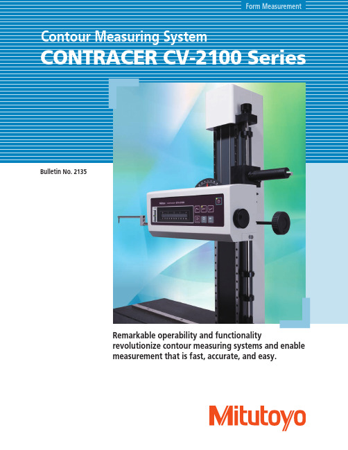
Form MeasurementBulletin No. 2135Remarkable operability and functionalityrevolutionize contour measuring systems and enablemeasurement that is fast, accurate, and easy.After a thorough analysis of all contour measurement operations, key operating functions are redesigned to enable fast, accurate and easy measurements.The operation flow is significantly shortened by arranging the switches for stylus position change, measurement start/stop and return on the front of the drive unit. These operations are required for every single measurement cycle. This centralized panel can therefore reduce the workload of A jog shuttle covering a wide range of speed is a standard feature.The drive unit can be moved easily to the measurement position by usingthe jog shuttle.Easy operation with X-axis jog shuttleCentralized front control panelKey operation buttons are now mounted onto the X-axis drive unit to reduce set-up time and improve high-volume repetitive measurement processess.Inside: Fine feedOutside: Coarse feedSpeed range: 0.02 - 20mm/sThe newly designed stand allows operators to quickly and easily move the drive unit to and from the measurement height without having to push or pull.Moreover, this stand is equipped with a reference stop for quick repositioning to the measurement height, which ensures an easy and highly efficient measurement flow.By enabling faster X-axis movement and enhancing the stylus up/down functions, the drive unit can return to the measurement start position after auto-displacement of the stylus. This is especiallyuseful when high volume repetitive measurements are being executed by a part program.A quick-vertical-motion stand with remarkable operabilityHighly efficient measurementHandleFine-feed knobUpside Bottom"Pursuing high accuracy is our mission"Introducing a new highly accurate digital scaleEasy setup for highly accurate and efficient measurementThe detector unit (Z1 axis) is equipped with a highly accurate arc scale. This scale directly tracks the arc trajectory of the stylus tip so that the most accurate compensation can be applied to the scale output, which leads to higher accuracy and resolution.The highly accurate digital arc scale not only improves measurement accuracy, but can also be set up easily.Measurement range of detector: 50mmAccuracy: ±(2.5+|0.1H |) μm, where H is displacementfrom mid-range position (mm)Resolution: 0.1μm (over entire measurement range)Light emitter receiverThe Circular ScaleDigital-scale detectorConstant ResolutionOperators are free from bothersome operations such as measurementmagnification switching and calibrating each magnification as required for analog instruments.The combination of high accuracy and excellent operability allows for increased support of a wide range of measurement needs.X-axis inclination handle is a standard featureA range of options available according to the applicationThe CV-2100 series * is equipped with a drive unit inclination mechanism that enables inclined-plane measurement without changing settings.Inclination angle (MAX): ±45°(For CV-2100M4)CV-2100N4Manual column stand for CV-2100N4*2CV-2100M4Desktop PC*1: If the CV-2100N4 is operated without the dedicated manual stand, the measuring range of the Z axis might be reduced, depending on the installation conditions. If you are considering using the CV-2100N4 without the stand, contact your local Mitutoyo sales office for advice.*2: Optional accessory (refer to page 13).*1* For CV-2100N4, a manual column stand No.218-042 (refer to P13) is required (optional accessory.)Contour Analysis Software: FORMTRACEPAKFORMTRACEPAK functions offer total support for measurement system control, surface roughness analysis, contour analysis, contour tolerancing, and inspection report creation.To make only a single measurement, you can create a part program in the single mode. To measure multiple workpieces of an identical shape, you can use the teaching mode.Since you can embed the entire flow, from making measurement to printing a report, into a part program, you can efficiently make measurements, analyze data, and output a report. A function is also provided that enables you to insert comments accompanied with photographs at desired timings, enabling you to embed the roles described in a measurement procedure document that specifies important points such as work settings.To make immediate measurements, you can use the pull-down menu to easily select and call up the desired operating procedure.Online help that can be viewed any time is incorporated into the software. In addition to index and keyword searches, a status saving help button, which displays menus and Windows help with a click of the mouse, is provided.You can hide buttons that are not used frequently. For example,you can choose to display only those buttons that are usedfrequently and increase the size of the displayed graphics window,thereby customizing the window to suit your needs.You can switch the language* to be used in the measurement,analysis, and layout windows.After measurements have been made, you can switch to another language and create a report in that language. This function can be used worldwide.* Supported languages: Japanese, English, German, French, Italian, Spanish, Polish, Hungarian, Swedish, Czech, Simplified Chinese, Traditional Chinese, Korean, Turkish, Portuguese.* Online help function supports only Japanese and English.Measurement controlOnline help function *Multiple language support (15 languages)Button-editing functionCircle and line automatic determination function Using the circle/line auto-fitting command, you can automatically calculate all circles and lines contained in the data without having to click the command button each time.Removal of abnormal points functionIrregular defects in the data are filtered out from the calculation. This function can effective when specifying the calculation range for locations at which the boundary between circle and line is difficult to determine.Text output of the calculation result and graphics data You can output the calculation result as text (in csv or txt format), output graphics data obtained from measurements as point-string data to a text file or CAD file (in the DXF or IGES format), or copy the data to the clipboard. Combined with commercial document or statistical processing software, this feature can be used to share data with computers that do not have dedicated analysis softwareinstalled or execute CAD-based reverse engineering.Contour analysis functionA wide variety of commands, which form the basicelements for analysis, are provided, including those forpoints (10 kinds), lines (6 kinds), and circles (6 kinds).A rich set of commands that combine these elementsto calculate angles, pitches, and distances, a contourtolerancing function, and a design value generationfunction are also provided as standard features. Thesefunctions, combined with the function that allowsyou to customize the calculation command buttons byhiding less frequently used commands, let you tailorthe window according to the user environment.Simple pitch calculation functionYou can efficiently analyze the pitch between identical shapes,such as a screw pitch or the distance between circles (center-to-center pitch), bysimply specifying thedesired range usingmouse operations.Example of range specification for screw threadpitch with rectangular tool.Contour-tolerancing function as a standard featureThe best-fit processing function that moves the coordinate values of the design data and measurement data to the optimum positions is provided as a standard feature. Measurement results can be displayed as graphics that show deviations of the measured contour from nominal with the tolerance values expanded in each coordinate for easy comparison. Results can also be output as a text file, or utilized as feedback data for machining systems.Contour AnalysisExample of contour-tolerancing result in graphical form Example of contour-tolerancingresults output as numeric valuesContour Analysis Software: FORMTRACEPAKContour AnalysisDesign value generation functionYou can generate design data from CAD data (DXF or IGES file) or text data. Furthermore, since you can also convert measurement data into design data, you can save parts data prior to use (testing) as design data and effectively utilize it for checking the wear following use (testing).Data combination functionYou can combine partial data collected separately from a work-piece (made necessary due to shape characteristics) into a single graphic for convenient analysis.Calculation command repetition settingWhen identical shapes have the same pitch, you can analyze all of the shapes in a batch by specifying a single analysis location and the pitch.Best-fit processing function for measurement point stringsThis function tries to fit the measurement points to the stored reference data on the same coordinate system. It can eliminate the effects of a shift that may occur when setting the workpiece during automatic analysis.Data superimposition commandYou can superimpose two sets of data by detecting their charac-teristic points. Use the mouse to drag and move the measurement point strings to the desired positions to be superimposed.Integrated layoutYou can use simple operations to lay out graphics obtained from measurements as well as measure-ment results for surface roughness, contour, and roundness on a single page.Furthermore, since the program now allows you to specify a saved file and paste it, you can easily paste results from multiple files.Note: the optional ROUNDPAK roundness/cylindricity analysis program is required. (Ver. 7 or higher)Element information barThis bar displays the attribute values of the pasted items, allowing you to easily check the contents of the pasted measurement data files.System layout printingBy simply selecting the items to be output, you can automatically lay out the page to be printed.Use this feature when you wish to simplify the printing task.Using the mouse to drag and drop the analysis content displayed in the element insertion bar, you can paste it into the layout. From the contour analysis result, you can also select the analysis result for a circle or line alone and paste it in position.Saving the result as a web pageSince you can save the result in html or mhtml format, which can be displayed using Internet Explorer or Microsoft Word, you can check the result even on a PC on which no layout-editing program is installed.Report creation functionYou can freely assemble measurement results/conditions/graphics as well as comments/circles/lines/arrows, and print them out in a measurement result report. Furthermore, since you can paste bitmap files, you can also add a workpiece image or company logo to the layout.You can also save the created layout and use it again later for similar measurements.Optional Accessories3-axis Adjustment Table: 178-047Table and fixture systemsThis table helps make the adjustments required when measuring cylindrical surfaces. The corrections for the pitch angle and the swivel angle are determined from a preliminary measurement and the Digimatic micrometers are adjusted accordingly. A flat-surfaced workpiece can also be leveled with this table. By using Mitutoyo’s 3-axis adjustment table, the workpiece can be aligned and leveled easily, simply by following the FORMTRACEPAK guidance. No experience or special expertise is required.Guidance display when using 3-axis adjustment tableRotary vise218-003V-block 998291Precision vise 178-019Cross-travel table218-001 (mm), 218-011(inch)Cross-travel table218-041 (mm),218-051(inch)V-block with clamp 172-234, 172-378Holder with clamp 176-107Swivel center support 172-197Center support riser 172-143Center support 172-142Leveling table 178-043-1 (mm), 178-053-1 (inch)Digital Leveling table 178-042-1 (mm), 178-052-1 (inch)Leveling table 178-016Leveling table (for D.A.T.)178-016Calibration stand *112AAG175*1 Required for calibrating in bulk by mounting straight arm/small-hole stylus arm without using cross-travel table and Y-axis table.Optional Accessories3.94”.47”218-042 *Except measuring unit (CV-2100N4)Vertical adjustment range: 12.6"(320mm)Inclination angle (MAX): ±45°Dimensions (W×D×H) : 23.6"x17.7"x29.1"(600×450×740mm)Mass: 242 lbs (110 kg)25.7”x18.5”x26.4”(640×470×670mm)(1000×500×660mm )(1200×750×670mm )Example combination: with monitor arm but no side table *2 (tester and PC not included)Vibration isolators (Desk types)Manual column stand for CV-2100N4Vibration isolators (Desktop types), floor stand and tablesExample combination: with a side table (tester and PC not included)* Quick-vertical-motion function is not availableDesk type 12AAK110Monitor arm *112AAK120Side table *212AAL019*1 Used together with vibration isolator (12AAK110).*2 User to provide a printer rack.Desk typesArms and StylusTip shape: One-sided cut (Tip Angle: 20°)Tip shape: Cone (Tip Angle: 30°)Tip radius: 25µm Tip Material: CarbideTip Material: Carbide145Intersecting cut stylusCone stylusBall stylusFor small-hole stylus SP-11/31For small-hole stylus SP-12/32For small-hole stylus SP-13/33Straight arm Eccentric armFor small holeTip Angle: 12°Tip radius: 25µm Tip Material: CarbideTip Angle: 20°Tip radius: 25µm Tip Material: CarbideTip Angle: 20°Tip radius: 25µm Tip Material: CarbideTip radius: 25µmTip Material: Sapphire·Carbide (SPH-79: Diamond)Tip Angle: 20°Tip radius: 25µm Edge width: 3mm Tip Material: CarbideTip Material: Carbide* Select an arm and stylus that match the type of measurement you require.Type of arm Arm No.Part No.Adaptation stylus No.H: Inch (mm)Type of stylus Stylus No.Part No.Adaptation arm No.H: Inch (mm)Arms (option)Styli (option)Measuring area T-groove dimensions (CV-2100M4)SpecificationsSpecificationsDimensionsCV-2100M4Unit: inch(mm)CV-2100N42.87”Note: All information regarding our products, and in particular the illustrations, drawings, dimensional and performance data contained in this printed matter as well as other technical data are to be regarded as approximate average values. We therefore reserve the right to make changes to the corresponding designs. The stated standards, similar technical regulations, descriptions and illustrations of the products were valid at the time of printing. In addition, the latest applicable version of our General Trading Conditions will apply. Only quotations submitted by ourselves may be regarded as definitive.Mitutoyo products are subject to US Export Administration Regulations (EAR). Re-export or relocation of our products may require prior approval by an appropriate governing authority.Trademarks and RegistrationsDesignations used by companies to distinguish their products are often claimed as trademarks. In all instances where Mitutoyo America Corporation is aware of a claim, the product names appear in initial capital or all capital letters. The appropriate companies should be contacted for more complete trademark and registration information.© 2014 Mitutoyo America Corporation, Aurora IL2.5M – 1213-04 Printed in USA, March 2014Aurora, Illinois(Corporate Headquarters)Westford, Massachusetts Huntersville, North CarolinaMason, OhioPlymouth, MichiganCity of Industry, California Birmingham, AlabamaRenton, WashingtonOne Number to Serve You Better 1-888-MITUTOYO (1-888-648-8869)。
高度测量仪的功能参数介绍 测量仪操作规程

高度测量仪的功能参数介绍测量仪操作规程高度测量仪(划线仪)紧要应用于工件划线及标定;同时也用于测量高度及间距。
高度测量仪(划线仪)功能: 1、ON/OFF开关; 2、RESET清零装置;高度测量仪(划线仪)紧要应用于工件划线及标定;同时也用于测量高度及间距。
高度测量仪(划线仪)功能:1、ON/OFF开关;2、RESET清零装置;3、mm/inch转换;4、转换正方向;5、DATA数据传输;6、PRESET输入一个数值;7、容栅测量系统,电池寿命约2年,最长达3年;8、最大测量速度1.5m/s(60英寸/s);9、数据输出可以选择:USB,OPTO RS232C,Digimatic;10、高对比度LCD,字体高12mm;11、兼顾的重型底座,把持便利;12、接触表面经研磨及硬化处理,有助于长期平滑的移动;13、尺框及尺架由经硬化处理的不锈钢制成;14、手轮用于定位及测量;15、微调装置;16、锁紧螺丝;17、划线爪可折装,尖端为硬质合金;18、标准配置:划线爪,纸箱,电池,操作说明书;高度测量仪(划线仪)技术参数:量程:350mm;辨别力:0.01mm;示值误差:0.04mm;重量:7kg;外形尺寸:180*98*580mm;高度测量仪(划线仪)技术参数:量程:600mm;辨别力:0.01mm;示值误差:0.05mm;重量:8kg;外形尺寸:180*98*835mm;可选附件:1、划线爪,尖端为硬质合金;2、表夹,用于装夹指示表;3、电池,3V,型号CR2032;4、数据线USB,2米;5、数据线Opto RS232C(2m);6、带SUB—D,9针插头;7、数据线Digimatic(2m);8、带10针扁插头;—专业分析仪器服务平台,试验室仪器设备交易网,仪器行业专业网络宣扬媒体。
相关热词:等离子清洗机,反应釜,旋转蒸发仪,高精度温湿度计,露点仪,高效液相色谱仪价格,霉菌试验箱,跌落试验台,离子色谱仪价格,噪声计,高压灭菌器,集菌仪,接地电阻测试仪型号,柱温箱,旋涡混合仪,电热套,场强仪万能材料试验机价格,洗瓶机,匀浆机,耐候试验箱,熔融指数仪,透射电子显微镜。
测距仪怎么使用

测距面板示意图.................................................................................................................................................. 4
测距仪使用说明书
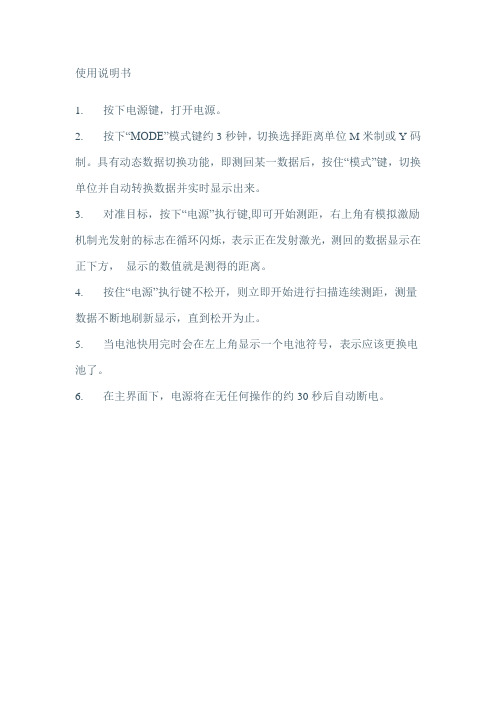
使用说明书
1. 按下电源键,打开电源。
2. 按下“MODE”模式键约3秒钟,切换选择距离单位M米制或Y码制。
具有动态数据切换功能,即测回某一数据后,按住“模式”键,切换单位并自动转换数据并实时显示出来。
3. 对准目标,按下“电源”执行键,即可开始测距,右上角有模拟激励机制光发射的标志在循环闪烁,表示正在发射激光,测回的数据显示在正下方,显示的数值就是测得的距离。
4. 按住“电源”执行键不松开,则立即开始进行扫描连续测距,测量数据不断地刷新显示,直到松开为止。
5. 当电池快用完时会在左上角显示一个电池符号,表示应该更换电池了。
6. 在主界面下,电源将在无任何操作的约30秒后自动断电。
- 1、下载文档前请自行甄别文档内容的完整性,平台不提供额外的编辑、内容补充、找答案等附加服务。
- 2、"仅部分预览"的文档,不可在线预览部分如存在完整性等问题,可反馈申请退款(可完整预览的文档不适用该条件!)。
- 3、如文档侵犯您的权益,请联系客服反馈,我们会尽快为您处理(人工客服工作时间:9:00-18:30)。
Contour XLR ic Operator’s Manual操作手册LaserCraft Inc.1450 Oakbrook Drive,Suite 900Norcross,GA 30093TEL:770-409-9660 * Fax:770-409-9649一、简介恭喜您拥有了一台高科技、功能强大的激光测量系统!在使用本仪器之前,我们建议您务必仔细阅读操作说明书。
这将有助于您正确操作该仪器,同时避免仪器的损伤和操作的失误。
和Contour 系列手持激光测量系统中的Contour XLRi比较起来,Contour XLR ic在内部又集成了一个高精度磁通量数字罗盘。
配合高精度磁通量数字罗盘,XLR ic在功能就比XLR和XLRi多了不少。
有了Contour XLRic,您就可以把它和您的GPS系统连接起来,去测量那些无法到达或不容易到达的地方的坐标信息,省时又省钱。
或者您也可以使用它内置的软件计算:树高,倾斜度,面积,周长,空间线段的长度,水平距离,高差等等数据。
由于Contour XLRic配置了数字罗盘和倾斜角度测量仪,所以它完全可以被看作是一个手持式全站仪,可以协助您进行测绘和测量工作。
一级人眼安全的激光测距仪精确地向您报告以下测量数据:距离,方位,倾斜角。
以下是一些必须注意的事项:-禁止在使用或运输过程中挤压或撞击仪器!-运输仪器时,一定要保证包装完好!-任何情况下,都不要私自拆解仪器!-长久不用时,请一定要把电池从仪器中拿出来!-当用户需要结合反射棱镜进行测量时,切忌要装上“滤光片”(可选附件,编号#: ASY-0055-00)才能进行测量,请联系您的当地经销商购买。
基本配置:Contour XLRic激光测量系统(主机)、英文操作说明光盘NiMH 充电电池、电池充电器、原厂保修卡、豪华仪器箱二、工作模式(详细功能)技术特点-测量距离到:1850米;-测量精度达到:10厘米;-倾斜角度测量;-方位角测量;-周长测量;-面积测量;-电力线高度和垂度测量;-3D空间尺寸测量;-连接GPS工作;-高度测量功能;-“点到点”斜距测量;-水平距离测量和垂直距离测量;-独特的坏天气模式:一般的测距仪在天气不好的情况下,测量的距离往往会大大缩短,甚至无法工作。
Contour系列激光测距仪的“坏天气模式”消除了这种现象。
当天气情况不好的时候,比如:多云,大雾,扬尘,潮湿等,启动该模式,测量起来就和好天气时测量一样轻松快速!三、仪器外观可方便的瞄准被测物体,测出离被测物体的距离四-1)仪器界面介绍四-2)仪器充电/放电介绍放电灯亮的时候——表示正在放电放电灯闪烁的时候——放电工作已经完成充电灯亮的时候——表示正在充电充电灯闪烁的时候——充电工作已经完成四-3)操作模式介绍操作说明:1.安装电池2.接通电源/关断电源:关机——长按2LCD显示屏上看到。
自检过程是一个非常重要的过程,仪器自检可以恢复仪器的正常状态,消除一些小的仪器内部的问题。
开机自检开机自检完毕罗盘校准——自检完毕之后,按上下键移动屏幕中的括号选中主菜单中(COMP),按下,移动括号选中(CAL),按下,屏幕显示:“Initializing Please Wait!”随即出现:“Rotate Unit for Calibration”信息。
以射击的姿势扣住扳机. LCD 显示窗显示“Data Point Count”。
人随仪器原地慢慢转动1-2圈,每圈用45-60秒钟完成,在转动中,慢慢地从上到下,从左到右移动(±40º)。
随着仪器的移动,你将看到数据点在增加。
当其值增加到275时,松开扳机罗盘校对操作就完成了,屏幕显示“Calibration Complete”。
此步骤至关重要,每次仪器上电都必须要重复以上操作,否则势必影响使用中的精确度。
3.背光/声音/HUD明暗的调整按显示屏上显示如下:()”移动到要设定的参数选项那边——按确认。
HUD明暗的调整VOL提示声音调整BKLIT背光灯打开/关闭设定4介绍3点法测量垂度模式通过测量电力线上的三个点,的下垂程度和下垂距离5当按下按“()”移动到要设定的参数选项那边——按确认。
ENVIRO——测量环境的设定按()”移动到ENVIRO位置,——按后,仪器显示,如下图:当遇到下雨,下雪,大雾或沙尘暴天气时,您只需把工作模式选择到“坏天气”模式,您的工作就不会受到任何影响。
在坏天气下使用它,就如同在好天气下使用一样方便,好用。
SERDATA——设定系列参数按()”移动到SERDATA位置,——按认后,仪器显示,如下图选择传输设备D-XMT——测量数据传输/发送设定这个操作是关于:将Contour XLRi 的数据通过RS232接口传输到外部的设备。
按“()”移动到D-XMT位置,——按仪器显示,如下图当选择(ON)时,扣动板机后,LCD 将会有"传输数据?" “CLR OK”选择CLR——按ENTER,表示不传输数据;选择OK——按ENTER,表示传输数据;当选择(AUTO)时,仪器每次测量出的数据将自动传输给外部设备。
当选择(C)时,表示连续传输数据,扣动板机后,自动的以每0.3 秒为单位传输。
BAUD——波特率的设定这个操作是让用户选择波特率的:选择48表示:仪器设定的波特率为4800选择96表示:仪器设定的波特率为9600选择192表示:仪器设定的波特率为19200 UNITS——单位设定按“()”移动到UNITS位置,——按仪器显示,如下图单位的设定和切换可以在:米、英尺、码三个单位间切换。
OFF——关机设定按()”移动到OFF位置,——按仪器显示,如下图5——表示仪器无任何测量操作5分钟后,自动关机;15——表示仪器无任何测量操作15分钟后,自动关机;30——表示仪器无任何测量操作30分钟后,自动关机;ON——表示仪器除认为关机之外,不会自动关机;Contour XLRic提示用户:1.低电压提示音——当电池电压低于9.2 伏时,仪器发出低电压提示音。
低的电压注意出现大约每一二分钟直到电池被用尽。
2.低电压警告音——当电池电压低于8.6 伏时,仪器电池必须进行充电。
五.产品可选附件六.影响仪器“测距仪有效测程”的一些因素:除了目标的反射性对仪器的最大测量能力产生影响之外,进行测距工作时的环境条件也会影响这一指标。
目标的颜色,表面平滑度、形状及尺寸都将影响其反射性和仪器对它的最大测量能力。
对浅色目标通常可以获得更大的量程。
举例来说,与反射性很差的黑色目标相比,红色目标具有更高的反射性,从而仪器可以测得更远。
同时,对光泽度较高的表面的测量范围要高于粗糙表面,而几何尺寸小的目标要比尺寸大的目标难测得多。
仪器指向目标的角度同样也会产生影响。
从接近90度的方向对目标进行测量(目标表面与激光脉冲飞行方向的夹角接近垂直)可以获得更好的测距性能,反之,偏角过大将使得仪器的测量能力受到限制。
此外,工作环境中的光线条件(例如阳光的强弱)同样会对仪器的测距能力产生影响。
外界光线条件越弱,仪器的最大量程越大,相反,阳光照射强烈的天气会降低仪器的最大量程(同时还要考虑到大气条件的影响)。
七.产品的维护与保养⒈仪器维护①经常检查仪器外观及时清除表面的灰尘脏污、油脂、霉斑等。
②清洁目镜、物镜或激光发射窗时应使用柔软的干布。
严禁用硬物刻划,以免损坏光学性能。
③本机为光、机、电一体化高精密仪器,使用中应小心轻放,严禁挤压或从高处跌落,以免损坏仪器。
④清洁的方法,轻轻吹去附着在透镜表面上的灰尘或纤维物(或者使用柔质透镜刷)。
如需清除污渍或指印,请使用柔软棉布按照圆形轨迹擦除。
如果使用了粗糙质地的清洁布或错误的擦拭操作将有可能划伤透镜表面,进而使仪器损坏。
如果需要进行较为彻底的清洁,建议使用光学镜头纸或者使用清洁相机镜头的清洗液或异丙基酒精。
使用清洗液请务必通过清洁布蘸取,不要直接将其倒在透镜上。
⒉故障处理使用人员排除故障仅限于装卸和更换电池组以及一些不需要打开仪器的校验。
发现故障应及时与代理商联系。
严禁私自打开仪器,以防机内高压伤人或进一步扩大故障。
八.保修条款Condition of Warranty本仪器自售出之日起,保修壹年,凡因制造或元器件引起的质量问题,由本公司免费更换零件和维修。
如属于用户使用不慎或贮存和运输不当造成的事故损坏,不属于保修范围。
本产品实行终身维修,超过保修期,本公司只收取部分检修费和维修成本费。
保修时必须提供购买日期(发票日期),产品型号,产品故障说明。
产品维修请联系当地经销商。
九、附录1RS232 MESSAGEThis appendix describes the message that is transmitted when LOG and LCI is selected under the SERDATA menu.The serial data stream from the test connector is RS 232 data. The message format is a proprietary message registered with NMEA. The details of the message follow. Please note the specific content of the data stream depends on which model you have purchased: XLR, XLRi or XLRi. For example, the range only XLR will output the “range” and “range units” fields only while the other models will have added output for their additional functions. It is important to remember, however, that the number of spaces delimited by commas is always the same for each model.NMEA string is as follows:$PLCI,rrrr.r,f,bbb.b,d,m,ppp.p,d,ss.ss,ggg.g,aaaaaaaaa.a,f,ccccccccc.c,f,,,*hh<C R><LF>Field 1: $PLCI (proprietary identifier for LaserCraft Contour Rangefinder)Field 2: rrrr.r = RangeField 3: f = Range units (f = feet, m = Meters, y = yards)Field 4: bbb.b = Bearing (Azimuth)Field 5: d = Bearing units (d = degrees)Field 6: m = Bearing reference (m = Magnetic north, t = True north)Field 7: ppp.p = Pitch (000.0 = down, 090.0 = horizontal, 180.0 = up)Field 8: d = Pitch units (d = degrees)Field 9: ss.ss = SlopeField 10: ggg.g = GradeField 11: aaaaaaaaa.a = AreaField 12: f =Area units (f=sq. feet, m=sq. meters, y = sq. yards, a=acres, h=hectares) Field 13: ccccccccc.c = PerimeterField 14: f = perimeter units (f=feet, m= meters, y = yards)Field 15: dummy fieldField 16: dummy fieldchecksum- hexadecimal, 1byte, Xor’dTypical Examples:XLR unit-Range Only (range at 35.2 feet)$PLCI,0035.2,f,,,,,,,,,,,,,,*hh<CR><LF>XLR i -Range Inclination (range=35.2 feet, inclin=75.2 degrees)$PLCI,0035.2,f,,,,075.2,,,,,,,,,, *hh<CR><LF>Range bearing inclinometer mode$PLCI,0035.2,f,023.6,d,m,075.2,d,,,,,,,,,*hh<CR><LF>2 &3 shot Height, horizontal distance, horizontal line & 3d line modes$PLCI,0035.2,f,,,,,,,,,,,,,,*hh<CR><LF>Slope/Grade mode$PLCI,,,,,,,,01.56,156.4,,,,,,,*hh<CR><LF>Area/Perimeter mode$PLCI,,,,,,,,,,000000256.5,a,000000085.5,f,,,*hh<CR><LF>。