威泰克斯VX-4104 VX-4107说明书
维克斯(Vicker)方向控制器M-2407-S系列产品的使用指南和数据手册说明书
A - 5 bar (75 psi) B - 10 bar (150 psi)
8 Port Relief (Flow direction ‘A’ - ‘T’ port)
00 - None 14 - 140 bar (2030 psi) 15 - 150 bar (2175 psi) 16 - 160 bar (2320 psi) 17 - 170 bar (2465 psi) 18 - 180 bar (2610 psi) 19 - 190 bar (2755 psi) 20 - 200 bar (2900 psi) 21 - 210 bar (3045 psi) 23 - 230 bar (3335 psi) 24 - 240 bar (3480 psi)
Meter In Spring (“B” Port End) (See table)
593335 Retainer
593330 Meter-In Spool S/A
CAUTION Use Guide Pins per Overhaul Manual M-2409-S to align End Covers with Main Body before tightening 470870 Screw.
: Note Press Pin flush after assembly of 485829 Plug
Y 200110 O-Ring
242789 Spring
593336 Poppet
470870 Screw (4 req’d) Torque 85-103 N.m (63-76 lb. ft.)
MCU410-V101-FE版
1-4轴运动控制系统说明书MCU410 – MCU4401.安全须知使用本控制系统前,请您仔细阅读本手册后再进行相关的操作。
仔细阅读本操作说明书,以及用户安全须知,采取必要的安全防护措施。
如果用户有其他需求,请与本公司联系。
工作环境及防护:1.控制系统的工作温度为0-40℃,当超出此环境温度时系统可能会出现工作不正常甚至死机等现象。
温度过低时,液晶显示器将出现不正常的情况。
2.相对湿度应控制在0-85%。
3.在高温、高湿、腐蚀性气体的环境下工作时,必须采取特殊的防护措施。
4.防止灰尘、粉尘、金属等杂物进入控制系统5.应防护好控制系统的液晶屏幕(易碎品):使其远离尖锐物体;防止空中的物体撞到屏幕上;当屏幕有灰尘需要清洁时,应用柔软的纸巾或棉布轻轻擦除。
系统的操作:系统操作时需按压相应的操作按键,在按压按键时,需要食指或中指的指肚按压,切忌用指甲按压按键,否则将造成按键面膜的损坏,而影响您的使用。
初次进行操作的操作者,应在了解相应功能的正确使用方法后,方可进行相应的操作,对于不熟悉的功能或参数,严禁随意操作或更改系统参数。
系统的检修:当系统出现不正常的情况,需检修相应的连接或插座连接处时,应先切断系统电源。
再进行必要的检修。
未得到本公司授权的单位或者个人,不能打开控制系统进行维修操作,否则本公司不予维修。
系统保修说明:保修期:本产品自出厂之日起十二个月内。
保修范围:在保修期内,任何按使用要求操作的情况下所发生的故障。
保修期内:保修范围以外的故障为收费服务。
保修期外:所有的故障均为收费服务。
以下情况不在保修范围内:任何违反使用要求的人为故障或意外故障。
带电插拔系统连接插座而造成的损坏。
自然灾害等原因导致的损坏。
未经许可,擅自拆卸、改装、修理等行为造成的损坏。
其他事项:本说明书如有与系统功能不符、不详尽处,以系统软件功能为准控制功能改变或完善升级,恕不另行通知2.概述本公司研制的运动控制器采用高性能32位CPU,驱动装置支持细分步进电机或者伺服电机,配备液晶显示器,全封闭触摸操作键盘,系统具有高可靠性,高精度,噪音小,操作简单等特点。
VX灭菌锅的SOP
SYSTEC VX系列高压灭菌锅4. 正文:4.1液体灭菌程序:4.1.1打开冷凝水阀门,打开纯净水阀门。
4.1.2接通电源,打开仪器右侧的开关。
4.1.3待显示屏出现’Stop’key=Open READY 时,按Stop键,锅盖打开。
4.1.4将盛有液体的容器整齐的摆放到立式灭菌锅中(上下两层的篮子中均可摆放)。
同时准备1个500ml三角瓶,里面盛有约250ml纯化水,此时将温度探头放入三角瓶中。
4.1.5将锅盖轻轻的压下,自动锁会将锅盖锁紧。
4.1.6用上下箭头键键选择程序11-liquids.4.1.7按start键。
显示屏显示0000,用PARAM键移动光标,用上下箭头键键调节数字,输入密码“0022”。
最后用PROG键确定。
显示屏出现Heating to ster ,即开始升温升压。
4.1.8显示屏上的温度和压力值开始上升,当温度达到121℃时,显示Sterilize (开始灭菌),并出现20分钟的倒计时。
4.1.9当倒计时至“0”时,灭菌结束。
4.1.10此时显示屏显示“Water cool”,即开始自动冷却。
当温度降至80℃,压强降到100KPa时,整个程序完成,灭菌结束。
显示屏会出现’Stop’key=Open ended。
4.1.11按Stop键将锅盖打开。
将灭好的容器取出,备用。
将盛纯化水的三角瓶取出,将温度探头放回原位。
附录:1.当灭菌次数达到100次时,应启动清洗程序(即12-Cleaning),仪器自动清洗。
备用。
2.如立式灭菌锅长时间不用,(例如:周末或节假日)要关闭冷凝水、纯净水阀门。
3.当中途强行终止程序时,按Stop键,当压强降至100KPa时,再按Stop键,此时出现0000,用PARAM键移动光标,用上下箭头键键调节数字,输入密码“0198”。
最后用PROG 键确定。
锅盖打开。
4.2废液灭菌程序:4.2.1、4.2.2和4.2.3同4.1.1、4.1.2和4.1.3。
Vulcan-Hart VSX3, VSX4, VSX5 电子反流蒸汽煮食器操作手册说明书
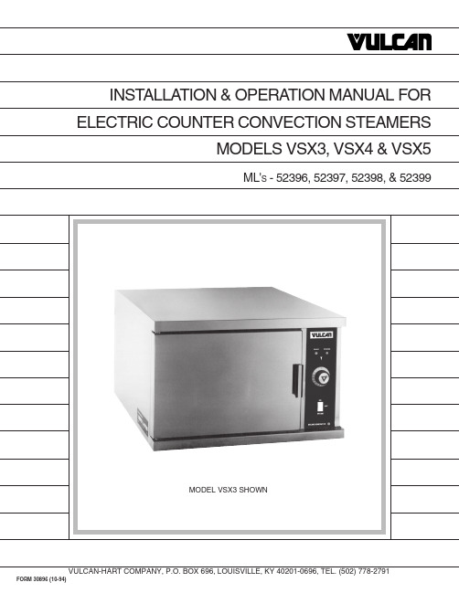
Installation, Operation, and Care ofMODELS VSX3, VSX4, VSX5ELECTRIC COUNTER CONVECTION STEAMERSKEEP THIS MANUALGENERALThe VSX 3, 4, and 5 Steamers are single compartment electric pressureless steam cookers with an internal electric steam generator that maintains water temperature at approximately 205°F. VSX3 is rated 7.5kw as standard; 10kw is optional. VSX4 is rated 10kw. VSX5 is rated 15kw.At high altitude locations a lower temperature is required to achieve atmospheric steaming. Contact your Vulcan-authorized service office to have the thermostat adjusted if the steamer will be operated at high altitudes.INSTALLATIONUNPACKINGImmediately after unpacking the steamer, check for possible shipping damage. If the steamer is found to be damaged, save the packaging material and contact the carrier within 15 days of delivery.Prior to installation, verify that the electrical service agrees with the specifications on the machine data plate which is located on the left side panel.LOCATIONAllow space for plumbing and electrical connections. Minimum clearances are 2" on the sides and 6" on the back for proper air circulation. Allow adequate access for operating and servicing the steamer (36" at the front of the steamer and 15" above the steamer).LEVELING FEET (Standard) OR 4"ADJUSTABLE LEGS (Optional)Thread the four 2" leveling feet shipped in a bag inside the steamer cabinet into the threaded holes on the bottom corners of the steamer. Or, thread the four optional 4" adjustable legs into the threaded holes on the bottom corners of the steamer.LEVELINGUsing a spirit level or pan of water in the bottom of the steamer, adjust the leveling feet or the feet on the adjustable legs to level the steamer front-to-back and side-to-side. After the drain is connected, check for level by pouring water onto the floor of the compartment. All water should drain through the opening at the back of the compartment cavity.1.Place steamer in the desired location on theleveled counter top and mark four corners.Remove the steamer and drill 1/2" holes asindicated in Fig. 1.2.Apply a bead of RTV or other equivalent sealantaround the bottom perimeter edge of the steamer.If anchoring the steamer, this bottom seal isnecessary to meet NSF requirements.3.Set steamer on counter and bolt down securelywith 3/8 - 16 bolts (not supplied).STACKING KITFollow instructions in the stacking kit when installingstacked convection steamers.Fig. 1ELECTRICAL CONNECTIONWARNING: ELECTRICAL AND GROUNDING CONNECTIONS MUST COMPLY WITH APPLICABLE PORTIONS OF THE NATIONAL ELECTRICAL CODE AND/OR OTHER LOCAL ELECTRICAL CODES. WARNING:DISCONNECT ELECTRICAL POWER SUPPLY AND PLACE A TAG AT THE DISCONNECT SWITCH INDICATING THAT YOU ARE WORKING ON THE CIRCUIT.PLUMBING CONNECTIONSWARNING: PLUMBING CONNECTIONS MUST COMPLY WITH APPLICABLE SANITARY, SAFETY AND PLUMBING CODES.Connect the water supply line to the 3/8" NPT (internal thread) copper tube inlet. The 3/8" water line supplies water to both the generator tank and the cooling system where steam is condensed before entering the drain line. Install the line strainer provided. A manual shutoff valve must be provided convenient to the steamer.DRAIN CONNECTIONSThe drain connection (Fig. 2) must be 1" IPS down, preferably with one elbow only, maximum length of 6 feet, and piped to an open gap type drain. CAUTION: In order to avoid any back pressure in the steamer, do not connect solidly to any drain connection.PL-50880GAP DRAINBY CUSTOMER DRAIN VENTFig. 2WATER QUALITYThe water supply connected to this steamer should contain no more than 2.0 grains of hardness per gallon with pH from 6.5 to 8.0. This degree of hardness and pH can easily be obtained with the use of a properly maintained water softener.Water supplies vary from one location to another. A local water treatment specialist should be consulted before installing any steam generating equipment.Untreated water contains scale producing minerals which can precipitate onto the surfaces in the boiler. Due to the temperatures in the boiler, the minerals can bake onto the surfaces and components. This can result in early component failure and reduced product life.Mineral scale on components causes several problems:1.The surfaces of the heating devices become coated with scale, reducing the heat transferefficiency. This can produce hot spots on the heating elements and result in premature failure.2.The water level probes become coated with scale. Scale will bridge across the probe insulator fromthe metal extension which senses the water level in the boiler shell. Once this scale becomes wet, the water level control is unable to maintain the proper water level in the boiler. This situation may cause an electric heating element to fail if the element is not adequately covered by water. Strainers and filters will NOT remove minerals from the water.Refer to REMOVAL OF LIME SCALE DEPOSITS, page 12.VENT HOODSome local codes may require the steamer to be located under an exhaust hood. Information on the construction and installation of ventilating hoods may be obtained from Vapor Removal from Cooking Equipment, NFPA standard No. 96 (latest edition).TESTING PROCEDUREWARNING:THE STEAMER AND ITS PARTS ARE HOT. USE CARE WHEN OPERATING, CLEANING OR SERVICING THE STEAMER. THE COOKING COMPARTMENT CONTAINS LIVE STEAM. STAY CLEAR WHILE OPENING THE DOOR.Once the steamer is installed and all mechanical connections have been made, thoroughly test the steamer before operation.1.Check that proper water, drain, and electrical connections have been made.2.Open water valve. Turn main power switch ON. After approximately 15 minutes, the READY lightshould come on, indicating that the water temperature is 205°F.3.When the READY light comes on, turn the dial timer to 5 minutes. With door open, observe thatno steam is entering the compartment and the COOKING light is not lit.4.Close compartment door. The COOK ING light is lit and steam should be heard entering thecompartment.5.Check drain line to ensure that water from the cold water condenser is flowing through the drainline.6.Open compartment door and observe that steam supply to the chamber is cut off. The READY lightshould come on; the COOKING light goes off.7.Close compartment door and let cooking cycle finish. When timer returns to 0, a buzzer will soundsignalling the end of the cooking cycle. To silence the buzzer, turn the dial timer to OFF.8.To turn the steamer off, turn the main power switch OFF — the steam generator will drain. Leavethe door open to allow the inside to dry out.OPERATIONWARNING: THE STEAMER AND ITS PARTS ARE HOT. USE CARE WHEN OPERATING, CLEANING OR SERVICING THE STEAMER. THE COOKING COMPARTMENT CONTAINS LIVE STEAM. STAY CLEAR WHEN OPENING DOOR.CONTROLSMain Power switchON The boiler will automatically fill and begin heating to the preset temperature.OFF The boiler will drain.DELIME Closes the drain valve while CLR liquid is being poured into the generatorduring the Delime procedure.Ready light Indicates the temperature has reached 205°F and that the steamer is readyto begin cooking.Cooking light Indicates that a cooking cycle is in progress.Timer Set the cooking time (0 to 60 minutes) — steam cooking will begin when thedoor is closed. The cooking cycle will be interrupted if the door is openduring the cooking cycle; resume cooking by closing the door.When done, a buzzer sounds and steam stops being supplied to the cookingchamber. Turn the timer OFF to stop the buzzer.Delime Generator light Indicates that lime scale deposits have accumulated in the steam generatorand that a DELIME procedure should be performed at the next convenientopportunity. See Maintenance, page 12.PREHEATTurn the main power switch ON. When the READY light comes on, set the timer to 1 minute to preheat the compartment. This should be done when the steamer is first used for the day or whenever the chamber is cold. The door should be closed during the preheat cycle. COOKING light is lit.When the buzzer sounds, turn the timer to OFF. The steamer is now ready to cook.COOKAfter the preheat cycle, the READY light should be ON.Place pans of food in the cooking chamber. Close the door. Set the timer. Steam flows into the compartment and the COOKING light is lit. Opening the door will interrupt cooking; resume by closing the door.At the end of the cooking cycle, the COOKING light goes off, the buzzer sounds and steam stops being supplied to the cooking chamber. To stop the buzzer, turn the timer to OFF.SHUTDOWNTurn the main power switch OFF — the boiler will automatically blow down. Leave the compartment door open to allow the inside to dry out.For an extended shutdown, turn the main power switch OFF; turn power and water supply OFF.COOKING HINTSThe steamer efficiently cooks vegetables or other foods for immediate serving. Steam cooking should be carefully time controlled. Keep hot food holding-time to a minimum to produce the most appetizing results. Prepare small batches, cook only enough to start serving, then cook additional amounts to meet demand.PreparationPrepare vegetables, fruits, meats, seafood and poultry normally by cleaning, separating, cutting, removing stems, etc. Cook root vegetables in a perforated pan. Other vegetables may be cooked in a perforated pan unless juices are being saved. Liquids can be collected in a solid 12" x 20" pan placed under a perforated pan.Perforated pans are used for frankfurters, wieners and similar items when juices do not need to be preserved. Solid pans are good for cooking puddings, rice, and hot breakfast cereals. Vegetables and fruits are cooked in solid pans in their own juice. Meats and poultry are cooked in solid pans to preserve their juice or retain broth.Canned foods can be heated in their opened cans (cans placed in 12" x 20" solid pans) or the contents may be poured into solid pans. DO NOT place unopened cans in the steamer.Frozen Food ItemsSeparate frozen foods into smaller pieces to allow more efficient cooking.Use a pan cover for precooked frozen dishes that cannot be cooked in the covered containers in which they are packed if they require more than 15 minutes of cooking time. When a cover is used, approximately one-third additional cooking time is necessary.Cooking time for frozen foods depends on the amount of defrosting required. If time permits, allow frozen foods to partially thaw overnight in a refrigerator. This will reduce their cooking time. Acceptable Pan SizesThe steamer accommodates combinations of 12 x 20" pans, solid or perforated.Model Number of Pans AccommodatedDepth of Pan1" 2.5"4"6"VSX3 VSX4 VSX56810345223122DRAINING THE BOILERDrain the boiler after each day's use to flush out minerals and minimize scale build-up. The boiler drains automatically for approximately 4 – 6 minutes after the main power switch is turned OFF.CLEANINGAt the end of each day, or between cooking cycles if necessary . . .Turn main power switch OFF.Remove pans and racks from compartment and wash in sink.Wash compartment interior with clean water. Never use steel wool or abrasive scouring pads as they will scratch and ruin the general surface appearance of the steamer.Use warm soapy water with a cloth or sponge to clean the door gasket, rinse with warm clear water, and wipe with a dry cloth.Wipe surfaces which touch the door gasket with a cloth or sponge and warm soapy water, rinse with warm clear water and wipe with a dry cloth. CAUTION: Do not allow the door gasket to come in contact with food oils, petroleum solvents, or lubricants.Keep the cooking compartment drain working freely. After cooking grease producing foods, operate the steamer with the compartment empty for 30 minutes at the end of the day, or pour 1/2 gallon of warm soapy water down the drain, followed by 1/2 gallon of warm clear water.Use a clean damp cloth to wipe down the exterior of your steamer.Leave the door slightly open when the steamer is not in use to allow the inside to dry out. Weekly, or more often if necessary . . .Clean exterior with a damp cloth and polish with a soft dry cloth.Use a non-abrasive cleaner to remove discolorations.COOKING GUIDELINESThe steamer steam cooks vegetables, frankfurters, eggs in their shells, and certain other meats or food items at atmospheric pressure.These cooking guidelines are suggestions only. You should experiment with your food products to determine the cooking times that will give you the best results. Variables which affect cooking time include size, weight, thickness of foods, temperature, density, previous condition of the foods (fresh, pre-blanched or frozen) and degree of doneness desired.COOK IN SOLID PANSPRODUCT TIME (minutes)WEIGHT PER PANEggs, Scrambled10 – 128 Doz.Rice, Long Grain25 2 Lb.(Cover with 4 cups water per pound.)Pasta (Place perforated pan insidesolid pan, cover pasta with cold water)Spaghetti, Regular/Vermicelli12 – 15Macaroni, Shells/Elbows15 – 18Noodles, 1/2" wide12 – 15Lasagna Noodles15 – 18Frozen Casseroles, Lasagna35Full PanMeat Loaf, 3 – 5 pound each4015 Lb.BeefGround Chuck20 – 2510 Lb.Sliced as Purchased35 – 4010 Lb.Shrimp, Frozen, 10 per pound5 4 Lb.BeansBaked910 Lb. Can Refried910 Lb. CanCanned Vegetables610 Lb. CanPrunes, Dried12 – 15COOK IN PERFORATED PANSPRODUCT TIME (minutes)WEIGHT PER PAN SEAFOODClamsFrozen10 – 12 3 Doz. Fresh, Cherrystone 5 – 6 3 Doz.King Crab, FrozenClaws421/2 Lb.Legs 4 –641/2 Lb.Lobster Tail, Frozen610 Lb.Lobster, Live, 10 – 12"5 4 Per PanSalmon Fillets, Frozen, 8 ounce each571/2 Lb.Scallops, Fresh4 3 Lb.Scrod Fillets, Fresh 3 – 5 4 Lb.EggsHard Cooked15 4 Doz.Soft Cooked9 – 10 4 Doz.Soft Yoke for Caesar Salad 6 – 8 4 Doz.Chicken — Breasts, Legs, Thighs2015 Lb.Turkey, FrozenBreasts (2)90 6 – 7 Lb. Each Cut Lengthwise5520 – 25 Lb.Corned Beef40 – 75 6 – 8 Lb.Hot Dogs or Wieners380 – 100 Count VEGETABLESAsparagus SpearsFrozen10 – 12 3 Doz. Fresh5 5 Lb.BeansGreen, 2" Cut, Frozen / Fresh6 5 Lb. Lima, Frozen8 5 Lb.Baby Lima, Frozen5 5 Lb.Brussel Sprouts, Frozen6 5 Lb.COOK IN PERFORATED PANSPRODUCT TIME (minutes)WEIGHT PER PAN VEGETABLES, (Cont'd.)BroccoliSpears, Frozen8 4 Lb. Spears, Fresh6 5 Lb. Flowerettes, Frozen6 5 Lb.Cabbage, Fresh, 1/6 Cut8 5 Lb.CarrotsBaby Whole, Frozen87 Lb. Crinkle Cut, Frozen7–8 4 Lb. Sliced, Fresh119 Lb .Cauliflower, FlowerettesFrozen6 4 Lb.Fresh7–8 5 Lb.Celery, 1" Diagonal Cut7 5 Lb.CornYellow Whole Kernal, Frozen5 5 Lb. Cobbettes, Frozen827 Ears16–1880 EarsCorn-On-Cob, Fresh10–1218 Ears16–1854 EarsPeas, Green6 5 Lb.Potatoes, Whole Russet5540 Lb.SpinachChopped, Frozen17 6 Lb. Defrosted5 6 Lb.Fresh Cut3 2 Lb.Squash, Acorn Halves2510 HalvesZucchini, Slices810 Lb.Frozen Mixed Vegetables6–7 5 Lb.FRUITFruit, Blanch for Peeling,Grapefruit, Oranges3Pineapple, Whole for Cutting4MAINTENANCEWARNING: THE STEAMER AND ITS PARTS ARE HOT. USE CARE WHEN OPERATING, CLEANING OR SERVICING THE STEAMER. THE COOKING COMPARTMENT CONTAINS LIVE STEAM. STAY CLEAR WHEN OPENING DOOR.REMOVAL OF LIME SCALE DEPOSITSThe steamer should be delimed at a convenient time after the DELIME GENERATOR light comes on. Use the CLR TREATMENT K IT available from your Vulcan-authorized service office. Follow the instructions in the Kit to delime the steam generator.COLD WATER CONDENSERThe steamer is equipped with a cold water condenser in the rear of the cooking chamber which helps to condense the steam prior to discharge into the drain. The steamer freely vents itself by the negative pressure created by the condensate water drainage. This negative pressure prevents steam leakage around the door gasket and helps draw the steam through the cooking compartment. Steam leakage at the door may indicate a plugged or improperly installed drain.SERVICEContact your local Vulcan-authorized service office for any repairs or adjustments needed on this equipment.。
ACOPOS 3x 400-480 V 1.6 A 0.7 kW 服务器驱动器说明书
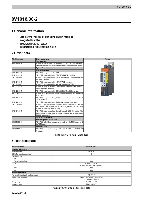
8V1016.00-21 General information•Modular mechanical design using plug-in modules•Integrated line filter•Integrated braking resistor•Integrated electronic restart inhibit2 Order dataTable 1: 8V1016.00-2 - Order data 3 Technical dataTable 2: 8V1016.00-2 - Technical data1)Achievable safety classifications (safety integrity level, safety category, performance level) are documented in the user's manual (section "Safety technology").2)In the USA, TT and TN power mains are commonly referred to as "Delta/Wye with grounded Wye neutral".3)If the module is operated with a mains input voltage of 3x 230 VAC, then automatic nominal voltage detection doesn't work for the DC bus. The UDC_NOMINALparameter must be set to 325 [V] by the user in this case.4)Limit values from EN 61800-3 C3 (second environment).5)The permissible input voltage range is reduced when using motor holding brakes. The input voltage range should be selected so that the proper supplyvoltage for the motor holding brake can be maintained.6)The current requirements depend on the configuration of the ACOPOS servo driveThe inrush current is significantly higher than the value for current consumption and can be estimated according to the input capacitance.7)Valid in the following conditions: 400 VAC mains input voltage, nominal switching frequency, 40°C ambient temperature, installation elevation <500 m abovesea level.8)Value for the nominal switching frequency.9)If necessary, the stress of the motor isolation system can be reduced by an additional externally wired dv/dt choke. For example, the RWK 305 three-phasedv/dt choke from Schaffner () can be used. Important: Even when using a dv/dt choke, it is necessary to ensure that an EMC-compatible, low inductance shield connection is used!10)The module's electrical output frequency (SCTRL_SPEED_ACT * MOTOR_POLEPAIRS) is monitored to protect against dual use in accordance with ECregulation 428/2009 | 3A225. If the electrical output frequency of the module exceeds the limit value of 598 Hz uninterrupted for more than 0.5 s, then the current movement is aborted and error 6060 is output (Power element: Limit speed exceeded).11)OSSD (output signal switching device) signals are used to monitor signal lines for short circuits and cross faults.12)Continuous operation of ACOPOS servo drives at elevations ranging from 500 m to 2000 m above sea level is possible (taking the specified continuouscurrent reductions into consideration).13)Continuous operation of ACOPOS servo drives at ambient temperatures ranging from 40°C to max. 55°C is possible (taking the specified continuous currentreductions into consideration), but this will result in a shorter service life.4 Status indicatorsACOPOS servo drives are equipped with three LEDs for direct diagnostics:Figure 1: ACOPOS servo drive indicatorsDescriptionSolid green The module is operational andpresent and booted, no permanent or temporary errors).Blinking green 1)The module is not ready for operation.Examples:•No signal on one or both enable inputs•DC bus voltage outside the tolerance range•Overtemperature on the motor (temperature sensor)•Motor feedback not connected or defective•Motor temperature sensor not connected or defective•Overtemperature on the module (IGBT junction, heat sink, etc.)•Disturbance on networkSolid orange The module's power stage is enabled.Solid red 1)There is a permanent error on the module.Examples:•Permanent overcurrent•Invalid data in EPROMTable 3: ACOPOS servo drive - LED status indicators1)Firmware V2.130 and later.If no LED is lit up, the ACOPOS servo drive is not supplied with 24 VDC mains voltage.Danger!After switching off the device, wait for the DC bus to discharge for at least five minutes. To avoid a hazard, the current voltage on the DC bus must be measured with a suitable measuring instrument and less than 42 VDC before starting work. An unlit operating LED does not indicate that the device is de-energized!4.1 Status changes when starting up the operating system loaderThe following intervals are used for the LED status indicators:Width of box: 125 msRepeats after: 3000 msTable 4: Status changes when starting up the operating system loaderTable 5: Error status with reference to CAN plug-in module AC1101)Possible errors:- The ACOPOS servo drive is defective.- The plug-in module is defective- The plug-in module is not connected properly in the slot.Table 6: Error status with reference to POWERLINK V2 plug-in module AC114 1)Possible errors:- The ACOPOS servo drive is defective (plug-in module not detected).- The plug-in module is defective- The plug-in module is not connected properly in the slot.- The plug-in module works but is not automatically detected by the ACOPOS servo drive (old bootstrap loader).5 Dimension diagram and installation dimensionsHanging verticallyFigure 2: Dimension diagram and installation dimensions1)For proper air circulation, at least 80 mm clearance must be available above and below the ACOPOS servo drive. Approximately 100 mm clearance isrequired under the ACOPOS servo drive to prevent cabling problems.6 WiringPinout overviewFigure 3: ACOPOS 1010, 1016 - Pinout overview6.1 X1 - PinoutTable 7: X1 - Pinout1)The wiring is not permitted to exceed a total length of 30 m.Information:To obtain a defined reference of ground to ground potential, B&R recommends grounding the COM connections (5-7, 14, 15) on connector X1.6.2 X2 - PinoutTable 8: X2 - Pinout6.3 X3 - PinoutTable 9: X3 - Pinout6.4 X4a, X4b - PinoutTable 10: X4a - Pinout1)If the holding brake is connected via an additional external relay contact (ground-in e.g. via connections S1/S2) instead of only via the internal transistor, thenthe internal quenching circuit has no effect! In this case, the customer must make sure that neither the relay contact nor the braking coil are damaged when switching off the brake. This can be done by interconnecting the coil or - better still - interconnecting the contact with a quenching circuit.Table 11: X4b - Pinout1)If the holding brake is connected via an additional external relay contact (ground-in e.g. via connections S1/S2) instead of only via the internal transistor, thenthe internal quenching circuit has no effect! In this case, the customer must make sure that neither the relay contact nor the braking coil are damaged when switching off the brake. This can be done by interconnecting the coil or - better still - interconnecting the contact with a quenching circuit.Danger!The connections for the motor temperature sensors and the motor holding brake are safely isolated circuits. These connections are therefore only permitted to be connected to devices or components that have sufficient isolation per IEC 60364-4-41 or EN 61800-5-1.Caution!If B+ and B- are swapped when connecting the permanent magnet holding brakes, then the brakes cannot be opened! ACOPOS servo drives cannot determine if a holding brake is connected with reverse polarity!6.4.1 Wiring the connections for the motor holding brakeThe power supply, enabling and monitoring of the output for the motor holding brake can be carried out in three different ways via the wiring of connector X4a:Table 12: Enabling the external holding brake1)The two jumpers are already wired on connector X4a supplied with ACOPOS servo drives.2)External dry contacts can be connected between S1 and S2 and between S3 and S4. This makes it possible to enable the holding brake via external safetycircuits independently of the control integrated in the ACOPOS servo drive.3)Configuration takes place using ParID 90 (1 ... Internal monitoring active, 5 ... Internal monitoring not active).4)Disabling takes place using ParID 90 (5 ... Internal monitoring not active).8V1016.00-2 6.5 X5 - PinoutTable 13: X5 - Pinout6.6 Additional protective ground connection (PE)The protective ground conductor is connected to the M5 threaded bolt provided using a cable lug.Terminal cross sectionsCable lug for M5 threaded boltTable 14: Protective ground connection (PE) - ACOPOSDanger!Before turning on the servo drive, make sure that the housing is properly connected to ground (PE rail).The ground connection must be established even when testing the drive or operating it for a short time!8V1016.00-26.7 Input/output circuit diagramFigure 4: TriggerFigure 5: LimitFigure 6: Enable8V1016.00-2Figure 7: Input/output circuit diagram - ACOPOS 1010, 1016。
VS410说明书
VS410小型高速立式加工中心使用说明书(电气部分)工作台面尺寸(宽×高):650×410出厂编号:宜宾普什机床有限责任公司目录1前言 (1)2机床电气系统主要规格 (2)2.1 机床电源 (2)2.2 主轴 (2)2.3进给轴 (2)2.4 辅助电机 (3)3 机床电气安全 (3)4电气使用条件 (7)4.1总输入电源 (7)4.2 环境条件 (7)5 数控系统主要功能和代码 (8)5.1 主要功能 (8)5.2 辅助功能代码 (8)6 机床电气控制和操作 (9)6.1 面板介绍 (9)6.2 通电前的检查 (13)6.3 机床电器操作 (13)7 机床的维护及一般检修 (26)7.1日常维护和检修 (26)7.2 一般故障的处理 (26)附录A:数控机床常见故障及维修指南 (27)附录B:数控系统随机资料清单 (29)普什机床有限责任公司电气说明书1前言本立式加工中心采用海德汉数控系统TNC620控制,机床采用高刚性、高精度设计,生产效率高,主要特点如下:1)、适用范围广,主要用于:IT 及通讯领域零部件制造;汽车及摩托车小型零部件制造;高精度五金件及小型五金、塑胶模具制造;航空及其他行业精密零部件制造。
适用材料:各类铝材、铝镁合金压铸件、模具钢、铸铁、不锈钢等2)、稳固的立柱床身立柱宽度极其宽大,几乎与床身同宽,为高刚性及稳定性提供了足够的支持。
X、Z 轴在立柱上移动,Y轴为工作台移动,X、Z轴座于宽厚的立柱之上,最大限度缩短了主轴到X轴导轨的距离、最高程度获取了X、Z轴在立柱上的移动时的刚性支持;Y轴与X、Z轴分离,单独着座于床身底座,在床身中央仅做前后方向移动,宽大厚重的底座铸件为Y轴搭载自动交换工作台后的移动提供更大的刚性支持;3)、高速该款机型主轴采用西门子1PH8087-1LG电机,最高速度可达18000rpm,进给轴采用海德汉同步电机,最高进给速度为48M/Min(X/Y/Z 轴),减少了非切屑时间。
s710使用说明书上
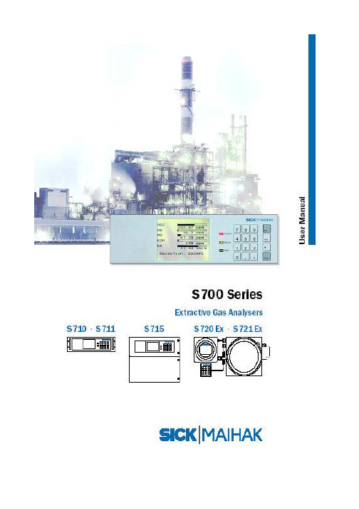
S700 系列模块式微机化气体分析器使用说明书
1
北京北分麦哈克分析仪器有限公司
2.4.4 通过 NOx 转化炉的样气供给 2.4.5 样气接头 2.4.6 样气气路连接 2.4.7 不锈钢气路 2.5 吹洗气连接 (可选) …………………………………………………………………………… 35 2.6 校准气体供给 ………………………………………………………………………………… 35 2.6.1 自动校准气体供给 2.6.2 装有样气制冷器的校准 2.6.3 H2O 分析的特别说明 2.7 打开和关闭壳体 (不包括 S700/S711) ………………………. ……………………………… 36 2.7.1 打开壳体前的安全措施 2.7.2 打开壳体 2.7.3 关闭壳体 2.8 S720Ex/S721Ex 电缆密封适配器的安装 …………………………………………………... 39 2.9 电源连接 …………………………………………………………………………………….... 39 2.9.1 电源连接的安全说明 2.9.2 外接电源保险 2.9.3 改变需要的线性电压 2.9.4 连接电源电缆 2.9.5 内部电源开关 2.9.6 电气保险 2.10 信号连接 ……………………………………………………………………………………... 44 2.10.1 端子连接 2.10.2 信号电压输出 2.10.3 允许最大负载和信号电缆参数 2.10.4 信号连接的电感保护 2.11 测量值输出 …………………………………………………………………………………. 47 2.12 模拟输入 …………………………………………………………………………………48 2.13 开关输出 ………………………………………………………………..……………………48 2.13.1 开关功能 2.13.2 电气功能 2.13.3 接点连接 (针式排列) 2.14 控制输入 …………………………………………………………………………………….. 51 2.14.1 控制功能 2.14.2 电气功能 2.15 本安型输出(可选)…………………………………………………………………………. 51 2.16 数字接口 ……………………………………………………………………………………... 53 2.16.1 接口功能 2.16.2 接口连接
弗诺 VX系列说明书

N e x t l e v e l p e r f o r m a n c e i n a v e r s a t i l e f o r m a t F U N K T I O N-O N E全新一代可灵活多变组合的音响系统INTRODUCTIONVero VX的更小型精巧格式把Vero的声音带到更广阔的场所。
虽然占地面积较小,但Vero VX具有同样智能的声学和机械设计,为其带来领先的音频质量并且易于使用。
Vero VX系统包含有VX90全频域垂直阵列音箱、V124或V221低音音箱、功率放大器柜、阵列音箱吊挂架、音箱搬运滑轮车、音箱地面堆放用硬件、布线及声场投射预测软件等。
虽然占地面积较小,但Vero VX具有同样智能的声学和机械设计简介VX90是一只可组成垂直阵列用的3分频音箱,它在水平方向上平衡配置有四个Funktion-One新设计的钕磁钢驱动单元:• 两个反射加载式、高效的12寸中低音单元• 一个有轴头加载式的宽频段8寸锥体中音单元• 一个在专用的等相衍射波导管上的1寸压缩式单元可用的工作频段为50Hz至20kHz。
水平覆盖角为90度。
可灵活组合垂直阵列音箱VERTICALLY ARRAYABLE LOUDSPEAKER中频段技术VERTICALLY ARRAYABLE LOUDSPEAKERFunktion-One独特的驱动单元及波导技术能使单个换能器覆盖音频频谱的四个倍频程以上,即涵盖了300Hz - 5kHz。
这一方法保证了人声和音乐谐波在时间与空间两者之间保持一致,有利于提高声音的清晰度、可懂度和立体声声像定位。
对压缩式单元的高分频点可提供附加的性能优点,包括增加了动态余量并降低了谐波和调制失真等。
在中频段的总谐波失真通常小于2%(AES 2 - 2012)。
心理声学所揭示的FIR滤波器的使用以及微秒级的时间校正为水平声场覆盖提供了宽广的连续性,同时又保持了瞬态响应频率响应+/-3dB: 60Hz - 18kHz 可用的频段:50Hz - 20kHz 最大声压级*:144dB水平覆盖角: 90°垂直覆盖角: 13°标称阻抗: 4 x 16Ω额定功率: 低音: 2 x 400瓦 中音: 200瓦高音: 50瓦重量:70公斤(154磅)接插件:2个纽翠克NL T8MP斧头号角加载/高频部分的非常高的电声效率是由新颖的低音驱动单元技术来补充的,它显著地增加了实际的功率效率。
- 1、下载文档前请自行甄别文档内容的完整性,平台不提供额外的编辑、内容补充、找答案等附加服务。
- 2、"仅部分预览"的文档,不可在线预览部分如存在完整性等问题,可反馈申请退款(可完整预览的文档不适用该条件!)。
- 3、如文档侵犯您的权益,请联系客服反馈,我们会尽快为您处理(人工客服工作时间:9:00-18:30)。
VX-4100S ERIESO PERATING M ANUALVERTEX STANDARD CO., LTD.4-8-8 Nakameguro, Meguro-Ku, Tokyo 153-8644, JapanVERTEX STANDARDUS Headquarters10900 Walker Street, Cypress, CA 90630, U.S.A.YAESU EUROPE B.V.P.O. Box 75525, 1118 ZN Schiphol, The NetherlandsYAESU UK LTD.Unit 12, Sun Valley Business Park, Winnall CloseWinchester, Hampshire, SO23 0LB, U.K.VERTEX STANDARD HK LTD.Unit 5, 20/F., Seaview Centre, 139-141 Hoi Bun Road,Kwun Tong, Kowloon, Hong KongCongratulations!You now have at your fingertips a valuable communications tool: a VERTEX STAN-DARD two-way radio! Rugged, reliable and easy to use, your VERTEX STANDARD radio will keep you in constant touch with your colleagues for years to come, with negligible maintenance downtime.Please take a few minutes to read this manual carefully. The information presented here will allow you to derive maximum performance from your radio, in case ques-tions arise later on.We’re glad you joined the VERTEX STANDARD team. Call on us anytime, because communications is our business. Let us help you get your message across.I NTRODUCTIONThe VX-4100 Series are full-featured FM transceiver designed for flexible mobile and base station business communications in the VHF or UHF Land Mobile bands. These transceiver are designed for reliable business communications in a wide vari-ety of applications with a wide range of operating capability provided by their lead-ing-edge design.Important channel frequency data is stored in EEPROM and flash memory on the CPU, and is easily programmable by dealers using a personal computer and the VER-TEX STANDARD VPL-1 Programming Cable and CE59 Software.The pages which follow will detail the many advanced features provided on the VX-4100 Series transceiver. After reading this manual, you may wish to consult with your Network Administrator regarding precise details of the configuration of this equipment for use in your applicationFor North American Users Regarding 406 MHz Guard Band The U.S. Coast Guard and National Oceanographic and Atmospheric Admin-istration have requested the cooperation of the U.S. Federal Communications Commission in preserving the integrity of the protected frequency range 406.0 to 406.1 MHz, which is reserved for use by distress beacons. Do not attempt to program this apparatus, under any circumstances, for operation in the fre-quency range 406.0 - 406.1 MHz if the apparatus is to be used in or near North America.VX-4100 S ERIES O PERATING M ANUAL1VX-4100 S ERIES O PERATING M ANUAL2C ONTROLS & C ONNECTORSFront PanelImportant! - All buttons located on the Front Panel are Programmable Function (PF)Buttons, configured according to your network requirements and programmed by your VERTEX STANDARD dealer. The instructions below discribe a typically-con-figured radio.VOL Knob Turn this control clockwise to increase the volume.Microphone JackConnect the microphone plug to this jack.Emergency MicrophoneThe emergency microphone is located behind this small slit. When the emer-gency feature is activated, this microphone is enabled.[MON ], [A ], [ ] Buttons (Programmable Function Buttons)These buttons can be set up for special applications, such as High/Low power selection, Monitor, Talk-Around, etc., as determined by your network require-ments and programmed by your VERTEX STANDARD dealer. (POWER ) ButtonPress and hold in this button for 2 seconds to toggle the transceiver’s power “on”and “off.”C ONTROLS & C ONNECTORSTX/BUSY IndicatorIndicates the transceiver’s Transmit/Receive Status.Steady Red:Transmitting in progressSteady Green:Signaling OffBlinking Green:Busy Channel/Squelch OffChannel Number IndicatorIndicates the operating channel.Transceiver Status IndicatorThe “P1” and “P2” indicators show current transceiver status, which can be customized via programming by your VERTEX STANDARD dealer to meet your communications/network requirements. The possible “P1” and “P2” dis-plays are explained below.VX-4100 S ERIES O PERATING M ANUAL3C ONTROLS & C ONNECTORSRear Panel13.6V DC Cable Pigtail with ConnectorThe supplied DC power cable must be connected to this 2-pin connector. Use only the supplied fused cable, extended if necessary, for power connection. Antenna SocketThe 50-Ohm coaxial feedline to the antenna must be connected here, using a type-M (PL-259) plug.D-Sub 15-Pin Accessory ConnectorExternal TX audio line input, PTT (Push To Talk), Squelch, and external RX audio line output signals may be obtained from this connector for use with acces-sories such as data transmission/reception modems, and external Channel con-trol input etc.External Speaker JackAn external loudspeaker may be connected to this 2-contact, 3.5-mm mini-phone jack.Caution: Do not connect either wire of this line to ground, and be certain that the speaker has adequate capability to handle the audio output (12 W) from theradio.4VX-4100 S ERIES O PERATING M ANUALB ASIC O PERATION OF THE T RANSCEIVER Important! - Before turning on the radio the first time, confirm that the power con-nections have been made correctly and that a proper antenna is connected to the antenna jack.Switching Power ON/OFFPOWER) button to turn the radio on. The display will becomePress the PF (Programmable Function) button which is programmed to the Chan-nel Up/Down feature to choose the desired operating channel. A channel number will be displayed. See page 7 for more information on the Programmable Func-tion keys.Setting the VolumeTurn the VOL knob clockwise to increase the volume, and counterclockwise to decrease it.TransmittingTo transmit, monitor the channel and make sure it is clear.THIS IS AN FCC REQUIRMENT!Press the PF button which is programmed to the Monitor feature to listen for channel activity.When receiving a call, transmit only after the incoming call ends. The radio cannot receive a call and transmit simultaneously.Press the PTT switch.If the channel is clear, the BUSY/TX indicator will glow red. The radio is now transmitting. While holding in the PTT switch, speak across the face of the mi-crophone in a clear and normal voice. For best transmission, hold the micro-phone about 1-1/2 to 2 inches away from your mouth. Release the PTT switch to receive.If the Busy Channel Lockout feature has been programmed on a channel, the radio will not transmit when a carrier is present. Instead, the radio will generatea short beep three times. Release the PTT switch and wait for the channel to beclear of activity.If CTCSS or Digital Coded Squelch (DCS) Lockout has been programmed on a channel, the radio can transmit only when there is no carrier being received or when the carrier being received includes the correct CTCSS tone or DCS code.VX-4100 S ERIES O PERATING M ANUAL5B ASIC O PERATION OF THE T RANSCEIVER Automatic Time-Out TimerIf the selected channel has been programmed for automatic time-out, you must limit the length of each transmission. While transmitting, a beep will sound 10 seconds before time-out. Another beep will sound just before the deadline; the red “TX”indicator will disappear and transmission will cease soon thereafter. To resume trans-mitting, you must release the PTT switch and wait for the “penalty timer” to expire (if you press the PTT switch before this timer expires, the timer restarts, and you will have to wait another “penalty” period)Key LockIn order to prevent accidental frequency change or inadvertent transmission, various aspects of the VX-4100’s keys, and the PTT switch, may be locked out. The precise lockout configuration must be programmed by your VERTEX STANDARD dealer To activate the Locking feature, press and hold in the [A] key while turning the radio on. To disable the Locking feature, repeat this power-on procedure.6VX-4100 S ERIES O PERATING M ANUALA DVANCED O PERATION Programmable Function (PF) ButtonsThe VX-4100 Series includes seven Programmable Function (PF) Buttons. The PF button functions can be customized, via programming by your VERTEX STAN-DARD dealer, to meet your communications/network requirements. Some features may require the purchase and installation of optional internal accessories. The pos-sible PF button programming features are illustrated below, and these functions are explained on the pages to follow.For further details, contact your VERTEX STANDARD dealer. For future reference, check the box next to the function that has been assigned to each PF button on your particular radio, and keep it handy.VX-4100 S ERIES O PERATING M ANUAL7A DVANCED O PERATIONDescription of Operating FunctionsM ONITOR(MONI)Press the assigned programmable key to cancel CTCSS- and DCS-controlled squelch; the BUSY/TX indicator will blink green. Press and hold in this button for 1.5 sec-onds to hear background noise (unmute the audio); the BUSY/TX indicator will glow green.C HANNEL U P/D OWNPress the assigned programmable key to select a different channel.C HANNEL S CAN(SCAN)The Scanning feature is used to monitor multiple channels programmed into the trans-ceiver. While scanning, the transceiver will check each channel for the presence of a signal, and will stop on a channel if a signal is present.To activate scanning:Press the assigned programmable key to activate scanning.The scanner will search the programmed channels, looking for active ones; it will pause each time it finds a channel on which someone is speaking.Press the assigned programmable key again to disable scanning. Operation will revert to the programmed revert channel.Note: Your dealer may have programmed your radio to stay on one of the follow-ing channels if you press the PTT switch during the scanning pause: Current channel (“Talk Back”)“Last Busy” channel“Priority” channel“Home” channel“Scan Start” channel8VX-4100 S ERIES O PERATING M ANUALA DVANCED O PERATIOND UAL W ATCH(DW)The Dual Watch feature is similar to the SCAN feature, except that only two channels are monitored:The current operating channel; andThe Priority channel.To activate Dual Watch:Press the assigned programmable key.The scanner will search the two channels; it will pause each time it finds a channel on which someone is speaking.To stop Dual Watch:Press the assigned programmable key.Operation will revert to the “Dual Watch Start” channel.F OLLOW-M E S CAN“Follow-Me” Scan feature checks a User-assigned Priority Channel regularly as you scan the other channels. Thus, if only Channels 1, 3, and 5 (of the 8 available chan-nels) are designated for “Scanning,” the user may nonetheless assign Channel 2 as the “User-assigned” Priority Channel via the “Follow-Me” feature.To activate “Follow-Me” scanning, first select the channel you want to designate as the “User-Assigned Priority Channel” and press the assigned programmable key. Then press the Channel Up/Down key to recall to the “Scanning Start” channel which has been programmed by your dealer to activate the scanner. When the scanner stops on an “Active” channel, the User-assigned Priority Channel will automatically be checked every few seconds; if activity is found on the User-assigned Priority Chan-nel, the radio will switch between it and the Dealer-Assigned Priority Channel, if any.VX-4100 S ERIES O PERATING M ANUAL9A DVANCED O PERATIONF OLLOW-M E D UAL W ATCH(DW)To set up a “Dual Watch” frequency pair using the “Follow-Me” feature, select a channel using the Channel Up/Down key. Now press the assigned programmable key; pressing the assigned programmable key locks the current channel as the User-assigned Priority Channel. Now press the Channel Up/Down key to select another channel (not the “Scanning Start” channel). Your radio will now switch back-and-forth between the currently-selected channel and the User-assigned Priority Channel.During “Follow-Me” scanning (after you have pressed the key), you can set up the “Dual Watch” feature by pressing the Channel Up/Down key to another channel. The radio will then scan back and forth between the original User-assigned Priority Channel and the newly-selected channel.The Priority Channel you have assigned (before pressing the key) will be retained in memory until you change it.L OW P OWER(LOW)Press the assigned programmable key to set the radio’s transmitter to the “Low Power”mode, thus extending battery life. Press the key again to return to “High Power”operation when in difficult terrain.T ALK A ROUND(TA)Press the assigned programmable key to activate the Talk Around feature when you are operating on duplex channel systems (separate receive and transmit frequencies, utilizing a “repeater” station). The Talk Around feature allows you to bypass the repeater station and talk directly to a station that is nearby. This feature has no effect when you are operating on “simplex” channels, where the receive and transmit fre-quencies are already the same.Note that your dealer may have mode provision for “Talk Around” channels by pro-gramming “repeater” and “Talk Around” frequencies on two adjacent channels. If so, the key may be used for one of the other Pre-Programmed Functions.E NCRYPTION D ISABLE(O PTION)When the V oice Scrambler feature is enabled, press the assigned programmable key to toggle the voice encryption on and off.10VX-4100 S ERIES O PERATING M ANUALA DVANCED O PERATIONE MERGENCYThe VX-4100 series include an “Emergency” feature which may be useful if you have someone monitoring on the same frequency as your transceiver’s channel. Press the assigned programmable key to initiate an emergency call. For further de-tails contact your VERTEX STANDARD dealer.CALL/RESETThis feature, if enabled, allows the user to change the 3-digit Page Call code, used to call other similarly-equipped stations. Press the assigned programmable key, fol-lowed by the three digits representing the Page Call code of the station you wish to call. Three tones will be heard after the last key is pressed (the new code will now be transmitted).The receiver squelch of the other station will be opened, and you can begin commu-nication.C ALL 1 TO C ALL 5Press the assigned programmable key to send a 5-Tone sequential burst which is pre-defined.H OME C HANNEL(HOME)Press the assigned programmable key to recall the pre-defined Home channel.H ORN A LERTPress the assigned programmable key to turn the Horn Alert function “ON” or “OFF.”If you receive a call from the base station with 2-Tone, 5-Tone or DTMF signaling, horn alert will be activated and your vehicle’s will sound.P UBLIC A DDRESSPress the assigned programmable key to use the transceiver as a PA amplifier. When you enable this function, a tone sounds. The public address can be used even while scanning and receiving a call.EXT. ACC1Press the assigned programmable key to toggle output port “1” “on” and “off.”EXT. ACC2Press the assigned programmable key to toggle output port “2” “on” and “off.”VX-4100 S ERIES O PERATING M ANUAL11A DVANCED O PERATIOND IRECT CH#1 TO D IRECT CH#4Press the assigned programmable key to recall the Dealer pre-programmed channel directly.REC/PLAY (V OICE S TORAGE: O PTION)This function, which requires the optional V oice Storage Unit, allows you to record and play back incoming receiver audio.Recording:Press the assigned Rec/Play programmable key for more than 1.5 seconds to toggle the recording feature “on” and “off.” If the incoming signal is being heard through the speaker when the recording feature is set to “on,” the received audio will be recorded. The last 2 minutes of incoming audio will be stored on a first-in, first-out basis.Playback:Press the assigned Rec/Play key momentarily to start playback. During playback, pressing then [ ] key lets you jump forward 8 seconds. To stop playback before the stored message is complete, press the [A] key.AF M IN V RPress the assigned programmable key to reduce the audio output to the (lower) level programmed by your Dealer.12VX-4100 S ERIES O PERATING M ANUALA DVANCED O PERATIONARTS (Auto Range Transpond System)This system is designed to inform you when you and another ARTS-equipped station are within communication range.During ARTS operation, your radio automatically transmits for about 1 second every 25 seconds (the interval is programmed by the Dealer) in an attempt to shake hands with the other station.If you move out of range for more than two minutes, your radio senses that no signal has been received, three beeps from the beeper will sound. If you subsequently move back into range, a single beep will be heard whenever your radio shakes hands with the other station.DTMF Paging SystemThis system allows paging and selective calling, using DTMF tone sequences. When your radio is paged by a station bearing a tone sequence which matches yours, your radio’s squelch will open and the alert will sound. The three-digit code of the station which paged you will be displayed on your radio’s LCD.VX-4100 S ERIES O PERATING M ANUAL13O PTIONAL A CCESSORIESFVP-25Encryption/DTMF Pager UnitFVP-35Encryption UnitDVS-5V oice Storage UnitVTP-50VX-Trunk UnitFP-1023A External Power SupplyMLS-100Mobile Loudspeaker (12 W Peak Power)LF-1Line FilterMH-700D DTMF Back-lit MicrophoneMH-25A8J MicrophoneMD-11A8J Desktop MicrophoneVPL-1Programming KitAvailability of accessories may vary; some accessories are supplied standard per local requirements, others may be unavailable in some regions.Check with your VERTEX STANDARD Dealer for changes to this list.14VX-4100 S ERIES O PERATING M ANUALN OTESVX-4100 S ERIES O PERATING M ANUAL15N OTES16VX-4100 S ERIES O PERATING M ANUALPart 15.21: Changes or modifications to this device not expressly ap-proved by Vertex Standard could void the user’s authorization to oper-ate this device.Copyright 2003VERTEX STANDARD CO., LTD. All rights reserved.No portion of this manualmay be reproducedwithout the permission of VERTEX STANDARD CO., LTD.Printed in Japan0308o-CE。