dm6467开发平台搭建方法
基于TMS320DM6467的H.264图像解码平台的实现

基于TMS320DM6467的H.264图像解码平台的实现摘要:当前利用达芬奇技术设计的视频解码平台都是借助linux 操作系统完成。
本文设计了一种基于tms320dm6467的图像解码平台,并针对h.264高清视频流,在不借助操作系统的前提下利用该平台完成了高清图像的解码工作。
测试表明该方案取得了较好的效果。
abstract: in video decoding, almost all the davinci decoding platform is used of linux operation system. this paper designed a video decoding platform, and based on this platform the h.264 video stream has been decoded. it shows that the program has gotten better results.关键词: tms302dm6467;h.264;图像解码key words: tms302dm6467;h.264;video decoding中图分类号:tp311.5 文献标识码:a 文章编号:1006-4311(2013)24-0177-030 引言h.264视频标准由于其显著的压缩比,良好的网络亲和性,较强的抗误码特性等,其应用前景将覆盖整个视频应用领域。
目前针对h.264标准的视频编解码硬件平台一般通过达芬奇(davinci)芯片实现。
软件开发都是在linux操作系统下完成。
作为平台硬件与操作系统内核之间的接口,设备驱动程序在操作系统下为应用程序屏蔽了硬件细节,硬件设备对应用程序只有一个设备文件,其对硬件设备的操作同普通文件操作一样。
在一些特殊应用场合,用户需要对硬件平台的底层运行行为充分掌握,并对软件流程与代码进行充分评测,这就需要达芬奇硬件平台在无操作系统支持下完成针对h.264高清视频流的解码工作。
帮你快速入门TI的Codec+Engine

德州仪器半导体技术(上海)有限公司通用DSP 技术应用工程师崔晶德州仪器(TI)的第一颗达芬奇(DaVinci)芯片(处理器)DM6446已经问世快三年了。
继 DM644x 之后,TI又陆续推出了DM643x,DM35x,DM6467,OMAP353x等一系列ARM+DSP或ARM+视频协处理器的多媒体处理器平台。
很多有很强DSP开发经验或ARM开发经验的工程师都转到达芬奇或通用OMAP(OMAP353x)平台上开发视频监控、视频会议及便携式多媒体终端等产品。
大家都面临着同一个问题,那就是如何实现ARM和DSP或协处理器的通信和协同工作?TI的数字视频软件开发包(DVSDK)提供了 Codec Engine这样一个软件模块来实现ARM和DSP或协处理器的协同工作。
有很多工程师反馈这个软件模块非常好用,节省了很多开发时间,也有工程师认为 TI提供的资料太多,不知如何快速上手。
本文将从一个第一次接触Codec Engine的工程师角度出发,归纳TI提供的相关资源(文档,例程和网络资源)并介绍相关开发调试方法帮您快速入门Codec Engine。
1.Codec Engine概述如图1所示,Codec Engine是连接ARM和DSP或协处理器的桥梁,是介于应用层(ARM侧的应用程序)和信号处理层(DSP侧的算法)之间的软件模块。
ARM应用程序调用Codec Engine的VISA (Video, Image, Speech, Audio)API,如图1中VIDENC_process(a, b, c )。
Codec Engine的stub (ARM侧)会把参数a, b, c以及要调用DSP侧process这个信息打包,通过消息队列(message queue)传递到DSP。
Codec Engine的skeleton(DSP侧)会解开这个参数包,把参数a, b, c转换成DSP侧对应的参数x, y, z(比如ARM侧传递的是虚拟地址,而DSP只能认物理地址),DSP侧的server(优先级较低,负责和ARM通信的任务)会根据process 这一信息创建一个DSP侧的process(x, y, x)任务最终实现VIDENC_process(a, b, c)的操作。
ccs3.3中建立-编译-调试工程及常见错误讲解
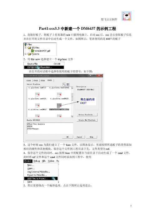
Part1:ccs3.3中新建一个DM6437的示例工程1、连接好板子,将板子上仿真器的usb口插到电脑上,启动ccs后,ccs会去获取板子信息并在打开的文件目录中自动生成一个文件,如图所示:笔者使用的是6437的板子2、用file-new选择建立一个dsp/bios文件在打开的对话框中选择你使用的板子的型号,如下图:3、这个时候ccs为我们建立了一个bios文件,以图表显示,里面按照所选板子的类型添加相应的硬件和其他模块。
保存这个文件到工程目录下先,文件类型为tcf。
4、保存这个文件的同时,ccs按照bios中的配置在当前目录下自动生成了一个cmd文件。
此时将tcf文件和这个cmd文件同时添加到工程中,使用5、然后需要修改一个编译选项,点击下图所示选项进去:6、打开后在编译选项对话框总会看到一个命令行,其中最后一句是-mv6400,因为用的是6467的板子,所以这个选项要修改成-mv64+;否则编译会报错:编译选项不正确;但并非所有类型的板子都要改,这个只针对型号为64+的板子。
7、file-new-source file建立一个c源文件,保存并加入到工程中。
以下是示例程序:#include <std.h>#include <string.h>#include <stdio.h>Int main(Int argc, String argv[])//main函数的类型必须这样写{unsigned int i;unsigned int sum=0;for(i = 0; i<=100; i++ ){sum += i;}printf("the sum = %d .\n",sum);printf("the program run over!\n");printf("the program run over!\n");}注意:1)如果想要printf正确输出信息,需要添加对应平台的rts64plus.lib文件。
DM6467 开发板 入门(第二版)

之士官方 DM6467 参考资料— 原厂DM6467 开发板 入门指南(英文影印版)本手册详细介绍了DM6467开发板的软件、硬件情况,详细阅读本手册您将可以了解到:硬件如何驳接、DM6467 EVM的设置、怎样连接到一个控制台、怎样运行一个演示软件、怎样启动独立演示程序、如何启动编码+解码演示程序、如何运行网络演示程序、如何安装Linux 、自己编译内核等。
在您使用本手册的过程中有任何技术问题或需要帮助,请联系技术支持:support@ 之士DM6467优惠促销中,请联系销售: sales@更多信息请访问DM6467专题网站:IMPORTANT NOTICETexas Instruments Incorporated and its subsidiaries (TI) reserve the right to make corrections, modifications, enhancements, improvements, and other changes to its products and services at any time and to discontinue any product or service without notice. Customers should obtain the latest relevant information before placing orders and should verify that such information is current and complete. All products are sold subject to TI's terms and conditions of sale supplied at the time of order acknowledgment.TI warrants performance of its hardware products to the specifications applicable at the time of sale in accordance with TI's standard warranty. Testing and other quality control techniques are used to the extent TI deems necessary to support this warranty. Except where mandated by government requirements, testing of all parameters of each product is not necessarily performed.TI assumes no liability for applications assistance or customer product design. Customers are responsible for their products and applications using TI components. To minimize the risks associated with customer products and applications, customers should provide adequate design and operating safeguards.TI does not warrant or represent that any license, either express or implied, is granted under any TI patent right, copyright, mask work right, or other TI intellectual property right relating to any combination, machine, or process in which TI products or services are used. Information published by TI regarding third-party products or services does not constitute a license from TI to use such products or services or a warranty or endorsement thereof. Use of such information may require a license from a third party under the patents or other intellectual property of the third party, or a license from TI under the patents or other intellectual property of TI.Reproduction of information in TI data books or data sheets is permissible only if reproduction is without alteration and is accompanied by all associated warranties, conditions, limitations, and notices. Reproduction of this infor-mation with alteration is an unfair and deceptive business practice. TI is not responsible or liable for such altered documentation.Resale of TI products or services with statements different from or beyond the parameters stated by TI for that product or service voids all express and any implied warranties for the associated TI product or service and is an unfair and deceptive business practice. TI is not responsible or liable for any such statements.Following are URLs where you can obtain information on other Texas Instruments products and application solu-tions:Products ApplicationsAmplifiers Audio /audioData Converters Automotive /automotiveDSP Broadband /broadband Interface Digital Control /digitalcontrol Logic Military /militaryPower Mgmt Optical Networking /opticalnetwork Microcontrollers Security /securityLow Power Wireless /lpw Telephony /telephonyVideo & Imaging /videoWireless /wireless Mailing Address:Texas InstrumentsPost Office Box 655303 Dallas, Texas 75265Copyright © 2008, Texas Instruments IncorporatedEVALUATION BOARD/KIT IMPORTANT NOTICETexas Instruments (TI) provides the enclosed product(s) under the following conditions:This evaluation board/kit is intended for use for ENGINEERING DEVELOPMENT, DEMON-STRATION, OR EVALUATION PURPOSES ONLY and is not considered by TI to be a finished end-product fit for general consumer use. Persons handling the product(s) must have electronics training and observe good engineering practice standards. As such, the goods being provided are not intended to be complete in terms of required design-, marketing-, and/or manufacturing-related protective considerations, including product safety and environmental measures typically found in end products that incorporate such semiconductor components or circuit boards. This evaluation board/kit does not fall within the scope of the European Union directives regarding electromagnetic compatibility, restricted substances (RoHS), recycling (WEEE), FCC, CE or UL, and therefore may not meet the technical requirements of these directives or other related directives.Should this evaluation board/kit not meet the specifications indicated in the User's Guide, the board/kit may be returned within 30 days from the date of delivery for a full refund. THE FORE-GOING WARRANTY IS THE EXCLUSIVE WARRANTY MADE BY SELLER TO BUYER AND IS IN LIEU OF ALL OTHER WARRANTIES, EXPRESSED, IMPLIED, OR STATUTORY, IN-CLUDING ANY WARRANTY OF MERCHANTABILITY OR FITNESS FOR ANY PARTICULAR PURPOSE.The user assumes all responsibility and liability for proper and safe handling of the goods. Further, the user indemnifies TI from all claims arising from the handling or use of the goods. Due to the open construction of the product, it is the user's responsibility to take any and all appropriate precautions with regard to electrostatic discharge.EXCEPT TO THE EXTENT OF THE INDEMNITY SET FORTH ABOVE, NEITHER PARTY SHALL BE LIABLE TO THE OTHER FOR ANY INDIRECT, SPECIAL, INCIDENTAL, OR CON-SEQUENTIAL DAMAGES.TI currently deals with a variety of customers for products, and therefore our arrangement with the user is not exclusive.TI assumes no liability for applications assistance, customer product design, software performance, or infringement of patents or services described herein.Please read the User's Guide and, specifically, the Warnings and Restrictions notice in the User's Guide prior to handling the product. This notice contains important safety information about temperatures and voltages. For additional information on TI's environmental and/or safety pro-grams, please contact the TI application engineer or visit /esh.No license is granted under any patent right or other intellectual property right of TI covering or relating to any machine, process, or combination in which such TI products or services might be or are used.Mailing Address:Texas InstrumentsPost Office Box 655303Dallas, Texas 75265Copyright © 2008, Texas Instruments IncorporatedFCC WarningThis evaluation board/kit is intended for use for ENGINEERING DEVELOPMENT, DEMON-STRATION, OR EVALUATION PURPOSES ONLY and is not considered by TI to be a finished end-product fit for general consumer use. It generates, uses, and can radiate radio frequency energy and has not been tested for compliance with the limits of computing devices pursuant to part 15 of FCC rules, which are designed to provide reasonable protection against radio frequency interference. Operation of this equipment in other environments may cause interfer-ence with radio communications, in which case the user at his own expense will be required to take whatever measures may be required to correct this interference.PrefaceAbout This GuideThe DVEVM (Digital Video Evaluation Module) kit is an evaluationplatform that showcases the DM646x architecture and lets usersevaluate the power and performance of the DM646x as a multimediaengine.This guide gives you overview information about the board and thesoftware provided with the board. It is intended to be used as anintroductory document for the DVEVM. Other documents provide morein-depth information. See the DVEVM release notes for a complete list ofdocuments that have been included with the product.Additional Documents and ResourcesYou can use the following sources to supplement this user’s guide:❏Spectrum Digital website:/boards/evmdm6467❏TI Linux Community for DaVinci Processors:❏TI DaVinci Software Updates: /dvevmupdates❏TI DaVinci Technology Developers Wiki: ❏Codec Engine Application Developer's Guide (SPRUE67)❏Other PDF documents included with the DVEVM kit❏Section 4.11 lists documentation in the DVSDK software installation.❏SoC Analyzer Help menuvNotational ConventionsNotational ConventionsThis document uses the following conventions:❏Program listings, program examples, and interactive displays areshown in a mono-spaced font. Examples use bold for emphasis,and interactive displays use bold to distinguish commands that youenter from items that the system displays (such as prompts,command output, error messages, etc.).❏Square brackets ( [ and ] ) identify an optional parameter. If you usean optional parameter, you specify the information within thebrackets. Unless the square brackets are in a bold typeface, do notenter the brackets themselves.TrademarksThe Texas Instruments logo and Texas Array Instruments are registered trademarks of TexasInstruments. Trademarks of Texas Instrumentsinclude: TI, DaVinci, the DaVinci logo, XDS, CodeComposer, Code Composer Studio, Probe Point,Code Explorer, DSP/BIOS, RTDX, Online DSPLab, DaVinci, TMS320, TMS320C54x,TMS320C55x, TMS320C62x, TMS320C64x,TMS320C67x, TMS320C5000, andTMS320C6000.MS-DOS, Windows, and Windows NT are trademarks of MicrosoftCorporation.UNIX is a registered trademark of The Open Group in the United Statesand other countries.Linux is a registered trademark of Linus Torvalds.Solaris, SunOS, and Java are trademarks or registered trademarks ofSun Microsystems, Inc.All other brand, product names, and service names are trademarks orregistered trademarks of their respective companies or organizations.December 18, 2008viContents 1DVEVM Overview . . . . . . . . . . . . . . . . . . . . . . . . . . . . . . . . . . . . . . . . . . . . . . . . . . . . . . . . . . .1-1 This chapter introduces the DVEVM (Digital Video Evaluation Module) kit.1.1Welcome! . . . . . . . . . . . . . . . . . . . . . . . . . . . . . . . . . . . . . . . . . . . . . . . . . . . . . . . . . . . .1-21.2What’s in this Kit?. . . . . . . . . . . . . . . . . . . . . . . . . . . . . . . . . . . . . . . . . . . . . . . . . . . . . .1-21.3What’s on the Board?. . . . . . . . . . . . . . . . . . . . . . . . . . . . . . . . . . . . . . . . . . . . . . . . . . .1-31.4What’s Next? . . . . . . . . . . . . . . . . . . . . . . . . . . . . . . . . . . . . . . . . . . . . . . . . . . . . . . . . .1-4 2EVM Hardware Setup . . . . . . . . . . . . . . . . . . . . . . . . . . . . . . . . . . . . . . . . . . . . . . . . . . . . . . .2-1 This chapter tells you how to set up the EVM hardware.2.1Setting Up the Hardware . . . . . . . . . . . . . . . . . . . . . . . . . . . . . . . . . . . . . . . . . . . . . . . .2-22.2Connecting to a Console Window . . . . . . . . . . . . . . . . . . . . . . . . . . . . . . . . . . . . . . . . .2-7 3Running the Demonstration Software . . . . . . . . . . . . . . . . . . . . . . . . . . . . . . . . . . . . . . . . . .3-1 This chapter explains how to run the software demos provided with the DVEVM kit.3.1Default Boot Configuration. . . . . . . . . . . . . . . . . . . . . . . . . . . . . . . . . . . . . . . . . . . . . . .3-23.2Starting the Standalone Demos . . . . . . . . . . . . . . . . . . . . . . . . . . . . . . . . . . . . . . . . . . .3-23.3Running the Standalone Demos. . . . . . . . . . . . . . . . . . . . . . . . . . . . . . . . . . . . . . . . . . .3-43.3.1Shutting Down the Demos . . . . . . . . . . . . . . . . . . . . . . . . . . . . . . . . . . . . . . .3-53.3.2About the Encode + Decode Demo . . . . . . . . . . . . . . . . . . . . . . . . . . . . . . . .3-63.3.3About the Encode Demo . . . . . . . . . . . . . . . . . . . . . . . . . . . . . . . . . . . . . . . .3-73.3.4About the Decode Demo . . . . . . . . . . . . . . . . . . . . . . . . . . . . . . . . . . . . . . . .3-93.3.5About the Third Party Menu. . . . . . . . . . . . . . . . . . . . . . . . . . . . . . . . . . . . .3-103.4Running the Demos from the Command Line . . . . . . . . . . . . . . . . . . . . . . . . . . . . . . .3-103.5Running the Network Demo. . . . . . . . . . . . . . . . . . . . . . . . . . . . . . . . . . . . . . . . . . . . .3-12 4DVEVM Software Setup . . . . . . . . . . . . . . . . . . . . . . . . . . . . . . . . . . . . . . . . . . . . . . . . . . . . .4-1 This chapter explains how to use the software provided with the DVEVM kit.4.1Software Overview. . . . . . . . . . . . . . . . . . . . . . . . . . . . . . . . . . . . . . . . . . . . . . . . . . . . .4-24.1.1Command Prompts in This Guide . . . . . . . . . . . . . . . . . . . . . . . . . . . . . . . . .4-34.1.2Software Components . . . . . . . . . . . . . . . . . . . . . . . . . . . . . . . . . . . . . . . . . .4-44.2Preparing to Install . . . . . . . . . . . . . . . . . . . . . . . . . . . . . . . . . . . . . . . . . . . . . . . . . . . . .4-54.3Installing the Software . . . . . . . . . . . . . . . . . . . . . . . . . . . . . . . . . . . . . . . . . . . . . . . . . .4-54.3.1Installing the Target Linux Software. . . . . . . . . . . . . . . . . . . . . . . . . . . . . . . .4-64.3.2Installing the DVSDK Software. . . . . . . . . . . . . . . . . . . . . . . . . . . . . . . . . . . .4-74.3.3Installing the A/V Demo Files. . . . . . . . . . . . . . . . . . . . . . . . . . . . . . . . . . . . .4-84.3.4Installing the SoC Analyzer . . . . . . . . . . . . . . . . . . . . . . . . . . . . . . . . . . . . . .4-9viiContentsviii4.3.5Exporting a Shared File System for Target Access . . . . . . . . . . . . . . . . . . . 4-94.3.6Testing the Shared File System . . . . . . . . . . . . . . . . . . . . . . . . . . . . . . . . . 4-114.3.7Notes on Using Evaluation/Production Codecs . . . . . . . . . . . . . . . . . . . . . 4-12 4.4Setting Up the Build/Development Environment. . . . . . . . . . . . . . . . . . . . . . . . . . . . . 4-124.4.1Writing a Simple Program and Running it on the EVM. . . . . . . . . . . . . . . . 4-13 4.5Building a New Linux Kernel. . . . . . . . . . . . . . . . . . . . . . . . . . . . . . . . . . . . . . . . . . . . 4-13 4.6Rebuilding the DVEVM Software for the Target . . . . . . . . . . . . . . . . . . . . . . . . . . . . . 4-15 4.7Booting the New Linux Kernel. . . . . . . . . . . . . . . . . . . . . . . . . . . . . . . . . . . . . . . . . . . 4-16 4.8Testing the Build Environment . . . . . . . . . . . . . . . . . . . . . . . . . . . . . . . . . . . . . . . . . . 4-17 4.9Using the Digital Video Test Bench (DVTB) . . . . . . . . . . . . . . . . . . . . . . . . . . . . . . . . 4-18 4.10Running The SoC Analyzer. . . . . . . . . . . . . . . . . . . . . . . . . . . . . . . . . . . . . . . . . . . . . 4-19 4.11Documentation for DSP-Side Development . . . . . . . . . . . . . . . . . . . . . . . . . . . . . . . . 4-20A Additional Procedures . . . . . . . . . . . . . . . . . . . . . . . . . . . . . . . . . . . . . . . . . . . . . . . . . . . . . .A-1This appendix describes optional procedures you may use depending on your setup and specific needs.A.1Putting Demo Applications in the Third-Party Menu. . . . . . . . . . . . . . . . . . . . . . . . . . . . . . . . . . . A-2A.2Setting Up a TFTP Server . . . . . . . . . . . . . . . . . . . . . . . . . . . . . . . . . . . . . . . . . . . . . . . . . . . . . . A-4A.3Alternate Boot Methods . . . . . . . . . . . . . . . . . . . . . . . . . . . . . . . . . . . . . . . . . . . . . . . . . . . . . . . . A-5A.4Updating and Restoring the Bootloaders. . . . . . . . . . . . . . . . . . . . . . . . . . . . . . . . . . . . . . . . . . . A-7A.5Installing uImage in NAND Flash. . . . . . . . . . . . . . . . . . . . . . . . . . . . . . . . . . . . . . . . . . . . . . . . . A-9A.6Rebuilding DSP/BIOS Link. . . . . . . . . . . . . . . . . . . . . . . . . . . . . . . . . . . . . . . . . . . . . . . . . . . . . A-10A.7Restoring and Updating the EVM Hard Disk Drive. . . . . . . . . . . . . . . . . . . . . . . . . . . . . . . . . . . A-11DVEVM Overview This chapter introduces the DVEVM (Digital Video Evaluation Module) kit.Topic Page 1.1Welcome! . . . . . . . . . . . . . . . . . . . . . . . . . . . . . . . . . . . . . . . . . . . . . . . 1–2 1.2What’s in this Kit?. . . . . . . . . . . . . . . . . . . . . . . . . . . . . . . . . . . . . . . . 1–2 1.3What’s on the Board?. . . . . . . . . . . . . . . . . . . . . . . . . . . . . . . . . . . . . 1–3 1.4What’s Next? . . . . . . . . . . . . . . . . . . . . . . . . . . . . . . . . . . . . . . . . . . . . 1–41-1Welcome!1-21.1Welcome!Your new DVEVM (Digital Video EvaluationModule) kit will allow you to evaluate TI’s newDaVinci TM Technology and the DM646xarchitecture.This technology brings together system-solutioncomponents tailored for efficient and compellingdigital video and audio.1.2What’s in this Kit?Your DVEVM kit contains the following hardware items. Section 2.1,Setting Up the Hardware tells how to connect these components.❏EVM Board . This board contains a DaVinci TMS320DM6467 dual-core device with an ARM9 and C64+ DSP for development ofapplications that use both a general-purpose processor and an accelerated DSP processor.❏Hard Disk Drive . The hard drive provided with the EVM is a 2.5"Spinpoint drive with 40 GB of storage. The drive speed in 5400 RPM and it has an 8MB cache. The drive is an Ultra ATA 66/100/133 IDE.Software has been preloaded on this EVM board’s hard disk drive.❏IR Remote Control . This universal remote control is included to provide a user interface to the demo applications.❏Cables. Cables used to connect the EVM board to peripheral devices and to a host Linux workstation used for development are provided in the kit.The DVEVM kit also comes with the following software. Information about how to use the software components is provided in Chapter 4.❏DaVinci Digital Video Evaluation Kit.❏TI DaVinci Demonstration Version of MontaVista Linux Pro v5.0Target ❏TI DaVinci Demonstration Version of MontaVista Linux Pro v5.0Tools ❏A/V Media Clips ❏Spectrum Digital EVM Tools ❏SoC AnalyzerWhat’s on the Board?1.3What’s on the Board?The EVM comes loaded with peripherals your multimedia applicationsmay need to make use of. The hard drive on the board also comes pre-loaded with demonstration software. The following block diagram showsthe major hardware components.Figure 1–1 EVM Hardware Block DiagramFor more information about the EVM hardware, see the DaVinci EVMwebsite at /boards/evmdm6467.DVEVM Overview1-3What’s Next?1-41.4What’s Next?To get started evaluating the DVEVM kit and developing applications for the DM646x, begin by using this Getting Started guide. It will step you through connecting the hardware, testing the software, and beginning to develop applications.When you are ready for more information about DaVinci Technology and the DM646x architecture, see the following:❏Spectrum Digital website:/boards/evmdm6467❏TI Linux Community for DaVinci Processors: ❏TI DaVinci Software Updates: /dvevmupdates ❏TI DaVinci Technology Developers Wiki: ❏Codec Engine Application Developer's Guide (SPRUE67)❏Other PDF documents included with the DVEVM kit❏Section 4.11 lists documentation in the DVSDK software installation.❏SoC Analyzer Help menuEVM Hardware SetupThis chapter tells you how to set up the EVM hardware.Topic Page 2.1Setting Up the Hardware. . . . . . . . . . . . . . . . . . . . . . . . . . . . . . . . . . . 2–2 2.2Connecting to a Console Window . . . . . . . . . . . . . . . . . . . . . . . . . . . 2–72-1Setting Up the Hardware2-22.1Setting Up the HardwareTo set up the hardware provided with the EVM, use the steps in the sections that follow. You may skip sections if you do not need to access a particular peripheral. For example, if you do not need to use the serial cable, skip that section.1)The EVM is sensitive to static discharges. Usea grounding strap or other device to prevent damaging the board.Be sure to connect communication cables before applying power to any equipment.2)Verify that the EVM board’s EMU0/1 select switch (S1) is setcorrectly. The settings shown here enable both ARM and DSP JTAGfor emulation debugging.Setting Up the HardwareEVM Hardware Setup 2-33)Verify that the EVM board’s SW3 boot/muxing configuration switch iscorrectly set. The BM1, BM2, and BM3 switches should be set to On.These switch settings, which are shown in the following figure,enable the following:■SPI boot mode■EMIF A is 8-bit data bus for CS2■PCI pin multiplexing enabled on DM6467■DSP is booted via ARM processor4)Connect the Ethernet cable to the Ethernet port on the EVM boardand to an Ethernet network port. Note that the U-Boot bootargs mustinclude "ip=dhcp" to enable the network connection.Setting Up the Hardware2-45)Connect a video source (for example, a camera or DVD player) to thecomponent input video connectors (J1, J2, J3). Note: To run the demos described in Chapter 3, you will need to have an HD (720p) video source connected to the EVM board's component input connectors.6)Connect your video display to the EVM board’s component outputvideo connectors (J10, J11 and J12) using the component cables included with the DVEVM kit. Note: To run the demos described in Chapter 3, you will need to have an HD display connected to the EVMboard's component output connectors.Setting Up the HardwareEVM Hardware Setup 2-57)Connect an audio speaker to the headphone connector (P4).8)Connect an audio source to the microphone connector (P8).Setting Up the Hardware2-69)If you plan to use the UART port for a console window, connect theRS-232 null modem cable to the EVM UART port (P1) and to the COM port of your host workstation.10)Power on your video input and output devices.11)Connect the power cable to the EVM power jack on the board. To beESD safe, plug in the other end of the power cable only after you have connected the power cord to the board. Then turn on the board.12)The initial screen of the demo software should be displayed on yourvideo output device. Use the IR remote to run the software asdescribed in Chapter 3.Connecting to a Console Window 2.2Connecting to a Console WindowYou can open a console window that allows you to watch and interruptEVM boot messages by following these steps:1)Connect a serial cable between the serial port on the EVM and theserial port (for example, COM1) on a PC.2)Run a terminal session (such as Minicom on Linux or HyperTerminalon Windows) on the workstation and configure it to connect to thatserial port with the following characteristics:■Bits per Second: 115200■Data Bits: 8■Parity: None■Stop Bits: 1■Flow Control: None3)When you power on the EVM, you will see boot sequence messages.You can press a key to interrupt the boot sequence and typecommands in the U-Boot command shell. In this guide, commands tobe typed in the U-Boot shell are indicated by anEVM # prompt.EVM Hardware Setup2-72-8Running the Demonstration Software This chapter explains how to run the software demos provided with theDVEVM kit.Topic Page3.1Default Boot Configuration. . . . . . . . . . . . . . . . . . . . . . . . . . . . . . . . . 3–23.2Starting the Standalone Demos. . . . . . . . . . . . . . . . . . . . . . . . . . . . . 3–23.3Running the Standalone Demos . . . . . . . . . . . . . . . . . . . . . . . . . . . . 3–43.4Running the Demos from the Command Line . . . . . . . . . . . . . . . . 3–103.5Running the Network Demo . . . . . . . . . . . . . . . . . . . . . . . . . . . . . . . 3–123-1Default Boot Configuration 3-23.1Default Boot ConfigurationOut of the box, the EVM boots from flash and starts the demos automatically after a few seconds when you power up the board. It does not require an NFS mount or a TFTP server to run the standard demos. Note: The default U-Boot bootargs definition sets "ip=off", which disables the Ethernet connection.The out-of-the-box boot parameters are listed in Section A.3.1. The following are alternate ways you may want to boot the board:❏TFTP boot with hard drive file system (Section A.3.2)❏Flash boot with NFS file system (Section A.3.3)❏TFTP boot with NFS file system (Section A.3.4)To abort the standard boot, press any key in the console window (see Section 2.2). Also see Section A.3, Alternate Boot Methods if you want to change the boot configuration.3.2Starting the Standalone DemosWhen you connect the EVM hardware, the pre-loaded examples run automatically on the display connected to the EVM board's component output connectors, using a 720p (HD) video source connected to the component input connectors. These examples encode and decode audio, video, and speech. There are two ways to use the demos:❏Standalone. This is the default power-on mode. The demos run automatically with no connection to a workstation in the default bootconfiguration. This is the mode documented in the rest of this chapter.The standalone demo was set up by the DVSDK, which copies the file /examples/dvevmdemo to the directory /etc/rc.d/init.d (the central repository for startup scripts). This file is symbolically linked to /etc/rc.d/rc3id/S88demo. When the board boots up and enters runlevel 3, this file is executed to start the demo web server and the demo interface.❏Command line. Once you have connected the EVM to a workstation and installed the necessary software (as described in Section 4.3.1,Installing the Target Linux Software ), you can run the demos from the board’s Linux command line. For further information on running the demos from the command line, see the demo documentation that is linked to by the DVSDK release notes.Note: When you run the demos from the command line, make sure the interface process used by the standalone mode demos is notStarting the Standalone DemosRunning the Demonstration Software 3-3running. Otherwise you will see error messages raised when device drivers fail to open.Once the EVM board has booted, the displayshould show a picture of the remote control.You use the IR remote to control the demos.The order of the buttons on the actual remotemay be different from the picture; if yourremote looks different, find the buttons withthe same labels on your remote.To use the demos in standalone mode, followthese steps:1)Check to make sure the batteries areinstalled in your IR remote.2)Make sure an HD (720p) video source isconnected to the EVM board'scomponent input connectors. Also makesure an HD display is connected to theEVM board's component outputconnectors.Note: The demos do not currentlysupport composite video output.3)The initial screen shows a diagram of theIR remote, which you use to run thestandalone demos. Take a minute to lookat the functions of the various buttons.4)Since this is a universal remote, you mayneed to set it to use the codes necessaryto run the DVEVM demos. To do this, holddown the "Code Search" button until thered light on the remote stays lit. Thenpress the "DVD" button and enter "0020"as the code.5)If you accidentally put the remote in TV or some other mode, press"DVD" to return the remote to the correct mode.6)If the remote does not accept the DVD+0020 code, do a full reset byremoving the batteries, pressing the Power button for at least a minute, then reinserting the batteries. Then program the remote as in Step 3.。
达芬奇技术简单介绍
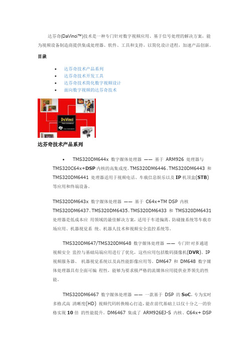
达芬奇(DaVinci™)技术是一种专门针对数字视频应用、基于信号处理的解决方案,能为视频设备制造商提供集成处理器、软件、工具和支持,以简化设计进程,加速产品创新。
目录∙达芬奇技术产品系列∙达芬奇技术开发工具∙达芬奇技术简化数字视频设计∙面向数字视频的达芬奇技术达芬奇技术产品系列∙TMS320DM644x 数字媒体处理器——基于ARM926 处理器与TMS320C64x+DSP内核的高集成度。
TMS320DM6446、TMS320DM6443 和TMS320DM6441 处理器适用于视频电话、车载信息娱乐以及IP机顶盒(STB)等应用和终端设备。
TMS320DM643x 数字媒体处理器——基于C64x+TM DSP 内核TMS320DM6437、TMS320DM6435、TMS320DM6433 和TMS320DM6431 处理器是低成本应用领域的最佳解决方案,适用于车道偏离、防碰撞系统等车载市场应用、机器视觉系统、机器人技术和视频安全监控系统等。
TMS320DM647/TMS320DM648 数字媒体处理器——专门针对多通道视频安全监控与基础局端应用进行了优化,这些应用包括数码摄像机(DVR)、IP 视频服务器、机器视觉系统以及高性能影像应用等。
DM647 和DM648 数字媒体处理器具有全面可编程性,能够为要求极严格的流媒体应用提供业界领先的性能。
TMS320DM6467 数字媒体处理器——一款基于DSP 的SoC,专为实时多格式高清晰度(HD) 视频代码转换精心打造,能在前代基础上以仅十分之一的价格实现10倍的性能提升。
DM6467 集成了ARM926EJ-S 内核、C64x+ DSP内核,并采用高清视频/影像协处理器(HD-VICP)、视频数据转换引擎与目标视频端口接口。
DM6467 可充分满足HD 转码方面的市场要求,非常适用于企业及个人市场的媒体网关、多点控制单元、数字媒体适配器、数字视频服务器以及安全监控市场记录器与IP 机顶盒等应用。
SEED_VPM6467硬件用户指南
5
参考资料:
TMS320DM6467 Digital Media System-on-Chip datasheet(tms320dm6467.pdf):介绍 TMS320DM6467 CPU 架构及其外设资源。 TMS320DM646x DMSoC ARM Subsystem Reference Guide(spruep9a.pdf) :介 绍 TMS320DM646x 系统的 ARM 子系统。 TMS320DM646x DMSoc DSP Subsystem Reference Guide(spruep8.pdf) :介绍 TMS320DM646x 系统的 DSP 子系统。 TMS320DM646x DMSoC Peripherals Overview Reference Guide (Rev.A ) (sprueq0a.pdf): 介绍 TMS320DM646x 系统的概述以及各个外设模块。 TMS320DM646x DMSoC Video Port Interface (VPIF) User's Guide ( spruer 9_ a .pdf) : 介 绍 TMS320DM646x 系统的 VPIF 模块。 TMS320DM646x DMSoc DDR2 Memory Controller User’Guide(sprueq4a.pdf) : 介 绍 TMS320DM646x 系统的 DDR2 存储器控制器模块。 TMS320DM646x DMSoc Asynchronous External Memory Interface User’s Guide (sprueq7a.pdf) :介 绍 TMS320DM646x 系统的异步外部存储器接口模块。 TMS320DM646x DMSoc ATA Controller User’s Guide ( sprueq3.pdf ) :介绍 TMS320DM646x 系统的硬盘控制器模块。 TMS320DM646x DMSoc Enhanced Direct Memory Access Controller User’s Guide (sprueq5a.pdf) :介 绍 TMS320DM646x 系统的增强型 DMA 控制器模块。 TMS320DM646x DMSoC Multichannel Audio Serial Port (McASP) User's Guide (Rev. B)(spruer1b.pdf) :介绍 TMS320DM646x 系统的音频串口模块。 TMS320DM646x DMSoC EMAC/MDIO Module User's Guide (sprueq6.pdf) : 介 绍 TMS320DM646x 系统的 EMAC 和 MDIO 网络连接模块。 TMS320DM646x DMSoC General-Purpose GPIO User's Guide(sprueq8.pdf) :介绍 TMS646x 系统的 GPIO 资源与使用。
达芬奇软件架构
Davinci架构的由三个部分组成,即:codecs,servers,apps(算法,算法服务器,应用。
)codecs是不能单独成为程序的,它是以库的形式提供给,servers,apps。
servers是dsp可以运行的程序(包括操作系统)。
Apps是arm端linux操作系统下的一个应用程序。
下面分别讲解这三个部分的构成。
1.codecs进入jerry@jerry-laptop:~/dvsdk_3_00_01_42/codec_engine_2_24/examples/ti/sd o/ce/examples/codecs$ lsauddec1_copy imgdec1_copy package.xdc universal_copy videnc1_copy auddec1_ires imgdec_copy scale vidanalytics_copy videnc_copyauddec_copy imgenc1_copy sphdec1_copy viddec1_copy vidtranscode_copy audenc1_copy imgenc_copy sphdec_copy viddec2_copyaudenc_copy makefile sphenc1_copy viddec2split_copyg711 package sphenc_copy viddec_copy我们可以看到已经有很多算法了。
我们看其中一个:jerry@jerry-laptop:~/dvsdk_3_00_01_42/codec_engine_2_24/examples/ti/sd o/ce/examples/codecs/viddec_copy$ lslib package.bld viddec_copy.c VIDDEC_COPY.xdcmakefile package.xdc viddec_copy_ti.h VIDDEC_COPY.xspackage package.xs viddec_copy_ti_priv.h可以看出,一个算法有1.makefile文件,我们编译算法执行make的时候就是使用的makefile.2.viddec_copy_ti_priv.h,viddec_copy_ti.h,viddec_copy_ti.h是算法的源代码。
基于TMS320DM6467的视频采集系统设计
【 e od 】v e atr;V L ;D 4 7 poesr T P 8 dcd r V I nefc K y w r s i o cpue 4 2 M6 6 rcso; V 5 eo e; PF it ae d 1 5 r
0 引 言
多媒体技术的飞速发展激发 了人们对视频信息的需
完成 了接 口电路 设 计 , 开发 了多通 道 视 频端 口和 基 于 V L 的 D V ni 频接 口驱 动程 序 , 后通 过 V I 口将采 集到 的视 频 帧 送 42 a ic视 最 PF接
入 L D显 示 设备 进 行 显 示 。 C
【 关键词 】视 频采集; 4 2 D 4 7 V L ; M6 6 处理器 ;V 5 5 译 码器 ; PF 口 T P 18 V I接 【 中图分类号 】T 9 1T 3 9 N 1 ; P 1 【 文献标 识码 】A
【 sr c】A hn e ra—i e v e atr ss m w t T P 8 dcd ri i pe ne . aie D 4 7 dg a m da Abtat n 8ca nl elt i o cpue yt i V 5 eo e s m l td D vni M6 6 iil e i m d e h 1 5 me t
De i n f Vi o s g o de Ca ur Sy t m Ba e o TM S3 O pt e se s d n 2 DM 6 67 4
W EN W u,W U Yo g,ZHANG i。 n Je
l.C ogig I om t n Tcnl y D s nn o,l . hn q g U i rt o ot ad Tl o u i t n,C og ig 4 12 ,C ia 】 hn q n r ai ehoo ei i C . 2 ,C og i nv s) fP s n e cmm nc i s hn q 0 1 1 hn; n f o g g g d n e i s e ao n 2 ntueo pld Cmmu i tn Tcr o y hn qn n e i f P s n e cm nct n,C og i 0 0 5 hn ) .Isit f A p& o t n ai ehml ,C og i U i rt o ot a d Tl o mu i i c o g g v sy s e ao s hn qn 4 0 6,C ia g
DaVinci技术DM6467平台算法的开发
随着信息技术的飞速发展 , 视频通信因其直观性 、
可靠 性等 优点 , 已逐 步 走 进 人们 的 生活 , 为新 的应 用 成 需求 热 点 。但 因其 数 据 的海量 性 , 使得 信息 的存储 和传
发和封 装并配置其 算法服务 器 ,在 A M端 配置 R 其算 法引擎,然后 通过 中间层软件 Cd cE gn oe nie
系统( l2 2 5 16 1 国家 自然科 学基金 : 1c 6 1 130 ) 利用认知无 线电技 术提 高下
一
代 移 动 通 信 容 量 的 算 法 研 究 (0 7 0 7 6823 )
固
一 … 一…~ …
…
…
…
…
…
…
…
M粼
N YEMN l oL M 】 FE U 啪 T0 c
a he e c iv .
达芬奇技 术算法的软件 开发
达芬奇 技 术平 台具 有 典 型的 A RM+ S 布 式 异 D P分
构 体 系结 构 , 作 系统 为 D PB O 操 S / I S的 D P端 , S 主要 负
K y e wo d : D Vic T h oo ,DM sa d r rs a n i e n lg x c y tn ad
调 用其 AP 函 数 采 实现 执 行 的 。 l
输具有很大的困难 ,成 为阻碍人类有效获得 和使用视
频 信息 的瓶 颈 。为 了解决 这一 难题 , 多媒 体技 术应 用使
关键词 :达芬奇技 术 ,D x M标 准算法 ,算 法服 务 器。 算法引擎
Ab t c : T e rmoe ag rh sr t a h e t loi m o DM6 6 t f 47
基于VC的LTE4G通信modem软件仿真平台的搭建
基于VC的LTE4G通信modem软件仿真平台的搭建郭梦霞【摘要】This paper describes the simulation platform to build 4G wireless describes the architecture and processing systems, and describes the relevant module, as well as the interaction between modules. Focuses on the inter-module communication media-using the ring buffer, so that data can be securely transmitted between the modules. The ring buffer has a small footprint, easy to manage, etc., can be widely applied to other common platforms. Also, the simulation platform using C language development, programming is simple and easy to develop a successor.And platform portability, and easy migration development on different operating systems. At the same time, the simulation platform uses a modular design, with good scalability, hardware logic by modifying the code stub code, can be used on different chip development platform.%文中阐述了4G无线仿真平台的搭建,描述了系统的架构和处理流程,并介绍了相关模块,以及模块间的交互过程。
- 1、下载文档前请自行甄别文档内容的完整性,平台不提供额外的编辑、内容补充、找答案等附加服务。
- 2、"仅部分预览"的文档,不可在线预览部分如存在完整性等问题,可反馈申请退款(可完整预览的文档不适用该条件!)。
- 3、如文档侵犯您的权益,请联系客服反馈,我们会尽快为您处理(人工客服工作时间:9:00-18:30)。
达芬奇 DM6467 评估板 系统软件平台构 建 方 法Revision Table Date Rev. Author Content of revision 1.0 2009-09-01 Andy,LIU OriginalApproval1 系统介绍.......................................................................................................................................4 2 开发环境的建立...........................................................................................................................4 3 网络文件系统的建立...................................................................................................................5 4 tftp 服务的建立 .............................................................................................................................5 5 UBOOT 的使用.............................................................................................................................6 6 启动方式说明...............................................................................................................................8 7 硬盘的恢复...................................................................................................................................9 8 uboot 和 kernel 的编译..................................................................................................................9 9 在 nand flash 上使用 uboot 烧写 kernel .....................................................................................101 系统介绍建立 DM6467 开发平台是进行软件研发的基础,DM6467 EVM 以 LINUX 为 操作系统,文件系统可以放置在 FLASH 中,也可以放置在硬盘中,可以根据具 体的应用进行选取。
本文告诉用户如何构建自己的 DM6467 的开发平台。
2 开发环境的建立先建立 linux 开发环境,如 redhat,然后准备好以下文件: dvsdk_setuplinux_#_#_#_#.bin mvl_4_0_1_demo_lsp_setuplinux_#_#_#_#.bin xdc_setuplinux_#_#_#_#.bin bios_setuplinux_#_#_#_#.bin TI-C6x-CGT-v#.#.#.#.bin data.tar.gz SoCAnalyzer_#.#.#.#.exe 将上述四个文件拷贝到/tmp 路径下。
确认刚刚安装好的linux的X图像显示没有问题,并且建立DISPLAY的环境变 量,例如: csh下命令: host $ setenv DISPLAY cnabc0314159d1:0 ksh下命令: host $ export DISPLAY=cnabc0314159d1:0 第一步:进入/tmp 路径下,依次执行下面两个程序: host $ ./mvl_4_0_1_demo_sys_setuplinux.bin host $ ./mvl_4_0_1_demo_target_setuplinux.bin host $ ./mvl_4_0_1_demo_lsp_setuplinux_#_#_#_#.bin 软件会开始自解压过程,其安装的默认路径为/opt。
第二步:进入/opt/mv_pro_4.0.1,会发现有以下两个文件: mvltools4.0.1-no-target.tar.gz mvl4.0.1-target_path.tar.gz DaVinciLSP#_#_#_#.tar.gz 将DaVinciLSP#_#_#_#.tar.gz也拷贝到/opt/mv_pro_4.0.1下, 然后开始按照 下面的方式进行自解压: host $ tar zxf mvltools4.0.1-no-target.tar.gz host $ tar zxf mvl4.0.1-target_path.tar.gz host $ tar zxf DaVinciLSP#_#_#_#.tar.gz 第三步:进入/tmp 路径下,执行下面命令: host $ ./dvsdk_setuplinux_#_#_#_#.bin软件会开始自解压过程,其安装的默认路径为/opt。
最后,在/root 下,以 root 身份打开.bashrc,设置以下路径: PATH="/opt/mv_pro_4.0.1/montavista/pro/devkit/arm/v5t_le/bin: /opt/mv_pro_4.0.1/montavista/pro/bin: /opt/mv_pro_4.0.1/montavista/common/bin:$PATH" 设置好路径后,重新启动 LINUX,开发环境安装完成。
3 网络文件系统的建立在研发中,为了节省开发时间,常常用到网络文件系统,本节以/root/armfs 为网络文件系统路径,PC 机的 IP 为 192.168.0.60,DM6467 EVM 板的地址为 192.168.0.32 为例子,建立网络文件系统的开发环境。
第一步:在/root 下建立 armfs 目录,作为网络文件系统的根目录。
第二步:执行以下命令: host $ cp -a /opt/mv_pro_4.0/montavista/pro/devkit/arm/v5t_le/target/* /root/armfs 将网络系统所需要的文件拷贝到/root/armfs下, 拷贝可能要花比较长的时间, 拷贝完成后,可以和/opt/mv_pro_4.0/montavista/pro/devkit/arm/v5t_le/target路 径下的文件对照一下,检查是否正确。
第三步:设置/etc/exports文件,输入 /root/armfs *(rw,no_root_squash,no_all_squash,sync) 然后保存推出。
第四步:打开网络文件系统服务,执行下面命令: host $service nfs restart。
第五步:对DM6467 EVM正确上电后,进入uboot,设置以下变量: TirDavinci_EVM# setenv ipaddr 192.168.0.32 TirDavinci_EVM# setenv nfsroot 192.168.0.60:/root/armfs TirDavinci_EVM# setenv bootargs console=ttyS0,115200n8 noinitrd rw ip=192.168.0.32:192.168.0.60 root=/dev/nfs nfsroot=$(nfsroot),nolock mem=120M davincihd_capture.channel0_numbuffers=4 然后执行 boot 重新启动,如果设置正确并且 KERNEL 没有问题,网络文件 系统会正常启动,如果不能正常启动,请检查设置步骤。
4 tftp 服务的建立如果 tftp 没有安装,请安装 tftp。
第一步:修改/etc/xinetd.d/tftp 如下: service tftp { disable = nosocket_type = dgram protocol = udp wait = yes user = root server = /usr/sbin/in.tftpd server_args = -s /tftpboot -c per_source = 11 cps = 100 2 flags = IPv4 } 第二步:保存后执行如下命令: host $service iptables stop host $service xinetd restart tftp 启动完成。
第三步:对 DM6467 EVM 正确上电后,进入 uboot,设置以下变量: TirDavinci_EVM# setenv serverip 192.168.0.60 TirDavinci_EVM# setenv ipaddr 192.168.0.32 TirDavinci_EVM# setenv ethaddr ff:ff:ff:ff:ff:ff TirDavinci_EVM# tftp 0x80000200 uImage TirDavinci_EVM# bootm 0x80000200 系统将从 192.168.0.60 机器上/tftpboot 目录下下载 uImage 到 DM6467 EVM 的 0x80000200 地址上, 然后从该地址启动 linux kernel, 文件系统从默认位 置启动,这可以用 printenv 命令看出,使 nfs 还是 hda。
5 UBOOT 的使用UBOOT 的命令可以在系统命令提示符下,通过 help 命令来获得。
下面是常 用的命名的一些简单说明。
1) bootm [addr [arg ...]] bootm 命令可以引导启动存储在内存中的程序映像。