TN8000数采箱如何安装系统模块(HSC-1812)及存储模块(SATA接口)
数采系统的软、硬件安装过程

第一节 数采系统的软、硬件安装过程1.1硬件安装1.1.1配置底层驱动程序数据采集板插到计算机主板上以后,启动计算机。
在启动过程中,计算机会有找到新硬件的提示。
如果没有,就进行手动添加新硬件。
具体步骤:开始-〉设置-〉控制面板-〉添加/删除硬件,按照提示一步一步进行。
当运行到期望安装向导做什么的时候,选择“显示已知设备驱动……”,运行下一步。
选择Texas Instrument OHCI Compliant IEEE 1394 Host Controller继续按照提示进行安装。
如果没有找到新硬件,可以利用添加新设备,设备的名称和上面的一样。
如果还是找不到的话,就只能说明计算机系统的硬件与数采系统有冲突,只能更换计算机硬件设备了。
进入设备管理器,步骤:右键单击我的电脑-〉属性-〉硬件-〉设备管理器,如果发现下图,说明总线还不能使用,要重新安装驱动。
1.1.2安装仪器驱动打开仪器,进入设备管理器系统会自动安装Test & Management devices,确认该项安装下是Agilent E8491 1394 VXI controller。
如果不是的话,要重新进行安装。
当设备管理器如上所示,说明硬件安装完成。
1.2软件安装1.2.1安装I/O Control将标记为I/O libraries for Instrument Control的光盘放入光驱,安装时安装缺省提示。
完成之后,计算机右下角任务栏会出现蓝色IO图标。
选择Auto configure,可以自动配置端口地址区段。
选择COM1和COM2,点击Remove。
再配置I-SCPI,在左边的方框内选择I-SCPI,在点击Configure,选择默认设置,单击OK,配置仪器完成。
当关闭仪器再启动后,在计算机屏幕左上角出现下图说明安装成功了。
在每次启动仪器时,仪器和电脑是否连接通,除了看仪器上面的提示,看failure灯是否亮以外,也可以看电脑仪器启动时是否有上面的图标。
(完整word版)8000后台电气系统

8000后台电气系统后台管理监控系统概述及操作方法第一讲 8000系统概述1 8000系统软件组成8000系统软件组成:操作员站、工程师站、远动站。
操作员站组成:操作员站图形系统、操作员站数据库系统、操作员站监控系统。
工程师站组成:工程师站数据库系统、录波、小电流接地选线远动站组成:数据库系统。
2 8000系统各站目录结构⏹操作员站目录结构⏹二级目录:⏹BIN 存放监控所有的执行模块⏹INI 存放所有的配置文件⏹MEDIA 存放所有的语音报警文件⏹REPORT 存放所有的报表定义文件⏹CURVE 存放所有的曲线定义文件⏹RECALL 存放事故追忆数据文件⏹LOG 存放服务器运行的日志信息⏹DATA 存放AV图形监控系统数据定义文件⏹GDATA 存放AV图形监控系统图形文件⏹CLASSLIB 存放AV图形监控系统用户类库文件⏹AVWeb 存放AV图形系统WEB发布功能组件包⏹IMAGE 存放AV图形系统所嵌入的各种外部图像资源,如位图等。
⏹DBGRID 存放DBGRID安装文件⏹主要可执行文件列表(位于Bin目录下):主要程序列表(可执行文件*.exe)文件名说明AutopVision 图形组态程序AVConfig 节点配置程序AVDataMan 测点浏览程序AVService 图形服务程序AVView 图形显示程序CbzAccident 事故追忆程序CbzAlarm 历史报警程序CbzCurve 曲线系统程序CBZDataTools 数据维护程序CbzDispatcher 实时监控程序CbzHisData 历史数护服务程序CbzMessageShow 装置报文查看程序CbzRealData 实时数服务护程序CbzReport 报表系统程序CbzTest 功能模块测试程序CMemDBBrowse 内存库浏览程序Journey 运行日志程序⏹工程师站目录结构⏹在Protect_Inf下:⏹EngTools 数据库制作文件⏹WaveAnalyze 录波分析软件⏹ProtIn8000.exe 工程师站启动软件⏹Eng8000hlp.hlp 工程师站帮助软件⏹远动站目录结构⏹正确安装后下列文件及目录存放在C:\Program Files \RTU目录下。
模块数字显示挂载系统安装指南说明书

DIGITAL DISPLAY Modular Digital Display MountInstall Guide2Warning• Please do not begin installation until you have thoroughly read and understood these instructions.• Failure to read, thoroughly understand, and follow all instructions may result in serious personal injury, property damage, or death. It is the installer’s responsibility to ensure all mounting systems are properly assembled and installed using the instructions provided.• Installation by a qualified professional is highly recommend for this product. Do not install if you have doubts regarding the effectiveness or safety of an installation method.• This product is intended for indoor use only. Use of this product outdoors may lead to product failure or personal injury. For support please call Customer Care at 866.424.4489.• Do not install if any parts are missing or defective. Do not attempt to replace with unapproved parts or materials or install without all required parts.• Before installing, ensure the supporting surface will support the combined load of the equipment and hardware, including ensuring that the wall that you plan to use will safely support four times the combined weight of the mount and your chosen display configuration.• Use of a suitable safety cables is recommended as a redundant safety measure, and may be required under local building codes.• Always use an assistant or mechanical lifting equipment to safely lift and position the equipment.• Screws must be tightly secured. Do not overtighten screws or damage may occur and product may fail.• Under no circumstance should this product be mounted to metal studs.• The manufacturer does not accept responsibility for incorrect installation.• Do not exceed the maximum load (see next page).Preparation Is KeyEvery installation is different, so the modular digital display mount provides a system that is entirely customizable to your needs. Because your install is unique, this manual addresses assembly instructions, but does not address how to select the hardware you need.To plan the install, visit the Snap One website and visit the Modular Digital Display Mount product page. There you’ll find an online planning tool. You tell us how many TVs you have, what their sizes and weights are, and a few other key details, and we’ll provide you with a plan for your install. Ensure that you purchase enough gear to hold your displays safely and securely!Tools Required• Concrete anchors (if needed)• Masonry bit per anchor bolt instructions • Power drill• Drill bit, 3/16” (5mm)• Hex wrench / bit, 3mm • Hex wrench / bit, 6mm •Phillips screwdriverMaximum LoadNever exceed the Maximum Load Capacity. Do not exceed any individual component’s maximum load when used as part of the system.Utility BoxesSM-CB-CM-S, SM-CB-CM-D = 226.8 kg / 500 lbDisplay Mounting ArmsSM-CB-CM-LARM-55, SM-CB-CM-PARM-55 = 56.7 kg / 125 lbSM-CB-CM-LARM-80, SM-CB-CM-PARM-80 = 68.0 kg / 150 lbSM-CB-CM-LARM-100, SM-CB-CM-PARM-100 = 90.7 kg / 200 lbRailsSM-CB-CM-ST-30 = 181.8 kg / 400 lbSM-CB-CM-ST-50 = 181.8 kg / 400 lbSM-CB-CM-ST-100 = 181.8 kg / 400 lbPolesSM-FIXPOLE-60-xx, SM-ADJPOLE-9-xx, SM-ADJPOLE-12-xx, SM-ADJPOLE-18-xx,SM-ADJPOLE-24-xx, SM-ADJPOLE-36-xx, SM-ADJPOLE-48-xx = 226.8 kg / 500 lbWall MountSM-CB-CM-WPLT-BRKT = 90.7 kg / 200 lbCeiling MountsSM-CB-CM-CPLT-6-xxx, SM-CB-CM-SPLT-xxx, SM-CB-CM-VIB-xxx, SM-CB-CM-DJ-xxx,SM-CB-CM-IBEAM-xxx = 226.8 kg / 500 lb34Hardware PacksPlatesSM-CB-CM-CPLT / SM-CB-CM-SPLT / SM-CB-CM-VIBExpansion bolt M8×70 Hex key 3mm×53mm Tapping screws ST8×90 Washer 8.5×16×1.5SM-CB-CM-WPLTExpansion bolt M8×70 Hex key 5mm×80mm Tapping screws ST8×90 Washer 8.5×16×1.5SM-CB-CM-DJHexagon socket head screw M8×25 Set screw M6×6SM-CB-CM-IBEAMHex key 3mm×53mm Hex key 6mm×120mmPolesSM-ADJPOLEHex key 3mm×53mmSM-FIXPOLENo hardware pack5Utility BoxesSM-CB-CM-DHex key 3mm×53mmSM-CB-CM-SHex key 3mm×53mmArmsSM-CB-LARM / SM-CB-PARMScrew M5×14 Screw M6×14 Screw M6×30 Screw M8×30 Screw M8×50Double hole washer Plastic spacer 15×8×5 Plastic spacer 15×8×15Hex key 6mm×120mm6Section 1Ceiling MountInstall Ceiling PlatesThese instructions apply for square, circular, and vibration reduction plates alike.Warning:Tighten screws or bolts only until the ceiling plate is firmly attached. Do not overtighten.Overtightening can damage the hardware, greatly reducing its holding strength. Mounting with Wood Joists or BeamsUsing Square, Ceiling Mount, Dual JoistStuds and joists must be a minimum of 2” × 4” and covered with no more than ½" of plasterboard.Ceiling plates include ST8×90 lag bolts for wood joist installation.Align the drill template to the center of the joist. Drill pilot holes into the joist using a 3/16” drill bit.Insert four lag screws through each ceiling plate and tighten securely.Using a Vibration Reduction PlateBeams must be a minimum of 8" in width. Ceiling plates include ST8×90 lag bolts for wood beam installation.Align the drill template to the center of the beam. Drill pilot holes into the joist using a 3/16" drill bit.Insert six lag screws through each ceiling plate and tighten securely.78Mounting on a Concrete CeilingUse the provided concrete anchors (M8×70 expansion bolts) for installation. We recommend an outdoor-rated 5/16" × 2½" wedge or sleeve anchor for concrete installation.Warning: The ceiling must be solid concrete or concrete block. Verify first that the concrete is atleast 13/8” thick, and at least 2000 psi concrete strength. Do not drill into concrete seams! Drill anchor holes into the concrete and insert concrete anchors per their instructions.Remove the washer and nut from the anchor bolts. Place the ceiling plate over the bolts. Secure the ceiling plate with the washer and nut. Tighten the nut until secure, per the instructions included with the wall anchors .Mounting on I-BeamsUse a hex wrench to loosen the flanges on the I-beam bracket .Slide the flanges apart, place the bracket under the I-beam, and push the flanges together to grip the I-beam . Tighten the I-beam flanges so the bracket grips the I-beam securely. Insert the locking bolts into the flange and tighten for extra security .Attach Drop PolesIf you are using fixed-length poles, skip down to Inserting the Poles. Warning: Tighten screws only until firmly secured. Overtighteningcan damage the screws, greatly reducing their strength.Set Adjustable Pole LengthAdjustable poles range from 9–12" in 1-inch increments, up to 34–48" in 2-inch increments. Ensure you use the same length for all poles for each mounting system.Slide the inner pole sleeve into the outer pole sleeve . Line up the holes at your desired length.Insert the bolt all the way through the aligned holes, and secure it with the locking nut .343251Insert the three set screws into the holes at the bottom of the outer sleeve. Using the hex wrench, tighten them fully and evenly to stabilize the pole.Insert the PolesThread the poles into the ceiling plates and screw them in until they are firmly seated.Insert the set screw and tighten firmly.Connect the Utility Box to the Drop PolesSome preparation makes installation much easier.Remove the PlatesThere are four screws that secure each adapterplate . Remove the bottom two , and loosenthe top two (leaving them still in place), sothat you can remove the adapter plate.If you have a double-sided utility box, repeatthis for the other side.Insert Equipment into the Cage (Optional)If you have additional equipment to be placed insidethe utility box (for example, a WattBox compact power conditioner), undo the screws at the bottom of the ends . Remove the cage from inside the utility box . Place your gear inside the cage, and secure it with a wire tie (not included).If you have wiring, either slit the grommets on the sides of the utility box in an X shape, or else remove the grommet entirely . Thread any wiring through the cable access ports on the sides of the utility box, then reinsert the cage and secure it with the screws. 3 12 1910Section 2Wall MountInstall Wall PlatesWarning:Tighten screws only until the ceiling plate is firmly attached. Do not overtighten.Overtightening can damage the screws, greatly reducing their holding strength.Mounting on Wood Studs/PillarIf mounting on a single wood pillar, it must be at least 5.5"wide. Otherwise, frame out two 2" × 4" studs spaced 8" apart.The studs or pillar must be covered with no more than ½” ofplasterboard. Wall brackets include ST8×90 lag bolts for woodjoist installation.Place the wall bracket drill template on the wall in the desiredlocation, with the arrow pointing up. Ensure that it is level, thenmark the locations to drill pilot holes for mounting.Drill four holes into the joist(s) using a 3/16" drill bit. Use a studfinder to ensure that you drill into the center of the joists.Place the wall plate in place, ensuring that the arrow points up.Insert four lag bolts into holes through the wall plate to secureplate to the wall. Tighten the lag bolts to secure the wall plate.Mounting on a Concrete WallUse the provided concrete anchors (M8×70 expansion bolts) for installation.Pro Tip: Concrete anchors not provided. We recommend an outdoor-rated 5/16" × 2½" wedge orsleeve anchor for concrete installation. Warning: The ceiling must be solid concrete or concrete block. Verify first that the concrete is atleast 13/8” thick, and at least 2000 psi concrete strength. Do not drill into concrete seams! Place the wall bracket drill template on the wall in the desired location, at least 1" from any seams in the concrete. Ensure that it is level and that the arrow is pointing up. Mark the locations to drill pilot holes for mounting.Insert hex sleeve anchors and insert per instructions included with wall anchors . Remove washer and nut from end of bolt from all four anchor studs .Place the wall plate in place over the bolts, ensuring that the arrow points up. Replace the washers and nuts onto ends of the bolts and tighten until secure.1Connect the Utility Box to the WallSome preparation makes installation much easier.Warning:Tighten screws only until firmly secured. Do not overtighten. Overtightening can damage the screws, greatly reducing their holding strength.Remove the Adapter PlateThere are four screws that secure each adapter plate. Remove the bottom two , and loosen the top two(leaving them still in place), so that you can removethe adapter plate.Insert Equipment into the Cage (Optional)If you have additional equipment to be placed insidethe utility box (for example, a WattBox compact power conditioner), undo the screws at the bottom of the ends. Remove the cage from inside the utility box. Place your gear inside the cage, and secure it with a wire tie (not included). If you have wiring, either slit the grommets on the sides of the utility box in an X shape, or else remove the grommet entirely. Thread any wiring through the cable access ports on the sides of the utility box, then reinsert the cage and secure it with the screws.3 12 1Attach the Utility Box to the BracketPlace the utility box into the wall bracket. Secure each side with two screws as shown. Secure the top two screws first, then insert and secure the bottom screws to align the utility box.Proceed to Section 3, next page.Section 3Mount the DisplaysBuild the RailsRails have a two-track side (the front) and a three-track side (the rear). Your rails may be very long; ensure you have everything organized to match rail alignment and measurements accurately.Attach the Adapter Plates to the RailFor each adapter plate, insert four slide nuts into the rail front side, two in each track . Position the slide nuts to align to the desired position of the adapter plate.Align the adapter plate with the screws, ensuring that the flange side is toward the rail, and top of the adapter plate is aligned correctly for your install plan .Tighten the screws into the slide nuts to secure the adapter plate to the rail .123Connect the Rails (If Needed)If you have a lengthy series of displays inyour install plan, you may need to gangtogether several rails.Once all of your support hardware isinstalled (brackets or drop poles, boxes),piece together your long rail.To attach two rail pieces together, insert connector bars into each of the three tracksin the back side of the rail.Double-check that the rails are properly aligned, then secure the connector bars withfour screws each.Attach Rail End CapsFor a clean, finished look, insert the end cap into each end of the finished rail.Attach Arms to the DisplaysThe arms come in two pieces. Since they are not connected, they can handle any VESA pattern width.The VESA height each arm can accommodate depends on the part number.Fix Arm LengthAlign the arms with the display to see howlong the arms need to be.Nest the clamp section with the extenders ifnecessary.Attach nuts to the extended bolts and tightensecurely.Select Spacers and Attach ArmsSelect the appropriate hardware (screws, washers, andspacers) necessary to secure the arms to the display.Hardware requirements vary by TV brand.Attach the arms to the displays. Ensure that the arrowsetched into the arms both point up. This means the edgesof the display arms bend away from the display casing,and the clamps are toward the center and bottom of thedisplay.Set AnglesThe arms can be set to tilt the displays upto 20° down, in increments of 5°. Select the angle by inserting the pin into the proper hole. Adjust all arms to the same angle to ensure the displays are consistent. 0°-5°-10°-15°-20°Hang the Displays on the RailsHang the display on the vertical struts. Hook the top of the arms over the top of the rail, then swing the bottom of the display so the lower prong of the clamps rest on the rail.If you are using a single pole, be sure to balance the system bydistributing the weight evenly along the mounting rail.Secure the ClampsAt the bottom of the clamp, remove the anti-theft bar . Use ascrewdriver to tighten the long set screw at the bottom of the clamp to secure the arm to the bottom of the rails .Technical SupportFor chat and telephone, visit https:///s/contactsupport•Email:***********************Visit /technician for discussions, instructional videos, news, and more.Warranty and Legal NoticesFind details of the product’s Limited Warranty and other resources such as regulatory notices and patent and safety information, at at /legal or request a paper copy from Customer Service at 866.424.4489.Copyright ©2021, Snap One, LLC. All rights reserved. Snap One and its respective logos are registered trademarks ortrademarks of Snap One, LLC (formerly known as Wirepath Home Systems, LLC), in the United States and/or other countries. Strong. WattBox, and Wirepath are also registered trademarks or trademarks of Snap One, LLC. Other names and brands may be claimed as the property of their respective owners. Snap One makes no claim that the information contained herein covers all installation scenarios and contingencies, or product use risks. Information within this specification subject to change without notice. 221118-1000Part # 200-00756-EAffix Anti-Theft LockOnce the bottom clamps are secure , insert the anti-theft bar into the slots shown and affix a lock (not included).Wire ManagementTo keep your wires contained, bend the wire management clip and slip the ends into the railtracks.123。
采集模块安装规范7.6
采集模块安装规范7.6采集模块安装规范第一步:统计用户需要采集点数量及通信方式,给模块编号存档;第二步:根据客户信息确定匹配互感器规格型号及安装所用电流线、电压线及屏蔽线数量(电流线BVR/2.5;电压线BVR/1.0;屏蔽线0.5;导轨、螺丝、扎带、电流端子、电压端子、导轨支架等);第三步:根据易安装易检查的原则选择合适的位置固定导轨支架(¢6*25螺丝);第四步:将采集模块、电流、电压端子卡在导轨上用指定导线连好,将导轨固定在支架上;第五步:测量开口互感器安装位置至采集模块之间的距离确定电流线长度,裁线套线号连接二次电流线(每隔15cm左右用扎带捆扎);第六步:将开口互感器安装在需要采集点的一次电缆上,用扎带固定(注意P1、P2的方向),将二次线归整固定在隐蔽的位置(电器梁、立柱),布线要整齐美观不得随意放在柜内,以此类推全部完成电流线的安装;第七步:根据柜型宽度确定电压线及信号传输线长度,从最后一台出线柜向进线总柜的顺序安装每一个采集模块的电压线及信号传输线;第八步:将进线总柜电压二次保险断开,用电压线将A、B、C三相电压接到本柜采集模块电压端子上;第九步:将无线信号发射器安装在导轨上,用支架固定在合适的位置,在本柜取220V电源接一个插座用于发射器的电源;第十步:用万用表检查每一个模块线路是否接线正确:每一个模块三相电压是否同相,信号线全部接通;第十一步:接通无线信号发射器电源和后台对接,如信号接通再用钳形表核对每一个模块电流值是否对应一致,数据不一致的要从新检查或接线直至数值对应;(总柜无安装位置的也可安装在出线柜;光纤传输终端要有专用位置安装)第十二步:检查清扫每一个柜内杂物或遗留的工具,确认干净无遗漏关闭柜门;第十三步:填写现场作业记录表交甲方确认带回公司存档。
TN8000说明书第一章
PROCESS VIBRATION VIBRATION VIBRATION VIBRATION VIBRATION KEY PHASE
MAIN
HD
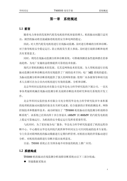
TN8000 机组振动在线监测 分析故障诊断系统
SL
SL
SL
SL
SL
CH1 CH1 CH1
CH1 CH1
KP
CH2 CH2 CH2 CH2 CH2
CH3 CH3 CH3 CH3 CH3
与此同时,为了更好地为电厂服务,华北电力科学研究院建设了机组远程诊 断中心。中心拥有由华北电科院汽机所和华科同安公司共同组成的技术专家组, 专门负责对联网机组的振动数据进行定期归档管理、对机组出现的异常振动进行 分析、对机组的故障进行诊断并提出处理意见。
目前,TN8000 系统正在全国各地不同容量的机组上推广应用。
1.8.2 完备的数据存储和数据管理 TN8000 系统自动形成多个数据库。所有数据库均存储在数据采集箱内的硬 盘中。 实时数据:记录当前实时的数据,一秒钟刷新一次。 小时数据库:记录当前最新 1 小时数据,默认间隔 2 秒。 天数据库:记录当前最新 1 天数据,默认间隔 60 秒。 周数据库:记录当前最新 1 周数据,默认间隔 420 秒。 月数据库:记录当前最新 1 月数据,默认间隔 30 分钟。 年数据库:记录当前最新 1 年数据,默认间隔 360 分钟。 升降速数据库:记录各次开停机过程的数据,转速间隔默认为 20rpm,可存 储最新 10 次开停机数据。 变负荷数据库:记录各次变负荷过程的数据,负荷间隔默认为 10MW。 盘车数据库:存储机组盘车时的有关数据。 黑匣子数据库:黑匣子数据用来记录事故发生前后机组振动变化的详细信 息。TN8000 系统可以记录最新十次的事故数据,每次可记录事件前 15 分钟和事 件后 15 分钟的数据。当外接跳机信号硬触发或当机组振动超过 TN8000 设定的 危险值时触发黑匣子功能,将事故发生前后的数据快速记录到黑匣子数据库中,
智能环保数采仪快速安装指南V2.2-20140527

功能说明
电源正极 保护地 电源地 无线数传单元电源正 无线数传单元电源负 清除发送 请求发送 接收数据 发送数据
地
串口 2
串口 3
串口 4 串口 5 串口 6 串口 7 串口 8 串口 9 调试终端 CONSOLE
三线制 RS232
三线制 RS232 三线制 RS232 三线制 RS232 三线制 RS232 三线制 RS232 RS485
表 1-3 主控单元指示灯说明
1、主控单元前面板接口
图 1-4 主控单元接口示意
主控单元前面板接口(从右到左说明)如表:
接口
类型
主控单元电源 端子
DTU 电源
端子
串口 1 (DTU 串口)
五线制 RS232
端子名称
+12V PGND GND DTU+ DTUCT1 RT1 RX1 TX1 GND
9 / 36
1、开箱检查外观及其配件是否完整。 2、上电运行检查软件功能是否正常。 3、如果发现外观及配件异常请您电话或者邮件通知我司售后工作人 员,说明异常情况,我司会尽快给您答复。 4、如果发现软件功能异常,请您将现象(打印消息截图、照片等)记 录清楚并与我司确认问题。 我司确认问题后会第一时间给您解决方案,并指导您解决问题,尽量 避免将设备直接返回而影响您的正常使用。 再次感谢您的配合与支持,祝您身体健康、工作愉快!
3 / 36
引言
名词解释 国标:《HJ/T212-2005 污染源在线自动监控(监测)系统数据传输标准》,
下文简称“国标” 主控单元:箱体内集数据分析、存储、上报等功能的设备 无线数传单元:专门用于将串口数据转换为 IP 数据或将 IP 数据转换为串口 数据通过无线通信网络进行传送的无线终端设备,简称 DTU 监测因子: 接入主控单元的污染物名称,如 COD、氨氮等
采集器安装调试

采集器换装与调试一、换装1.现场换装首先查看采集的通信参数和表号。
进入采集器主页,按上下键把光标选到通讯参数,按确定键,选中查看通讯参数,按确定键,把采集地址和通信区位码抄下来,再按返回键回到主页,把光标移到抄表设置,按确定键,选中查看抄表设置,按确定键,进来后按指下键查看电表,按顺序把表号记下来。
然后查清电源,有保险的断开保险,无保险的要做好绝缘,防止接地。
遇到采集器电源是两路进线的,找个稳定电源,剩下那路做好绝缘。
2.采集器现场需要接电源、485信号线、安装SIM卡和信号天线。
2.1.采集器电源接点在最下层,分为Ua、Ub、Uc、Un,统一接Ub、Un,就是第5和第10接线点.采集器电压允许范围在100v-220v±20%。
2.2.485信号线接点在电源的上层,统一接A1、B1,就是第33和34接线点.485信号线是用来抄电表数据.2.3.SIM卡应安装通讯模块里,天线装在模块下侧天线插座上.二、调试1.东方维斯顿采集通电以后电源灯常亮.RS485-1\RS485-2抄表时红灯绿灯交替闪烁.模块电源指示灯常亮,NET指示灯与主站联系,常亮后与主站建立了连接。
T/R指示灯处于发送接收状态。
红绿交替闪烁。
2.给主站打电话,把现场新换的采集器条码号和表号报给主站。
报完后把终端地址和区位码输入到新的采集器里。
进入采集器主页,按上下键把光标移到第3项通讯参数,按确定键,进去选中修改信道参数,进去后把光标选到终端地址,按确认,光标显示不明显了,用上下左右键来设置地址。
(如果设置错误,返回键就是删除键)设置完成按确定键,光标又恢复原始样子,按上下键可以移动光标。
把光标移到区位码,按确定键,再把区位码设置上,设置完成按确定键。
把光标再移到GPRS 选择,按确认键。
进去后一直按下键,看见保存两个字,把光标移到保存上,按确认键,显示保存成功,就可以按返回键退出。
在进第3项通信参数,选查看信道参数,检查一下数据是否正确,不正确再进去重新设置,再保存。
TN8000说明书第二章
22
华科同安
TN8000 使用手册
系统软件安装
其它参数可在 TN8000 程序中“系统配置”对话框中根据现场情况进行设置。 详见第三章系统配置。
2.1.5.3 主监视图显示设置 根据现场实际机组的测点布置情况,用 WINDOWS 提供的画笔修改“主监视图
n.BMP”。
根据主监视图上需要显示的通道数修改“主监视图 n.INI”配置文件。其中
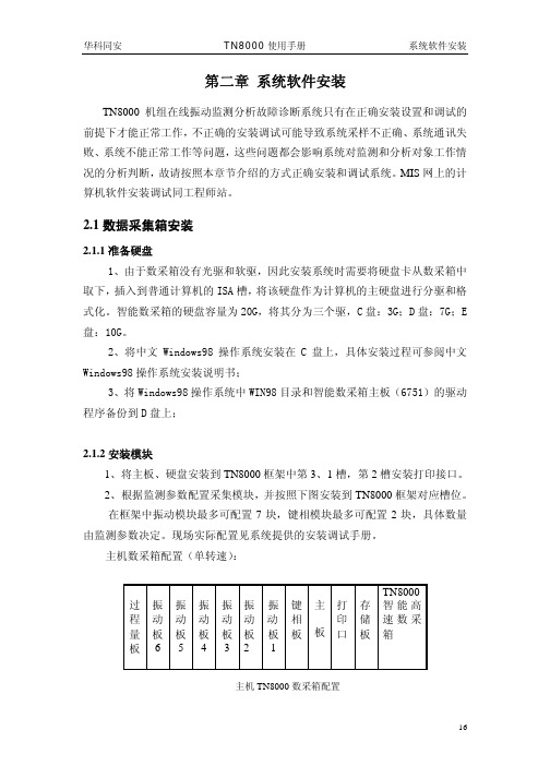
3、将 Windows98 操作系统中 WIN98 目录和智能数采箱主板(6751)的驱动 程序备份到 D 盘上;
2.1.2 安装模块 1、将主板、硬盘安装到 TN8000 框架中第 3、1 槽,第 2 槽安装打印接口。 2、根据监测参数配置采集模块,并按照下图安装到 TN8000 框架对应槽位。 在框架中振动模块最多可配置 7 块,键相模块最多可配置 2 块,具体数量
[通道数] 振动=24 缓变量=0 开关量=0 通讯量=61
轴心轨迹=8 功率通道号=9
// 需人工设置 // 机组实际振动通道数 // 实际采集过程量通道数 // 实际采集的开关量通道数 // 通讯过来的过程量通道数 // 上述三者相加为总的模拟量通道数 // 机组通道对数 // 功率通道在过程量中的通道序号(从 1 开始)
0 显示 1 不显示
小数点=
0 整数 1 一位 2 二位
2 新建坐标
[设置] 设置=0
[显示] //最多可显示前 48 个通道,振动通道在前,过程量在后 显示 1=0 显示 2=0 显示 3=0
… 显示 47=1 显示 48=1
[小数点] 小数点 1=0
23
华科同安
TN8000 使用手册
小数点 2=0 小数点 3=1 … 小数点 47=2 小数点 48=2
- 1、下载文档前请自行甄别文档内容的完整性,平台不提供额外的编辑、内容补充、找答案等附加服务。
- 2、"仅部分预览"的文档,不可在线预览部分如存在完整性等问题,可反馈申请退款(可完整预览的文档不适用该条件!)。
- 3、如文档侵犯您的权益,请联系客服反馈,我们会尽快为您处理(人工客服工作时间:9:00-18:30)。
TN8000数采箱如何安装系统模块(HSC-1812)及存储模块(SATA接口)步骤1:数采箱框架的调整及电源线的梳理上图是准备安装主板HSC-1812及其配套硬盘的数采箱,右侧三个槽位的上方金属挡片已卸下,从左侧数第9,第10槽位下方的黑色U型槽需去掉,所有槽位都没有插模块。
如果是现场升级HSC-1812系统模块及其配套存储模块,需将数采箱从机柜中卸下,并将所有模块拔出,达到上图所示状态才能完成以下操作。
将上图所示9处螺丝拧松,但不要拧下来,将总线板按箭头所示方向下挪。
使所有螺丝达到如图所示状态后拧紧。
注:因为HSC-1812系统模块及其配套存储模块的上侧金属挡片略厚,以上步骤主要保证总线板上方留的空隙足够大,方便模块插拔。
再将上图所示8个螺丝卸下。
将塑料壳向右平推。
平推到底后可轻轻拉出壳体。
上图是壳体下方的固定件,它是L型结构,所以我们之前的操作一定要先平移再向外取出壳体,不要暴力拆卸,以免损坏固定件。
接下来查看一下数采箱电源提供的电源接口,是否有给SATA硬盘的供电接口。
因为数采箱电源批次的关系,2012年前的数采箱电源是不带SATA硬盘的供电接口的,下面将针对两种电源的情况分别进行介绍。
先介绍电源自带接口的情况。
将SATA电源接头抽出。
按蓝框所示将前一段的接头剪掉。
剪掉后效果如图。
如图所示将接头从电源控制线(黑绿双绞线,部分电源控制线为4芯或其他颜色)下方穿过。
拿一根扎带按图中位置穿过电源散热孔。
按如图所示扎紧。
扎好后效果如图,注意留好电源线的长度,超出数采箱部分刚好可以手持即可,这样既方便了电源线的插拔,将来也不会因线留的太长,塞满了存储模块与数采箱电源的空隙,造成安装和更换时的麻烦。
下面介绍数采箱电源没有SATA电源接口的情况。
如图所示我们需要添加一个电源转接头。
如图所示抽出一根4P电源接头。
图中蓝框为下一步骤要操作的位置。
如图所示位置将带有软驱供电接口的前一段接头剪掉。
剪掉后效果如图。
连接电源转接头。
如图所示将接头从电源控制线(黑绿双绞线,部分电源控制线为4芯或其他颜色)下方穿过。
拿一根扎带按图中位置穿过电源散热孔。
按如图所示扎紧。
扎好后效果如图,注意留好电源线的长度,超出数采箱部分刚好可以手持即可,这样既方便了电源线的插拔,将来也不会因线留的太长,塞满了存储模块与数采箱电源的空隙,造成安装和更换时的麻烦。
按如图所示将塑料壳体安装回数采箱,注意壳体底部的两个L型固定件,应先按箭头方向垂直放入蓝框所示的安装孔,然后再向数采箱中部方向平移。
壳体装回后,将如图所示8个螺丝装回拧紧。
最终效果如图所示,框架的调整及电源线的布置即完成。
步骤2:系统模块(HSC-1812)及存储模块(SATA接口)的安装先来认识一下系统模块(HSC-1812)上的各个接口系统模块全图。
板载2个SATA接口,我们使用SATA1接口。
板载3个USB接口,我们使用USB1。
板载4个串口,我们使用COM1和COM2。
硬盘指示灯接口,红线插正端。
电池旁边的2p排针可使COMS放电,需恢复出厂设置时用工具短接一下即可。
内存插槽,厂供1G内存。
下面正式开始介绍装配过程,请注意装配顺序为:USB接口---系统模块---存储模块。
先安装USB接口,将螺丝拧紧,如图所示绕一圈后用扎带扎紧,黑色接头轻轻扭向左侧,红线向下。
在主板对应位置插入串口转接线,如图所示,注意红线的朝向。
在主板对应位置插入硬盘指示灯连接线,注意红线的朝向。
将已固定在机箱中的USB接口如图所示连接到主板对应接口上,注意红线的朝向。
将系统模块插入对应槽位,用螺丝拧紧。
如图所示连接好存储模块的SATA数据线。
如图所示接好电源线。
将存储模块插入数采箱,将串口转接线轻挪向外侧,将红色的SATA数据线理顺后压向数采箱内侧。
如图所示将SATA数据线接头插好。
如图所示插好串口转接线和硬盘指示灯线。
连接完成后效果如图,要求各连接线前后层次分明,没有交叉和缠绕,便于插拔和维护。
BIOS设置指南(Y9038004)下面介绍如何设置系统模块(HSC-1812)的BIOS,因为研祥(Evoc)不同批次的BIOS 版本略有不同,本指南适用于BIOS版本为Y9038004的系统模块。
查看版本号的方法:开机后出现BIOS自检画面时按下“暂停Pause”键,自检画面将暂停,黄线标示位置即为版本号,再按任意键自检继续进行,开始进入系统。
如果要进入BIOS设置界面请在开机自检开始后按“删除Del”键。
进入BIOS后,在屏幕右侧框内是操作说明和选中项的功能介绍,按提示可对各个项进行设置。
首先我们选中“Exit”界面下的“Load Optimal Defaults”项,按“回车Enter”键。
出现如图所示提示界面,选“OK”项,按“回车Enter”键确认。
注:该项功能是“载入故障安全缺省值”。
使用此菜单载入工厂默认值作为稳定的系统使用。
它是一个我们常会用到的项,在数采箱出现故障时,如怀疑是主板的问题,我们可以先选择载入该项恢复默认值,看是否故障消除。
如果没有效果,我们可以尝试将COMS 电池放电,方法是短接一下上图蓝框所示排针,然后再进BIOS设置其他选项,看是否可消除故障,但在没有问题的情况下,请不要进行以上操作。
另,当我们发现系统时间在数采箱重启后总是恢复到一个固定的时间点,即使在Windows 系统下设置正确时间,只要重启系统,时间就会恢复到该固定时间,说明CMOS电池没电了,请将上图所示纽扣电池更换就可以消除该问题。
如开机后主板不自检,且发出“滴滴滴”连续三声报警提示音,说明内存自检未通过。
首先,将内存拔下,清理内存槽后,重新插入,如故障依旧则需要更换新的内存。
选中“Advanced”界面下的“SuperIO Configuration”项,按“回车Enter”键进入。
将如图所示“OnBoard Floppy Controller”项设置为“Disabled”。
该项功能是关闭软驱控制器,从而提高开机速度,同时在Windows系统中也将不显示软驱驱动器。
选中“Chipset”界面下的“Flat Panel Type”项,按“回车Enter”键调出分辨率列表,选择“1024X768”。
注:如果进入Windows系统后发现分辨率不能设置成1024X768,请检查BIOS中这一项是否正确设置。
所有设置完成,保存退出。
BIOS设置指南(I9038002)下面介绍如何设置BIOS版本为I9038002的系统模块(HSC-1812)。
查看版本号的方法:开机后出现BIOS自检画面时按下“暂停Pause”键,自检画面将暂停,黄线标示位置即为版本号,再按任意键自检继续进行,开始进入系统。
如果要进入BIOS设置界面请在开机自检开始后按“删除Del”键。
进入BIOS后,在屏幕右侧框内是操作说明和选中项的功能介绍,按提示可对各个项进行设置。
首先我们选中“Exit”界面下的“Load Optimal Defaults”项,按“回车Enter”键。
出现如图所示提示界面,选“OK”项,按“回车Enter”键确认。
选中“Advanced”界面下的“SuperIO Configuration”项,按“回车Enter”键进入。
将如图所示“OnBoard Floppy Controller”项设置为“Disabled”。
该项功能是关闭软驱控制器,从而提高开机速度,同时在Windows系统中也将不显示软驱驱动器。
选中“Advanced”界面下的“ISA I/O Decode Configuration”项,按“回车Enter”键进入。
将“Decode I/O Base0”设置为“0100”(数字键输入),将“Decode I/O Sise0”设置为“256Bytes”。
这里设置的是双列直插型采集模块的采集地址,如设置错误,采集板将无法工作。
将“Decode I/O Base6”设置为“0500”(数字键输入),将“Decode I/O Sise6”设置为“256Bytes”。
这里设置的是贴片型采集模块的采集地址,如设置错误,贴片型采集板将无法工作(数采箱框架中没有贴片型采集模块,该项可不设)。
选中“Chipset”界面下的“Flat Panel Type”项,按“回车Enter”键调出分辨率列表,选择“1024X768”。
所有设置完成,保存退出。
一键还原的使用数采箱的存储模块中装有微软Windows系统,在使用过程中我们经常会碰到一些系统问题,如中毒,系统文件损坏等,造成无法正常进入系统,这时我们可以使用出厂时预装的一键还原功能,将C盘恢复到出厂时的状态。
步骤如下:重启数采箱,当屏幕上出现“******Press[F11]to Start recovery syetem******”提示时,按下“F11”键,开始一键还原。
还原过程全自动完成,还原完成后将自动重启数采箱。
提示界面系统镜像还原界面。
还原完成,重启提示界面。
注:一键还原功能保护系统的原理在于,在硬盘上设置一个隐藏分区,该分区可自启动,并调用Ghost软件将C盘镜像存放在该分区中,当C盘故障时不会影响到隐藏分区,并可用保留的原始镜像还原系统。
但如果硬盘本身出现硬件故障,如坏道,分区表错误等,一键还原也将无法使用,此时开机将不会出现“******Press[F11]to Start recovery syetem******”的提示,这种情况只能更换新的硬盘。