ROSEMOUNT 3051变送器HART375树形菜单中英文对照
375 3051用户使用培训教材

艾默生过程控制公司测量仪表部(RMT)
2008.2
3051C/T的基本性能指标
额定参考精度:0.065%URV( 出厂标定量程)。 总体TPE:+/-0.15%出厂标定量程(+/-28C;1000PS;1:5量程) 额定稳定性:0.125%URL/5年。 6种隔离膜片的材质,两种灌充液选项。 适合各种安装形式的20种过程法兰及远传选项。 最大安装零点影响:+/-1.25”H2O.(0.3Kpa) 动态响应:T63=100MS.(当今最快的压变) HART-5通讯协议支持77个以上参数的组态输出。 现场总线型可提供1*LCD;2*AI;1*PID以及可选的ISEL;ARTH;SGCR;INT功能模块。 最小差压测量范围:3051CD0/0.1”H2O.
• Alarm levels indicated on label • Standard Alarm:3.75-21.75ma • NAMUR Compliant Alarm Levels 3.6-22.5ma • Board part number on label Power Connection
怎样使用375HC 对3051系列进行组态调校
什么情况需要进行校验? 仪表PV值与实际压力不一致. 仪表PV值与实际压力一致,但4-20MA 输出与标准表不一致.
上述两个参数均对不上.
使用FULL TRIM,此项调整为两点校验,需标准压力源进行打 压。
不同的变送器对曲线的矫正度有不同的限制,通常为满量程 的3-5%!
如PV 仍有误差,可再进行一次.如PV 正确,但4.00MA 有误差 ,则需进行校验菜单的第2项- Trim analog output/校准模拟 量输出.
Rosemount3051压力变送器使用手册(中文)

使用手册00809-0100-4001,版本 EA 采用HART协议的3051型压力变送器3051 型使用手册00809-0100-4001,版本 EA 3051 型3051 型压力变送器注意在使用产品前务必阅读本手册。
为了确保人身安全和系统安全并使产品达到最佳性能,在产品安装、使用或维修前必须确保已完全理解本手册中的内容。
如此中文版本使用手册个别内容与英文版本描述不同,请以英文版本为准。
免费客户服务热线:800-820-1996 联系当地的罗斯蒙特销售办事处,请拨打:北京 010-********上海 021-********广州 020-********西安 029-********乌鲁木齐 0991-*******警告本手册描述产品的设计用途不包括核级资质应用领域。
将非核级资质产品用于需要核级资质硬件或产品的应用领域会产生错误的读数。
如需罗斯蒙特核级资质产品,请联系当地罗斯蒙特销售代表。
罗斯蒙特 3051 型智能压力变送器受下列一种或多种专利保护:美国专利证书号:4466290;4612812; 4791352; 4798089; 4818994; 4866435;4878012;4988990; 4926340; 5083091; 5122794; 5166678; 5248167;5278543; 5287746; 5329818;5333504; 5585777; 6017143; 6119047;6295875; Des. 317266; Des. 318432; Des 342456。
具体情况取决于相关型号。
其他颁发的及等待颁发的美国和外国专利。
艾默生过程控制有限公司履行所有法律义务以满足欧盟产品要求。
3051 型使用手册00809-0100-4001,版本 EA 3051 型目录第一章简介如何使用手册 . . . . . . . . . . . . . . . . . . . . . . . . . . . . . . . . . . . . . . . .服务支持 . . . . . . . . . . . . . . . . . . . . . . . . . . . . . . . . . . . . . . .包括型号. . . . . . . . . . . . . . . . . . . . . . . . . . . . . . . . . . . . . . . . . . . .变送器概述. . . . . . . . . . . . . . . . . . . . . . . . . . . . . . . . . . . . . . . . . .1-11-11-21-3第二章安装概述 . . . . . . . . . . . . . . . . . . . . . . . . . . . . . . . . . . . . . . . . . . . . . . .安全信息 . . . . . . . . . . . . . . . . . . . . . . . . . . . . . . . . . . . . . . . .. . . .警告 . . . . . . . . . . . . . . . .. . . . . . . . . . . . . . . . . . . . . . . . . .总体描述 . . . . . . . . . . . . . . . . . . . . . . . . . . . . . .. . . . . . . . . . . . .机械描述 . . . . . . . . . . . . .. . . . . . .. . . . .. . . . .. . . . . . . . . . . .量程描述 . . . . . . . . . . . .. . . .. .. . . . . . . . . . . . . . . . .. . . . . .环境描述. . . . . . . . . . . . . . . . . . . . . . . . . . . . . . . . .. . . . . . . . . .安装程序. . . . . . .. . . .. . .. . . . . . . . . . . . . . . . . . . . . . . . . . . . . . . .安装变送器. . . . . . . . . . . . ... . . . . . . . . . . . . . . . . . . . . . . . .过程连接. . . . . . . . . . . . . . . . . . . . . .. . . . . . . . . . . . . . . . . .外壳旋转描述. . . . . . . . . . . . . . . . . . . . . .. . . . . . . . . . . . . . . .设置跳线 . . . . . . . . . . . . . . . . . . . . . . . . . . . . . . . . . . . . . . . .接线并接通电源. . . . . . .. . . . . . . . . . . . .. . . . . . . . . . . . . . .危险场所. . . . . . . . . . . . . . . . . . . . . . . . . . . . . . . . . . . . . . . . . . .变送器外壳接地. . . . . . . . . . . . . . . . . . .. . . . . . . . . . . . . . . . .安装液晶显示器 . . . . . . . . . . . . . . . . . . . . . .. . . . . . . . . . . . . . .305 型和 306 型一体化阀组. . . . . . . . . . . .. . ... . . . . . . . . . . . . .安装程序. . . . . . . . . . .. . . . . . . . . . . . . . . . . . . . . . . . . . .2-12-12-12-22-32-32-42-62-62-112-132-142-162-182-182-192-222-22第三章组态概述 . . . . . . . . . . . . . . . . . . . . . . . . . . . . . . . . . . . . . . . . . . . . . . .安全信息 . . . . . . . . . . . . . . . . . . . . .. . . . . . . . . . . . . . . . . . . . . .报警 . . . .. . . . . . . . . . . . . . . . . . . . . . . . . . . . . . . . . . . . . . .试验台上用 HART 试运行. . . . . . . . . .. . . . . . . . . . . . . . . . . . . .按照手册设置回路. . . . . . . . . . . . . . . . . . . . . . . . . . . . . . . . . . .接线图. . . . . . . . . . . . . . . . . . . . . . . . . . . . . . . . . . . . . . . . . .275 型 HART 通讯装置. . . . . . . . . . . . . . . . . . . . . . . . . . . . . . . .审核组态数据. . . . . . . . . . . . . . . . . . . .. . . . . . . . . .. . . . . . . . . .检查输出. . . . . . . . . . . . . . . . . . . . . . . . . . . . . . . . . . . . . . . . . .过程变量. . . . . . . . . . . . . . . . . . . . . . . . . . . . . . . . . . . . . . . . .传感器温度. . . . . . . . . . . . . . . . . . . . . . . . . . . . . . . . . . . . . .基本设置 . . . . . . . . . . . . . . . . . . . . . . .. . . . . . . . . . . . . . . . . . . . .设置过程变量单位. . . . . . . . . . . . . . .. . .. . . . . . . . . . . . .设置输出 . . . . . . . . . . . . . .. . . . . . . . . . . . . . . . . . . . . . . . . .重置量程 . . . . . . . . . . . . . . . . . . . . . . . . . .. . . . . . . . . . . . . .阻尼 . . . . . . . . .. . . . . . . . . . . . . . . . . . . . . . . . . . . . . . . . . .3-13-13-13-23-23-33-43-73-73-73-83-83-83-93-103-163051 型液晶显示器. . . . . . . . . . . . . . . . . . . . . . . . . . . . . . . . . . . . . . . . . .标准显示组态. . . . . . . . .. . . . . . . . . . . . . . . . . . . . . . . . . .自定义显示组态. . . . . . . . . . . . . . . .. . . . . . . . . . . . . . . . . . 详细设置 . . . . . . . . . . . . . . . . . . . . . . . . . . . . . . . . . . . . . . . . . .故障模式报警和饱和电平. . . . . . . . . . . . . . . . . . . . . . . . . . .触发模式报警和饱和电平. . . . . . . . . . . . . . . . . . . . . . . . . . . .多站式模式报警和饱和值. . . . . . . . . . . . . . . . . . . . . . . . . . . .报警电平检验. . . . . . . . . . . . . . . . . . . . . . . . . . . . . . . . . . . .传感器温度单位 . . . . . . . . . . . . . .. . . . . . . . . . . . . . . . . . . . . 诊断和服务. . . . . . . . . . . . . . . . . . . . . . . . . . . . . . . . . . . . . .变送器测试 . . . . . . . . . . . . . . . . . . . . . . . . . . . . . . . . . . . . . .回路测试 . . . . . . . . . . . . . . . . . . . . . . . . . . . . . . . . . . . . . . . . 先进功能 . . . . . . . . . . . . . . . . . . . . . . . . . . . . . . . . . . . . . . . . .保存、取消和克隆组态数据 . . . . . . . . . . . . . . . . . .. . . . .触发模式 . . . . . . . . . . . .. . . . . . . . . . . . . . . . . . . . . . . . . . . . 多站式通讯 . . . . . . . . . . . . . . . . . . .. . . . . . . . . . . . . . . . . . . . . .改变变送器地址 . . . . . . . . . . . . . . . . . . . . . . . . . . . . . . . . . .与多站式变送器通讯 . . . . . . . . . . . . . . . . . . . . . .. . . . . . . . .对多站式变送器查询. . . . . . . . . . . . . . . . . . . . . 3-16 3-17 3-17 3-19 3-19 3-20 3-20 3-20 3-20 3-21 3-21 3-21 3-22 3-22 3-24 3-25 3-26 3-27 3-27第四章使用和维护概述 . . . . . . . . . . . . . . . . . . . . . . . . . . . . . . . . . . . . . . . . . . . .安全信息 . . . . . . . . . . . . . . . . . . . . . . . . . . . . . . . . . . . . . . . . .警告 . . . . . . . . . . . . . . . . . . . . . . . . . . . . . . . . . . . . . . . . . . .标定 . . . . . . . . . . . . . . . . . . . . . . . . . . . . . . . . . . . . . . . . . . . . . .标定概述 . . . . . . . . . . . . . . . . . . . . . . . . . . . . . . . . . . .确定标定频率 . . . . . . . . . . . . . . . . . . . . . . . .选择微调程序 . . . . . . . . . . . . . . . . . . . . . . . . . . . . . .传感器微调 . . . . . . . . . . . . . . . . . . . . . . . . . . . . . . . . . . . . . .零点微调 . . . . . . . . . . . . . . . . . . . . . . . . . . . . . . . . . . . . . .全量程微调 . . . . . . . . . . . . . . . . . . . . . . . . . . . . . . . . . . . . .恢复工厂微调 . . . . . . . . . . . . . . . . . . . . . . . . . . . . . . . . . . . .模拟输出微调 . . . . . . . . . . . . . . . . . . . . . . . . . . . . . . . . . . .数/模转换微调. . . . . . . . . . . . . . . . . . . . . . . . . . . . . . . . . .应用其他刻度进行数/模转换微调. . . . . . . . . . . . . . . . . .静压补偿 . . . . . . . . . . . . . . . . . . . . . . . . . . . . . . . . . . . . . .诊断信息 . . . . . . . . . . . . . . . . . . . . . . . . . . . . . . . . .本机零点及量程(本机键)软件锁定 . . . . . . . . . . . . . . . .本机零点及量程的实体拆除(本机键) . . . . . . . . . . . . .选择低功耗输出量程 . . . . . . . . . . . . . . . . . . . . . .详细设置 . . . . . . . . . . . . . . . . . . . . . . . . . . . . . . . . . . . . . . . . . .本机量程与零点控制(本机键). . . . . . . . . . . . . . . . . .4-14-14-14-24-34-44-64-64-74-84-94-104-104-114-124-144-194-194-204-204-20第五章故障检修概述 . . . . . . . . . . . . . . . . . . . . . . . . . . . . . . . . . . . . . . . . . . . . . . .安全信息 . . . . . . . . . . . . . . . . . . . . . . . . . . . . . . . . . . . . . . . . .警告 . . . . . . . . . . . . . . . . . . . . . . . . . . . . . . . . . . . . . . . . . . . .拆卸变送器之前. . . . . . . . . . . . . . . . . . . . . . . . .拆卸程序 . . . . . . . . . . . . . . . . . . . . . . . . . . . . . . . . . . .从服务地点拆除变送器 . . . . . . . . . . . . . . . . . . . . . .拆除端子块 . . . . . . . . . . . . . . . . . . . . . . . . . . . . . .拆除电子线路板 . . . . . . . . . . . . . . . . . . . . . . . . . . . .从电子元件外壳中拆除传感器模块 . . . . . .5-15-15-15-35-35-35-45-45-5目录-2使用手册00809-0100-4001,版本 EA 3051 型重新装配程序 . . . . . . . . . . . . . . . . . . . . . . . . . . . . . . . . . . .安装电子线路板 . . . . . . . . . . . . . . . . . . . . . . . . . . . . .安装端子块 . . . . . . . . . . . . . . . . . . . . . . . . . . . . . . . .重新装配过程传感器本体 . . . . . . . . . . . . . . . . . . . . . 5-5 5-6 5-6 5-7附录 A 参考信息性能说明 . . . . . . . . . . . . . . . . . . . . . . . . . . . . . . . . .详细性能说明. . . . . . . . . . . . . . . . . . . . . . . . . .参考精度 . . . . . . . . . . . . . . . . . . . . . . . . . . . . . . . . . . . .环境温度. . . . . . . . . . . . . . . . . . . . . . . . . . . . . . . . . . .静压影响 . . . . . . . . . . . . . . . . . . . . . . . . . . . . . . . . . . .动态性能 . . . . . . . . . . . . . . . . . . . . . . . . . . . . . . . . . .安装位置影响 . . . . . . . . . . . . . . . . . . . . . . . . . . . . . . . .振动影响 . . . . . . . . . . . . . . . . . . . . . . . . . . . . . . . . . . . . . . . .电源影响 . . . . . . . . . . . . . . . . . . . . . . . . . . . . . . . . . . . .射频干扰影响 . . . . . . . . . . . . . . . . . . . . . . . . . . . . . . . . . . . . . . . . . . .耐瞬变电压保护 . . . . . . . . . . . . . . . . . . . . . . . . . . . . . . . . . . . .功能说明 . . . . . . . . . . . . . . . . . . . . . . . . . . . . . . . . . . .量程及传感器极限值 . . . . . . . . . . . . . . . . . . . . . . . . . . . . . . . .形体说明 . . . . . . . . . . . . . . . . . . . . . . . . . . . . . . . . . . .尺寸图 . . . . . . . . . . . . . . . . . . . . . . . . . . . . . . . . . . . .订购信息 . . . . . . . . . . . . . . . . . . . . . . . . . . . . . . . . . . . . .零件清单. . . . . . . . . . . . . . . . . . .. . . . . . . . . . . . . . . . . . . . . . .选项 . . . . . . . . . . . . . . . . . . . . . . . . . . . . . . . . . . . . . . . . . . . . . . .HART 协议组态数据表 . . . . . . . . . . . . . . . . . . . . .A-1A-2A-2A-3A-4A-4A-5A-5A-5A-5A-5A-6A-6A-11A-13A-21A-35A-45A-50附录 B 产品认证概述 . . . . . . . . . . . . . . . . . . . . . . . . . . . . . . . . . . . . . . . . . . . . . . .安全信息 . . . . . . . . . . . . . . . . . . . . . . . . . . . . . . . . . . . . . . . . .警告 . . . . . . . . . . . . . . . . . . . . . . . . . . . . . . . . . . . . . . . . . . . .通过认证的制造场所 . . . . . . . . . . . . . . . . . . . . . . . . . . .欧盟指令信息 . . . . . . . . . . . . . . . . . . . . . . . . . . . . . .ATEX 指令 . . . . . . . . . . . . . . . . . . . . . . . . . . . . . . . . . . . . . . . .欧盟压力设备指令(PED)(97/23/EC) . . . . .电磁兼容性(EMC) . . . . . . . . . . . . . . . . . . . . . .其他重要指南 . . . . . . . . . . . . . . . . . . . . . . . . . . . . . . .工厂互检普通场所认证 . . . . . . . . . . . . . . .危险场所认证 . . . . . . . . . . . . . . . . . . . . . . . . . .北美认证. . . . . . . . . . . . . . . . . . . . . . . . . . . . .欧盟认证 . . . . . . . . . . . . . . . . . . . . . . . . . . . . . . . . .日本认证 . . . . . . . . . . . . . . . . . . . . . . . . . . . . . . . .澳大利亚认证 . . . . . . . . . . . . . . . . . . . . . . . . . . . . . . . . .认证组合 . . . . . . . . . . . . . . . . . . . . . . . . . . . .认证图纸. . . . . . . . . . . . . . . . . . . . . . . . . . . . . . . . . . . . . . . .工厂互检03031-1019 . . . . . . . . . . . . . . . . . . . . . . . . . . . . . .加拿大标准协会(CSA)03031-1024 . . . . . . . . .澳大利亚标准协会(SAA)03031-1026 . . . . . . . .B-1B-1B-1B-2B-2B-2B-3B-3B-3B-3B-4B-4B-5B-7B-7B-8B-9B-9B-21B-30目录-33051 型使用手册00809-0100-4001,版本 EA 3051 型第一章简介如何使用本手册本手册所含章节提供罗斯蒙特 3051S 型智能压力变送器系列测量装置安装、使用和维护信息。
HART手操器菜单中英文对照

HART手操器(智能型)、压力pres、量程百分比% rnge3、模拟输出Ao1、自检self test2、状况status 1、键盘输入keypad input1、重定量程Re—2、提供压力值apply values、数/模转换调整D/A trim2、调整模拟输出、校准2、刻度的数/模转换调整scaled D/A trim1、零点调整zero trim32、传感器下限调整lower sensor trimsensor trim 3、传感器上限调整upper sensor trim4、传感器调整点sensor trim points、工位号tag 1、键盘输入keypad input2、单位unit、量程值、提供压力值Apply values1、日期date2、描述符descriptor3、信息message4、写保护write protect5、表头类型meter type传送功能x fer fnctn linear阻尼damp过程变量process variables传感器传感器维修senson servin单位unit 压力pres过程变量% rngekeypad input单位unit apply values detailed setup x fer fnctn lineardamp 、压力pres、过程变量2、量程百分比% rnge3、模拟输出Ao1、回路测试loop test、模拟输出2、数/模转换调整D/A trim、模拟输出报警、刻度的数/模转换调整scaled D/A trim查询poll address、HART输出2请求起始码数目num rea preams、突发模式burst mode1、突发模式选择burst option1、日期datereview 、描述符descriptor3、表头类型、信息message5、型号model、自检6、写保护write protecttest 7、版本号revisior1、测量类型means type gage、传感器信息、隔离膜片材料Isoltor matl3、充液类型fill fluid4、法兰类型flange type5、法兰材料flange matl6、O—型环材料o-ring matl7、排气/排液阀材料drain vent matl8、远传数量final asmbly number9、远传类型devid。
怎样使用HART375对3051系列压力变送器进行组态

怎样使用HART 375对3051系列压力变送器进行组态1 问题提出罗斯蒙特3051系列压力变送器采用HART协议进行通讯,该协议使用了工业标准Bell202频移调制(FSK)技术。
在模拟输出上叠加高频信号可以进行远程通讯.罗斯蒙特采用该技术,能在不影响回路完整性的的情况下,实现同时通讯和输出.如何使用HART协议对3051型压力变送器进行组态,能保证测量仪表设备稳定准确运行。
2 组态3051C 或其它压力变送器与HART 375 手操器的接线如图1所示,现场可接在表的电源端子处,控制室可接在信号端子处。
回路电阻应保证在250~1000Ω 的范围内.图1 HART 375手操器与变送器的连接2.1 进入在线画面打开电源开关,等待HART 375进入主菜单画面,如图2所示界面,此界面有五个选项栏,分别为:HART 应用、现场总线应用、手操器设置、与PC通讯和写字板。
图2 HART 375主界面使用光标笔双击“HART 应用栏",如果手操器与变送器通讯正常,则画面应转入在线画面,如图3所示界面,这个界面会显示在线变送器的各个实时参数,比如实时的过程变量值、电流输出值、量程上限与下限值,其中最重要的是仪表设置这个选项,他是变送器能够进行组态的关键菜单。
图3 与变送器连接在线画面2。
2 组态过程在变送器与手操器通讯正常的情况下,可以双击“仪表设置"菜单即可进入变送器的组态菜单,仪表组态画面有5 个选项,如图4所示显示界面。
图4 仪表设置菜单选项A)双击“显示过程变量”后,您可以察看与变送器相关的所有测量参数.B)进入诊断画面,您可以对仪表进行各种校验及回路测试,另外仪表的各项报警也可以查看!C)进入“基本设置”可以进行修改位号、工程单位、量程、仪表的阻尼系数与传递涵数,因此,这是最常用的菜单。
可以双击5个选项的任一个进入该菜单,图5是菜单3“基本设置"的子菜单。
图5 基本设置子菜单注意:单击左箭头可以退回上一级菜单,单击“×”图标退回主菜单(此时可以关机).单击“HOME"退回在线菜单。
3051罗斯蒙特变送器手册
CD CG CA
S7 One Diaphragm Seal, All-Welded System (Capillary Connection Type) S8 Two Diaphragm Seals, All-Welded System (Capillary Connection Type) S0 One Diaphragm Seal, All-Welded System (Direct Mount Connection Type) S9 Two Diaphragm Seals, All-Welded System (One Direct Mount and One Capillary Connection Type)
•
•
•
•
•
—
25
Rosemount 3051
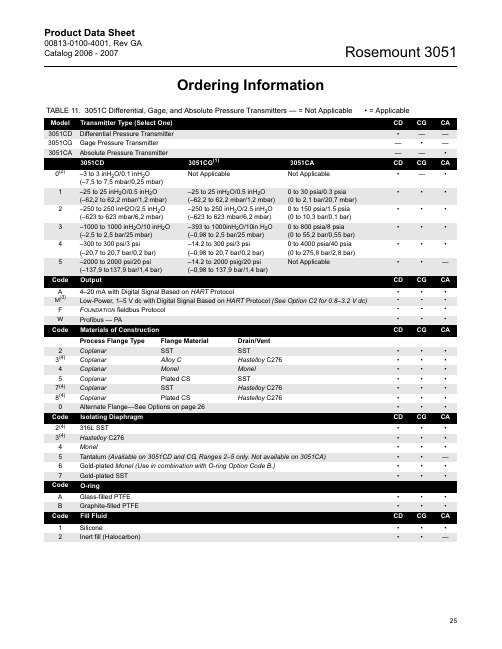
Product Data Sheet
00813-0100-4001, Rev GA Catalog 2006 - 2007
TABLE 11. 3051C Differential, Gage, and Absolute Pressure Transmitters — = Not Applicable • = Applicable
–1000 to 1000 inH2O/10 inH2O (–2,5 to 2,5 bar/25 mbar)
–300 to 300 psi/3 psi (–20,7 to 20,7 bar/0,2 bar)
–2000 to 2000 psi/20 psi (–137,9 to137,9 bar/1,4 bar)
CD CG CA
S1 One Diaphragm Seal (Direct Mount or Capillary Connection Type) S2 Two Diaphragm Seals (Direct Mount or Capillary Connection Type)
Rosemount3051压力变送器使用手册(中文)
使用手册00809-0100-4001,版本 EA 采用HART协议的3051型压力变送器3051 型使用手册00809-0100-4001,版本 EA 3051 型3051 型压力变送器注意在使用产品前务必阅读本手册。
为了确保人身安全和系统安全并使产品达到最佳性能,在产品安装、使用或维修前必须确保已完全理解本手册中的内容。
如此中文版本使用手册个别内容与英文版本描述不同,请以英文版本为准。
免费客户服务热线:800-820-1996 联系当地的罗斯蒙特销售办事处,请拨打:北京 010-********上海 021-********广州 020-********西安 029-********乌鲁木齐 0991-*******警告本手册描述产品的设计用途不包括核级资质应用领域。
将非核级资质产品用于需要核级资质硬件或产品的应用领域会产生错误的读数。
如需罗斯蒙特核级资质产品,请联系当地罗斯蒙特销售代表。
罗斯蒙特 3051 型智能压力变送器受下列一种或多种专利保护:美国专利证书号:4466290;4612812; 4791352; 4798089; 4818994; 4866435;4878012;4988990; 4926340; 5083091; 5122794; 5166678; 5248167;5278543; 5287746; 5329818;5333504; 5585777; 6017143; 6119047;6295875; Des. 317266; Des. 318432; Des 342456。
具体情况取决于相关型号。
其他颁发的及等待颁发的美国和外国专利。
艾默生过程控制有限公司履行所有法律义务以满足欧盟产品要求。
3051 型使用手册00809-0100-4001,版本 EA 3051 型目录第一章简介如何使用手册 . . . . . . . . . . . . . . . . . . . . . . . . . . . . . . . . . . . . . . . .服务支持 . . . . . . . . . . . . . . . . . . . . . . . . . . . . . . . . . . . . . . .包括型号. . . . . . . . . . . . . . . . . . . . . . . . . . . . . . . . . . . . . . . . . . . .变送器概述. . . . . . . . . . . . . . . . . . . . . . . . . . . . . . . . . . . . . . . . . .1-11-11-21-3第二章安装概述 . . . . . . . . . . . . . . . . . . . . . . . . . . . . . . . . . . . . . . . . . . . . . . .安全信息 . . . . . . . . . . . . . . . . . . . . . . . . . . . . . . . . . . . . . . . .. . . .警告 . . . . . . . . . . . . . . . .. . . . . . . . . . . . . . . . . . . . . . . . . .总体描述 . . . . . . . . . . . . . . . . . . . . . . . . . . . . . .. . . . . . . . . . . . .机械描述 . . . . . . . . . . . . .. . . . . . .. . . . .. . . . .. . . . . . . . . . . .量程描述 . . . . . . . . . . . .. . . .. .. . . . . . . . . . . . . . . . .. . . . . .环境描述. . . . . . . . . . . . . . . . . . . . . . . . . . . . . . . . .. . . . . . . . . .安装程序. . . . . . .. . . .. . .. . . . . . . . . . . . . . . . . . . . . . . . . . . . . . . .安装变送器. . . . . . . . . . . . ... . . . . . . . . . . . . . . . . . . . . . . . .过程连接. . . . . . . . . . . . . . . . . . . . . .. . . . . . . . . . . . . . . . . .外壳旋转描述. . . . . . . . . . . . . . . . . . . . . .. . . . . . . . . . . . . . . .设置跳线 . . . . . . . . . . . . . . . . . . . . . . . . . . . . . . . . . . . . . . . .接线并接通电源. . . . . . .. . . . . . . . . . . . .. . . . . . . . . . . . . . .危险场所. . . . . . . . . . . . . . . . . . . . . . . . . . . . . . . . . . . . . . . . . . .变送器外壳接地. . . . . . . . . . . . . . . . . . .. . . . . . . . . . . . . . . . .安装液晶显示器 . . . . . . . . . . . . . . . . . . . . . .. . . . . . . . . . . . . . .305 型和 306 型一体化阀组. . . . . . . . . . . .. . ... . . . . . . . . . . . . .安装程序. . . . . . . . . . .. . . . . . . . . . . . . . . . . . . . . . . . . . .2-12-12-12-22-32-32-42-62-62-112-132-142-162-182-182-192-222-22第三章组态概述 . . . . . . . . . . . . . . . . . . . . . . . . . . . . . . . . . . . . . . . . . . . . . . .安全信息 . . . . . . . . . . . . . . . . . . . . .. . . . . . . . . . . . . . . . . . . . . .报警 . . . .. . . . . . . . . . . . . . . . . . . . . . . . . . . . . . . . . . . . . . .试验台上用 HART 试运行. . . . . . . . . .. . . . . . . . . . . . . . . . . . . .按照手册设置回路. . . . . . . . . . . . . . . . . . . . . . . . . . . . . . . . . . .接线图. . . . . . . . . . . . . . . . . . . . . . . . . . . . . . . . . . . . . . . . . .275 型 HART 通讯装置. . . . . . . . . . . . . . . . . . . . . . . . . . . . . . . .审核组态数据. . . . . . . . . . . . . . . . . . . .. . . . . . . . . .. . . . . . . . . .检查输出. . . . . . . . . . . . . . . . . . . . . . . . . . . . . . . . . . . . . . . . . .过程变量. . . . . . . . . . . . . . . . . . . . . . . . . . . . . . . . . . . . . . . . .传感器温度. . . . . . . . . . . . . . . . . . . . . . . . . . . . . . . . . . . . . .基本设置 . . . . . . . . . . . . . . . . . . . . . . .. . . . . . . . . . . . . . . . . . . . .设置过程变量单位. . . . . . . . . . . . . . .. . .. . . . . . . . . . . . .设置输出 . . . . . . . . . . . . . .. . . . . . . . . . . . . . . . . . . . . . . . . .重置量程 . . . . . . . . . . . . . . . . . . . . . . . . . .. . . . . . . . . . . . . .阻尼 . . . . . . . . .. . . . . . . . . . . . . . . . . . . . . . . . . . . . . . . . . .3-13-13-13-23-23-33-43-73-73-73-83-83-83-93-103-163051 型液晶显示器. . . . . . . . . . . . . . . . . . . . . . . . . . . . . . . . . . . . . . . . . .标准显示组态. . . . . . . . .. . . . . . . . . . . . . . . . . . . . . . . . . .自定义显示组态. . . . . . . . . . . . . . . .. . . . . . . . . . . . . . . . . . 详细设置 . . . . . . . . . . . . . . . . . . . . . . . . . . . . . . . . . . . . . . . . . .故障模式报警和饱和电平. . . . . . . . . . . . . . . . . . . . . . . . . . .触发模式报警和饱和电平. . . . . . . . . . . . . . . . . . . . . . . . . . . .多站式模式报警和饱和值. . . . . . . . . . . . . . . . . . . . . . . . . . . .报警电平检验. . . . . . . . . . . . . . . . . . . . . . . . . . . . . . . . . . . .传感器温度单位 . . . . . . . . . . . . . .. . . . . . . . . . . . . . . . . . . . . 诊断和服务. . . . . . . . . . . . . . . . . . . . . . . . . . . . . . . . . . . . . .变送器测试 . . . . . . . . . . . . . . . . . . . . . . . . . . . . . . . . . . . . . .回路测试 . . . . . . . . . . . . . . . . . . . . . . . . . . . . . . . . . . . . . . . . 先进功能 . . . . . . . . . . . . . . . . . . . . . . . . . . . . . . . . . . . . . . . . .保存、取消和克隆组态数据 . . . . . . . . . . . . . . . . . .. . . . .触发模式 . . . . . . . . . . . .. . . . . . . . . . . . . . . . . . . . . . . . . . . . 多站式通讯 . . . . . . . . . . . . . . . . . . .. . . . . . . . . . . . . . . . . . . . . .改变变送器地址 . . . . . . . . . . . . . . . . . . . . . . . . . . . . . . . . . .与多站式变送器通讯 . . . . . . . . . . . . . . . . . . . . . .. . . . . . . . .对多站式变送器查询. . . . . . . . . . . . . . . . . . . . . 3-16 3-17 3-17 3-19 3-19 3-20 3-20 3-20 3-20 3-21 3-21 3-21 3-22 3-22 3-24 3-25 3-26 3-27 3-27第四章使用和维护概述 . . . . . . . . . . . . . . . . . . . . . . . . . . . . . . . . . . . . . . . . . . . .安全信息 . . . . . . . . . . . . . . . . . . . . . . . . . . . . . . . . . . . . . . . . .警告 . . . . . . . . . . . . . . . . . . . . . . . . . . . . . . . . . . . . . . . . . . .标定 . . . . . . . . . . . . . . . . . . . . . . . . . . . . . . . . . . . . . . . . . . . . . .标定概述 . . . . . . . . . . . . . . . . . . . . . . . . . . . . . . . . . . .确定标定频率 . . . . . . . . . . . . . . . . . . . . . . . .选择微调程序 . . . . . . . . . . . . . . . . . . . . . . . . . . . . . .传感器微调 . . . . . . . . . . . . . . . . . . . . . . . . . . . . . . . . . . . . . .零点微调 . . . . . . . . . . . . . . . . . . . . . . . . . . . . . . . . . . . . . .全量程微调 . . . . . . . . . . . . . . . . . . . . . . . . . . . . . . . . . . . . .恢复工厂微调 . . . . . . . . . . . . . . . . . . . . . . . . . . . . . . . . . . . .模拟输出微调 . . . . . . . . . . . . . . . . . . . . . . . . . . . . . . . . . . .数/模转换微调. . . . . . . . . . . . . . . . . . . . . . . . . . . . . . . . . .应用其他刻度进行数/模转换微调. . . . . . . . . . . . . . . . . .静压补偿 . . . . . . . . . . . . . . . . . . . . . . . . . . . . . . . . . . . . . .诊断信息 . . . . . . . . . . . . . . . . . . . . . . . . . . . . . . . . .本机零点及量程(本机键)软件锁定 . . . . . . . . . . . . . . . .本机零点及量程的实体拆除(本机键) . . . . . . . . . . . . .选择低功耗输出量程 . . . . . . . . . . . . . . . . . . . . . .详细设置 . . . . . . . . . . . . . . . . . . . . . . . . . . . . . . . . . . . . . . . . . .本机量程与零点控制(本机键). . . . . . . . . . . . . . . . . .4-14-14-14-24-34-44-64-64-74-84-94-104-104-114-124-144-194-194-204-204-20第五章故障检修概述 . . . . . . . . . . . . . . . . . . . . . . . . . . . . . . . . . . . . . . . . . . . . . . .安全信息 . . . . . . . . . . . . . . . . . . . . . . . . . . . . . . . . . . . . . . . . .警告 . . . . . . . . . . . . . . . . . . . . . . . . . . . . . . . . . . . . . . . . . . . .拆卸变送器之前. . . . . . . . . . . . . . . . . . . . . . . . .拆卸程序 . . . . . . . . . . . . . . . . . . . . . . . . . . . . . . . . . . .从服务地点拆除变送器 . . . . . . . . . . . . . . . . . . . . . .拆除端子块 . . . . . . . . . . . . . . . . . . . . . . . . . . . . . .拆除电子线路板 . . . . . . . . . . . . . . . . . . . . . . . . . . . .从电子元件外壳中拆除传感器模块 . . . . . .5-15-15-15-35-35-35-45-45-5目录-2使用手册00809-0100-4001,版本 EA 3051 型重新装配程序 . . . . . . . . . . . . . . . . . . . . . . . . . . . . . . . . . . .安装电子线路板 . . . . . . . . . . . . . . . . . . . . . . . . . . . . .安装端子块 . . . . . . . . . . . . . . . . . . . . . . . . . . . . . . . .重新装配过程传感器本体 . . . . . . . . . . . . . . . . . . . . . 5-5 5-6 5-6 5-7附录 A 参考信息性能说明 . . . . . . . . . . . . . . . . . . . . . . . . . . . . . . . . .详细性能说明. . . . . . . . . . . . . . . . . . . . . . . . . .参考精度 . . . . . . . . . . . . . . . . . . . . . . . . . . . . . . . . . . . .环境温度. . . . . . . . . . . . . . . . . . . . . . . . . . . . . . . . . . .静压影响 . . . . . . . . . . . . . . . . . . . . . . . . . . . . . . . . . . .动态性能 . . . . . . . . . . . . . . . . . . . . . . . . . . . . . . . . . .安装位置影响 . . . . . . . . . . . . . . . . . . . . . . . . . . . . . . . .振动影响 . . . . . . . . . . . . . . . . . . . . . . . . . . . . . . . . . . . . . . . .电源影响 . . . . . . . . . . . . . . . . . . . . . . . . . . . . . . . . . . . .射频干扰影响 . . . . . . . . . . . . . . . . . . . . . . . . . . . . . . . . . . . . . . . . . . .耐瞬变电压保护 . . . . . . . . . . . . . . . . . . . . . . . . . . . . . . . . . . . .功能说明 . . . . . . . . . . . . . . . . . . . . . . . . . . . . . . . . . . .量程及传感器极限值 . . . . . . . . . . . . . . . . . . . . . . . . . . . . . . . .形体说明 . . . . . . . . . . . . . . . . . . . . . . . . . . . . . . . . . . .尺寸图 . . . . . . . . . . . . . . . . . . . . . . . . . . . . . . . . . . . .订购信息 . . . . . . . . . . . . . . . . . . . . . . . . . . . . . . . . . . . . .零件清单. . . . . . . . . . . . . . . . . . .. . . . . . . . . . . . . . . . . . . . . . .选项 . . . . . . . . . . . . . . . . . . . . . . . . . . . . . . . . . . . . . . . . . . . . . . .HART 协议组态数据表 . . . . . . . . . . . . . . . . . . . . .A-1A-2A-2A-3A-4A-4A-5A-5A-5A-5A-5A-6A-6A-11A-13A-21A-35A-45A-50附录 B 产品认证概述 . . . . . . . . . . . . . . . . . . . . . . . . . . . . . . . . . . . . . . . . . . . . . . .安全信息 . . . . . . . . . . . . . . . . . . . . . . . . . . . . . . . . . . . . . . . . .警告 . . . . . . . . . . . . . . . . . . . . . . . . . . . . . . . . . . . . . . . . . . . .通过认证的制造场所 . . . . . . . . . . . . . . . . . . . . . . . . . . .欧盟指令信息 . . . . . . . . . . . . . . . . . . . . . . . . . . . . . .ATEX 指令 . . . . . . . . . . . . . . . . . . . . . . . . . . . . . . . . . . . . . . . .欧盟压力设备指令(PED)(97/23/EC) . . . . .电磁兼容性(EMC) . . . . . . . . . . . . . . . . . . . . . .其他重要指南 . . . . . . . . . . . . . . . . . . . . . . . . . . . . . . .工厂互检普通场所认证 . . . . . . . . . . . . . . .危险场所认证 . . . . . . . . . . . . . . . . . . . . . . . . . .北美认证. . . . . . . . . . . . . . . . . . . . . . . . . . . . .欧盟认证 . . . . . . . . . . . . . . . . . . . . . . . . . . . . . . . . .日本认证 . . . . . . . . . . . . . . . . . . . . . . . . . . . . . . . .澳大利亚认证 . . . . . . . . . . . . . . . . . . . . . . . . . . . . . . . . .认证组合 . . . . . . . . . . . . . . . . . . . . . . . . . . . .认证图纸. . . . . . . . . . . . . . . . . . . . . . . . . . . . . . . . . . . . . . . .工厂互检03031-1019 . . . . . . . . . . . . . . . . . . . . . . . . . . . . . .加拿大标准协会(CSA)03031-1024 . . . . . . . . .澳大利亚标准协会(SAA)03031-1026 . . . . . . . .B-1B-1B-1B-2B-2B-2B-3B-3B-3B-3B-4B-4B-5B-7B-7B-8B-9B-9B-21B-30目录-33051 型使用手册00809-0100-4001,版本 EA 3051 型第一章简介如何使用本手册本手册所含章节提供罗斯蒙特 3051S 型智能压力变送器系列测量装置安装、使用和维护信息。
3051变送器HART通信树菜单
1 PROCESS VARIABLES 过程参数
2 ANALOG OUTPUT 模拟输出
3 Analog Output Alarm 模拟输出报警
4 HART OUTPUT HART 输出
1 FIELD DIVICE INFO 信息组装置信息
2 SENSOR INFO 传感器信息
3 METER TYPE 仪表型号
1 Tag
工位号
2 Unit
工程单位
3 RANGE VALUES 测量范围值设置
3 BASIC SETUP 基本设置
4 DEVICE INFO 装置信息
压力 百分度量程 模拟量输出 传感器温度
1 RERANGE 重新设置量程
1 Self test 2 Status
自测试 状态
1 Keypad input 2 Apply Values
零点调校 感器下限调校 传感器上限调校 传感器调校点
1 Keypad inpu 键盘输入 2 Apply Values
提供数值 ( 通过加压 )
1 Date
数据
2 Descriptor 描述信息
3 Message 信息
4 Write Protect 写保护
4 DETAILED SETUP 详细设置
5 REVIEW 检查
5 Transfer Function 输出功能 (线性和开方 )
5 Meter Type 仪表型号
6 Damp
阻尼时间
1 SENSORS 传感器
1 PRESSURE SNSR 压力传感器
2 TEMP. SENSOR 温度传感器
2 SIGNAL CONDITION
信号情况
6 PROCESS VARIABLES
罗斯蒙特HART375说明书
375型现场通讯器
注意 使用375型现场通讯器之前,请阅读操作手册。为保证人身安全和系统安全,以及发挥产品的 最佳性能,使用或维修本产品之前,请深入掌握相应内容。 如果设备需要维修,请与最近的产品代理联系。
© 2004艾默生过程管理。保留所有权利。 艾默生标志为艾默生电气公司的商标和服务标志。 AMS Suite设备管理组合为艾默生电气公司的商标。 罗斯蒙特和SMART FAMILY为罗斯蒙特有限公司的注册商标。 Windows为美国和其他国家微软公司的注册商标。 IrDA为红外数据协会的注册商标。 FOUNDATION为现场总线基金会的商标。 HART为HART通信基金会的注册商标。 Hitachi为Hitachi美国有限公司的注册商标。 所有其他商用标志的所有权归其各自的所有者。 正在申请美国和其他国家的专利号。
使用ScratchPad应用程序 . . . . . . . . . . . . . . . . . . . . . . . . . 8 创建新文档 . . . . . . . . . . . . . . . . . . .. . . . . . . . . . . 9
3
打开已有文档 . . . . . . . . . . . . . . . . . . . . . . . . . . . . 9 输入文本. . . . . . . . . . . . . . . . . . . . . . . . . . . . . . . 9 选择文本. . . . . . . . . . . . . . . . . . . . . . . . . . . . . . . 9 剪切文本 . . . . . . . .. . . . . . . . . . . . . . . . . . . . . . . 9 拷贝文本. . . . . . . . . . . . . . . . . . . . . . . . . . . . . . . 9 粘贴文本 . . . . . . . . . . . .. . . . . . . . . . . . . . . . . . . 9 撤消文本. . . . . . . . . . . . . . . . . . . . . . . . . . . . . . . 9 保存文档 . . . . . . . . . . . . . . . . . .. . . . . . . . . . . . . 9 保存副本 . . . . . . . . . . . . . . . . . . . . . . . . . . . . . . 10 删除文档 . . . . . . . . . . . . . . . . . . . . . . . . . . . . . . 10 退出ScratchPad . . . . . . . . . . . . . . . . . . . . . . . . . . . 10 管理储存. . . . . . . . . . . . . . . . . . . . . . . . . . . . . . . . . . 10 储存类型 . . . . . . . . . . . . . . . . . . . . . . . . . . . . . . . 10 维护. . . . . . . . . . . . . . . . . . . . . . . . . . . . . . . . . . . . 11 电池信息. . .. . . . . . . . . . . . . . . . . . . . . . . . . . . . . 11 检查充电量. . . . . . . . . . . . . . . . . . . . . . . . . . . . . 11 电池充电. . . . . . . . . . . . . . . . . . . . . . . . . . . . . . 11 取出系统卡和电池组. . . . . . . . . . . . . . . . . . . . . . . . . 11 运行自检测. . . . . . . . . . . . . . . . . . . . . . . . . . . . . . . 11 本质安全(IS)区域的操作. . . . . . . . . . .. . . . . . . . . . . . . 11 废物处理. . . . . . . . . .. . . . . . . . . . . . . . . . . . . . . 11
罗斯蒙特3051s差压液位变送器-产品说明书-中文
产品说明书00813-0106-4016, Rev UC2023 年 3 月Rosemount™差压液位变送器和 1199 远传密封件应用■液位、流量、压力、界面、密度■极热和极冷环境■腐蚀、堵塞或粘滞过程■卫生要求■特殊过程连接件成熟、可靠和创新的技术使用资产位号随时获取信息新发运设备包含一个唯一的二维码资产位号,您可以通过它直接从设备访问序列化信息。
通过此功能,您可以:■在您的 MyEmerson 账号上访问设备图纸、图表、技术文档和故障排除信息■优化维修和保持效率的平均时间■确保您定位了正确的设备■省去耗时的先定位和抄录铭牌再查看资产信息的工作罗斯蒙特液位变送器此液位变送器将世界先进的罗斯蒙特压力仪表与直接安装密封件相结合,全部集成为一个型号。
Rosemount 3051SAL、3051L 和 2051L型液位变送器■全焊接系统具备突出的系统可靠性■无线组态提供新数据访问■使用全面的过程连接产品、灌充液、直接安装或毛细管连接件和材料可连接到几乎任何过程■利用 QZ 选件量化和优化整个系统的性能内容成熟、可靠和创新的技术 (2)Rosemount 3051S 电子远程传感器 (ERS™) 系统 (6)Rosemount 3051S Scalable™液位变送器 (26)用于 Rosemount 3051SAL 的法兰密封件 (40)Rosemount 3051L 液位变送器订购信息 (65)Rosemount 2051L 液位变送器 (77)直接安装式密封系统订购信息 (86)远传安装式密封系统订购信息 (92)法兰密封件 (98)螺纹密封件 (123)卫生型密封件 (129)专业密封件 (144)技术规格 (153)产品认证 (173)尺寸图 (216)2023 年 3 月/Rosemount罗斯蒙特 Tuned-System ™ 组件优化结果罗斯蒙特 Tuned-System 组件在高压连接件上采用直接安装密封件,在低压连接件上则采用远程安装(毛细管式)密封件。
罗斯蒙特3051s压力变送器英文说明书
Product Data Sheet00813-0100-4801, Rev BA Catalog 2002 – 2003Model 3051S Series•Best-in-class performance with 0.02% high accuracy •Industry's first 10 year stability under actual process conditions•Unprecedented reliability backed by a limited lifetime warranty•SuperModule ™ design platform enables more cost effective installation and maintenance practices •Scalable functionality to meet your expanding needsContent“Specifications” . . . . . . . . . . . . . . . . . . . . . . . . . . . . . . . . . . . . . . . . . . . . . page Pressure-7“Hazardous Locations Certifications” . . . . . . . . . . . . . . . . . . . . . . . . . . . page Pressure-14“Dimensional Drawings” . . . . . . . . . . . . . . . . . . . . . . . . . . . . . . . . . . . . . page Pressure-16“Ordering Information”. . . . . . . . . . . . . . . . . . . . . . . . . . . . . . . . . . . . . . . page Pressure-24“Model 3051S HART Configuration Data Sheet”. . . . . . . . . . . . . . . . . . . page Pressure-36Model 3051S SeriesProduct Data Sheet00813-0100-4801, Rev BACatalog 2002 – 2003Model 3051S SeriesPressure-4Success goes beyond the transmitter to an enabling platformIntroducing the next evolution in measurement, the Model 3051S Series. This scalable platform enablesimplementation of the best measurement practices from design and installation to maintenance and operations.Best-in-class performance with 0.04% accuracy The Model 3051S delivers cutting edge performance beginning with the SuperModule platform. Among the many advances, Saturn ™ sensing technology incorporates a secondary sensor to optimize performance and expand diagnostic capabilities.Industry's first 10 year stability under actual process conditionsStability begins with an all-welded, 316L SSThermetically sealed SuperModule which houses the single board electronics, thus eliminating moisture and field contaminant effects.Unprecedented reliability backed by a limited lifetime warrantyThe SuperModule design delivers the most reliable platform to further enhance installation practices and advanced diagnostic capabilities.SuperModule design platform enables more cost effective installation and maintenance practices A scalable architecture enables direct mounting of the SuperModule for maximum performance and reliability. The flexible remote mount meter provides access to all digital communications and diagnostics.Scalable functionality to meet your expanding needsFrom basic process variable generation to advanced PlantWeb ™ functionality and highly integrated measurement solutions, the Model 3051S Series meets every application requirement.Rosemount ® Pressure SolutionsModel 3095MV Mass Flow TransmitterAccurately measures differential pressure, static pressure and process temperature to dynamically calculate fully compensated mass flow. See product data sheet 00813-0100-4716.Model 305 and 306 Integral Manifolds Factory-assembled, calibrated and seal-tested manifolds reduce on-site installation costs. See product data sheet 00813-0100-4733.Model 1199 Diaphragm SealsProvides reliable, remote measurements of process pressure and protects the transmitter from hot,corrosive, or viscous fluids. See product data sheet 00813-0100-4016.Model 1195 Integral Orifice andProPlate/Mass ProPlate FlowmetersConvenient ready-to-install assembly designed for small-bore flow measurement of any clean gas, liquid, or vapor. See product data sheet 00813-0100-4686.Annubar Flowmeter SeriesA series of highly accurate and repeatableinsertion-type flowmeters available in 2-in. to 72-in. (50.8 to 1829 mm) line sizes. See product data sheet 00813-0100-4809.Model 405P Compact OrificeA wafer style primary element with an integral three-valve manifold. See product data sheet00813-0100-4810.Product Data Sheet00813-0100-4801, Rev BA Catalog 2002 – 2003Pressure-5Model 3051S SeriesModel 3051S Selection GuideSELECT AN INSTRUMENT CONFIGURATIONModel 3051S_C Coplanar ™ Differential, Gage, and AbsoluteSee ordering information on page Pressure-24.•Performance up to 0.04% accuracy with 200:1 turndown •Available 10 year stability and limited lifetime warranty •Coplanar platform enables integrated manifold, primary element and diaphragm seal solutions •Calibrated spans from 0.1 inH 2O to 4000 psi (0,25 mbar to 276 bar)•316L SST, Hastelloy ® C, Monel ®, Tantalum, gold-plated Monel, or gold-plated 316L SST process isolatorsModel 3051S_T In-Line Gage and AbsoluteSee ordering information on page Pressure-28.•Performance up to 0.04% accuracy with 200:1 turndown•Available 10 year stability and limited lifetime warranty•Calibrated spans from 0.15 to 10000 psi (10,3 mbar to 689 bar)•Multiple process connections available •316L SST and Hastelloy C process isolatorsModel 3051S_L Liquid LevelSee ordering information on page Pressure-30.•Performance up to 0.065% accuracy with 100:1 turndown•Flush, 2-, 4-, and 6-in. extended diaphragms •Multiple fill fluids available•316L SST, Hastelloy, or Tantalum wetted materialsC O P L A N A R /3151_E 27BProduct Data Sheet00813-0100-4801, Rev BACatalog 2002 – 2003Model 3051S SeriesPressure-6CONSIDER PERFORMANCE REQUIREMENTS DETERMINE HOUSING AND PROCESS CONNECTIONUltraClassic•0.04% accuracy, 200:1 turndown•10 year stability and limited lifetime warranty•0.065% accuracy, 100:1 turndown •5 year stability••Product Data Sheet00813-0100-4801, Rev BA Catalog 2002 – 2003Pressure-7Model 3051S SeriesSpecificationsPERFORMANCE SPECIFICATIONSFor zero-based spans, reference conditions, silicone oil fill, SST materials, Coplanar flange (Model 3051S_C) or 1/2 in.- 18 NPT (Model 3051S_T) process connections, digital trim values set to equal range points.Conformance to specification (±3 Sigma)Technology leadership, advanced manufacturing techniques and statistical process control ensure specification conformance to at least ±3 sigma.Reference AccuracyTotal PerformanceLong Term StabilityUltra (1) (2)Classic (1)(2)Model 3051S_CD, CG±0.04% of span; for spans less than 10:1, accuracy =Range 1: ±0.09% of span;for spans less than 15:1, accuracy =Range 0: ±0.09% of span; for spans less than 2:1,accuracy= ±0.045% of URL±0.065% of span; for spans less than 10:1, accuracy =Range 1: ±0.10% of span;for spans less than 15:1, accuracy =Range 0: ±0.10% of span; for spans less than 2:1,accuracy= ±0.05% of URLModel 3051S_T±0.04% of span; for spans less than 10:1, accuracy =±0.065% of span; for spans less than 10:1, accuracy =Model 3051S_CA±0.04% of span; for spans less than 10:1, accuracy =Range 0: ±0.075% of span;for spans less than 5:1, accuracy =±0.065% of span; for spans less than 10:1, accuracy =Range 0: ±0.075% of span;for spans less than 5:1, accuracy =Model 3051S_LNot available±0.065% of span; for spans less than 10:1, accuracy =(1)Stated reference accuracy includes terminal based linearity, hysteresis, and repeatability.(2)For F OUNDATION fieldbus transmitters, use calibrated range in place of span.0.0050.0035+URLSpan ------------% of Span±0.0150.005+URLSpan ------------% of Span±0.0150.005+URLSpan ------------% of Span±0.0250.005+URLSpan ------------% of Span±0.004URLSpan ------------% of Span±0.0065URLSpan ------------% of Span±0.004URL Span ------------% of Span±0.0250.01+URL Span ------------% of Span±0.0065URL Span ------------% of Span±0.0250.01+URL Span ------------% of Span±0.0150.005+URL Span ------------% of Span±Ultra (1)Classic (1)Model 3051S_C CD Ranges 2-3 and CG Ranges 2-5±0.125% of span; for ±50°F (28°C) temperaturechanges, 0-100% relative humidity, up to 1000 psi (68,9 bar) line pressure (CD only), from 1:1 to 5:1 rangedown.±0.15% of span; for ±50°F (28°C) temperature changes, 0-100% relative humidity, up to 1000 psi (68,9 bar) line pressure (CD only), from 1:1 to 5:1 rangedown.(1)Total performance is based on combined errors of reference accuracy, ambient temperature effect, and line pressure effect.UltraClassicModel 3051S_C CD Ranges 2-3 and CG Ranges 2-5±0.20% of URL for 10 years; for ±50°F (28°C)temperature changes, 0-100% relative humidity, up to 1000 psi (68,9 bar) line pressure (CD only)±0.125% of URL for 5 years; for ±50°F (28°C)temperature changes, 0-100% relative humidity, up to 1000 psi (68,9 bar) line pressure (CD only)Product Data Sheet00813-0100-4801, Rev BACatalog 2002 – 2003Model 3051S SeriesPressure-8Dynamic PerformanceAmbient Temperature Effect per 50 °F (28 °C)Line Pressure Effect per 1000 psi (69 bar)For line pressures above 2000 psi (137,9 bar) and ranges 4-5, see the Model 3051S Series reference manual (document number 00809-0100-4801).Mounting Position EffectsUltraClassicModel 3051S_CD, CG± (0.009% URL + 0.04% span) from 1:1 to 10:1± (0.018% URL + 0.08% span) from 10:1 to 200:1Range 0: ± (0.25% URL + 0.05% span)Range 1: ± (0.1% URL + 0.25% span)± (0.0125% URL + 0.0625% span) from 1:1 to 5:1± (0.025% URL + 0.125% span) from 5:1 to 100:1Range 0: ± (0.25% URL + 0.05% span)Range 1: ± (0.1% URL + 0.25% span)Model 3051S_T± (0.0125% URL + 0.125% span) from 1:1 to 10:1± (0.025% URL + 0.125% span) from 10:1 to 200:1Range 1:± (0.025% URL + 0.125% span) from 1:1 to 10:1± (0.05% URL + 0.125% span) from 10:1 to 200:1Range 5: ± (0.1% URL + 0.15% span)± (0.025% URL + 0.125% span) from 1:1 to 30:1± (0.035% URL + 0.125% span) from 30:1 to 100:1Range 1:± (0.025% URL + 0.125% span) from 1:1 to 10:1± (0.05% URL + 0.125% span) from 10:1 to 100:1Range 5: ± (0.1% URL + 0.15% span)Model 3051S_CA± (0.025% URL + 0.125% span) from 1:1 to 30:1± (0.035% URL + 0.125% span) from 30:1 to 200:1Range 0: ± (0.1% URL + 0.25% span)± (0.025% URL + 0.125% span) from 1:1 to 30:1± (0.035% URL + 0.125% span) from 30:1 to 100:1Range 0: ± (0.1% URL + 0.25% span)Model 3051S_LNot availableSee Rosemount Instrument Toolkit ™UltraClassicModel 3051S_CDZero Error(1)± 0.035% of URL for line pressures from 0 to 2000 psi (0 to 137,9 bar)Range 0: ± 0.125% URL per 100 psi (6,89 bar)Range 1: ± 0.25% URLSpan Error± 0.1% of readingRange 0: ± 0.15% of reading per 100 psi (6,89 bar)Range 1: ± 0.4% of reading(1)Zero error can be calibrated outZero Error (1)± 0.05% URL for line pressures from 0 to 2000 psi (0 to 137,9 bar)Range 0: ± 0.125% URL per 100 psi (6,89 bar)Range 1: ± 0.25% URLSpan Error± 0.1% of readingRange 0: ± 0.15% of reading per 100 psi (6,89 bar)Range 1: ± 0.4% of readingUltra and ClassicModel 3051S_C Zero shifts up to ±1.25 inH 2O (3,11 mbar), which can be calibrated out; no span effectModel 3051S_LWith liquid level diaphragm in vertical plane, zero shift of up to 1 inH 2O (25,4 mmH 2O); with diaphragm in horizontal plane, zero shift of up to 5inH 2O (127 mmH 2O) plus extension length on extended units; all zero shifts can be calibrated out; no span effectModel 3051S_T and Model 3051S_CAZero shifts to 2.5 inH2O (63,5 mmH20), which can be calibrated out; no span effectProduct Data Sheet00813-0100-4801, Rev BA Catalog 2002 – 2003Pressure-9Model 3051S SeriesVibration EffectAll Models:Less than ±0.1% of URL when tested per the requirements of IEC60770-1 field or pipeline with high vibration level (10-60 Hz 0.21mm peak to peak displacement / 60-2000 Hz 3g).Option Codes 1J, 1K, 1LLess than ±0.1% of URL when tested per the requirements of IEC60770-1 field with general application or pipeline with low vibration level (10-60 Hz 0.15mm peak to peak displacement / 60-2000 Hz 2g).Power Supply EffectAll Models:Less than ±0.005% of calibrated span per voltRFI EffectsAll Models:±0.1% of span from 20 to 1000 MHz and for field strength up to 30 V/mTransient Protection (Option T1)All Models:Meets IEEE Standard 587, Category B1 kV crest (10 × 1000 microseconds)3 kV crest (8 × 20 microseconds)6 kV crest (12 × 50 microseconds)Meets IEEE Standard 472, Surge Withstand CapabilitySWC 2.5 kV crest, 1 MHz wave form General Specifications:Response Time: < 1 nanosecondPeak Surge Current: 5000 amps to housing Peak Transient Voltage: 100 V dc Loop Impedance: < 25 ohmsApplicable Standards: IEC 801-4, IEC 801-5NOTE:Calibrations at 68 °F (20 °C) per ASME Z210.1(ANSI)FUNCTIONAL SPECIFICATIONSRange and Sensor LimitsR a n g eMinimum Span 3051S_Range and Sensor Limits 3051S_Ultra Classic Upper (URL)Lower (LRL)Model 3051S_CD Model 3051S_CGModel 3051S_LD00.1 inH 2O (0,25 mbar)0.1 inH 2O (0,25 mbar) 3.0 inH 2O (7,5 mbar)–3.0 inH 2O (–7,5 mbar)NA NA 10.5 inH 2O (1,24 mbar)0.5 inH 2O (1,24 mbar)25.0 inH 2O (62,3 mbar)–25.0 inH 2O (–62,3 mbar)–25.0 inH 2O (–62,3 mbar)–25.0 inH 2O (–62,3 mbar)2 1.3 inH 2O (3,11 mbar) 2.5 inH 2O (6,23 mbar)250.0 inH 2O (0,62 bar)–250.0 inH 2O (–0,62 bar)–250.0 inH 2O (–0,62 bar) –250.0 inH 2O (–0,62 bar)3 5.0 inH 2O (12.4 mbar)10.0 inH 2O (24,9 mbar)1000.0 inH 2O (2,49 bar)–1000.0 inH 2O (-2,49 bar)0.5 psia (34,5 mbar)–1000.0 inH 2O (–2,49 bar)4 1.5 psi (103.4 mbar) 3.0 psi (206,8 mbar)300.0 psi (20,7 bar)–300.0 psi (–20,7 bar)0.5 psia (34,5 mbar)–300.0 psi (–20,7 bar)510.0 psi (689,5 mbar)20.0 psi (1,38 bar)2000.0 psi (137,9 bar)– 2000.0 psi (–137,9 bar)0.5 psia (34,5 mbar)– 2000.0 psi (–137,9 bar)Model 3051S_CA Range and Sensor LimitsMinimum SpanUpper (URL)Lower (LRL)Range UltraClassic00.167 psia (11,5 mbar)0.167 psia (11,5 mbar) 5 psia (0,34 bar)0 psia (0 bar) 10.3 psia (20,7 mbar)0.3 psia (20,7 mbar) 30 psia (2,07 bar) 0 psia (0 bar) 20.75 psia (51,7 mbar) 1.5 psia (0,103 bar) 150 psia (10,34 bar) 0 psia (0 bar) 3 4 psia (275,8 mbar)8 psia (0,55 bar) 800 psia (55,16 bar) 0 psia (0 bar) 420 psia (1,38 bar)40 psia (2,76 bar)4000 psia (275,8 bar)0 psia (0 bar)Product Data Sheet00813-0100-4801, Rev BACatalog 2002 – 2003Model 3051S SeriesPressure-10ServiceLiquid, gas, and vapor applications4–20 mA (output code A)Zero and Span AdjustmentZero and span values can be set anywhere within the range.Span must be greater than or equal to the minimum span.OutputTwo-wire 4–20 mA is user-selectable for linear or square root output. Digital process variable superimposed on 4–20 mA signal, available to any host that conforms to the HART protocol.Power SupplyExternal power supply required. Standard transmitter (4–20 mA) operates on 10.5 to 42.4 V dc with no load.Load LimitationsMaximum loop resistance is determined by the voltage level of the external power supply, as described by:F OUNDATION fieldbus (output code F)Power SupplyExternal power supply required; transmitters operate on 9.0 to 32.0 V dc transmitter terminal voltage.Current Draw17.5 mA for all configurations (including LCD meter option)Overpressure LimitsTransmitters withstand the following limits without damage:Model 3051S_CD, CG Range 0: 750 psi (51,7 bar)Range 1: 2000 psig (137,9 bar)Ranges 2–5: 3626 psig (250,0 bar)4500 psig (310,3 bar) for Option Code P9Model 3051S_CARange 0: 60 psia (4,13 bar)Range 1: 750 psia (51,7 bar)Range 2: 1500 psia (103,4 bar)Range 3: 1600 psia (110,3 bar)Range 4: 6000 psia (413,7 bar)Model 3051S_TG, TA Range 1: 750 psi (51,7 bar)Range 2: 1500 psi (103,4 bar)Range 3: 1600 psi (110,3 bar)Range 4: 6000 psi (413,7 bar)Range 5: 15000 psi (1034,2 bar)Model 3051S_LD, LGLimit is 0 psia to the flange rating or sensor rating, whichever is lower (see the table below).Static Pressure LimitModel 3051S_CD OnlyOperates within specifications between static line pressures of 0.5 psia and 3626 psig;4500 psig (310,3 bar) for Option Code P9Range 0: 0.5 psia to 750 psig (0,03 to 51,71 bar)Range 1: 0.5 psia to 2000 psig (0,03 to137,90 bar)Model 3051S_T Range and Sensor LimitsRange Minimum SpanUpper (URL)Lower (LRL) (Abs.)Lower (1) (LRL) (Gage)UltraClassic 10.15 psi (10,3 mbar)0.3 psi (20,7 mbar)30 psi (2,07 bar)0 psia (0 bar)–14.7 psig (–1,01 bar)20.75 psi (51,7 mbar) 1.5 psi (0,103 bar)150 psi (10,34 bar)0 psia (0 bar)–14.7 psig (–1,01 bar)3 4 psi (275,8 mbar)8 psi (0,55 bar)800 psi (55,16 bar)0 psia (0 bar)–14.7 psig (–1,01 bar)420 psi (1,38 bar)40 psi (2,76 bar)4000 psi (275,8 bar)0 psia (0 bar)–14.7 psig (–1,01 bar)51000 psi (68,9 bar)2000 psi (137,9 bar)10000 psi (689,5 bar)0 psia (0 bar)–14.7 psig (–1,01 bar)(1)Assumes atmospheric pressure of 14.7 psig.L o a d (O h m s )Communication requires a minimum loop resistance of 250 ohms.Max. Loop Resistance = 43.5 (Power Supply Voltage – 10.5)StandardTypeCS RatingSST RatingANSI/ASME Class 150285 psig 275 psig ANSI/ASME Class 300740 psig 720 psig ANSI/ASME Class 6001480 psig 1440 psigAt 100 °F (38 °C), the rating decreaseswith increasing temperature.DIN PN 10–4040 bar 40 bar DIN PN 10/1616 bar 16 bar DIN PN 25/4040 bar 40 barAt 248 °F (120 °C), the rating decreaseswith increasing temperature.Product Data Sheet00813-0100-4801, Rev BA Catalog 2002 – 2003Pressure-11Model 3051S SeriesBurst Pressure LimitsBurst pressure on Coplanar or traditional process flange is 10000 psig (689,5 bar).Burst pressure for the Model 3051S_T is:Ranges 1–4: 11000 psi (758,4 bar)Range 5: 26000 psig (1792,64 bar)Temperature LimitsAmbient–40 to 185 °F (–40 to 85 °C)With integral meter: –4 to 175 °F (–20 to 80 °C)Storage–50 to 230 °F (–46 to 110 °C)With integral meter: –40 to 185 °F (–40 to 85 °C)Process Temperature Limits At atmospheric pressures and above.Humidity Limits0–100% relative humidityTurn-On TimePerformance within specifications less than 2.0 seconds after power is applied to the transmitterVolumetric DisplacementLess than 0.005 in 3 (0,08 cm 3)DampingAnalog output response to a step input change is user-selectable from 0 to 60 seconds for one time constant. This software damping is in addition to sensor module response time.Failure Mode AlarmHART 4-20mA (output code A)If self-diagnostics detect a gross transmitter failure, the analog signal will be driven offscale to alert the user. Rosemount standard, NAMUR, and custom alarm levels are available (see Table 1 below).High or low alarm signal is software-selectable orhardware-selectable via the optional switch (option D1).F OUNDATION Fieldbus (output code F)The AI block allows the user to configure HI-HI, HI, LO, or LO-LO, alarms.PHYSICAL SPECIFICATIONSElectrical Connections1/2–14 NPT, G 1/2, and M20 × 1.5 (CM20) conduit. HART interface connections fixed to terminal block for output code A.Process ConnectionsModel 3051S_C1/4–18 NPT on 21/8-in. centers1/2–14 NPT and RC 1/2 on 2 in.(50.8mm), 21/8 in. (54.0 mm), or 21/4-in. (57.2mm) centers (process adapters)Model 3051S_T1/2–14 NPT female, Non-Threaded instrument flange(available in SST for Range 1–4 transmitters only), G 1/2 A DIN 16288 Male (available in SST for Range 1–4 transmitters only), or Autoclave type F-250-C (Pressure relieved 9/16–18 gland thread; 1/4 OD high pressure tube 60° cone; available in SST for Range 5 transmitters only).Model 3051S_C CoplanarSilicone Fill Sensor (1)(1)Process temperatures above 185 °F (85 °C) require derating theambient limits by a 1.5:1 ratio.with Coplanar Flange –40 to 250 °F (–40 to 121 °C)(2)(2)220 °F (104 °C) limit in vacuum service; 130 °F (54 °C) forpressures below 0.5 psia.with Traditional Flange –40 to 300 °F (–40 to 149 °C)(2)with Level Flange–40 to 300 °F (–40 to 149 °C)(2)with Model 305 Integral Manifold–40 to 300 °F (–40 to 149 °C)(2)Inert Fill Sensor (1)0 to 185 °F (–18 to 85 °C)(3)(4)(3)160 °F (71 °C) limit in vacuum service.(4)Not available for Model 3051S_CA.Model 3051S_T In-Line (Process Fill Fluid)Silicone Fill Sensor (1)–40 to 250 °F (–40 to 121 °C)(2)Inert Fill Sensor (1)–22 to 250 °F (–30 to 121 °C)(2)Model 3051S_L Low-Side Temperature Limits Silicone Fill Sensor (1)–40 to 250 °F (–40 to 121 °C)(2)Inert Fill Sensor (1)0 to 185 °F (–18 to 85 °C)(2)Model 3051S_L High-Side Temperature Limits(Process Fill Fluid)Syltherm ®XLT–100 to 300 °F (–73 to 149 °C)D.C.® Silicone 704(5)(5)Upper limit of 600 °F (315 °C) is available with Model 1199 sealassemblies mounted away from the transmitter with the use of capillaries and up to 500 °F (260 °C) with direct mount extension.60 to 400 °F (15 to 205 °C)D.C. Silicone 200–40 to 400 °F (–40 to 205 °C)Inert–50 to 350 °F (–45 to 177 °C)Glycerin and Water 0 to 200 °F (–18 to 93 °C)Neobee M-20®0 to 400 °F (–18 to 205 °C)Propylene Glycol and Water0 to 200 °F (–18 to 93 °C)TABLE 1. Alarm ConfigurationHigh AlarmLow Alarm Rosemount≥ 21.75 mA ≤ 3.75 mA NAMUR compliant (1)(1)Analog output levels are compliant with NAMUR recommendationNE 43 (June 27, 1996)≥ 22.5 mA ≤ 3.6 mA Custom levels (2)(2)Low alarm must be 0.1 mA less than low saturation and high alarmmust be 0.1 mA greater than high saturation.20.2 - 23.0 mA3.6 - 3.8 mAProduct Data Sheet00813-0100-4801, Rev BACatalog 2002 – 2003Model 3051S SeriesPressure-12Model 3051S_LHigh pressure side: 2 in.(50.8mm), 3 in. (72 mm), or 4-in.(102mm), ASME B 16.5 (ANSI) Class 150, 300 or 600 flange; 50, 80 or 100 mm, DIN 2501 PN 40 or 10/16 flange Low pressure side: 1/4–18 NPT on flange 1/2–14 NPT on process adapterProcess-Wetted PartsProcess Isolating DiaphragmsDrain/Vent Valves316 SST, Hastelloy C-276, or Monel 400 material (Monel is not available with Model 3051S_L.)Process Flanges and AdaptersPlated carbon steel, CF-8M (Cast version of 316 SST, material per ASTM-A743), CW-12MW (Cast version of Hastelloy C-276, material per ASTM A494), M-30C (Cast version of Monel 400, material per ASTM A494).Wetted O-ringsGlass-filled TFE(Graphite-filled TFE with isolating diaphragm Option Code 6)Model 3051S_L Process Wetted PartsFlanged Process Connection (Transmitter High Side)Process Diaphragms, Including Process Gasket Surface 316L SST, Hastelloy C-276, or Tantalum ExtensionCF-3M (Cast version of 316L SST, material per ASTM-A743), or CW-12MW (Cast version of Hastelloy C, material ASTM A494); fits schedule 40 and 80 pipe Mounting FlangeZinc-cobalt plated CS or 316 SSTReference Process Connection (Transmitter Low Side)Isolating Diaphragms 316L SST or Hastelloy C-276Reference Flange and AdapterCF-3M (Cast version of 316L SST, material per ASTM-A743)Non-Wetted PartsElectronics HousingLow-copper aluminum or CF-3M (Cast version of 316L SST) NEMA 4X, IP 65, IP 66Coplanar Sensor Module Housing CF-3M (Cast version of 316L SST)BoltsPlated carbon steel per ASTM A449, Type 1: Austenitic 316 SST, ASME B 16.5 (ANSI)/ASTM-A-193-B7M, or Monel Sensor Module Fill FluidSilicone or inert halocarbon (Inert is not available with Model 3051S_CA.) In-Line series uses Fluorinert ® FC-43Process Fill Fluid (Liquid Level Only)Model 3051S_L: Syltherm XLT, D.C. Silicone 704, D.C. Silicone 200, inert, glycerin and water, Neobee M-20, propylene glycol and water Paint Polyurethane Cover O-rings Buna-NOrdinary Locations CertificationsAs standard, the transmitter has been examined and tested to determine that the design meets basic electrical, mechanical, and fire protection requirements by FM, a nationally recognized testing laboratory (NRTL) as accredited by the Federal Occupational Safety and Health Administration (OSHA).Isolating Diaphragm Material Model 3051S_CD, CG T CA L 316L SST•••S e e B e l o wHastelloy C-276 ®•••Monel 400••Tantalum•Gold-plated Monel 400••Gold-plated 316L SST ••Shipping Weights for Model 3051S TABLE 2. SuperModule weightsTABLE 3. Transmitter weights without optionsTABLE 4. Model 3051S_L weights without optionsTABLE 5. Transmitter option weightsSuperModule Weight in lb. (kg)Coplanar (1)(1)Flange and bolts not included.3.1 (1,4)In-Line1.4 (0,64)Complete Transmitter (1)(1)Fully functional transmitter with terminal block,covers, and SST flange.Add Weight In lb (kg)Model 3051S_C with junction box housing 6.9 (3,1)Model 3051S_T with junction box housing 3.3 (1,5)Model 3051S_C with PlantWeb housing 7.2 (3,3)Model 3051S_T with PlantWeb housing3.6 (1,6)FlangeFlush lb. (kg)2-in. Ext.lb (kg)4-in. Ext.lb (kg)6-in. Ext.lb (kg)2-in., 15012.5 (5,7)———3-in., 15017.5 (7,9)19.5 (8,8)20.5 (9,3)21.5 (9,7)4-in., 15023.5 (10,7)26.5 (12,0)28.5 (12,9)30.5 (13,8)2-in., 30017.5 (7,9)———3-in., 30022.5 (10,2)24.5 (11,1)25.5 (11,6)26.5 (12,0)4-in., 30032.5 (14,7)35.5 (16,1)37.5 (17,0)39.5 (17,9)2-in., 60015.3 (6,9)———3-in., 60025.2 (11,4)27.2 (12,3)28.2 (12,8)29.2 (13,2)DN 50 / PN 4013.8 (6,2)———DN 80 / PN 4019.5 (8,8)21.5 (9,7)22.5 (10,2)23.5 (10,6)DN 100 / PN 10/1617.8 (8,1)19.8 (9,0)20.8 (9,5)21.8 (9,9)DN 100 / PN 4023.2 (10,5)25.2 (11,5)26.2 (11,9)27.2 (12,3)Code OptionAdd lb (kg)1J, 1K, 1L SST PlantWeb housing3.4 (1,5)2A, 2B, 2C Aluminum Junction Box housing 1.2 (5,4)1A, 1B, 1C Aluminum PlantWeb housing1.2 (5,4)M5LCD meter for aluminum PlantWeb housing (1),LCD meter for SST PlantWeb housing (1)0.8 (0,4)1.72 (0,8)B4SST mounting bracket for Coplanar flange 0.6 (0,3)B1, B2, B3Mounting Bracket for Traditional flange2.3 (1,0)B7, B8, B9Mounting Bracket for Traditional flange with SST bolts 2.3 (1,0)BA, BC SST Bracket for Traditional flange 2.3 (1,0)F12, F22SST Traditional flange (2)3.3 (1,5)F13, F23Traditional flange (Hastelloy) 2.7 (1,2)E12, E22SST Coplanar flange (2) 1.9 (8,6)F14, F24Traditional flange (Monel)2.6 (1,2)F15, F25Traditional Flange (SST with Hastelloy D/V) 2.5 (1,1)G21Level flange—3 in., 15010.8 (4,9)G22Level flange—3 in., 30014.3 (6,5)G11Level flange—2 in., 15010.7 (4,8)G12Level flange—2 in., 30014.0 (6,3)G31DIN Level flange, SST, DN 50, PN 408.3 (3,8)G41DIN Level flange, SST, DN 80, PN 4013.7 (6,2)(1)Includes LCD meter connector board and meter cover (2)Includes mounting boltsItemWeight In lb. (kg)Aluminum standard cover 0.4 (0,2)SST standard cover 1.26 (0,6)Aluminum meter cover 0.7 (0,3)SST meter cover 1.56 (0,7)LCD meter (1)0.1 (0,1)Junction Box terminal block 0.3 (0,2)PlantWeb terminal block0.2 (0,1)Hazardous Locations CertificationsFactory Mutual (FM) ApprovalsE5Explosion proof for Class I, Division 1, Groups B, C, and D;dust-ignition proof for Class II and Class III, Division 1,Groups E, F, and G; hazardous locations;enclosure Type 4X, conduit seal not required when installed according to Rosemount drawing 03151-1003.I5/IE Intrinsically Safe for use in Class I, Division 1, Groups A, B, C, and D; Class II, Division 1, Groups E, F, and G; Class III, Division 1 when connected in accordance with Rosemountdrawing 03151-1006; Temperature Code T4; Non-incendive for Class I, Division 2, Groups A, B, C, and D), EnclosureType 4XFor entity parameters see control drawing 03151-1006.CENELEC/BASEEFA ApprovalsI1/ IA Intrinsic SafetyCertificate No. BAS01ATEX1303XATEX Marking: II 1GI1EEx ia IIC T5 (-60°C ≤Ta ≤40°C)T4 (-60°C ≤Ta ≤70°C)IA EEx ia IIC T4 (-60°C ≤Ta ≤40°C)Input Parameters (IA)Ui = 15VIi = 215mA (IIC) Pi = 2W (IIC)Ii = 0.5A (IIB) Pi = 5.32W (IIB)Ci = 0 Li = 0SPECIAL CONDITIONS FOR SAFE USE (X):The apparatus with transient protection is not capable of withstanding the 500V test defined in Clause 6.4.12 of EN50 020. This must be considered during installation.The terminal pins of the Model 3051S must be protected to IP20 minimum.N1Non-incendiveCertificate No. BAS01ATEX3304XATEX Marking: II 3 GEEx nL IICND DustCertificate No. BAS01ATEX1374XATEX Marking: II 1 D T105°C (Ta 85°C)IP66SPECIAL CONDITIONS FOR SAFE USE (X):1. The user must ensure that the maximum rated voltage and current (42.2 volts, 22 milliamps, DC) are not exceeded. All connections to other apparatus or associated apparatus shall have control over this voltage and current equivalent to a category “ib” circuit according to EN50020.2. Cable entries must be used which maintain the ingress protection of the enclosure to at least IP66.3. Unused cable entries must be filled with suitable blanking plugs which maintain the ingress protection of the enclosure to at least IP66.4. Cable entries and blanking plugs must be suitable for the ambient range of the apparatus and capable of withstanding a 7J impact test.5. The 3051S must be securely screwed into a Housing to maintain the ingress protection of the enclosure.KEMA/CENELEC Flameproof CertificationCertificate No. KEMA 00ATEX 1243XATEX Marking: II 1/2 GE1EEx d IIC T6 (T amb = 65 °C);EEx d IIC T5 (T amb = 80 °C)SPECIAL CONDITIONS FOR SAFE USEThis device contains a thin wall diaphragm. Installation, maintenance and use shall take into account the environmental conditions to which the diaphragm will be subjected. The manufacturer’s instructions for installation and maintenance shall be followed in detail to assure safety during its expected lifetime. The Model 3051S pressure transmitter must include a Series 300S housing integrally mounted to a Series Model 3051S Sensor module as per Rosemount drawing 0351-1023.Input Parameters (I1)GroupsUi = 30V HART/4—20mAIi = 300 mA HART/4—20mAPi = 1.0W HART/4—20mAPi = 1.3W with output F or WCi = 30nFCi = 11.4nF with a Housing option Li = 0。
- 1、下载文档前请自行甄别文档内容的完整性,平台不提供额外的编辑、内容补充、找答案等附加服务。
- 2、"仅部分预览"的文档,不可在线预览部分如存在完整性等问题,可反馈申请退款(可完整预览的文档不适用该条件!)。
- 3、如文档侵犯您的权益,请联系客服反馈,我们会尽快为您处理(人工客服工作时间:9:00-18:30)。
1 flange type 法兰类型 2 flange material 法兰材料 3 oring material O型圈材料 4 drain vent matl 排气排液阀 5 remote seal type 远传装置形式 6 seal fill fluid 远传装置灌充液 7 rmt seal isol matl 远传装置隔离膜片 8 num of rmt seals 远传装置数量
4 Polling 轮询
3 Basic setup 基本设置
——
1 Distributor 制造商 2 Model 设备类型 3 Dev id 设备序列号 4 Tag 工位号 5 Device information 设备信息
—
——
6 Revision #’s 版本信息
——
7 Meter options 指示表选项
——
1 Sensor 传感器
——
4 Detailed setup 详细设置
—
2 Signal condition 信息状况
——
3 Field device info 材料信息
——
4 Sensor information 传感器信息
——
OUNT 3051树形菜单
1 Apply value 上下限调试 2 D/A trim D/A 校准 3 Sensor trim 传感器校准 4 Recall factory trim 恢复制造商校准
1 Meter type 指示表类型
2 CM Setup 远程显示设置
1 PV Snsr s/r 系列序号 2 PV Snsr Unit 单位 3 PV LSL 下限值 4 PV USL 上限值 5 PV Min span 最小刻度值
1 PV Unit 量程单位 2 PV URV 量程上限 3 PV LR变量调零
2 Upper sensor trim 传感器上限校准
3 Lower sensor trim 传感器下限校准
——
4 Snsr trim points 传感器校准点
5 Snsr trim cal typ 传感器模块类型
1 Date 日期
2 Write Protect 写保护
9 module fill fluid 模块灌充液 10 module isol matl 模块隔离膜片
1 meas type 模块类型 2 module range 传感器量程代码 3 Local keys 按键控制模式 4 Mod cfg typ 模块组态类型
ROSEMOUNT 3051树形菜单
1 Process variables 过程变量
2 Diag/Service 诊断/服务
—
1 Test Device 设备自检
2 Loop test 环路电流检测
3 Calibration 校准
——
1 Online 在线
2 Download 下载
3 Battery 电池电量
3 Descriptor 描述符
4 Message 消息
5 Final asmbly num 最终装配代码
1 Num req preams 前导码个数
2 Universal rev 通用指令版本号
3 Fld dev rev 专用指令版本号
4 Software rev 软件版本号
5 Hardware rev 硬件版本号