The Development of Continuous Casting连铸翻译
铅酸电池板栅连续铸造工艺流程

铅酸电池板栅连续铸造工艺流程1.铅酸电池板栅连续铸造工艺流程需要将铅合金熔化为液态。
The continuous casting process of lead-acid battery grid requires the lead alloy to be melted into liquid state.2.然后将液态铅合金注入到模具中。
Then the liquid lead alloy is injected into the mold.3.模具可以是连续循环使用的,以便连续铸造板栅。
The mold can be continuously used in a cycle for continuous casting of grids.4.注入模具的液态铅合金会逐渐冷却并凝固成板栅的形状。
The injected liquid lead alloy will gradually cool and solidify into the shape of the grid.5.接着,板栅会通过传送带或装置被取出并进行后续的处理。
Then, the grid will be taken out and undergo further processing through a conveyor belt or device.6.这个后续处理可能包括清理、修整和加固等步骤。
The subsequent processing may include cleaning, trimming, and strengthening steps.7.完成后的铅酸电池板栅将被用于装配电池。
The finished lead-acid battery grid will be used for assembling batteries.8.工艺流程中需要确保铅合金的纯度和温度控制等关键参数。
The process requires ensuring key parameters such as the purity of the lead alloy and temperature control.9.连续铸造工艺的优点包括生产效率高和成本低廉。
连铸二次冷却

连铸二次冷却(secondary cooling of continuous casting)连铸炼钢过程中,在结晶器出口到拉矫机的长度区间内对铸坯进行的强制均匀冷却。
这个区间称二次冷却区。
该区段内设有喷水系统和按直线(立式连铸机)或弧线(弧形连铸机)排列的一系列夹辊装置。
二次冷却的作用是对铸坯表面进行强制、均匀冷却,使铸坯在较短时间内凝固。
二冷区必须保证铸坯无表面、内部裂纹、无中心偏析且浇注时漏钢率最小。
为保证二冷区作用的实现,对其装置的具体要求是:(1)总体结构和支承导向部件刚性好、强度大;(2)对弧简便准确,易于安装、检修和事故处理;(3)冷却系统具有足够的冷却强度和均匀性,并可适当调节。
传热方式有铸坯表面向空气的辐射热,由铸坯温度高低而定;空气和铸坯表面间的对流传热,此值小可忽略;夹辊和铸坯表面的传导传热;水滴打在铸坯上水蒸发直接散热;水滴沾到铸坯表面被加热等5种。
其中喷雾水滴直射铸坯表面,带走的热量占二冷区总散热量的40%。
水滴与铸坯表面间的传热是一复杂的传热过程,它受喷水强度、铸坯表面温度、氧化铁皮厚度、冷却水温度和水滴运动速度等各种因素影响。
其中喷水强度则与喷嘴类型、喷射距离、水压、水温密切相关。
冷却方式有水喷雾冷却、气一水喷雾冷却或干式冷却(不喷水或喷少量水)。
通常喷水冷却水压力约O.3~O.6MPa,一般通过喷嘴将水雾化成细滴,以很高的速度打到铸坯上。
采用哪种冷却方式要考虑铸坯断面尺寸、拉速、钢种、矫直温度、铸机型式以及是否热送直接轧制等条件来决定。
喷嘴有压力型、气一水型两种,材质系铜。
压力喷嘴常用的有扁、螺旋、圆锥、薄片等多种;气~水喷嘴是利用压缩空气将水雾化,使铸坯连liar、冷却更加均匀且节水的一种高效冷却喷嘴。
由于从结晶器出口处拉出的铸坯进入二冷上段时,内部尚未完全凝固,坯壳薄、热阻小,坯壳凝固收缩产生的应力也小,可施以强冷却。
随着坯壳厚度增加,热阻加大,铸坯进入二冷下段后,要逐渐减小冷却强度。
英语翻译
The development of mold oscillation 1.ForewordThe mold is in the heart of the continuous casting machine parts. Pouring the molten steel,if the knotCrystal device fixed fixed,the slab easily mold to bond,increasing the pullThe billet resistance,leading to"pull them or pull the drain accident,it is difficult to pourNote.Vibration of the mold with some regularity,so that wall to get a goodThe conditions of lubrication, reducing friction and prevent the molten steel and the inner wall of stickyKnot, but also can improve the quality of the surface of the slab.The event of a bond,The vibration can be forced stripping,to eliminate bonding.Vibration of the mold casting successA prerequisite is an important milestone in the development of continuous casting.Vibration ResultsCrystal device of the invention,was able to achieve large-scale industrial application of continuous casting technologySurgery.With the development of continuous casting technology,mold oscillation technology has been steadily Developments.2.The history of the two mold oscillation technology developmentThe first continuous caster is stationary in the process of casting billetShell easily and the crystallizer wall bond,leading to"pull them"or pullLeakage accidents.Therefore,the stationary vibration of crystallization limit the continuous casting productionIndustrialization.Until1933the founder of modern continuous casting---GermanySiegfried capacity Hans(Siegflied, Junghans)has developed a moldVibration device,and successfully applied to the continuous casting of non-ferrous metal brass.v Rossi,1949S.Yung Hans collaboratorslrving Rossi,Yung Hans vibration mold the use of patentsRights, and in the United States about A Le Delong Steel Corporation(Allegheng LudlumSteel Corporation)Watervliet plant bloom continuous casting test machineOn the use of vibration mold.At the same time,allow Hans vibration moldWas King Hu,the root,西德曼内斯曼(Mannesmann)(Huckingen)plants for continuous casting pilot continuous casting machine.The successful application of the mold oscillation in these two continuous casting machine,widely used for vibration technology laid the foundation for 3.Vibration forms of developmentMold oscillation experienced a rectangle speed,trapezoidal speed the way to the most widely used sinusoidal vibration mode,and in recent years more advanced non-sinusoidal vibration mode.3.1Rectangular speed lawThe rectangle speed law is the first emergence of a vibration mode.Itsmain features are:Mold and Billet declined synchronous movement,and then increased to three times the casting speed.Production practice shows that such modes of vibration of the slab mold release is effective,early applications.But such modes of vibration of the main problems are:the law of motion of the cam is too much trouble processing;a strict electrical chain in order to ensure the strict synchronous movement,vibration agencies and casting agencies;the turning point in the rise and fallat the speed of change in acceleration equal to infinity in theory.Connected to the transition curve between the rise and fall segments of the cam curve acceleration reach infinity, but is still great.Slab quality and the normal operation of the vibration system is disadvantageous,and therefore not easy to adopt high-frequency vibration.3.2trapezoidal speed lawTrapezoidal speed law is the Improved rectangle speed law.Its main features are:mold longer period of time in the process of downward movement speed slightly larger than throwing degrees,the so-called"negative sliding pressive stress in the solidified shell,you can fracture in the mold, the solidified shell together,so that the adhesive solidified shell forced demoulding;mold at the turning point in the rise and fall,the speed change is more relaxed and conducive to mention sportsstationary.Practice has proved that the trapezoidal velocity law is a good law of vibration,and therefore used for many ter sinusoidal vibration law replaced.3.3sine speed lawThe basic starting point is to choose this speed laws:Breaking the Have a certain speed relationship between the mold and slab frame,focusing on Play its the demoulding role;eccentric wheel to replace the cam.The main features of this rate law as follows:3.3.1mold and shell between synchronous stages of exercise,but still A short negative slide,and is conducive to crack the"healing"and release the solidified shell.3.3.2As speed is a sinusoidal change,so acceleration is Cosine curve.Mold oscillation stable.3.3.3Due to the smaller acceleration,you can use the higher frequency vibration,enabling Eliminate the bonding of the solidified shell,the improve demoulding role.3.3.4sinusoidal vibration is the eccentric mechanism than the cam Superior institutions,manufacturing is easy,convenient lubrication sealed motion accuracy High,easy to use high-frequency vibration.Sinusoidal vibration,the law is the most widely used at home and abroad a vibration law.Billet,slab and thin slab continuous casting machine,it has the most widely used.3.4non-sinusoidal speed lawSinusoidal vibration characteristics depends on the amplitude and vibration frequency,only two vibration parameters,the independent variable waveform regulate the ability of small,negative sliding time as the vibration frequency decreases and amplitude increases with increasing,but too high vibration frequency is too large amplitude will reduce the stability of the system, increasing the friction between the slab and mold.Therefore,in order to meet the above requirements in recent years,non-sinusoidal vibration.The main features of the non-sinusoidal vibration mode:negative slide a short time,and reduce the slab surface depth of oscillation marks;is sliding a long time can increase the consumption of mold flux,mold lubrication;the velocity of the mold up and small slab movement speed can reduce mold applied to the slab up the role of friction,you can reduce the tensile stress in the solidified shell to reduce the crack.Non-sinusoidal vibration to achieve both hydraulic and mechanical.Hydraulic servo system abroad,to allow pouring during the vibration waveform,frequency,amplitude adjustment,the system is complex,invest in expensive,high maintenance on equipment and requirements.Represent the meaning DEMAG hydraulic servo system,the vibration waveform curve displacement curve and velocity curve:S(t)=hsin[ωt-αsin(ωt)]V(t)=h[ω-αωcos(ωt)]cos[ωt-αsin(ωt)]Where:h-amplitude,mm;ω-angular frequency,rad/min.;alpha-waveform deflection rate;S-input displacement;V-input speed.Mechanical drive to achieve the non-sinusoidal vibration device, compared to the hydraulic servo system has a simple structure,ease of processing,manufacturing and maintenance costs low,especially for the transformation of the original continuous casting machine.The vibration waveform curve:S(t)=hsin{2arctg[1+E1-Etg(πft,)]}V(t)=h(1-E2)ω1-E2-2Ecos(ωt)cos{2arctg,[1+E1-Etg(πft,)]}Where:h-amplitude,mm;ω-angular frequency,rad/min.;E-waveform skew factor,and the waveform deflection rate ofαcorresponds to the relationship Department;S-input displacement;V-input speed.4ConclusionEarly caster mold vibration by the cam the rectangle speed laws and trapezoidal velocity law,a single waveform,failed to achieve the optimization of the vibration waveform.Eccentric mechanism to sinusoidal vibration of themold has been developed,and its vibration parameters were optimized to achieve high-frequency vibration in order to improve the quality of slab surface. The current development of non-sinusoidal vibration waveform wide range of options,and easy to adjust,reduce the frictional resistance of the slab and the crystallizer wall,especially the mechanical drive system,the system is simple, low investment and great promotion prospects in the country.However, depending on the actual situation,the sinusoidal vibration technology relies on its low cost,simple equipment is still in the continuous casting technology occupy an extremely important position.With the increasingly high demand for automation technology,sine vibration technology is non-sinusoidal vibration technology to replace the necessity of the development is the inevitable result of the development of human society.Machine结晶器振动技术的发展1前言结晶器是连铸机的心脏部件。
连铸-CSATING
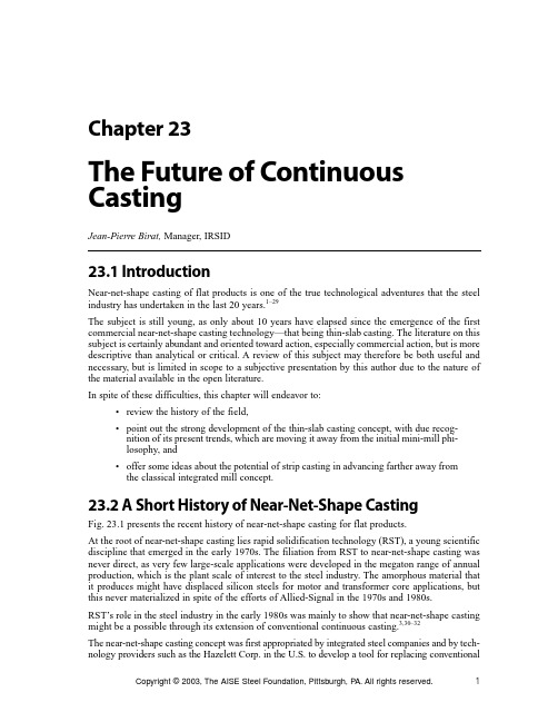
Copyright © 2003, The AISE Steel Foundation, Pittsburgh, P A.All rights reserved.123.1 IntroductionNear-net-shape casting of flat products is one of the true technological adventures that the steel industry has undertaken in the last 20 years.1–29The subject is still young,as only about 10 years have elapsed since the emergence of the first commercial near-net-shape casting technology—that being thin-slab casting. The literature on this subject is certainly abundant and oriented toward action,especially commercial action,but is more descriptive than analytical or critical. A review of this subject may therefore be both useful and necessary,but is limited in scope to a subjective presentation by this author due to the nature of the material available in the open literature.In spite of these difficulties,this chapter will endeavor to:•review the history of the field,•point out the strong development of the thin-slab casting concept,with due recog-nition of its present trends,which are moving it away from the initial mini-mill phi-losophy,and•offer some ideas about the potential of strip casting in advancing farther away from the classical integrated mill concept.23.2 A Short History of Near-Net-Shape CastingFig. 23.1 presents the recent history of near-net-shape casting for flat products.At the root of near-net-shape casting lies rapid solidification technology (RST),a young scientific discipline that emerged in the early 1970s. The filiation from RST to near-net-shape casting was never direct,as very few large-scale applications were developed in the megaton range of annual production,which is the plant scale of interest to the steel industry. The amorphous material that it produces might have displaced silicon steels for motor and transformer core applications,but this never materialized in spite of the efforts of Allied-Signal in the 1970s and 1980s.RST’s role in the steel industry in the early 1980s was mainly to show that near-net-shape casting might be a possible through its extension of conventional continuous casting.3,30–32The near-net-shape casting concept was first appropriated by integrated steel companies and by tech-nology providers such as the Hazelett Corp. in the U.S. to develop a tool for replacing conventionalChapter 23The Future of Continuous CastingJean-Pierre Birat, Manager, IRSIDCasting VolumeFig.23.1 A historical perspective on the near-net-shape casting of flat products.continuous casting and the roughing stands of the hot strip mill (HSM) on a quantitative production basis,i.e.,equipment for equipment. The idea was to change only the technology employed and con-tinue with business as usual in other areas of mill management. Casting between belts,a technology that had been quite successful in the nonferrous business,looked like it had the potential to fulfill this rather demanding agenda.After much money and time was spent on the concept in the U.S. (Hazelett,Nucor,U. S. Steel, Bethlehem Steel),in Japan (Kawasaki Steel,Nippon Steel) and in Europe (Ugine,Krupp Stahl),it became clear that the technology could not be brought up to the expected level,and it was all but abandoned.3At the same time that the twin belt technology was being pushed forward,the concept of strip cast-ing was being picked up as a working subject by a large number of research organizations all over the world. It was both a declaration of faith in the potential of innovation by the steel industry and a somewhat naive underestimation of the technological problems to be overcome. The agenda in this case was to do away almost completely with hot rolling and to replace the hot side of the steel mill with steelmaking and casting facilities. The concept today,after 20 years of research and development,is just emerging as commercially viable.Last in this historical schedule,but certainly not least in practical importance,is the thin-slab cast-ing concept launched by German equipment manufacturers in the 1980s. They were able to reach satisfactory results quickly and to commercialize the process at a time when the U.S. was in need of more steelmaking capacity,and when newcomers to the steel business there were bold enough to employ this technology to start their new businesses. Thin-slab casting today has turned out to be tremendously successful.The fascination with and success of near-net-shape casting technologies are certainly not limited to process and engineering viewpoints,but are closely related to the core business of the steel industry. One important aspect of this business connection is explained on the graph in Fig. 23.2, where the cost of building a greenfield steel mill is plotted on the vertical axis versus the specific cost per ton of annual steel capacity. For newcomers interested in commodity flat rolled steel pro-duction for a local market,the mini-mill is clearly a more attractive solution than an integrated mill. Integrated mills,which we may call the standard model of steel mills,had been successful since WWII in expanding the steel industry production capacity to meet the exploding demand for steel 2Copyright © 2003, The AISE Steel Foundation, Pittsburgh, PA.All rights reserved.The Future of Continuous CastingFig.23.2Mill models for flat products.due to economic growth in the rebuilt Western economies,as well as in nonindustrialized and non-developed countries. H owever,they require large capacities—several million tons per year—to reap the benefits of economies of scale,and large specific investment levels because of the com-plexity of the hot metal plant and the HSM.In the 1970s and 1980s,the mini-mill,which is a management concept based on matching a well-defined local market with lean production facilities capable of reactivity and flexibility,was look-ing for a technology to migrate from the long product to the flat product field.33–75Thin-slab casting is the technology that made this move possible. North America was the first geopolitical region of the world where the concept was extensively commercialized. It has since been utilized in the Pacific Rim as well as in Europe and in South America.23.3 Thin-Slab Casting76–229A review of thin-slab casting technology should explain why this particular technology was so rapidly successful and how far it has already evolved from the premises set forth 10 years ago by Nucor Steel at Crawfordsville,Ind.68–7523.3.1 Main Features of Thin-Slab CastingOne should initially stress the point that thin-slab casting is a direct extension of conventional con-tinuous casting. This is most certainly the reason why thin-slab casting could be developed into an actual production process in somewhat more than 10 years,which should be considered a short time for the steel industry,where 20 or 30 years are more representative of the time needed to induce a technology quantum leap.76–95Indeed,the world record on casting speed was obtained in Barrows,England,in the 1950s at 47.5 ft/min (14.5 m/min),and the major achievement of thin-slab casting was to make it safe and reli-able to cast at 13.0–19.5 ft/min (4.0–6.0 m/min). Initial solidification of the shell in thin-slab cast-ing,just as in conventional continuous casting,takes place by adding rings of shell to the thin slab, making use of an oscillating mold with a free meniscus,slag lubrication in the mold and continu-ous withdrawal of the product. The technologies needed to achieve reliable thin-slab casting were Copyright © 2003, The AISE Steel Foundation, Pittsburgh, PA.All rights reserved.3Casting Volumeall already imagined and had only to be further developed to reach the specific goals of thin-slab casting.Thin-slab casting is based on a number of complementary processes that must be applied together in order to establish a coherent production route:•Thin-slab casting will produce either thin slabs,from 1.5 to 2.75 inches (40 to 70 mm) in thickness,or medium-thickness slabs,from 3 to 6 inches (80 to 150 mm).•In-line reduction is then applied,either to the shell with a liquid core or to the solid slab.•The as-cast material must be homogenized in temperature and kept at the required enthalpy level in a special furnace type designed to accommodate its unusuallength,either a tunnel furnace or a hot-coiler.•Hot rolling can then be performed on the equivalent of finishing stands of a hot strip mill (HSM),or on a leaner mill such as a Steckel mill or a hot planetary mill. 23.3.2 Steelmaking for Thin-Slab CastingSteelmaking technologies,upstream from the caster,also need to be discussed in connection with thin-slab casting,as they are absolutely vital to the equilibrium of the whole process route (see Fig.23.3).The most common steelmaking route is the electric arc furnace meltshop,in that EAF technology has matured after important developments in the 1980s and still holds potential for further devel-opment.Scrap is the normal feedstock of the EAF,although people are recurrently nervous in the northern hemisphere about its availability,its price and its level of purity regarding tramp elements. It is com-plemented by small amounts of DRI or HBI,a favorite subject of conferences,which rather should be more concerned about scrap if they were to reflect the real importance of EAF raw materials.100 Thin-slab casting and an EAF are thus central to the new standard mini-mill,with CSP (Compact Strip Production) holding a large majority of the market share due to its being the first commeri-cialized process.101–124Fig.23.3 Processes upstream of the thin-slab caster.4Copyright © 2003, The AISE Steel Foundation, Pittsburgh, PA.All rights reserved.。
连铸国外常用连铸结构工艺流程图的英文摘要

连铸国外常用连铸结构工艺流程图的英文摘要English: The commonly used continuous casting structure process flow chart in foreign countries includes the following steps: 1. The ladle is placed on the turret of the continuous casting machine, the tundish is adjusted to the casting height, and the mold parts are installed and adjusted. 2. The molten steel is poured into the tundish, and the steel flow control device is used to control the flow rate and avoid turbulence. 3. The molten steel passes through the submerged entry nozzle and enters the mold, where it solidifies and forms a shell.4. The solidified shell is continuously withdrawn by the withdrawal system, and the internal temperature is controlled to ensure complete solidification.5. The billet or slab is cut to the required length, and the process is completed.中文翻译: 国外常用的连铸结构工艺流程图包括以下步骤:1. 将钢包放置在连铸机的转塔上,调整中间包至浇铸高度,并安装调整模具部件。
连铸机毕业设计论文

摘要高效连铸通常定义为五高:即整个连铸坯生产过程是高拉速、高质量、高效率、高作业率、高温铸坯。
本设计的内容主要包括简单的介绍了我国及世界铸钢技术的发展轨迹及未来连铸技术的发展方向。
简单的介绍连铸机机型特点及选择使用的方法。
本设计主要是从提高连铸机拉速和提高连铸机作业率两方面着手。
从而提高连铸机设备的坚固性、可靠性和自动化水平,达到长时间的无故障在线作业,提高连铸机作业率水平。
连铸工序采用多项先进技术,使得单线布置紧凑,使产品质量、生产成本、生产效率得到了优化。
关键词:连铸机型方坯连铸铸坯质量结晶器优化AbstractEfficient continuous casting is usually defined as five high : that the entire billet production process is high speed, high quality, high efficiencyhigh operating rates. High temperature slab.The design covers the brief introduction to China and the world steel technology development path and future direction of continuous casting technology. Brief characteristics of continuous casting machine models and select the method used. This design is mainly to increase speed and improve the continuous casting machine continuous casting machine of two aspects Continuous casting machine equipment to enhance the robustness, reliability and automation level, to achieve long trouble-free online operations and increase the rate of horizontal continuous casting machine operation. Continuous casting process uses a combination of advanced technology, making single compact layout, product quality, production costs, production efficiency has been optimized.Key words:continuous casting billet Slab quality Mold Optimization第一章绪论1.1毕业设计的目的毕业设计是在机械设计与制造专业理论教学之后进行的实践性教学环节,是对所学知识的一次总检验,是走向工作岗位前的一次实战演习,其目的是:1、综合运用本专业所学课程的理论和实践知识,通过设计一个零件的外观和结构,绘制出三维立体图,完成装配图,培养和提高学生独立的工作能力。
连铸机结晶器振动装置设计
摘要结晶器是连铸机的心脏部件。
它的主要作用就是对结晶器中的钢水提供快速而且均匀的冷却环境,促使坯壳的快速均匀生长,以形成质量良好的坯壳,保证连铸过程正常而稳定的进行。
在浇注钢水时,若结晶器静止不动,坯壳容易与结晶器内壁产生粘结,这就增大了拉坯时的阻力,导致出现坯壳“拉不动”或者钢水被拉漏事故发生,很难进行浇注。
而当结晶器以一定的规律振动时,这就能使其内壁获得比较良好的润滑条件,从而减少了摩擦阻力又能防止钢水和结晶器内壁的粘结,同时还可以改善铸坯的表面质量,因此结晶器振动装置具有重要的作用。
本文通过对连铸发展历史,以及结晶器振动技术的发展和结晶器振动方式的改进进行了阐述,提出了电液伺服装置驱动,并对其振动规律及工作原理做出了分析。
然后绘制了机械简图,并对其工艺参数和运动参数进行了分析计算,最终完成了本次设计。
本文主要的设计内容包括:1.结晶器振动正弦参数的确定通过负滑脱量、频率和周期、结晶器运动的速度和加速度以及负滑脱时间的计算,来确定铸坯的工艺参数。
2.结晶器振动装置机械计算设计校核了双摇杆机构的主要部分,并根据经验推出机架结构。
3.结晶器振动装置伺服系统的设计计算由系统所需动力选择恰当的液压缸及液压泵。
并对系统的辅助原件进行了计算和选择,同时提出了同步回路电液伺服系统。
4.结晶器振动装置的三维设计关键词:连铸;结晶器;振动装置;振动规律;电液伺服装置AbstractThe mould is the heart part of continuous casting machine. Its main role is to mould the steel in providing rapid and uniform cooling environment, promote the rapid and uniform shell growth, to form a good quality of billet shell, guarantee the normal and stable for continuous casting process. In pouring molten steel in crystallizer, motionless, shell and the mold wall to produce a cohesive, which increases the casting the resistance, led to the emergence of billet shell" sticks" or molten steel is breakout occurs, it is difficult to cast. When the mould in regular vibration, which can make the inner wall is obtained in comparison with good lubrication condition, thereby reducing the friction resistance and can prevent the molten steel and the inner wall of the crystallizer is bonded, but also can improve the surface quality of billet crystallizer vibration device, therefore has an important role.Based on the history and development of continuous casting crystallizer vibration technique, development and improvement of crystallizer vibration mode undertook elaborating, put forward to the electro-hydraulic servo device driver, and the vibration regularity and working principle are analyzed. Then draw the mechanical model, and the process parameters and motion parameters are analyzed and calculated, the final completion of the design.The main design content includes:1.crystallizer vibration sinusoidal parametersThrough the negative slip quantity, frequency and cycle, mold movement velocity and acceleration and negative strip time calculation, to determine the process parameters of casting billet.2.The device of vibration of crystallizer mechanical calculationDesign of the double rocker mechanism the main part, and according to the experience introduction of frame structure.3.The device of vibration of crystallizer of servo system designBy the system the power required by the proper selection of hydraulic cylinder and hydraulic pump. And the system of auxiliary components were calculated and selected, simultaneously proposed synchronous electro-hydraulic servo system.4.dimensional design of crystallizer vibration deviceKey words: continuous casting ;crystallizer ;vibration device; vibration; electro-hydraulic servo device目录摘要 (I)Abstract (II)第一章绪论 (1)1.1什么是连铸 (1)1.2国内连铸的重要性 (1)1.3中国连铸发展的主要成就 (2)1.4世界连铸技术的发展及我国存在的差距 (3)1.5连铸机振动系统应注意的部分问题 (4)第二章结晶器振动技术 (6)2.1结晶器振动技术发展的历史 (6)2.2连铸机结晶器振动简介 (6)2.3结晶器振动规律的演变 (7)2.4结晶器振动和润滑的关系 (10)第三章结晶器振动方案的选择 (14)3.1本课题研究的目的 (14)3.2课题研究内容 (14)3.3设备发展状况 (15)3.4周边设备简介 (15)3.5技术方案介绍 (15)3.6 振动机构的选择 (19)第四章结晶器正弦振动的参数分析 (22)4.1负滑脱量计算 (22)4.2频率与周期 (22)4.3结晶器的运动速度和加速度 (23)4.4负滑脱时间的确定 (24)第五章结晶器振动装置机械设计 (26)5.1受力分析 (26)5.2强度校核 (27)5.2.1轴Ⅰ的校核 (27)5.2.2轴Ⅱ的校核 (30)5.3轴承校核 (34)第六章结晶器振动装置伺服系统的设计 (35)6.1控制方案 (35)6.2设计计算 (36)6.3液压缸设计计算 (36)6.3.1油缸的设计原则 (36)6.3.2油缸的设计 (37)6.3.3油缸参数计算 (37)6.4泵的选择计算 (39)6.4.1泵的选择计算原则 (39)6.4.2系统流量计算 (39)6.4.3流量计算 (39)6.4.4泵的参数计算 (40)6.5阀的选择计算 (40)6.6辅助元件的选择计算 (42)6.6.1管路 (42)6.6.2蓄能器的选择 (44)6.7油箱的设计计算 (45)6.7.1油箱设计原则 (45)6.7.2油箱参数设计计算 (45)6.7.3油箱容量的计算 (46)6.7.4油箱内工作介质体积估算 (46)6.8系统发热功率计算 (46)6.8.1液压泵的功率损失 (46)6.8.2阀的损失功率 (46)6.8.3管路以及其它功率损失 (47)6.9过滤器的选择 (47)6.10液压工作介质的选取 (48)第七章三维建模 (49)7.1零部件三维设计 (49)7.1.1结晶器振动装置固定台 (49)7.1.2结晶器振动装置活动台 (49)7.1.3连杆1 (50)7.1.4连杆2 (50)7.1.5心轴 (51)7.1.6轴承 (51)7.1.7挡圈 (51)7.1.8轴承端盖 (52)7.1.9阻尼器气囊 (52)7.1.10进水管 (52)7.1.11阻尼器进气管道 (53)7.1.12环状活塞杆头 (53)7.1.13阻尼器支架 (54)7.1.14液压缸 (54)7.2总装配图 (55)总结 (56)致谢 (57)参考文献 (58)第一章绪论1.1什么是连铸连铸即为连续铸钢(英文,Continuous Steel Casting)的简称。
钢铁是怎样炼成的 经典语段英文赏析

钢铁是怎样炼成的经典语段英文赏析How Steel is Made: A Classic English Paragraph AppreciationSteel, a versatile and vital material in our modern world, has a fascinating story of how it is made. From its humble beginnings as iron ore to its transformation into durable and strong steel, the process of steel production involves complex techniques and precise craftsmanship. In this article, we will delve into the journey of how steel is made and explore some classic English paragraphs that beautifully describe this process.1. Raw Materials: Iron Ore and CokeBefore steel can be produced, the primary ingredients - iron ore and coke - must be gathered. Iron ore, in its raw form, is extracted from mines and then transported to steel mills. The iron ore is usually crushed and sorted into smaller pieces to enhance its efficiency in the subsequent stages of production. Coke, which is derived from coal, serves as a fuel source to provide the necessary heat for the chemical reactions that occur during steelmaking."The journey of steel begins with the union of iron ore and coke, a marriage of raw materials that sets the foundation for its magnificent transformation."2. Blast Furnace and SmeltingOnce the iron ore and coke are ready, they are introduced into a colossal structure called a blast furnace. This towering furnace stands tall, akin to a modern-day industrial marvel, exerting its power to melt the iron ore andinitiate the smelting process. As temperatures rise within the blast furnace, the iron ore reacts with the carbon in the coke, resulting in the reduction of iron oxide into molten iron."Within the fiery belly of the blast furnace, a symphony of heat and chemical reactions unfolds, as iron ore surrenders its impurities and transforms into a molten river of iron."3. Steelmaking: The Art of AlloyingWhile molten iron marks a significant milestone in the steelmaking process, it is not yet steel. To attain the desired properties of steel, alloying elements such as manganese, chromium, and nickel are added to the molten iron. These alloying elements bestow steel with unique characteristics, including strength, corrosion resistance, and heat resistance. Through meticulous measurements and precise calculations, the composition of these alloying elements is carefully adjusted to achieve the desired outcome."Like a skilled artist, the metallurgist delicately introduces alloying elements into the molten iron, carefully balancing each addition to create a symphony of strength and versatility - true steel in its nascent form."4. Continuous Casting: Shaping the FutureOnce the molten steel has been alloyed to perfection, it is ready to be shaped. The process of continuous casting allows this molten metal to be poured into molds, where it solidifies into long, slender strands known as billets. These billets serve as the building blocks for the wide array of steel products we encounter in our daily lives, such as rods, beams, and sheets."The molten steel, once a fluid masterpiece, takes its final form as it gracefully pours into molds, crafting its destiny as a versatile building block for civilization's endless pursuits."5. Heat Treatment and Quality AssuranceTo ensure the strength and durability of steel, it undergoes heat treatment processes such as tempering, quenching, and annealing. These treatments refine the steel's internal structure, aligning its crystal lattice and fortifying its mechanical properties. Furthermore, rigorous quality control measures are put in place throughout the steel production process to guarantee consistent quality and adherence to industry standards."Tempered by heat and tested with remorseless scrutiny, steel emerges triumphant, its physical integrity fortified, embodying the resilience and reliability we entrust our world with."In conclusion, the journey of how steel is made is a testament to human ingenuity and craftsmanship. From the marriage of raw materials to the orchestration of precise chemical reactions, the process of steel production is a harmonious blend of science and art. Through classic English paragraphs, we can appreciate the beauty in the description of this process, elevating steelmaking into a work of literature.。
- 1、下载文档前请自行甄别文档内容的完整性,平台不提供额外的编辑、内容补充、找答案等附加服务。
- 2、"仅部分预览"的文档,不可在线预览部分如存在完整性等问题,可反馈申请退款(可完整预览的文档不适用该条件!)。
- 3、如文档侵犯您的权益,请联系客服反馈,我们会尽快为您处理(人工客服工作时间:9:00-18:30)。
The Development of Continuous Casting【连铸】Continuous CastingFrom the Making, Shaping and Treating of Steel by William,McGraw—Hill Companies, Inc., 2002The Development of Continuous CastingContinuous casting was developed very rapidly after the Second World War. Steel-producers arc today generally convinced that continuous casting is at least as economical as ingot production and can match the quality of the latter across much of the production spectrum for high-quality steels. Continual development of the technique aimed at improved steel characteristics is leading to increasing adoption of the process in works producing special high-grade steels. The reasons for continuous-casting systems are:(1) lower investment outlay compared with that for a blooming train(mini-steelworks);(2) about 10% more productivity than with conventional ingot-casting;(3) high degree of consistency of steel composition along the whole length of the strand; better core quality, especially with flat strands; high inherent surface quality, leading to savings on an otherwise expensive surfacing process;(4) high degree of automation;(5) friendlier to the environment;(6) better working conditions.Types of InstallationThe first continuous-casting plants were aligned vertically; however, with larger cross-sections, increasing strand-length, and, above all, with increasing pouring-rates this type of construction leads to unreasonable building-heights. These factors also lead to a considerable increase in the length of the liquid phase which has metallurgical effects. The length of the liquid phase in a continuously-cast strand is determined by the following formula:L=D2/4x2VcWhere D =strand thickness (mm)x = solidification characteristic (mm / min1/2)These values amount to 26~33 for the whole cooling length.Vc = casting rate (m /min)Efforts to reduce building-height first led to continuous-casting systems in which molten metal passed into a vertical mould and solidified completely before being bent or where the strand has been in the liquid phase and later to the bow-type installation which has a curved mould and is the system most used today. Vertical systems and those in which the strand is bent when completely solidified have long straight liquid phases and can lead to unacceptably high capital outlay.However, these systems have metallurgical advantages from the point of view of maintenance. A vertical system in which the strand is bent while still in the liquid phase has the advantage that the building need not be as tall as when the strand is bent after solidification; however, the liquid-phase bending system requires higher initial outlay and greater maintenance costs. The bow-type system represents a compromise between the costs of capital outlay and of maintenance and what can be achieved metallurgic ally.Continuous-casting is suitable for the production of almost any cross-section imaginable; square, rectangular, polygonal, round, and oval sections are all available. There are also some instances of preliminary sections for tubes and slabs, blooms, and billets. Sections with a breadth /thickness ratio greater than 1.6 are normally described as slabs. Billet-machines produce square or nearly-square, round, or polygonal cross-sections up to 160mm across. Larger sections and those with a breadth /thickness ratio less than 1.6 are cast in bloom-machines. Billets nowadays normally produced in this way range from 80 x80 to 300 x300 mm, and slabs are 50 - 350mm thick and 300 - 2500 mm wide.Continuous-casting output-rates have risen sharply, especially in the last few years. This is essentially because of increase in the breadth of the strand and in casting rate. The following outputs have been exceeded per section per minute:slabs 5 tonesblooms 1 tonesbillets 350 kgFinally, we should mention horizontal continuous-casting systems which are already used for non-ferrous metals and cast iron and which are being further developed for steel. R. Thieimann and R. Steffen have produced a comprehensive report about the state of development of horizontal continuous-casting systems for producing billets from unalloyed and alloy steels. Horizontal continuous-casting systems have three important advantages over conventional continuous-casting system:(1) low height and cost of building;(2) simple means of protecting the melt against reoxidatioin;(3) no strand deformation because the ferrostatic pressure is much lower.Casting TechniqueMolten steel is poured from a casting ladle via a tundish into an openwater-cooled copper mould. At first the bottom of the mould is closed off by a starting-bar, which then leads transport of the hot strand from the mould into the continuous withdrawing rolls. The strand, which starts to solidify in the mould, passes through a cooling system before it finally reaches the withdrawing rolls, whereupon the hot strand takes over transport. The starting-bar is separated from the hot strand before or after it reaches the parting device. The latter, which may either be aflame-cutter or hot shears, moves at the same rate as the hot strand and cuts it into the lengths required.The purpose of the tundish is to feed a defined quantity of molten steel into one or more moulds. This can be done by using nozzles controlled by stoppers, slide-gates, or other means. The tundish may initially be cold, warm, or hot according to the nature of its refractory lining. Where difficult steels are processed the pouring stream is protected against oxidation between the submerged boxes. The mould not only forms the strand section but also extracts a defined quantity of heat, so that the strand shell is strong enough for transport by the time it reaches the mould-outlet. The mould may be made from copper tube or hard enable copper alloy, depending on the shape and size of the strand to be cast. As a rule, tubular moulds tire used for smaller sections. The interior surface of the mould may be coated with chronic or molybdenum to reduce wear and to suit heat-transfer from the alloy being cast. The mould is tapered to match steel-shrinkage and casting-rate and the type of steel concerned. Moulds used today range from 400 to 1200 mm in length overall, but their usual length is between 700 and 800 mm. The problem of steel adhering to the mould-sides is usually countered by oscillating the mould sinusoidally relative to the strand and by adding lubricant (oil or casting flux} in an attempt to cut friction between the mould and the steel. The lubricant, particularly casting-flux, has anadditional metallurgical function. The choice of lubricant depends on the qualities required and the casting conditions; it is particularly important that casting-flux should be chosen to match the quality-programme precisely.The level of steel in the mould may be controlled manually or by an automatic system. Either method may be used to keep the level constant or to match the incoming molten steel, i. e. to accommodate variations in casting rate. Manual control is affected via the stopper in the tundish or by varying the output rate. An automatic control system may meter radioactivity or infrared radiation or measure temperature via a probe in the mould wall to determine the steel-level and compensate any changes by actuating the stopper-mechanism (for constant pouring rate) or controlling the speed of the withdrawing rolls (varying casting rate).The type of starting-bar used for continuous-casting depends on the type of installation. Rigid starting-bars can be used in vertical systems, while articulated dummy bars or flexible strip have to be used in bowed installations. The starting bar can be connected to the hot strand in different ways, one is by welding the fluid steel using a jointing element (flat slab, screw, or fragment of rail) which is soluble in the starting-bar; another is by casting the connector in a specially shaped head in the dummy bar in a way that enables it to be released by unlatching.The thickness of the solidified strand shell on leaving the mould depends first of all on how long the steel is in contact with the mould, but it also depends on the specific thermal conductivity of the mould and on the amount of superheat that steel has when it enters the mould. It can be determined with fair accuracy using the following parabolic formula:C=x. Twhere C is the thickness of the strand shell (mm)x is the solidification characteristic (mm/min1/2)t is the solidification time (min)The solidification characteristic in and near the mould lies between 20 and 26, depending on the operating conditions; for the secondary cooling-area the figure is 29 -33. The thickness of the solidified strand shell on leaving the mould is about 8 10% of the strand-thickness, depending on casting rate. A secondary cooling-area under the mould speeds up completion of the solidification process. The coolant usually is water but a water / air mixture or compressed air is also sometimes used. The secondary cooling area is divided into several zones to suit coolant flow rates. The necessary quantity of water is sprayed over the entire strand by spray-bars. The ferrostaticpressure may be so high in relation to the strand cross-section and the casting rate that the strand has to be supported to prevent buckling. The equipment for this is expensive in plants producing blooms and especially slabs.Process ControlFor productivity and quality reasons there is a trend in modern steelmaking to transfer time-consuming operations, such as temperature adjustment, deoxidation and alloying, from the furnace to the ladle treatment stations. These treatments are particularly important where the continuous casting process is involved because temperature and composition must closely be controlled.The temperature control of molten steel as it enters the mould needs to be more accurate in the continuous casting process than in conventional casting. Too high a superheat can cause breakouts or a dendritic structure, which is often associated with poor internal quality. On the other hand, too low a temperature may cause casting difficulties due to nozzle clogging and result in dirty steel. The steel temperature in the tundish normally lies between 5 and 20℃ above the liquids for slab casting and between 5 and 50℃ for billet or bloom casting. This differential depends on steel grade and, for example, is about 45t for stainless steel slab casting from small furnaces.In order to keep the steel temperature within the prescribed limits during the whole cast, temperature uniformity in the ladle is of paramount importance. Stirring is required before casting in order to destroy any temperature variations in the ladle, and rinsing is sometimes used. The heat is flushed with either nitrogen or argon, injected by means of a porous plug at the bottom of the ladle or through a hollow stopper rod at a separate rinsing station.Control of chemical composition can be performed during vacuum or rinsing treatments. On the basis of the analysis of a sample or of an electromotive force oxygen activity measurement made after homogeneity of the metal is attained, trimming additions can be calculated to ensure correct deoxidation. The best way to introduce trim deoxidants is at a high velocity (powder injection with inert gas, wire feeding or bullet shooting) while stirring the bath. Decreasing the need for alloys by careful exclusion of furnace slag from the ladle simplifies trimming. Vacuum treatment is versatile and useful to achieve for good ladle metallurgy. Low-pressure treatment, however, is the only way to remove hydrogen before casting or to decarburize to extremely low levels.Mould-level controlThe most vital part of the control of a continuous casting machine is to ensure that thewithdrawal of the cast and the partially-cooled billet is such as to keep the liquid level in the mould constant (within a few centimeters). This is done in two ways.(1) The tundish is weighed and the rate of feed to the tundish from the ladle varied automatically to keep the total tundish weight constant. In this way the rate of feed from the tundish is constant.(2) The rate of withdrawal of the partially cooled billet is controlled so as to keep the level of liquid steel in the mould roughly constant.In the early days of continuous casting the level of the top of the liquid steel in the caster was maintained constant by an operator viewing it and adjusting the tundish stopper accordingly. It is now normal to have a means of finding the level using a measuring instrument and automatically adjusting the level. The table below lists several ways in which the level is detected. Two of them, the gamma-ray (radioactive) and the infrared methods will be described in detail.The operation is self-evident from this diagram. The infrared device was developed in order to avoid the use of powerful radioactive isotopes. The detector views the junction of the metal level with the back wall of the mould. As the metal level rises within the field of view more radiation is received by the single photocell and an increased output is obtained. Special provisions are made to compensate for interruption of the view of the metal. The photocell unit receives the infrared radiation and provides an electrical signal to the control unit, which is in turn connected to the operator's unit and the casting-machine drives. The operator can select automatic or manual control and he receives indication of the operating rod from signal lamps. The radiation emitted from the liquid steel is collimated through a slotted mask and then focused on to a photo detector by a cylindrical lens. The light is filtered to eliminate radiation below a wavelength of 1 mm, so reducing interference from ambient light and oil flames.The entire system is duplicated within the had with two detectors and two fit beams normally arranged to view either side of the steel stream. It is possible to adjust the spacing between the two areas seen by the photocells by changing the slot spacing in the mask.There are three photo detectors fitted for each channel: the first measures the metal level using the beam described above; the second receives no light and enables temperature drift compensation; and the third looks through the slot at a small region above the normal metal level and between the main beam and the metal stream. Its purpose is to detect the metal stream if it wanders from a central position and is in danger of interfering with the main beam. The balance between the two main beamsand the threshold level of the stream detectors can be adjusted with small potentiometers mounted in the back of the unit.The level signal detected by each channel is fed, after temperature compensation, to a simple circuit which selects the largest signal. Thus the unit always controls on the higher of the two level signals. If the stream-sensing photocell sees that the teeming stream is moving towards the detection beam it blocks the signal and the unit switches to control on the other channel. There is an additional feature that if both channels are blocked together, for example by a fan-shaped metal stream, the unit switches to a memory, equivalent to the fast detected metal level, and prevents a sudden loss of control. As the memory decays the metal level gradually drops allowing the operator ample time to intervene.The unit gives a smooth transition from manual to automatic control by preventing automatic operation if there would be a large jump in withdrawal speed at changeover. It does not provide bumpless transfer when changing from automatic to manual. There is also protection against changing to automatic when there is a cable fault.The control system receives the chosen level signal and, following proportional and integral action, outputs a voltage signal directly to the withdrawal drive unit. The drive creates a withdrawal speed proportional to this voltage signal.Benefits of Continuous CastingSequence of Operations-prior to the development of continuous casting, ingots provided the only starting material in wrought-steel products. The typical sequence of operations from the steelmaking furnace to the rolling mills was:(1) Tapping liquid steel into ingot molds.(2) Transferring ladle to pouring platform and teeming liquid steel into ingot molds.(3) Transferring filled molds to stripping area for ingot removal.(4) Transferring and charging ingots into soaking pits and heating to rolling temperature.(5) Removal of heated ingots from soaking pits and transfer to primary mill for rolling into semi-finished shapes.(6) Transferring semi-finished shapes to subsequent rolling mills.Using continuous casting, the following much shorter sequence of operations is required:(1) Tapping liquid steel from a steelmaking furnace into a ladle.(2) Transferring the ladle to a casting platform and continuously casting liquid steel into semifinished shapes.(3) Transferring the semi-finished shapes to rolling mills.The benefits derived from the shorter sequence of operations provided the main impetus for the adoption of continuously casting; increased yield; improved product quality; energy savings; less pollution; and reduced costs.Yield Increased yield from liquid steel in the ladle to the semi-finished rolled shape results from a reduction in scrap generation in three areas: the primary rolling mill; the pouring operation; and ingot heating. The major contribution to the improved yield is the absence of crop losses corresponding to the ingot top and bottom location when an ingot is rolled in the primary mill. Reduction in yield losses associated with the pouring operation includes "short" ingots, ingot butts and general pit scrap. Scaling losses associated with ingot heating in the soaking pit are also avoided.Quality Metallurgical quality improvements include less variability in chemical composition and solidification characteristics. In addition to improved segregation characteristics of carbon, sulfur and alloying elements across the section of a continuously cast shape, there is also less variability along the length of the cast shape. (In casting a heat into ingots there are a multitude of individual ingots each with their associated vertical segregation and structural variability, whereas a continuous cast strand is not only as one ingot but also an ingot which has less variability in a vertical direction.) In modern continuous casting, the surface quality of the cast shape is superior to that of a semi-finished rolled shape with respect to surface defects such as seams and scabs, and, consequently, conditioning requirements and yield losses are minimized. A majority of continuously cast steels can be further processed without any conditioning. Thus, an improved, more uniform finished product can be obtained with fewer internal and surface defects.Energy Energy savings are achieved with continuous casting because of the elimination of the energy-consuming steps in the ingot process. These include fuel consumption in soaking pits and the electric power requirements for operating the primary rolling mills. Energy is also indirectly saved through the increased yield which requires the production of less raw steel for a comparable quantity ofsemi-finished product. !n addition to these savings, a practice in which hotcontinuously cast shapes are charged directly into a heating furnace in the finishing mills is receiving attention. Thus the sensible heat of the cast product is conserved.Pollution Continuous casting reduces pollution through the elimination ofingot-processing facilities such as soaking pits.Costs Both capital and operating costs are reduced with the installation of continuous casting in comparison with ingot processing. Capital assets savings are attributable to the elimination of the additional equipment required for ingot processing. Operating cost savings are primarily the result of lower manpower requirements and higher yields.SteelmakingSteelmaking practices for continuously cast steels are, with certain exceptions, similar to those employed for ingot steels whether produced in the electric furnace or basic oxygen converters. There are two major exceptions:(1) temperature control;(2) deoxidation practice.Temperature Control Temperature control is more critical than in ingot production. The tapping temperature is generally higher to compensate for heat losses associated with the increased transfer time to a caster and must be maintained within closer limits to avoid mold "breakouts", if the temperature is too high or premature freezing in the tundish nozzles, if the temperature is too low. Casting temperature can also affect the crystallization structure of the cast product. Optimum structures are developed with low superheats which should be uniform throughout the entire cast. To meet this objective, temperature homogenization practices are employed. One practice widely employed is to stir the metal in the ladle by the injection of a small quantity of argon through porous plugs located in the bottom the ladle, or a lance which is lowered into the ladle.Dcoxidation Continuously cast steel must be fully deoxidized (killed) to prevent the formation of blowholes or pinholes at or close to the surface of the cast product which cause seams in subsequent rolling operations. Depending on the grade of steel and product applications, either of two practices is employed:(1) silicon deoxidation with a small addition of aluminum for coarse grain steels;(2) aluminum deoxidation for fine grained steel. Silicon-killed steels are easier to cast than aluminum killed steels because deposits of alumina in the tundish nozzle,which cause nozzle blockage, are avoided. For high-quality products, it is becoming a common practice to employ a ladle refining practice prior to casting.连铸连铸的发展二战之后,连铸发展非常迅速_今天钢铁生产者普遍相信连铸至少和模铸一样在经济上是合理的,并且能与大部分高质量钢的生产系列相匹配。