DIN 17022-5-2000 钢铁材料热处理.热处理方法.第5部分表面硬化
《金属材料与热处理(第七版)》第五章钢的热处理课件
一、表面热处理
钢的表面热处理是指仅对钢件表面进行热处理,以改 变表面层组织,满足使用性能要求的热处理工艺。
表面淬火是表面热处理中最常用的方法,是强化材料 表面的重要手段。
目前,表面淬火的方法很多,如火焰加热表面淬火、 感应加热表面淬火、电接触加热表面淬火、激光加热表面 淬火等。生产中最常用的方法主要是火焰加热表面淬火和 感应加热表面淬火。
(5)钢的淬火缺陷
2. 回火 回火是将淬火后的钢重新加热到Ac1点以下的某一温度,
保温一定时间,然后冷却到室温的热处理工艺。
(1)回火时的组织转变
钢(45钢)的回火组织 a)回火马氏体 b)回火屈氏体 c)回火索氏体
40钢的力学性能与回火温度的关系
(2)回火的分类及应用
§5-4 钢的表面热处理与化学热处理
化学热处理的过程示意图
2. 钢的渗碳 钢的渗碳是将钢件置于渗碳介质中加热并保温,使
碳原子渗入工件表层的化学热处理工艺。 根据渗碳介质的工作状态,渗碳方法可分为固体渗
碳、盐浴渗碳和气体渗碳三种,应用最广泛的是气体渗 碳。
气体渗碳是将工件置于气体渗碳剂中进行渗碳的工 艺。
气体渗碳示意图
一般零件渗碳后,其表面含碳量控制在0.85%~1.05%, 含碳量从表面到心部逐渐减少,心部仍保持原来的含碳量。 图示为低碳钢渗碳后缓冷的渗碳层显微组织,图中渗碳层 的组织由表面向中心依次为过共析组织、共析组织、亚共 析组织(过渡层),中心仍为原来的亚共析组织。
钢在加热和冷却时的临界点
2. 奥氏体的形成
共析钢中奥氏体形成过程示意图 a)形核 b)长大 c)残余Fe3C溶解 d)均匀化
如果在形成奥氏体后继续升温或延长保温时间,
DIN标准译文
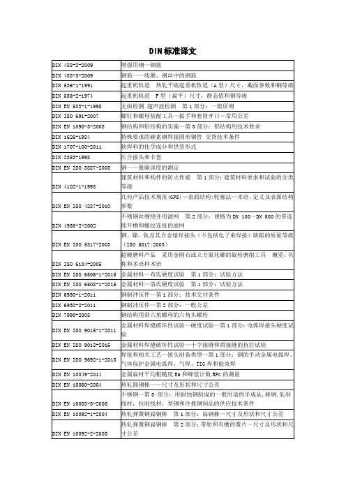
DIN EN 15856-2010
无损检测—声发射—周围充满液体的金属内腐蚀检测用AE试验的一般原理
DIN 16838-2010
管配件用热塑性材料—聚亚苯基砜(PPSU)—通用质量要求和试验
DIN 17022-5-2000
铁基材料的热处理第5部分:表面硬化
起重机—手动控制负载操纵装置(包含修订单A1:2009)
DIN EN 14399-1-2015
预加负荷用高强度螺栓组件—第1部分:通用要求
DIN EN14399-2-2015
预加负荷用高强度螺栓组件—第2部分:预加负荷合适性测试
DIN EN 14399-3-2015
预加负荷用高强度螺栓组件—第3部分:HR系统—六角螺栓和螺母组件
DIN EN 10049-2014
金属扁材平均粗糙度Ra和峰值计数RPc的测量
DIN EN 10060-2004
热轧圆钢棒——尺寸及形状和尺寸公差
DIN EN 10088-3-2005
不锈钢—第3部分:用耐蚀钢制成的一般用途的半成品,棒钢,轧制线材,拉制线材,型钢和冷拨钢制品的供应技术条件
DIN EN 10092-1-2004
DIN 18319-2012
德国建筑合同程序(VOB)—C部分:建筑合同通用技术规范(ATV)—非开挖铺设管道工程
DIN 18320-2012
德国建筑合同程序(VOB)—C部分:建筑合同通用技术规范(ATV)—景观工程
DIN 18321-2012
德国建筑合同程序(VOB)—C部分:建筑合同通用技术规范(ATV)—喷射灌浆施工
DIN EN 13135-2013
起重机—安全—设计—设备要求
钢铁材料的一般热处理,一张表全懂了

热处理是指金属材料在固态下,通过加热、保温、冷却的手段,改变金属材料内部的组织状态,从而获得所需性能的一种热加工工艺。
常见的热处理的方法请参考下表。
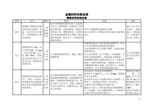
名称热处理过程热处理目的1.退火将钢件加热到一定温度,保温一定时间,然后缓慢冷却到室温①降低钢的硬度,提高塑性,以利于切削加工及冷变形加工②细化晶粒,均匀钢的组织,改善钢的性能及为以后的热处理作准备③消除钢中的内应力。
防止零件加工后变形及开裂退火类别(1)完全退火将钢件加热到临界温度(不同钢材临界温度也不同,一般是710-750℃,个别合金钢的临界温度可达800—900ºC)以上30—50ºC,保温一定时间,然后随炉缓慢冷却(或埋在沙中冷却)细化晶粒,均匀组织,降低硬度,充分消除内应力完全退火适用于含碳量(质量分数)在O.8%以下的锻件或铸钢件(2)球化退火将钢件加热到临界温度以上20~30ºC,经过保温以后,缓慢冷却至500℃以下再出炉空冷降低钢的硬度,改善切削性能,并为以后淬火作好准备,以减少淬火后变形和开裂,球化退火适用于含碳量(质量分数)大于O.8%的碳素钢和合金工具钢(3)去应力退火将钢件加热到500~650ºC,保温一定时间,然后缓慢冷却(一般采用随炉冷却)消除钢件焊接和冷校直时产生的内应力,消除精密零件切削加工时产生的内应力,以防止以后加工和用过程中发生变形去应力退火适用于各种铸件、锻件、焊接件和冷挤压件等2.正火将钢件加热到临界温度以上40~60ºC,保温一定时间,然后在空气中冷却①改善组织结构和切削加工性能②对机械性能要求不高的零件,常用正火作为最终热处理③消除内应力3.淬火将钢件加热到淬火温度,保温一段时间,然后在水、盐水或油(个别材料在空气中)中急速冷却①使钢件获得较高的硬度和耐磨性②使钢件在回火以后得到某种特殊性能,如较高的强度、弹性和韧性等淬火类别(1)单液淬火将钢件加热到淬火温度,经过保温以后,在一种淬火剂中冷却单液淬火只适用于形状比较简单,技术要求不太高的碳素钢及合金钢件。
钢的热处理工艺知识大全

钢的热处理工艺知识大全热处理是将固态金属或合金采用适当的方式加热、保温和冷却以获得所需要的组织结构与性能的工艺。
热处理工艺它能提高零件的使用性能,充分发挥钢材的潜力,延长零件的使用寿命,此外,热处理还可改善工件的工艺性能、提高加工质量、减小刀具磨损。
钢的热处理方法可分为:退火、正火、淬火、回火及表面热处理等五种。
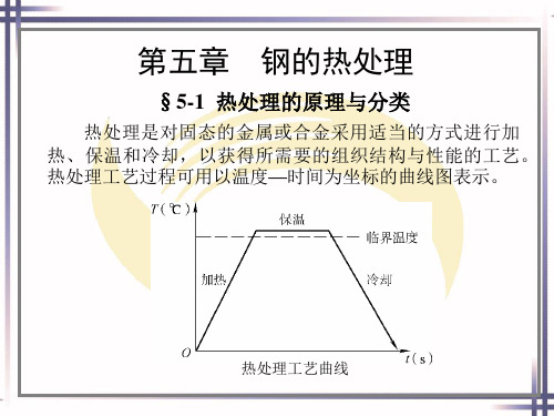
热处理方法虽然很多,但任何一种热处理工艺都是由加热、保温和冷却三个阶段所组成的,因此,热处理工艺过程可用在温度一时间坐标系中的曲线图表示,如下图所示,这种曲线称为热处理工艺曲线。
一、退火将钢加热到适当温度,保持一定时间,然后缓慢冷却(一般随炉冷却)的热处理工艺称为退火。
退火的主要目的是:(1)降低钢的硬度,提高塑性,以利于切削加工及冷变形加工。
(2)细化晶粒,均匀钢的组织及成分,改善钢的性能或为以后的热处理作准备。
(3)消除钢中的残余内应力,以防止变形和开裂。
常用的退火方法有完全退火、球化退火、去应力退火等几种。
(1)完全退火完全退火是将钢加热到完全奥氏体化(AC3 以上30〜50C),随之缓慢冷却,以获得接近平衡状态组织的工艺方法。
在完全退火加热过程中,钢的组织全部转变为奥氏体,在冷却过程中,奥氏体变为细小而均匀的平衡组织(铁素体+珠光体),从而达到降低钢的硬度、细化晶粒、充分消除内应力的目的。
完全退火主要用于中碳钢及低、中碳合金结构钢的铸件、锻件、热轧型材等,有时也用于焊接结构件,过共析钢不宜采用完全退火,因过共析钢完全退火需加热到AS以上,在缓慢冷却时,钢中将析出网状渗碳体,使钢的力学性能变坏。
(2)球化退火是将钢加热到AG以上20〜30C,保温一定时间,以不大于50C /H的冷却速度随炉冷却下来,使钢中碳化物呈球状的工艺方法。
球化退火适用于共析钢及过共析钢,如碳素工具钢、合金工具钢、轴承钢等。
这些钢在锻造加工后进行球化退火,一方面有利于切削加工,同时为最后的淬火处理作好组织准备。
热处理介绍

质量部
热处理简介
三阶段:加热、保温、冷却; 五要素:介质、V加、T、t、V冷
热处理是指金属材料在固态下,通过加热、保温和冷却手段,以获得预期组 织和性能的一种金属热加工工艺。
热处理工艺分类
退火
整体热处 理
正火
淬火
回火
热处理
表面热处 理
火焰淬火
感应加热 热处理
渗碳
化学热处 理
渗氮
碳氮共渗
➢ 降低硬度,提高塑 性,改善切削加工 与压力加工性能;
➢ 细化晶粒,改善力 学性能,为下一步 工序做准备;
➢ 消除冷、热加工所 产生的内应力。
适用于合金结构钢、 碳素工具钢、合金 工具钢、高速钢的 锻件、焊接件以及 供应状态不合格的 原材料;
一般在毛坯状态进 行退火 。
整体热处理
正火
方法
目的
不仅可以作为各种较为重 要结构的最后热处理,而 且还可以作为某些紧密零 件,如丝杠等的预先热处 理,以减小变形。
整体热处理
淬火+低温回火=时效
方法
目的
应用
将 钢 件 加 热 到 80~200 ℃ , 保 温5~20h或更长时间,然后随 炉取出在空气中冷却(空 冷)。
稳定钢件淬火后的组织, 减小存放或使用期间的变 形;
整体热处理
对比
类别
退火
正火 淬火 回火 调质 时效
温度
Ac3+30~50℃ Ac1+30~50℃
Ac1以下 ≥Ac3 ≥Acm ≥Ac3 ≥Ac1
Ac1以下
冷却速度
缓慢冷却(炉冷)
硬度
↓
>退火冷却速度(空冷)
↓
快速冷却
↑
一张图看懂钢铁热处理工艺

操作方法 将钢件加热到80~200度,保温5~20小时或更长时间,然后随炉取出在空气中冷却。 目的
稳定钢件淬火后的组织,减小存放或使用期间的变形; 减轻淬火以及磨削加工后的内应力,稳定形状和尺寸。 应用要点 适用于经淬火后的各钢种; 常用于要求形状不再发生变化的紧密工件,如紧密丝杠、测量工具、床身机箱等。
AS→Fp+Fe3C 共析转变线
碳在铁素体中的溶解度线
钢铁微观组织结构及性能
组织 奥氏体 铁素体 渗碳体 珠光体 莱氏体
退火
力学性能
低硬度、低屈服强度,高塑性 低强度、低硬度、高塑性和韧性 高硬、高强、高耐磨,低塑性和韧性 性能取决于组织形态 高硬、高强、高耐磨
退火工艺可分为:完全退火、扩散退火、等温退火、球化退火、去应力退火及再结晶退火等。
3、钢铁热处理工艺 钢铁是机械工业中应用最广的材料,钢铁显微组织复杂,可以通过热处理予以控制,所以钢 铁的热处理是金属热处理的主要内容。另外,铝、铜、镁、钛等及其合金也都可以通过热处 理改变其力学、物理和化学性能,以获得不同的使用性能。
钢铁热处理工艺制定依据——铁碳相图
铁碳相图中几个重要的点、线和温度
操作方法 将钢件加热到Ac3+30~50℃或Ac1+30~50℃或Ac1以下的温度(可以查阅有关资料)后,一般随炉温缓慢冷却。 目的
降低硬度,提高塑性,改善切削加工与压力加工性能;
细化晶粒,改善力学性能,为下一步工序做准备; 消除冷、热加工所产生的内应力。 应用要点 适用于合金结构钢、碳素工具钢、合金工具钢、高速钢的锻件、焊接件以及供应状态不合格的原材料; 一般在毛坯状态进行退火 。
符号 C E K P S GS(A3) ES(Acm) PSK(A1) PQ
钢的表面热处理
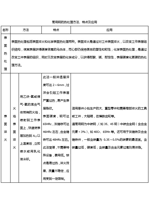
常用钢的热处理方法、特点及应用名称方法特点应用表面热处理表面热处理包括表面淬火和化学表面热处理两种。
表面淬火是通过对工件表面淬火,以改变工作表层组织结构,使其表层获得硬度很高的马氏体,而心部仍保持原来的塑性和韧性;化学表面热处理,是通过改变工件表层的组织,同时又改变表层的化学成分,以获得耐酸、碱、耐蚀性,表层硬度化更硬的热处理方法。
表面淬火火焰表面淬火用乙炔-氧或煤气-氧的混合气体燃烧的火焰,喷射到工作表面上,快速使表层加热到A c3以上温度后,立即喷水或用乳化液冷却。
此法一般淬透层深度可达2~6mm,过深会引起工作表层严重过热,易产生表层裂纹。
表面硬度,钢可达65HRc,灰铸铁可达46HRc左右,合金铸铁可达48HRc左右。
此法简便,不需要特殊设备,费用低。
缺点是易过热,淬火效果、质量不稳定,应用受到一定限制。
适用单件小批生产的大、重型零件和需要局部淬火的工具或工件,大轴辊,在模数齿轮等。
通常用钢为中碳钢,(如35、45钢)中碳合金钢(含合金元素<3%),如40Cr、65Mn等。
还可用于灰铸铁及合金铸铁件,一般含碳量为0.35~0.5%的碳素钢最适宜。
含碳量过低,硬度低;含碳量及合金元素过高则易淬裂。
感应表面加热淬火使用感应器,使工件表层产生强感应电流,迅速将其加热到淬火温度(A c3以上)后,立即喷水冷却,使工件表层淬火。
根据所用电流频率不同,感应加热表面淬火分:工频淬火:50Hz中频淬火:1~10kHz高频淬火:100~1000kHz淬火后变形小,淬透深度易控制,淬火时不易氧化和脱碳;可用于低淬透钢,操作易实现机械化、自动化、生产率高;表层硬度比普通淬火高HRc2~3;疲劳强度、冲击韧性都有所提高,一般工件可提高20~30%;所用电流频率越高,淬透层可越薄,如高频淬火一般为1~2mm,中频淬火一般为3~5mm,工频淬火为≥10~15mm。
缺点是复杂零件比渗碳困难。
通常用于中碳钢(含碳量0.4~0.5%)和中碳合金结构钢,也可用于高碳工具钢和低合金工具钢及铸铁一般零件淬透层深度为其半径101左右时,可获得强度、耐疲劳性和韧性的最好搭配。
金属材料的热处理
固体氰化
常用有色合金的热处理
变形铝合金的热处理
种类
目的
特征
备注
淬火
获得最大程度的过饱和固液体,从而在人工或自然时效后得到高的机械强度
淬火介质有水、油、熔盐及其他液体介质。用水淬火时水温不应超过80℃。零件也可以进行等温淬火。
要正确选择:加热温度,保温时间、加热设备和冷却方法四要素,否则不易达到目的。
是为了提高零件的强度和提高在100℃以下工作时零件的抗蚀性
T5—固溶处理加不完全人工时效
为了得到足够的强度,并保持高的塑性
T6—固溶处理加完全人工时效
为了得到最大的强度和硬度
T7—固溶处理加稳定化处理
为了得到足够的强度和比较高的确良稳定性
T8—固溶处理加软化处理
降低硬度,提高塑性
铜合金的热处理
种类
目的
抗蚀氮化
软氮化
离子氮化
氰化
(透碳氮
共渗)
液体氰化
在一定条件下同时向工件表面渗入碳和氮原子的工艺
氰化可以得到含氮马氏体,耐磨性优良,硬度较高,提高零件的疲劳强度和耐蚀性,且变形较小。
常用于低碳钢、低碳合金钢、中碳钢、中碳合金钢的形状复杂、变形要求小的中小型耐磨工件,具有渗碳和氮化的优点。
目前较多采用气体氰化。扩散层较浅0.02mm~3m,硬度可达66~70HRC
回火分为低温回火、中温回火和高温回火(指500℃~650℃回火)
调质
将工件加热至高于淬火温度10℃~20℃(或20℃~30℃),保温后进行淬火,然后在400℃~720℃进行高温回火
两次加热
调质能得到粒状渗碳体,组织均匀细密,具有良好的塑性、韧性及强度,提高综合机械性能,且可以降低淬火变形和开裂,提高高切削性能。
- 1、下载文档前请自行甄别文档内容的完整性,平台不提供额外的编辑、内容补充、找答案等附加服务。
- 2、"仅部分预览"的文档,不可在线预览部分如存在完整性等问题,可反馈申请退款(可完整预览的文档不适用该条件!)。
- 3、如文档侵犯您的权益,请联系客服反馈,我们会尽快为您处理(人工客服工作时间:9:00-18:30)。
ICS 25.200Wärmebehandlung von Eisenwerkstoffen –Verfahren der Wärmebehandlung –Teil 5: Randschichthärten In keeping with current practice in standards published by the International Organization for Standardization (ISO), a comma has been used throughout as the decimal marker.ContentsPageForeword . . . . . . . . . . . . . . . . . . . . . . . . . . . . . . . . . . . . . . . . . . . . . . . . . . . . . . . . . . . . . . . . . . . . . . . . . . . . . 11Scope . . . . . . . . . . . . . . . . . . . . . . . . . . . . . . . . . . . . . . . . . . . . . . . . . . . . . . . . . . . . . . . . . . . . . . . . . . . . . 12Normative references . . . . . . . . . . . . . . . . . . . . . . . . . . . . . . . . . . . . . . . . . . . . . . . . . . . . . . . . . . . . . . . 23Concepts . . . . . . . . . . . . . . . . . . . . . . . . . . . . . . . . . . . . . . . . . . . . . . . . . . . . . . . . . . . . . . . . . . . . . . . . . . 24Principle of method . . . . . . . . . . . . . . . . . . . . . . . . . . . . . . . . . . . . . . . . . . . . . . . . . . . . . . . . . . . . . . . . . 25Identification of heat treatment condition . . . . . . . . . . . . . . . . . . . . . . . . . . . . . . . . . . . . . . . . . . . . . .26Procedure . . . . . . . . . . . . . . . . . . . . . . . . . . . . . . . . . . . . . . . . . . . . . . . . . . . . . . . . . . . . . . . . . . . . . . . . . 36.1Pretreatment and preparation . . . . . . . . . . . . . . . . . . . . . . . . . . . . . . . . . . . . . . . . . . . . . . . . . . . . . . . . 36.2Austenitizing . . . . . . . . . . . . . . . . . . . . . . . . . . . . . . . . . . . . . . . . . . . . . . . . . . . . . . . . . . . . . . . . . . . . . . 46.3Quenching . . . . . . . . . . . . . . . . . . . . . . . . . . . . . . . . . . . . . . . . . . . . . . . . . . . . . . . . . . . . . . . . . . . . . . . . 66.4Subzero treatment . . . . . . . . . . . . . . . . . . . . . . . . . . . . . . . . . . . . . . . . . . . . . . . . . . . . . . . . . . . . . . . . . 76.5Tempering . . . . . . . . . . . . . . . . . . . . . . . . . . . . . . . . . . . . . . . . . . . . . . . . . . . . . . . . . . . . . . . . . . . . . . . . 87Secondary treatment . . . . . . . . . . . . . . . . . . . . . . . . . . . . . . . . . . . . . . . . . . . . . . . . . . . . . . . . . . . . . . . . 88Heat treatment media . . . . . . . . . . . . . . . . . . . . . . . . . . . . . . . . . . . . . . . . . . . . . . . . . . . . . . . . . . . . . . . 88.1Cooling and quenching media . . . . . . . . . . . . . . . . . . . . . . . . . . . . . . . . . . . . . . . . . . . . . . . . . . . . . . . . 88.2Subzero treatment media . . . . . . . . . . . . . . . . . . . . . . . . . . . . . . . . . . . . . . . . . . . . . . . . . . . . . . . . . . . . 89Effects of surface hardening . . . . . . . . . . . . . . . . . . . . . . . . . . . . . . . . . . . . . . . . . . . . . . . . . . . . . . . . . 89.1Effects on case structure . . . . . . . . . . . . . . . . . . . . . . . . . . . . . . . . . . . . . . . . . . . . . . . . . . . . . . . . . . . . 89.2Effects on hardness and effective case depth . . . . . . . . . . . . . . . . . . . . . . . . . . . . . . . . . . . . . . . . . . . 99.3Effects on shape and dimensions . . . . . . . . . . . . . . . . . . . . . . . . . . . . . . . . . . . . . . . . . . . . . . . . . . . . 1010Defects in heat treated products . . . . . . . . . . . . . . . . . . . . . . . . . . . . . . . . . . . . . . . . . . . . . . . . . . . 1011Designing for heat treatment . . . . . . . . . . . . . . . . . . . . . . . . . . . . . . . . . . . . . . . . . . . . . . . . . . . . . . . 1112Straightening . . . . . . . . . . . . . . . . . . . . . . . . . . . . . . . . . . . . . . . . . . . . . . . . . . . . . . . . . . . . . . . . . . . . 1313Testing surface hardened products . . . . . . . . . . . . . . . . . . . . . . . . . . . . . . . . . . . . . . . . . . . . . . . . . .13ForewordThis standard has been prepared by Technical Committee Wärmebehan dlun gstechn ik of the Normen -ausschuss Werkstofftechnologie (Materials Technology Standards Committee).1Scope This standard describes the surface hardening of products made of rolled steel, cast iron, or steel powder compacts.Ref.No.DIN 17022-5:2000-03English price group 11Sales No.0111DEUTSCHE NORM March 200017022-5{Continued on pages 2 to 13.©No part of this translation may be reproduced without the prior permission ofDIN Deutsches Institut für Normung e.V., Berlin. Beuth Verlag GmbH , 10772Berlin, Germany,Heat treatment of ferrous materialsPart 5: Surface hardening Translation by DIN-Sprachendienst.In case of doubt, the German-language original should be consulted as the authoritative text.w w w .b z f x w .c o mPage 2DIN 17022-5:2000-032Normative referencesThis standard incorporates, by dated or undated reference, provisions from other publications. These normative references are cited at the appropriate places in the text, and the titles of the publications are listed below. For dated references, subsequent amendments to or revisions of any of these publications apply to this standard only when incorporated in it by amendment or revision. For undated references, the latest edition of the publication referred to applies.DIN 6773Heat treatment of ferrous materials –Heat treated parts, representation and indications ondrawings *)DIN 17014-3Heat treatment of ferrous materials –Symbols for heat treatment processesDIN 17022-1Heat treatment of ferrous products –Hardening and temperingDIN 17022-2Heat treatment of ferrous materials –Heat treatment methods –Hardening and temperingof toolsDIN 17023Heat treatment of ferrous metals –Forms –Orders for heat treatment (WBA)DIN 50103-3Rockwell hardness testing of metallic materials –Modified Rockwell scales Bm and Fm(for thin sheet steel)DIN 50190-2Determination of the effective case depth of heat treated parts after surface hardening DIN 50192Determination of depth of decarburization of steelDIN 50601Metallographic examination –Determination of the ferritic or austenitic grain size of steeland ferrous materialsDIN EN 571-1Non-destructive testing –Penetrant testing –Part 1: General principlesDIN EN 10052Vocabulary of heat treatment terms for ferrous productsDIN EN 12626Safety of machinery –Laser processing machines –Safety requirements(ISO 11553:1996, modified)DIN EN ISO 6506-1Metallic materials –Brinell hardness test –Part 1: Test methodDIN EN ISO 6507-1Metallic materials –Vickers hardness test –Part 1: Test method (ISO 6507-1:1997)DIN EN ISO 6508-1Metallic materials –Rockwell hardness test (scales A, B, C, D, E, F, G, H, K, N, T)–Part 1:Test method 3ConceptsFor the purposes of this standard, the heat treatment concepts defined in DIN EN 10052 shall apply.4Principle of methodThe surface layer of a ferrous product is austenitized and then cooled at a suitable rate. Martensite is thus formed,increasing the hardness of the surface layer and enhancing strength and wear resistance.The area to be hardened is heated to a temperature above Ac 3 or Ac m by means of either flame, induction, laser beam or electron beam hardening. For each material, the density of the heat flow rate of the heat source and the treatment time produce a specific thermal cycle during which the surface layer is austenitized to a certain depth at a high heating rate followed by a short soaking time as compared to other heat treatment methods.Because of the transformation behaviour of steel, higher heating rates require higher heating temperatures to obtain a sufficiently austenitic condition. The relationship between the heating rate and temperature can be derived from a time-temperature-transformation (TTT) diagram for continuous heating. H ardening actually occurs during the subsequent quenching of the product. Large areas can be hardened either by means of a suitable energy transfer or by moving the product itself.Between the hardened case and the non-hardened core lies a transition zone of several millimetres within which the depth of hardness gradually diminishes. The depth of this zone is influenced by the heating and quenching conditions.In many cases, surface hardening is followed by tempering.5Identification of heat treatment conditionThe heat treatment condition shall be indicated on drawings as specified in DIN 6773.Instructions for performing surface hardening shall be formulated using either the ‘WBA’ form specified in DIN 17023 or in a ‘heat treatment plan (WBP)’. Symbols used to designate the heat treatment method shall be as specified in DIN 17014-3.*)Currently at draft stage.w w w .b z f x w .c omPage 3DIN 17022-5:2000-036Procedure 6.1Pretreatment and preparationProducts shall be pretreated and prepared to ensure a material condition suitable for surface hardening,particularly in terms of microstructure and residual stresses, and to obtain the required core strength in the final condition.Prior to laser hardening, it may be necessary to clean the product surface and pretreat it to improve absorption.Prior to electron beam hardening, the surface shall be cleaned and, if necessary, demagnetized.6.1.1Pretreatment6.1.1.1Stress relievingIf residual stresses (e.g. due to cutting processes) might cause distortion of the product during treatment, it is recommended that stress relieving be carried out. Any resulting distortion can then be corrected by subsequent machining, although there shall be an allowance great enough to eliminate any unwanted changes to the surface layer (e.g. decarburization).The stress relief temperature shall be close to, but shall not exceed, the transformation temperature Ac 1 of the material being treated. In the case of quenched and tempered products, this temperature shall be lower than the tempering temperature in order to maintain strength, and soaking for more than thirty minutes during the heating phase will not be necessary. Heating and cooling shall be carried out slowly to prevent new residual stresses from building up.Cold-worked products should not be stress relieved, but rather normalized, if there is a risk that recrystallization would result in grain coarsening.6.1.1.2 NormalizingResidual stresses in untreated products may also be relieved by normalizing, which at the same time alters the microstructure, thus preventing grain coarsening in critical areas.Normalizing parameters (normalizing temperature and duration, cooling) shall be taken from the steel manufacturer’s specifications or other documents.6.1.1.3Quenching and temperingIt may be necessary to subject the product to quenching and tempering prior to treatment to obtain the desired strength and a homogenous material condition. See DIN 17022-1 and DIN 17022-2 regarding the procedure.To ensure that any changes to the surface layer (e.g. decarburization or oxidation) which occur during quenching and tempering do not adversely affect subsequent treatment, the product surface should be machined before further treatment.6.1.1.4OxidizingPrior to laser hardening, it may be necessary to oxidize the surface to promote the absorption of the laser beam by the material. Normally, this is done by annealing the material in water vapour at a temperature between 450°C and 550°C.6.1.2PreparationMachining or cutting residues (e.g. oxide layers, residues of cooling lubricants, cleaning agents or preservatives)can impede the surface hardening process, as can chips, burrs, rust, scale and nonferrous metals. The evaporation of residues during electron beam hardening can adversely affect the vacuum, while during laser hardening such residues can affect the transfer of energy to the surface layer.It is therefore necessary to carefully treat and thoroughly clean the products prior to hardening, depending on the degree of surface impurities and the required quality. The surface can be cleaned by washing, deburring,blasting or pickling.6.1.2.1WashingNormally, products are washed in hot water with suitable cleaning agents. To ensure that the surface is fully cleaned, it may be necessary to subject the surface to water-blast cleaning or ultrasound cleaning prior to washing. After washing, the products shall be thoroughly dried.6.1.2.2DeburringBurrs caused by machining can be removed by blasting, or chemical or thermal deburring. It should be noted that thermal deburring processes oxidize the product’s surface, while in chemical processes the material reacts with the electrolyte, so that in both cases treatment with electron beams or lasers can be impeded.When removing adherent chips, the product should be demagnetized.6.1.2.3BlastingDry or wet blasting with suitable cleaning agents can be used to remove burrs, scale, rolling, forging or casting skin, colorants or flux residues.w w w .b z f x w .c omPage 4DIN 17022-5:2000-036.1.2.4PicklingPickling is suitable for removing rust, scale, or rolling, forging or casting skin. Care should be taken to fully remove all pickling residue, since this can begin to rust. Furthermore, too intensive pickling can leave pits in the surface layer.6.1.2.5CoatingPrior to laser hardening, it may be necessary to supply the product with a coating that promotes laser beam absorption (e.g. using graphite powder).6.1.2.6Edge protectionPrior to flame or induction hardening, it may be necessary to protect edges in the area to be hardened from overheating. This can be done by fitting suitable copper inserts into undercuts, flutes, slots, holes, etc.6.2AustenitizingSurface hardening involves a localized heating of a product’s surface layer to austenitizing temperature for a certain length of time, with the heating process being performed once or several times, using one of several heat sources.The heating rate is determined by the energy supplied by the heat source and the heating time. The resulting temperature profile for the heated case is a function of the type and density of the flow rate of the heat source,the exposure time and the type of material being treated. The objective is to maintain a uniform temperature distribution within a localized heated area. Care should be taken to ensure that the maximum temperature within the case does not exceed the melting temperatures of the different phases 1) in the material.With surface hardening, the austenitizing temperature is reached within a much shorter time than with furnace heating, due to the relatively high density of heat flow rate (cf. table 1). For sufficient austenitizing, it is therefore necessary to heat to temperatures which are 50°C to 100°C higher than furnace temperatures, taking care that the temperatures in the external regions of the product are below the melting temperature of the material, to avoid unwanted fusion.Table 1:Density of heat flow rate of various heat sources Heat sourceDensity of heat flow rate,Effective case depth,in W/cm 2in mmLaser beam103 to 1040,01 to 1Electron beam 103 to 1040,01 to 1Induction:MF103 to 104 2 to 8HF0,1 to 2HF-impulse0,05 to 0,5Flame 103 to 6.103 1,5 to 10Plasma beam104–Salt bath (convection)20–Air/gas (convection)0,5–The microstructural changes taking place during the heating process are described in a time-temperature-transformation (TTT) diagram for continuous heating (see figure 1 for an example).1)For example, 950°C for the phosphide eutectic mixture in cast iron.w ww .b z f x w .c o mPage 5DIN 17022-5:2000-03Heating rate, in °C/sT e m p e r a t u r e , i n °C Time, in sComplete austenitization Partial austenitization Ferrite + austenite + carbide Ferrite + carbide Quenching/tempering parameters: 825°C for 15min in water, 600°C for 60min in airFigure 1:Time-temperature-transformation (TTT) diagram for continuous heating of grade 42CrMo4steel in the quenched and tempered conditionFigure 1 shows that as the heating rate increases, austenite formation and carbide dissolution take place at increasingly higher temperatures. The curves in the TTT diagram can be used to approximate the temperature above which a specific microstructure can be obtained at a given heating rate.The formation of austenite and dissolution of carbide are influenced by the type of alloying elements present and their quantities, as well as by the material condition prior to treatment. Although a complete dissolution of carbide is not generally desirable, enough carbide should be dissolved to ensure the carbon content of the austenite is sufficient to achieve the required hardness.In progressive methods the heat source or the product travels, allowing localized austenitizing with a varying microstructure. Patterns of hardened areas can be created by moving the product. A simple example of a spiral pattern is shown in figure 2. If a treated area is exposed a second time to the heat source, tempering occurs in the adjacent areas, making them subject to cracking. See DIN 6773 regarding the designation of such areas.Figure 2: Example of a spiral pattern of hardened areas on a shaft Not hardenedHardened w w w .b z f x w .c omPage 6DIN 17022-5:2000-036.2.1Induction hardeningHere the heat required for austenitizing is generated by means of induction. Heating is accomplished by placing a product in the magnetic field generated by an alternating current passing through an inductor, usually water-cooled. The rapidly alternating magnetic field induces current within the product and the induced currents then generate heat.A conductive heating method can also be used in which the heated part of the product serves as the inductor.The depth of heating produced by induction is inversely proportional to the frequency of the alternating current.Normally, this frequency is constant.The formation of the heated area is determined by the type and form of the inductor and its coupling, and thus by the distance between the inductor and the product surface. The heated case formed does not always absolutely conform to the shape of the product.The depth of heating is normally controlled by the alternating current power input, the inductive coupling, and the density of the electromagnetic field. To this end, a single-turn or multi-turn induction coil, or a magnetic inductor may be used.Normally, the inductor remains still and the product moves, for instance to cover large areas (‘progressive method’). A ‘spinning method’ in which the product is rotated is often used on symmetrical pieces for concentrated heating.After the metal has been austenitized and the alternating current turned off (or the product has been removed from the inductor), the product is quenched in a suitable medium. Where the depth of heating is not very great,the product can be ‘self-quenched’ by simply allowing the unheated core to draw off heat from the surface layer.6.2.2Flame hardeningFlame hardening is a heating method in which the product surface is austenitized by heating with a torch, which is normally moving while the product remains still or is rotated. The depth of heating is determined by shape of the torch, the type of gas used to create the flame, and the flow rate of the gas.The type of torch used determines the size of the heated area. The torch can be moved back and forth across the product to cover a greater area or to obtain a greater case depth by means of thermal conduction.Furthermore, a moving torch can help ensure that the surface temperature remains below melting temperature.Quenching is carried out after flame hardening in much the same manner as after induction hardening.6.2.3Laser hardeningWith this method, the heat source is a high-power laser beam. The laser is only partially absorbed by a very thin surface layer and the rest is reflected. The extent of absorption depends on the product material, the laser’s wavelength, the surface condition (roughness, degree of oxidation, cleanliness, etc.) and the product temperature. Absorption can be increased by adding coatings or using polarized radiation.The area covered by the beam can be influenced by manipulating the optical components or mirrors used to create the laser beam. The depth of heating is determined by the level of thermal conduction.By moving the laser beam and product in relation to each other, the area of treatment can be moved.Measures are to be taken to protect persons and property from direct and reflected radiation, as specified in DIN EN 12626.6.2.4Electron beam hardeningWith this method, the heat source is an electron beam formed by means of magnetic lenses and directed at the product’s surface. Both the electron beam and the product are in a vacuum. With their kinetic energy, the electrons heat the product to a depth of about 10 m m to 50 m m, with the actual depth of heating being determined by the level of thermal conduction. It should be noted that X-rays are emitted, depending on the accelerating voltage, and sputtering occurs at the surface. The electric charge of the product has to be dissipated via the product and its holder.The size of the treated area can be adjusted by changing the shape of the beam, or by guiding it or splitting it.The location of the area can be adjusted by moving the beam or the product.6.3Quenching Quenching is performed using a medium that is suitable for the material’s hardness, and for the size and shape of the product. For smaller heating depths and where the relevant product dimension is about ten times the effective case depth, quenching may not be necessary because the bulk of the product acts as an adequate heat sink for ‘self-quenching’.For regular quenching, the product can either be dipped in the quenching medium, or nozzles can be used to spray the product with the medium.As with heating, quenching produces differences between the core and case temperatures, which in turn creates stresses that can lead to distortion or cracking. It may therefore be necessary to limit the quenching action.w w w .b z f x w .c omPage 7DIN 17022-5:2000-03Figure 3 shows an example of a continuous-cooling-transformation (CCT) diagram, which illustrates the phase transformations taking place in a grade 42CrMo4 steel during quenching at austenitizing temperature. The regions in which microstructural changes occur are shown as curves, whose position and shape are determined by the steel’s material composition and the austenitizing conditions. The expected microstructure of the case at ambient temperature and the relevant hardness can be approximated on the basis of the cooling curves in the diagram.In the case of surface hardening, a full transformation to martensite is desirable. This is only possible if the critical cooling rate, v Km , characteristic for each steel can be reached within the austenitized region. If the hardenability of the material is too low, the case is too deep, or the quenching effect is not sufficient, then other constituents (e.g. bainite, pearlite or ferrite) form in addition to martensite. Hypereutectoid steel can also contain undissolved or preeutectoid carbides, as well as retained austenite.The transformation of austenite into martensite begins once the cooling temperature goes below the M s temperature, and is not complete until the M f temperature is reached, which can be below ambient temperature,depending on the composition of the material and the austenitizing conditions.Figure 3:Continuous-cooling-transformation (CCT) diagram for a grade 42CrMo4 steel6.4Subzero treatment The amount of retained austenite at ambient temperature can be reduced by subzero treatment. This may be necessary if tempering would lower the hardness value, or there are special requirements regarding the dimensional stability of the product. However, subzero treatment increases the brittleness of the material, thus reducing tensile or fatigue strength. Because the retained austenite stabilizes immediately after quenching,subzero treatment should be carried out directly following the quenching process. Tempering at low temperatures can also lead to the stabilization of retained austenite. See subclause 8.2 for suitable subzero cooling media.Austenitzing temperature: 850°CT e m p e r a t u r e , i n °C Austenite FerritePearlite Pearlite Bainite MartensiteBainite content (%)Retained austenite content (%)Minutes Hours Days Time, in s w w w .b z f x w .c omPage 8DIN 17022-5:2000-036.5TemperingTempering involves heating the product and soaking it at tempering temperature, then cooling it to ambient temperature. Either the entire product or the case only is heated.Tempering should immediately follow the hardening process, although the product should be allowed to cool to ambient temperature first. Normally, tempering is carried out between 180°C and 220°C, rarely above these temperatures. If tempering is performed in a furnace, the soaking time should be at least one hour.7Secondary treatmentNormally no secondary treatment is performed on surface hardened products aside from mechanical or chemical surface treatment.8Heat treatment media 8.1Cooling and quenching mediaQuenching can be carried out with or without a quenching medium. Quenching using a medium is necessary if self-quenching will not occur at the required critical cooling rate; this is normally the case for flame or induction hardening, while self-quenching is usually sufficient after laser or electron beam processes.8.1.1Liquid mediaCommon liquid quenching media include water with or without additives, and oil. It should be noted that polymer additives lower the cooling rate as compared to water without additives. The temperature of the quenching medium is maintained within a narrow range, with water normally being used at a temperature between 15°C and 40°C and oil normally being used either at ambient temperature or a temperature above 60°C.8.1.2Gaseous mediaStill or forced air, and nitrogen may be used as gaseous quenching media. The quenching effect is dramatically lower in gaseous media than in liquids, although it can be increased by raising the pressure or the flow rate.8.2Subzero treatment mediaIn conventional freezers, the cooled air cools the products to about –60°C. Special equipment can be used to lower the temperature to –140°C. Temperatures below –60°C may be reached by using dry ice, alcohol mixtures or liquefied gases (e.g. liquid nitrogen, which has a temperature of –196°C).9Effects of surface hardening 9.1Effects on case structureBecause the product surface is heated to a temperature well above Ac 3 and Ac m in current practice, the formation of austenite is to be expected, as shown in TTT diagrams for various steels. Throughout the heating process, the degree of austenite formation 2) decreases with increasing depth; the phases formed are influenced by the heating and quenching conditions, and the product material. Figure 4 shows a schematic representation of the hardness profile and phases in a quenched and tempered and then surface hardened product.The microstructure of hardened or quenched and tempered materials can be divided into several zones. Starting at the core and moving towards the surface these are: a tempering zone, a mixed zone with martensite, bainite,pearlite, ferrite and carbide, and a martensitic zone. Decarburization can occur in the case, depending on the thermal cycle and material. Laser hardening can cause layers to form which promote absorption, leading to carburization.2) The degree of austenite formation is given by the degree of carbide dissolution, the uniformity of the austeniteand the austenitic grain size (cf. DIN 17022-1).w w w .b z f x w .c om。