HMI software installation
Eaton HMi 扩展输入 输出模块说明书
IEC 61131-2 Compliant 5Hz≦f<9Hz = Continuous: 1.75mm / Occasional: 3.5mm
9Hz≦f≦150Hz = Continuous: 0.5g / Occasional: 1.0g
X, Y, Z directions for 10 times
EFT: ±1.5KV (HMI power port) ±1KV (I/O line)
Surge: ±2KV (HMI power port)
Operation: 0°C ~ 50°C (Temperature), 10 ~ 90% (Humidity),
Storage: -40°C ~ 85°C (Temperature), 10 ~ 90% (Humidity)
Model Name Power Supply Voltage Power Consumption
Noise Immunity
Ambient Temperature / Humidity
Vibration / Shock Weight
HMIEC0806
HMIEC1612
5VDC, 1A (supplied by HMi)
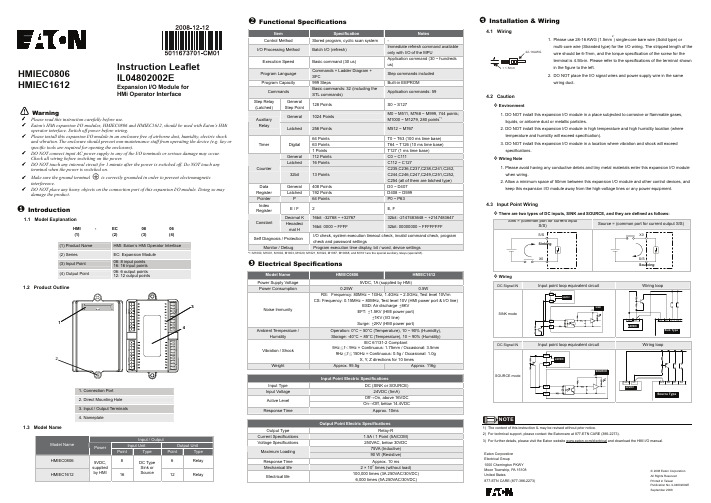
2. DO NOT place the I/O signal wires and power supply wire in the same wiring duct.
4.2 Caution Environment
1. DO NOT install this expansion I/O module in a place subjected to corrosive or flammable gases, liquids, or airborne dust or metallic particles.
ABB CP420人机界面(HMI)安装与操作手册说明书

CP420Installation and Operation Manual ABB, 1SBC159102M0201 2007-05EnglishCP420 Installation and Operation ManualForewordCP420 is a Human Machine Interface (HMI) with a 4.7" STN Liquid Crystal Display, and is water- and dust-resistant according to IP65/NEMA4.CP420 is CE-marked and meets your need to be highly transient-resistant while in operation.Also, its compact design makes connections with other machinery more flexible, thus achieving the optimal performance of your machines.CP400Soft is used to design applications of CP420; it is reliable, user-friendly and compatible with many models.Copyright © ABBAll rights reserved.Release: May 2007Document number: ABB, 1SBC159102M0201Please read the entire installation manual prior to installing and using this equipment.Only qualified personnel may install, operate or repair this equipment. ABB is not responsible for modified, altered or renovated equipment.Because the equipment has a wide range of applications, users must acquire the appropriate knowledge to use the equipment properly in their specific applications.Only parts and accessories manufactured according to specifications set by ABB may be used.ABB SHALL NOT BE LIABLE TO ANYONE FOR ANY DIRECT, INDIRECT, SPECIAL, INCIDEN-TAL OR CONSEQUENTIAL DAMAGES RESULTING FROM THE INSTALLATION, USE OR REPAIR OF THIS EQUIPMENT, WHETHER ARISING IN TORT, CONTRACT, OR OTHERWISE. BUYER'S SOLE REMEDY SHALL BE THE REPAIR, REPLACEMENT, OR REFUND OF PUR-CHASE PRICE, AND THE CHOICE OF THE APPLICABLE REMEDY SHALL BE AT THE SOLE DISCRETION OF ABB.Contents1Safety Precautions (5)2Installation (7)2.1Package Contents (7)3Product Specifications (8)3.1Description of Parts (9)3.2External and Cut-out Dimensions (10)3.3Mounting Procedure (10)3.4Grounding (11)3.5Power Supply and Wiring (12)4Dip Switches (13)5Communication Ports (14)6LCD Contrast Adjustment (15)7Operation (16)7.1Self Test (16)7.2System Menu (17)7.3Bench and Function T ests (18)7.4Setting Communication Parameters (18)7.5Downloading an Application (19)7.6Uploading an Application (20)7.7Copying an Application (22)7.8Passwords (23)1Safety PrecautionsBoth the installer and the owner and/or operator of the operator terminal must read and understand this installation manual.General–Only qualified personnel may install or operate the operator terminal.–The operator terminal must be installed according to the installation instruc-tions.–The operator terminal is designed for stationary installation on a plane surface, where the following conditions are fulfilled:• no high explosive risks• no strong magnetic fields• no direct sunlight• no large, sudden temperature changes–Never allow fluids, metal filings or wiring debris to enter any openings in the operator terminal. This may cause fire or electrical shock.–The operator terminal fulfills the requirements of article 4 of EMC directive 89/336/EEC.–Storing the operator terminal where the temperature is lower/higher than recommended in this manual can cause the LCD display liquid to congeal/ become isotopic.–The LCD display liquid contains a powerful irritant. In case of skin contact, wash immediately with plenty of water. In case of eye contact, hold the eye open, flush with plenty of water and get medical attention.–The supplier is not responsible for modified, altered or reconstructed equip-ment.–Use only parts and accessories manufactured according to specifications of the supplier.–Peripheral equipment must be appropriate for the application and location.–The figures in this manual serves an illustrative purpose. Because of the many variables associated with any particular installation, the supplier cannot as-sume responsibility for actual use based on the figures.–The supplier neither guarantees that the operator terminal is suitable for your particular application, nor assumes responsibility for your product design, in-stallation or operation.Power source–The operator terminal is equipped with a 24 V DC input. Supply power other than 24 V DC ± 15% will severely damage the operator terminal. Thus, check the power supply supporting the DC power regularly.Grounding–Without grounding, the operator terminal may be severely affected by excess noise. Make sure that the grounding is done properly from the power connec-tor at the rear side of the operator terminal. When power is connected, make sure that the wire is grounded.–Use a cable of at least 2 mm2 (AWG 14) to ground the operator terminal. Ground resistance must be less than 100 Ω (class3). Note that the ground cable must not be connected to the same ground point as the power circuit. Installation–Communication cables must be separated from power cables for operational circuits. Only use shielded cables to avoid unpredictable problems. During Use–Emergency stop and other safety functions may not be controlled from the operator terminal.–Do not use too much force or sharp objects when touching the keys, display etc.Service and Maintenance–Only qualified personnel should carry out repairs.–The agreed warranty applies.–Before carrying out any cleaning or maintenance operations, disconnect the equipment from the electrical supply.–Clean the display and surrounding front cover with a soft cloth and mild detergent.–Replacing the battery incorrectly may result in explosion. Only use batteries recommended by the supplier.Dismantling and Scrapping–The operator terminal or parts thereof shall be recycled according to local regulations.–The following components contain substances that might be hazardous to health and the environment: lithium battery, electrolytic capacitor and display.2Installation2.1Package ContentsThe following parts are found in the box:–Operator terminal CP420–4 installation fasteners–Power connector (connected to the 24 V DC power outlet)–This installation and operation manual (1SBC159102M0201)3Product SpecificationsParameter CP420Front panel, W x H x D170.3 x 102.6 x 4.2 mmMounting depth44.6 mmCut-out dimensions160.7 x 93.0 mmFront panel protection IP 65/NEMA 4Weight0.47 kgCOM19-pin female connector: RS232/RS485COM29-pin female connector: RS422/RS485Flash ROM 4 MBRAM512 KBCPU32-bit RISCBattery backed memory-Data/Recipe-Real time clock Yes (rechargeable Lithium battery)Display Mono STN LCD, 16 shades of blue, 240 x 128 pixels,CCFT backlight lifetime: approximately 50,000 h at 25 °CActive area of display, W x H 111 x 61 mm30 x 16 characters of 8 x 8 size can be displayedDisplay adjustment Via touch screen.T ouch screen AnalogPower supply24 V DC ± 15%. Less than 12 W.Operating temperature0 ° to +50 °CStorage temperature-10 ° to +60 °CAmbient humidity20 - 90% RH non-condensedVibration endurance0.5 mm displacement, 10-55 Hz, 2 hours per X-, Y- andZ-axis directionsShock endurance10 G, 11 ms 3 times in each direction of X-, Y- and Z-axes RF emissions CISPR 22, Class AElectrostatic Discharge IEC61000-4-2RF susceptibility IEC61000-4-3High frequency transients IEC61000-4-4Cooling Natural cooling3.1Description of Parts FrontBack3.2External and Cut-out Dimensions3.3Mounting Procedure1.Cut out the control front panel to match the dimensions (mm) below.2.Mount the operator terminal into the cut-out. Insert the fixtures to the holes on the unit and fasten the screws into the front panel. Do not tighten the screws with too much or uneven force, or it may cause the deformation of the operator terminal.3.The operator terminal is to be installed within the angle of 0 to 135 ° as shown below.3.4GroundingTo make sure that the operator terminal works properly and to prevent it fromradiating radio frequency noise, it must be connected to the earth ground.3.5Power Supply and WiringCP420 must use the power supply with 24 V DC and the power consumption is 12W .Perform the following steps to wire the power connector:1.Unplug the power connector and unscrew the screws.2.Strip approximately 1 cm of insulation. Insert the wire all the way into the power connector and then turn the screws tight.3.Plug in the connector to the power outlet of the operator terminal.Warning:T o avoid an electrical shock, be sure to switch off the power before connecting the communication/download cable to the operator terminal.Note:The power connector is already plugged into the power outlet of operator terminal when the package is first opened.4Dip SwitchesDip switchFunctionSW1Reserved SW2ReservedSW3 SW4Operation Mode ON ON Runs user application ON OFF Runs burn-in test program OFF ON Updates BIOSOFF OFFRuns bench test program SW5Communication ParametersONThe operator terminal uses the communication parameters defined on the operator terminal’s configuration screen for controller communication.OFF The operator terminal uses the communication parameters defined in CP400Soft for controller communication. SW6PasswordON The operator terminal asks the operator to enter a password after power-on self-test.OFF No password is required to start the operator terminal.SW7System MenuON The operator terminal displays the system menu.OFF The operator terminal runs user application without displaying the system menu. SW8Default User LevelON The default user level is set to 1 if the operator terminal requires no password to start its operation.OFF The default user level is set to 9 if the operator terminal requires no password to start its operation.SW9ReservedSW10COM2 PortFor RS485, this switch has to be set ON. For RS422, this switch has to be set OFF .ON OFF5Communication PortsCOM1, a 9-pin female connector, is used to connect the operator terminal to a controller via RS232 or RS485. Only COM1 can be used for download. COM2, a 9-pin female connector, is used to connect the operator terminal to a controller via RS422 or RS485.Note:Make sure that the connection is in accordance with the setting of the dip switches, for example COM2 RS485 corresponds to SW10 = ON. See section4 Dip Switches.Pin Function Pin Function1RS485+1RS422 TX+ (RS485+)2RS232 RXD2RS422 CTS+3RS232 TXD3RS422 CTS-4N/A4RS422 RX+5Signal ground5Signal ground6RS485-6RS422 TX- (RS485-)7RS232 RTS7RS422 RTS+8RS232 CTS8RS422 RTS-9Optional;+5V@100mA output 9RS422 RX-6LCD Contrast AdjustmentThe LCD contrast can be adjusted via the touch screen using the system menu command Set, and performing the following steps:1.Touch the upper-left and lower-right corners of the screen.2.Follow the route on the screen.3.Touch the square on the center of the screen to complete the task.See also section 7.2 System Menu.7Operation7.1Self TestOnce the operator terminal is turned on, it will automatically execute a self-test to check its hardware. The results of the self-test will be displayed on the screen according to the following picture.If any of tests does not pass the self-test, it will be noted with “Failed” next to the test item. Additionally, the message “Error! Press screen to continue” will be displayed at the bottom of the screen.If the power to the operator terminal or the PC was interrupted while download-ing, Firmware checksum or Application checksum will not pass the self-test, in-dicated by “Failed” in the self-test results after power is restored. If this happens, the user can simply follow the download procedure to re-download the applica-tion or data. After downloading again, all items should pass the self-test. Note:When using the operator terminal for the first time, remember to reset the real time clock (RTC).7.2System MenuSet the dip switch SW7 = ON. After the self-test, the system menu of the oper-ator terminal is displayed on the screen:The functions of the commands are briefly explained below:System menuFunctioncommandLink The operator terminal is connected.F2 - Confg Sets up the internal time clock and communication parameters in the operator terminal. All the settings has to made for theoperator terminal to work properly.Use , , and to move to desired field; + and - to setthe value of the field.F3 - Copy Copies application data to another CP420.F4 - Set Adjusts touch panel LCD contrast.See also section 6 LCD Contrast Adjustment.F5 - Run Runs the application.7.3Bench and Function TestsSet dip switches SW3 and SW4 = OFF to be able to run the bench and function tests for the CP420. T urn on the operator terminal to display the following screen:The bench test performs an overall hardware test, and the function test lets the user select which item to be tested.7.4Setting Communication ParametersThere are two ways to configure working parameters; to set parameters in the operator terminal or in CP400Soft.T o set parameters in the operator terminal, select Confg in the system menu.T o set parameters in CP400Soft, select Application/Workstation Setup . Select the Connection tab to set communication parameters.Note:The bench test will clear the application data of the operator terminal.Note:Remember to set dip switch SW5 = ON if parameters are set in the operator terminal.Note:Remember to set dip switch SW5 = OFF if parameters are set in CP400Soft.7.5Downloading an ApplicationConnect the RS232 port on the PC to the COM1 port on the CP420 using a TK401 cable. The connection can also be made according to the illustration be-low.Set the dip switch SW7 = ON . After the self-test, the system menu will be displayed on the screen and the operator terminal is ready to download the application.Start CP400Soft and open the application file to be downloaded. Make sure that the communication parameters are correctly configured. Also remember to compile the file before downloading it. The file has to be compiled every time a change has been made in the file before downloading it.9-pin male9-pin female RXD 2 2 RD TXD 3 3 SD GND 5 5 SG RTS 7 1 CD CTS 84 DTR 6 DSR 7 RTS 8 CTSNote:COM2 is mainly used for controller communication. When used for PC communica-tion, the pin setting described for COM2 in chapter 5 Communication Ports is used.Warning:T o avoid an electrical shock, be sure to switch off the power before connecting the download cable to the operator terminal.Then select Application/Download Firmware and Application in CP400Soft if it is a first time to download the application to the operator terminal; otherwise, select Application/Download Application . The following appears on the screen while the operator terminal is downloading:7.6Uploading an ApplicationAn application can also be uploaded from the operator terminal to the PC. Thus, a user can save an application as a *.V6F file in CP400Soft for future use.Make sure that the operator terminal and the PC are connected according to section 7.5 Downloading an Application . Set the dip switch SW7 = ON . After the self-test, the system menu will be displayed on the screen and the operator terminal is ready to upload the application.Also make sure that communication parameters are correctly configured. Select File/Upload Application in CP400Soft and the Save As dialog box will appear on the screen. Enter the name of a firmware file (*.AF6) to save. Click Save . Then the operator terminal will prompt for a password: enter the password set in CP400Soft from Application/Workstation Setup . Once the correct password is entered, the operator terminal starts to upload the application to the PC. For information about setting a password, please see section 7.8 Passwords .Warning:T o avoid an electrical shock, be sure to switch off the power before connecting the communication cable to the operator terminal.ABB, 1SBC159102M020121While the operator terminal is uploading, the following is displayed:After uploading, select File/Reconstruct Source in CP400Soft to display the Open dialog. Open the uploaded application file (*.C64 or *.AA6). The appli-cation screen will be displayed on the PC monitor. Finally, select File/Save As to save the application as a *.V6F file. Thus a source file can serve the purposes of maintenance and modification.Note:When uploading for the first time, make sure to first run the application once, or else the upload function will not work.22ABB, 1SBC159102M02017.7Copying an ApplicationT o copy an application from one CP420 to another CP420, select Copy from the system menu. Set the dip switch SW7 = ON and connect the two operator terminals with a download cable. After the self-test, the system menu will be dis-played on the screen.Select Copy in the system menu from the operator terminal with the application to be copied. The operator terminal will prompt for a password: enter the pass-word set in CP400Soft from Application/Workstation Setup . Once the correct password is entered, the CP420 starts to copy the application to the other CP420.For information about setting a password, please see section 7.8 Passwords .The following appears on the screens during the copying:Note:When copying for the first time, make sure to first run the application once, or else the copy function will not work.ABB, 1SBC159102M0201237.8PasswordsScenario 1: Requiring a password to start the operator terminal If the dip switch SW6 = ON , the user needs to enter a password to start the operator terminal. For this purpose, the designer can use the object Action Button in CP400Soft to create a button which displays the password table on the operator terminal display. A user with the right to access the table can register passwords and user levels in the table. In the illustration below, the button is an action button used to display thepassword table. When the button is selected the password table is displayed on the screen for a user with the right to access the table. Touch the password to highlight an area for entering a value.How to configure an Action Button is described in the CP400Soft User’s Manual.After registering passwords and user levels, set the dip switch SW6 = ON (i.e. password required). Restart the operator terminal and after the self-test the user will be prompted to enter a password in order to run the operator terminal. The operator terminal will determine the user level from the entered password. For instance, if the level of the password entered by the user is 2, then the operator terminal will set the user level to 2. User level 1 has the highest privilege and User level 9 has the lowest.Note:Only users of User Level 1 has the right of access to the password table.24ABB, 1SBC159102M0201Scenario 2: Re-entering a passwordThe object Action Button in CP400Soft also allows the designer to create a but-ton which asks the user to re-enter a password.For example, by pressing the button the password keypad will be displayed to prompt the user to enter a password. After entering the password, the opera-tor terminal will update the user level according to the most recent password which has been entered. Therefore, this button can be applied to raise or drop one’s privileges while the operator terminal is in operation.How to configure an Action Button is described in the CP400Soft User’s Manual.Scenario 3: Password-protecting a button in the operator terminal The designer can create a button which is protected by a password for execution. For example, a Goto Screen button can be designed with a high level of security; which means that a password with a high level of privilege is required in order to open the other screen. As the button is selected and the current user has a low-er privilege than has been set for the button, the operator terminal will prompt the user for a password. The user will need a password with at least the level of privilege that has been set for the button. This function can restrict users to ac-cess to certain parts of the application.Scenario 4: Requiring a password to copy or upload application When selecting F3 - Copy in the system menu or File/Upload Application in CP400Soft, the operator terminal will prompt for a password. The user will need to enter the correct password to copy an application from one CP420 to another. Note that setting this password is different from the passwords set in Scenarios 1-3. To set this password, select Application/Workstation Setup in CP400Soft. Under the Password tab, the designer is able to set the password.ABB FRANCEDivision Automation Products Export Department10 rue Ampère69685 ChassieuFranceT el. : +33 (0) 4 72 22 17 22 Fax. : +33 (0) 4 72 22 17 00ABB STOTZ-KONTAKT GmbH Po Box 10 16 8069006 HeidelbergGermanyT el. : +49 (0) 6221/701-1190 Fax. : +49 (0) 6221/701-1333www.abb.fr www.abb.de/stotz-kontakt。
MT6071 8071 8101iE Series HMI安装与启动指南说明书

Installation and Startup GuideThis document covers the installation of MT6071/8071/8101iE Series HMI, for the detailed specifications and operation, please refer to Brochure and EasyBuilder Pro User Manual. Install Environment:NEMA Rating The HMI product is NEMA 4 rated (Indoor Only).Electrical EnvironmentThe HMI product has been tested to conform to European CE requirements. This means that the circuitry is designed to resist the effects of electrical noise. This does not guarantee noise immunity in severe cases. Proper wire routing and grounding will insure proper operation.Environmental Considerations(1) Make sure that the displays are installed correctly and that the operatinglimits are followed. Avoid installing units in environments where severe mechanical vibration or shocks are present.(2)Do not operate the unit in areas subject to explosion hazards due toflammable gases, vapors or dusts. MT8071iE is certified in accordance with ATEX zone 2/22 categories 3 G/D. The unit has to be installed in an additional enclosure ensuring a minimal protection level for 3G/Dequipment. The enclosure equipped with the unit has to be certified and shouldn’t be opened when an explosive atmosphere is present. (3) Do not install the unit where acid gas, such as SO2 exists.(4) This device should be mounted in the vertical position and for use on the flatsurface enclosure.(5) Conform to UL508 (ISBN 0-7629-0404-6) machine safety for use inPollution Degree 2 Environment.Unpacking the UnitUnpack and check the delivery. If damage is found, notify the supplier.Installation InstructionsSecure the operator panel in position, using all the fastening holes and the provided bracketsand screws. Screw Torque: 2.6 ~ 3.9 lbf.in. (For reaching waterproof effect and preventing the panel from being deformed.)Type A(mm) B(mm) MT6071/8071iE192 138 MT8101iE260202USB Stick Clamp UsageCombining the USB Stick with the clamp and the tying strap can prevent USB stick from disconnecting with HMI when strong vibration is present.1. Insert the USB connector to the clamp and tie them together with the tying strap.2. Press the spring and insert the USB stick into HMI.Power ConnectionsMT6071/8071/8101iE seriesInstallation InstructionNOTE:Place the operator panel on a stable surface during installation. Dropping it or letting it fall may cause damage.NOTE:1. Conne ct positive DC line to the ‘+’ terminal and the DC ground to the ‘-’ terminal.2. When using a USB cable to download project file, please do not connect HMI with PLC and PC simultaneously to prevent potential difference from destroying USB ports of HMI and PC.(A)(B)Cutout3 4 (1)(2)(3)(5) (4) (6)(1) Installation Instruction, 2-sided A4 *1(2) Human Machine Interface *1(3) Power Connector *1(4) Brackets & Screws *1 pack (5) USB Stick Clamp & Tying Strap *1(6) Fuse 1.25A/250V 5*20mm *11 2System SettingsWhen HMI is powered up and displays image,click the system setting button.(Default System Password: 111111)It is necessary to connect the HMI toyour network through a RJ-45 cable.(N/A for MT6071iE)EasyBuilder Pro Software SettingsLaunch EasyBuilder Pro software, select yourproject file, press F7 shortcut key to openthe download dialog box:Select Ethernet > IP tab > Enter your HMI IP> Click Download to download this projectfile to HMI.If use MT6071iE, please select USB cable.( Please refer to EasyBuilder Pro User Manualfor software operation details )Communication ConnectionsCOM1 [RS232] 9 Pin, Male, D-sub COM2 / COM3 [RS485] 9 Pin, Female, D-subDIP SW Settings Limited WarrantyThis product is limited warranted against defects in design and manufacture.The proven defective product will either be repaired or replaced, at Weintek’s discretion.This warranty shall not cover any product which is(a) Out of warranty period which is 12 months from the manufacturing month of the HMI products.(b) Damage caused by Force Majeure, accident, negligence, improper installation or misuse.(c) Product has been repaired or taken apart by unauthorized technicians.(d) Products whose identification markings have been removed or damaged.PIN# COM1 [RS232]12 RxD3 TxD45 GND67 RTS8 CTS9PIN#COM2[RS485]2wCOM2[RS485]4wCOM3[RS485]1 Data- Rx-2 Data+ Rx+3 Tx-4 Tx+5 GND6 Data-789 Data+SW1 SW2 SW3 SW4 ModeON OFF OFF OFF Touch Screen Calibration ModeOFF ON OFF OFF Hide HMI System Setting BarOFF OFF ON OFF Boot Loader ModeOFF OFF OFF ON Not supportedOFF OFF OFF OFF Normalanywhere on the screen for more than 2 seconds when HMI starts.NOTE:COM2 and COM3 [RS485] 2W support MPI 187.5K, please use one at one time.Go to the Network tab, you may chooseto auto get DHCP IP, or designate yourown IP.678PowerThe unit can be powered by DC power only, voltage range: 24±20% Volts DC, compatible withmost controller DC systems. The power conditioning circuitry inside the unit is accomplished by aswitching power supply. The peak starting current can be as high as 2A.FusingRequire-mentsIf the display does not come on within 5 seconds of power up, remove power. An internal fuse willprevent damage if the polarity of the DC power is incorrect. Check wiring for proper connectionsand try to power up again.HighVoltageAn Internal fuse will prevent damage for overcurrent condition however it isn’t guaranteed. DCvoltage sources should provide proper isolation from main AC power and similar hazards.EmergencyStopA Hard-wired EMERGENCY STOP should be fitted in any system using HMI to comply with ICSSafety Recommendations.SupplyVoltageConditionDo not power the unit and inductive DC loads, or input circuitry to the controller, with the samepower supply. Note: The 24 VDC output from some controllers may not have enough current topower the unit.WireRoutinga. Power wire length should be minimized (Max: 500m shielded, 300m unshielded).b. Please use twisted pair cables for power wire and signal wire and conform to the impedancematching.c. If wiring is to be exposed to lightning or surges, use appropriate surge suppression devices.d. Keep AC, high energy, and rapidly switching DC power wiring separated from signal wires.e. Add a resistor and capacitor in the parallel connection between the ungrounded DC powersupply and the frame ground. This provides a path for static and high frequency dissipation.Typical values to use are 1M Ohm and 4700pF.CAUTIONNOTE: Make sure that all local and national electrical standards are met wheninstalling the unit. Contact your local authorities to determine which codes apply.HardwareConsiderationsThe system designer should be aware that devices in Controller systems could fail and therebycreate an unsafe condition. Furthermore, electrical interference in an operator interface can lead toequipment start-up, which could result in property damage and/or physical injury to the operator.If you use any programmable control systems that require an operator, be aware that this potentialsafety hazard exists and take appropriate precautions. Although the specific design steps depend onyour particular application, the following precautions generally apply to installation of solid-stateprogrammable control devices, and conform to the guidelines for installation of Controllersrecommended in NEMA ICS 3-304 Control Standards.ProgrammingConsiderationsTo conform with ICS Safety Recommendations, checks should be placed in the controller to ensurethat all writable registers that control critical parts of plant or machinery have limit checks built intothe program, with an out-of-limit safe shut down procedure to ensure safety of personnel.GME6871E0_MT6071_8071_8101iE1_Installation_160722DANGER5。
Pro-face GP4x01M系列5.7英寸和3.5英寸快速安装HMI操作特性说明书

EX-ED-Vxx-DVD
GP-Pro EX Development Software (download version + DVD backup media), xx refers to current version
PFXZGMAK1
1x Replacement Anti Rotation Tee, USB Cable Clamp (1 each Type A and Type mini-B, 1x 2mm spacer (panel thickness adjustment)
USB
1x USB 2.0 (Host) Type A with DC5V Power Supply
1x USB 2.0 (Host) Type mini-B
CF Card
not applicable
Powered by
Ro
General Specifications
Model Electrical
Specifications
Model
GP-4301TM
GP-4201TM
Order Numbers
PFXGM4301TAD
PFXGM4201TAD
Graphics Display Resolution 320 x 240 pixels (QVGA)
Display
Type
5.7” TFT Color LCD
PFXZGMNT1
Replacement display module installation nut (qty10)
PFXZGMSW1
Replacement Socket Wrench
PFXZGMCNDC1
Replacement DC Power connector (qty 5)
HMI 软件安装指导

3 Installing the hardware that I manually select from
a list (Advanced).
3
4
4 Network Adapters
5 Microsoft – Microsoft Loopback Adapter
5
Page 1 of 5
Start – Setting – Control Panel – Network Connection. Setting the virtual net card.
9 AlmList.exe
Alarm list
10 FigView.exe
Figure view
11 AlmAction.exe
Alarm action
12 PrtRpt.exe
To print history report
13 NTPDiag.exe
NTP diagnostics
14 EgdMonitor.exe ????
18 Save current setting
12 13
9
10
17 16
18
14 11
Page 4 of 5
Close MPC
Restart MPC
19 Click “Diagnostic” icon to popup the diagnostic map. Now there are 4 DPUs (1, 2, 16, 17) and 1 HMI (81) in the system.
5 TagList.exe
To list the global database
6 Trend.exe
To display a group of Trend
Wonderware Software 安装简介

Wonderware 软件包含如下几类:
Intouch 监控组态软件 SCADAlarm 报警组态软件 HMI Report 报表组态软件 Historian Server 历史库组态 Historian Client 历史数据查询客户端 Information Server Web浏览 授权简介
19
Wonderware授权简介
值得注意的是,虽然每个软件都需要硬件授 权,但是一台机器只能安装一个硬件授权; 这样就遇到一个问题,如果一台机器上同时 安装Intouch,HMI Report,这两套软件的授权 该如何处理呢?
Copyright © 2011 SGEPRI All Rights Reserved.
11
Historian 软件简介
Historian :为历史数据库组态软件,通过导入 的方式,将Intouch组态的数据库直接导入 Historian内,支持的点数依据购买授权的点数 限制,例如授权为1000点,该软件只能导入 1000点的用于存入历史数据库(一个开关量 为一个点,一个模拟量也算是一个点)。在组 态Intouch的数据库时,根据需要选择是否要 入历史数据库,避免超过授权的限制。
14
Historian Server 软件安装
安装步骤: 3.安装完毕即可显示,目前显示红色的内容表 示授权未安装或者安装不正确。
Copyright © 2011 SGEPRI All Rights Reserved.
15
Historian Client 软件安装
Historian Client为客户端软件,用于查询 Historian Server存储的数据,是区别于HMI Report软件查询的另一种查询方式。可以显 示曲线,某一测点数据,查询速度快,曲线方 式查询直观。该软件的安装无需特殊设置,按 照默认方式安装即可。如果没有授权,该软件 可以以“演示模式” 运行15分钟。
SINUMERIK 810D 840D HMI Advanced SW 06.03.14 升级说

SINUMERIK 810D / 840D27/03/2003Upgrade InstructionsHMI Advanced V06.03.14________________________________________________________________________________Upgrade Instructions for SINUMERIK 810D / 840D HMI Advanced SW 06.03.14 6FC5253-6BX10-3AG_________________________________________________________________________________Installation on PCU 50 / 70 :To install this software, you will need a PCU 50 / 70 with pre-installed operating system WinNT4.0 V06.02.01 or higher, or operating system WinXP V07.03.02.01 or higher.If WinNT4.0 V06.01.xx is installed as the operating system on your PCU 50, you must first upgrade it with service pack 06.02.01 to V06.02.01.The HMI Advanced software version 06.03.14 includes the HMI basic software version 06.03.14.HMI Advanced also includes all texts in the five standard European languages. The help for setting and machine data is generally only available in German and English.Please refer to the document "Installation and Start-Up HMI Advanced (IM4)" !Please note the supplementary conditions applicable to HMI Advanced software version 6.3.General information about installing the HMI Advanced software:Any previous version of the HMI software will be detected. This will then be updatedwithout loss of any data in the data management system.All files stored in directories F:\USER, F:\ADD_ON, F:\OEM will be left unchanged. It is therefore importantto make any changes to .INI files in these directories rather than in F:\MMC2 or F:\HMI_ADV.Important: After you have installed HMI Advanced, boot your machine as requested by InstallShield. Allow HMI Advanced to ramp up and then boot again. HMI Advanced version 6.3.14 will then be ready to operate.Important: After you have installed HMI Advanced 6.3, you will not be able to downgrade to HMI Advanced 6.1 or 6.2 again, even if you deinstall HMI Advanced 6.3 beforehand. If you wish to downgrade to an earlier version, you will need to use an existing ghost image.Please note that the HMI Advanced software includes the standard cycles V06.03.10.However, these are no longer automatically copied to the Standard Cycles directory on the hard disk, but are available as archives in the Archives / Cycle Archives directory. This directory also contains upgrade instructions for standard cycles in file SIEMENSD.ARC or SIEMENSE.ARC (which can be read under Services with the editor).INSTALLATION GUIDE for HMI Advanced software version 06.03.14:1.) Installing software from a CD-ROM using a parallel cable1.1) Standard procedure for PCs with Win95/98 and FAT161.2) Procedure for PCs with Win95/98 and FAT322.) Installing software from a CD-ROM to the PCU 50 via a network3.) New features as compared to SW 6.24.) Compatibility5.) Debugging log6.) Tips and tricks====================================================================© Siemens AG, 2003A&D MC RD 5Page 1 of 61.1) Installing software from a CD-ROM using a parallel cableStandard procedure with INTERSVR on PC / PG with FAT16====================================================================To install the software you will need the shipped CD-ROM containing the system software.INTERSVR / INTERLNK is used to transfer the software to the PCU 50 / MMC 103. This can bedone under DOS / Win3.11 / Win95 / Win98 only on condition that the PG / PC has ahard disk partition with FAT16 file structure (not FAT32 !).SWITCH OFF THE CONTROL SYSTEM !Use the parallel transmission cable (PC-Link cable, LapLink cable) to connect theparallel port LPT on the PG / PC to LPT1 on the PCU 50 / 70.Copy directory HMI_Advanced from the CD to drive C:\ on the hard disk of your PG/PCand rename it "MMC102". If there is insufficient space available on drive C:,you can use any other local hard disk drive.The software cannot be installed directly from the CD(but see procedure for FAT32)! If it is not already installed, copy INTERSVR.EXE from theCD to C:\<Windows directory>\COMMAND and run INTERSVR <drive with MMC102>,for example, INTERSVR C:Now start the PCU 50 / 70 and, while it is ramping up, select the service menu with <cursor down>,<input> when the message "Please select the operating system to start:" is displayed.Then select1 Install/Update SINUMERIK Systemand, after you have entered the password,2 Install via Serial/Parallel Line.The HMI Advanced software will now be transferred to the PCU. You will then be requested to reboot the PCU. After the system ramp-up in WinNT, the software will be installed automatically guided by INSTALLSHIELD. You can navigate through the prompt boxes of InstallShield using the TAB, cursor keys andInput and activate the button "New Installation" with the space bar.When you reboot the PCU 50 / 70, the system ramps up with HMI Advanced software version 06.03.14.Exit PC/PG server mode by pressing Alt + F4.====================================================================1.2) SOFTWARE UPGRADE from a CD-ROM using a parallel cableProcedure with INTERLNK on PC / PG with FAT32====================================================================You must use this procedure if the PC you are using has only partitions with aFAT32 file structure.To install the software you will need the supplied CD-ROM containing the system software.Copy the INTERLNK.EXE from the CD to <Windows directory>\COMMANDon the PC. Enter the following line in CONFIG.SYS:device=c:\windows\command\interlnk.exe /AUTOUse the parallel transmission cable (PC-Link cable, LapLink cable) to connect theparallel port LPT on the PG / PC to LPT1 on the PCU 50 / 70.Now start the PCU 50 / 70 and, while it is ramping up, select the service menu with <cursor down>,<input> when the message "Please select the operating system to start:" is displayed.Then select8 Start PC LinkWhen you input the password and confirm, INTERSVR is started and waits for a connection to the PC.This is established by booting the PC. It will then be possible to access the partitions onthe PCU hard disk from the PC.Now copy the entire contents of the HMI_Advanced directory on the CD todirectory D:\INSTALL on the PCU.Once the software has been transferred, exit INTERSVR on the PCU by pressing Alt + F4.After you have booted the PCU in WinNT / WinXP, the software is automatically installed guided by INSTALLSHIELD. You can navigate through the prompt boxes of InstallShield using the TAB, cursor keys and Input and activate the button "New Installation" with the space bar.When you reboot the PCU, the system runs up with HMI Advanced software version 06.03.14.====================================================================2.) SOFTWARE UPGRADE from a CD-ROM to the PCU 50 / 70 via a network====================================================================This method of installation can be used only if the PCU 50 / 70 is already linked to a network which allows data to be transferred directly to the PCU 50 / 70 hard disk.You can set up this connection based on the NetBEUI protocol (as well as TCP/IP withservice menu 2.4 or later) in the DOS service menu on the PCU 50 / 70 by selecting menu option1 Install/Update SINUMERIK SystemThe new software is then copied to D:\INSTALL on the PCU 50 / 70 as described in 1.2, and then installed automatically.Or:The network connection is made on the WinNT / XP desktop and the software installeddirectly when you run SETUP.EXE from the CD supplied.====================================================================3.) New features as compared to HMI Advanced 6.2====================================================================System:• Compatible with Windows NT 4.0 SP6 (as previously) and Windows XP Pro SP1• Area menu expanded to 32 softkeys• PC-Anywhere integrated• Hardkeys (of OP010x) are supported• User-specific, configurable operating structure (e.g. "Maintenance" area")• Technology cycles (standard cycles) supplied in a new form• Optional: New colors and softkey form for operator interface (with Windows XP only)Machine area:• Program control: Configurable "Programmed stop 2"• Expansion for ISO-H functionsParameters area:• Display screen for ELG parametersTool management:• Direct selection with more than one magazine• Expansion for ISO-H functions• Inch / metric selection for tool catalog and tool cabinet• Language dependency for location types and loading pointsProgram area:• Contour editor: Grinding allowances• Editor: Undo / redo for files on hard disk• Improvements in accessing network drivesServices area:• Operator interface for copy / paste adjusted to match Program area• Access to network drives• Support for "loadable compile cycles"Diagnosis area:• Drive diagnostics with "traffic lights" symbol• Version display for cyclesStart-up area:• Support for PROFIBUS drives (840Di only)• Service screens for NC memory allocationOperator interface expansions:• Function for shifting bits• Functions for string processingTechnology cycles• The HMI Advanced software version 06.03.14 includes the technology cycles (standard cycles) version06.03.10.====================================================================4.) Compatibility====================================================================• The HMI Advanced software version 06.03.14 can be combined with the 840D NCU software versions 5.3 and 6.x and with CCU3 software version 6.x. CCU1 / 2 is no longer supported.• Simulation is based on NCU software version 6.3.17 (48.02). Problems with simulation may therefore be encountered if a later SW version is installed on the real NCU.• The help system is based on the documentation for NCU / CCU software version 6.4.• The NC alarm texts are based on NCU / CCU3 software version 6.4.• AUTOTURN 5.2 is compatible.• STEP7 for SINUMERK hardware versions V5.1 and V5.2 (currently only with WinXP as PCU operating system) can be installed and executed under HMI Advanced.• The "Emergency Boot Disks" V2.4.x will be needed for WinXP-based systems.• OEM: 16-bit applications are no longer supported or executable.Note:As a result of expanded functions, more communication resources in the connected NCU(s) / CCU3(s) will be utilized when these are operated in conjunction with HMI Advanced. NC alarm 5000 will be generated if there are insufficient communication resources available. You can set the available communication resources with NC machine data 10134 MM_NUM_MMC_UNITS. The default setting 6 will ensure sufficient resources when one PCU with HMI Advanced is operated on one NCU / CCU3. NC machine data 10134 must be set to "8" for 2 PCUs with HMI Advanced operating on one NCU. When additional software is operated in combination with HMI Advanced, it may also be necessary to increase the setting of NC MD 10134 to avoid activating alarm 5000.====================================================================5.) Debugging log (SW 06.03.14 vis-à-vis SW 06.02.17)====================================================================ERLde48432 TOOLMAN: Incorrect help text in the tool managementERLde49134 Problem with PDF and HLP files.ERLde52840 OEM: MMCControls - enabled does not work properlyERLde53254 TOOLMAN: User authorization for TC_DPH.ERLde54337 Scratching: With flat D numbers and inactive WO ...ERLde53254 Machine: Distance to go in wrong axis with SZSERLde55610 Services: Even active GUD are overwrittenERLde48521 IB, File fct: VSK menu wrong after comparison fileERLde49315 Diagnosis/Service Axis "Unit" column not translated.ERLde49842 Parameters: Wrong DP number in tool displayCHMdc07685 The list of rotatable tool types does not include type 580ERLde50206 LS problems with SKs which include text, but have no functionERLde50208 TOOLMAN: Tool type 210 boring bar display and input fieldsERLde50879 Editor: Horizontal scrolling active when not selectedERLde51853 Editor: String ";wizard" acts as block identifierERLde52153 Wizard: EXITLS does not workMGLdm00448 NC series start-up with status progr. cannot be read inERLde54609 TOOLMAN: Unloading from spindle to tool cabinet ...ERLde56407 TOOLMAN: Input screen for cutting edge data in standard ...ERLde57054 Servo trace: Physical address values cannot be enteredCHMdc08036 SU: Formatting error on loading machine dataBRKdb07920 SU: Generation of a comparison file / machine data editorERLde54010 Header: JOG INC display disappears when channels are switchedERLde54695 Installation: In cst.dir\hlp.dir *.txt and *.pdf type DOSERLde55215 Workpiece selection: Superfluous message with TOA data in WPDERLde55680 IB, File fct: "DH signaling parameter error" for comparison dataERLde55780 Variable view: $AA_SYNA_MEM should be called $AC_SYNA_MEM====================================================================6.) Tips and tricks====================================================================Contour calculator:The orientation of the coordinate system in the contour calculator is always set with display MD9650 CMM_POS_COORDINATE_SYSTEM, e.g. = 8 for technology ”Turning”. MD9610 CTM_POS... has no meaning.Cycles support from software version 4.4:The "old" cycles support function from version 4.4 is available on the ETC menu in theeditor if directory User Cycles contains file . Itcan be copied from standard cycles if necessary.Editing large files:The ASCII editor in HMI Advanced can edit files of 16MB maximum per default. It is possibleto increase the maximum file size to 56MB by changing the settingMemFactor= in file AEDITOR.INI.Protection levels for softkeys in the Machine, Diagnosis and Start-Up areas:The protection levels for functions in the Diagnosis and Start-Up areas accessed viasoftkeys can be set individually in files DG.INI and IB.INI, section [AccessLevel],(software version 5.1 and later).Simulation:The simulation technology setting (turning / milling) can be changed in displayMD 9020 TECHNOLOGY= (1: Turning, <>1: Milling).Note: When you change this MD, delete DPWP.INI as well !Full keyboard, key combinations:Key combinations such as Alt+Ctrl+Del, Alt+Tab, Alt+F4, ... are disabled. If you need themfor OEM or servicing purposes, you can modify entry SeqAct= in section [MMC103keyb] in fileE:\WINNT.40\SYSTEM.INI or E:\Windows\SYSTEM.INI accordingly.Operation with PC keyboard: Hardkey functions are assigned to the keys in the Num block when NumLock is deactivated.NC series start-up: Skipping "general NCK reset":With NCK 4.3 and later, file IBN.SYF contains an entry (command) for performing a general NCK resetprior to a series start-up. If this command is used when machine data 11210 UPLOAD_MD_CHANGES_ONLY is set while the SIB archive is being generated, it may not be possible to read in the archive later ondue to inconsistencies in its content. This means that the archive has to be read in again. Should this unusual error occur, there is, of course, no point in executing a general NCK reset each time. For this reason, the following setting has been provided for this contingency:New entry in file DINO.INI:...; options for data in/out (archives), questions and priority of COM-interfaces[Function]...; 1: ask before overwriting CFG_RESET.INI, 0: don't askAsk_for_CFG_RESET.INI=0...In the case of a series start-up with INI entry Ask_for_CFG_RESET.INI=1, the following promptis displayed in response to _NC_ACT\CFG_RESET.INI: "The selected file already exists!Overwrite?". This gives you the option of skipping this file and a general NCK reset (with softkey NO).。
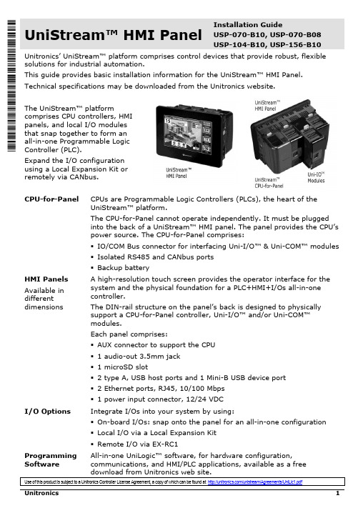
Unitronics UniStream HMI 面板安装指南说明书
UniStream™ HMI Panel Installation GuideUSP-070-B10, USP-070-B08USP-104-B10, USP-156-B10 Unitronics’ UniStream™ platform comprises control devices that provide robust, flexible solutions for industrial automation.This guide provides basic installation information for the UniStream™ HMI Panel. Technical specifications may be downloaded from the Unitronics website.The UniStream™ platformcomprises CPU controllers, HMIpanels, and local I/O modulesthat snap together to form anall-in-one Programmable LogicController (PLC).Expand the I/O configurationusing a Local Expansion Kit orremotely via CANbus.CPU-for-Panel CPUs are Programmable Logic Controllers (PLCs), the heart of theUniStream™ platform.The CPU-for-Panel cannot operate independently. It must be pluggedinto the back of a UniStream™ HMI panel. The panel provides the CPU’spower source. The CPU-for-Panel comprises:▪IO/COM Bus connector for interfacing Uni-I/O™ & Uni-COM™ modules▪Isolated RS485 and CANbus ports▪Backup batteryHMI Panels Available indifferent dimensions A high-resolution touch screen provides the operator interface for the system and the physical foundation for a PLC+HMI+I/Os all-in-one controller.The DIN-rail structure on the panel’s back is designed to physically support a CPU-for-Panel controller, Uni-I/O™ and/or Uni-COM™modules.Each panel comprises:▪AUX connector to support the CPU▪1 audio-out 3.5mm jack▪1 microSD slot▪2 type A, USB host ports and 1 Mini-B USB device port▪2 Ethernet ports, RJ45, 10/100 Mbps▪1 power input connector, 12/24 VDCI/O Options Integrate I/Os into your system by using:▪On-board I/Os: snap onto the panel for an all-in-one configuration▪Local I/O via a Local Expansion Kit▪Remote I/O via EX-RC1Programming Software All-in-one UniLogic™ software, for hardware configuration, communications, and HMI/PLC applications, available as a freeHMI Panel Installation GuideBefore You BeginAlert Symbols and General RestrictionsWhen any of the following symbols appear, read the associated information carefully. Symbol Meaning DescriptionDanger The identified danger causes physical and property damage.Warning The identified danger could cause physical and property damage. Caution Caution Use caution.▪All examples and diagrams are intended to aid understanding, and do not guarantee operation. Unitronics accepts no responsibility for actual use of this product based on these examples.▪Please dispose of this product according to local and national standards and regulations. ▪This product should be installed only by qualified personnel.▪Failure to comply with appropriate safety guidelines can cause severe injury orproperty damage.▪Do not attempt to use this device with parameters that exceed permissible levels.▪Do not connect/disconnect the device when power is on.Environmental Considerations▪Ventilation: 10mm (0.4”) of space is required between the device top/bottom edges and the enclosure’s walls.▪Do not install in areas with: excessive or conductive dust, corrosive or flammablegas, moisture or rain, excessive heat, regular impact shocks or excessive vibration, in accordance with the standards and limitations given in the product’s technicalspecification sheet.▪Do not place in water or let water leak onto the unit.▪Do not allow debris to fall inside the unit during installation.▪Install at maximum distance from high-voltage cables and power equipment. Caution▪The UniStream™ HMI Panel is designed to comply with NEMA 4X, IP66 and IP65.Note however that the Audio Protection Seal must remain plugged in for NEMA4X and IP66, in which case the audio sound level from the internal speaker issignificantly reduced.UniStream™Kit Contents▪ 1 HMI Panel: 7”, 10.4” or 15.6”7” panel, includes 4 mounting brackets10.4” panel, includes 8 mountingbrackets and 2 panel supports15.6” panel, includes 10 mounting brackets and 2 panel supports▪ 1 panel mounting seal ▪ 1 programming cable ▪ 1 power terminal blockHMI Panel DiagramHMI Panel Front and Rear ViewCaution ▪ Keep the seal in place when the embedded speaker is not used. The seal mustHMI Panel Installation GuideInstallation Space ConsiderationsAllocate space for:▪The HMI Panel including the CPU and any modules that will be installed on it ▪Opening the doors of the CPU and modulesFor exact dimensions, please refer to the Mechanical Dimensions shown below. HMI Panel Mechanical Dimensions7” PanelUniStream™10.4” Panel15.6” PanelHMI Panel Installation GuidePanel MountingN OTE▪Mounting panel thickness must be less or equal to 5mm (0.2”).▪Ensure that the space considerations are met.1. Prepare a panel cut-out according to the dimensions of your model, USP-070-B10,USP-104-B10, or USP-156-B10 as shown in the previous section.2. Slide the panel into the cut-out,ensuring that the Panel Mounting Seal isin place as shown on the right.3. Push the mounting brackets into theirslots on the sides of the panel as shownbelow.4. Tighten the bracket screws against thepanel. Hold the brackets securelyagainst the unit while tightening thescrews.When properly mounted, the panel issquarely situated in the panel cut-out asshown below.USP-070-B10: 4 mounting brackets USP-104-B10: 8 mounting bracketsUSP-156-B10: 10 mounting bracketsUniStream™Wiring▪This equipment is designed to operate only at SELV/PELV/Class 2/Limited Powerenvironments.▪All power supplies in the system must include double insulation. Power supplyoutputs must be rated as SELV/PELV/Class 2/Limited Power.▪Do not connect either the ‘Neutral’or ‘Line’ signal of the 110/220VAC to device’s 0V point.▪Do not touch live wires.▪All wiring activities should be performed while power is OFF.▪Use over-current protection, such as a fuse or circuit breaker, to avoid excessivecurrents into the HMI Panel supply port.▪Unused points should not be connected (unless otherwise specified). Ignoring thisdirective may damage the device.▪Double-check all wiring before turning on the power supply.Caution ▪To avoid damaging the wire, use a maximum torque of 0.5 N·m (5 kgf·cm).▪Do not use tin, solder, or any substance on stripped wire that might cause thewire strand to break.▪Install at maximum distance from high-voltage cables and power equipment.Wiring ProcedureUse crimp terminals for wiring; use 26-12 AWG wire (0.13 mm2–3.31 mm2).1. Strip the wire to a length of 7±0.5mm (0.250–0.300 inches).2. Unscrew the terminal to its widest position before inserting a wire.3. Insert the wire completely into the terminal to ensure a proper connection.4. Tighten enough to keep the wire from pulling free.Wiring GuidelinesIn order to ensure that the device will operate properly and to avoid electromagnetic interference:▪Use a metal cabinet. Make sure the cabinet and its doors are properly earthed.▪Use wires that are properly sized for the load.▪Individually connect each 0V point in the system to the power supply 0V terminal.▪Individually connect each functional ground point () to the earth of the system (preferably to the metal cabinet chassis).Use the shortest and thickest wires possible: less than 1m (3.3’) in length, minimum thickness 14 AWG (2 mm2).▪Connect the power supply 0V to the earth of the system.N OTE For detailed information, refer to the document System Wiring Guidelines, located in the Technical Library in the Unitronics’ website.HMI Panel Installation GuideWiring the Power SupplyThe UniStream™ HMI Panel device requires an external 12/24VDC power supply.▪In the event of voltage fluctuations or non-conformity to voltage power supplyspecifications, connect the device to a regulated power supply.Connect the +V and 0V terminals as shownin the accompanying figure.HMI Panel Interface ConnectionsUse the following:Ethernet CAT-5e shielded cable with RJ45 connectorUSB Device Use the proprietary programming cable supplied with the deviceUSB Host Standard USB cable with Type-A plugmicroSD Standard microSDAudio Out 3.5mm stereo audio plug with shielded audio cableInstalling CPU-for-Panel, Uni-I/O™ & Uni-COM™ ModulesRefer to the Installation Guides provided with these modules.▪Turn off system power before connecting or disconnecting any modules or devices.▪Use proper precautions to prevent Electro-Static Discharge (ESD).Removing the Panel1. Disconnect the power supply.2. Remove all wiring and disconnect any installed devices according to the device’sinstallation guide.3. Unscrew and remove the mounting brackets, taking care to support the panel toprevent it from falling during this procedure.。