GH-EP-05运作控制程序
COP-05设备控制程序B0

“办公/辅助设备一览表”(ASA-ADFM-42)
使用部门设备及(或)工序《作业指导书》
设备与固定资产管理课《人力资源控制程序》(CEOP-04)
“领料单”(ASA-WRFM-03)
使用部门“设备日常维修记录表”(ASA-ADFM-44)
“设备年度维修周期计划表”(ASA-ADFM-45)
“设备维修保养记录表”(ASA-ADFM-46)
“设备异常联络单”(ASA-ADFM-47)
使用部门“设备日常维修记录表”(ASA-ADFM-44)
技术支援部门“设备维修保养记录表”(ASA-ADFM-46)
设备与固定资产管理课“设备异常联络单”(ASA-ADFM-47)
使用部门
权限审批人“设备报废申请”(ASA-ADFM-49)
设备与固定资产管理课
设备领取/使用
设备维护
异常处理
报废。
深圳仁天芯科技有限公司 GH 系列铝电氧电容器说明书

PREPARED BY CHECKED BY APPROVED BYSPECIFICATIONDescription: Aluminum Electrolytic Capacitors AISHI P/N: Part of GH Series SERIES: GH ITEM: Customer P/N: No.: CRS-JD-1711132APPROVED BYPlease Return One Copy with Your Approval承认后请寄回一份湖南艾华集团股份有限公司HUNAN AIHUA GROUP CO., L TDTel: (0737)6184466 Fax : (0737)6180493版本更改原因更改内容生效日期CRS-JD-1711132 新建新建 2017-11-11Customer 深圳市仁天芯科技有限公司SERIES GH DATE2017-11-11FIG-1TABLE-1No. CustomerPart No.AishiPart No.Capacitance(μF)Toleranceon RatedCapacitance(%)RatedV oltage(Vdc)SurgeV oltage(Vdc)OperatingTemp. Range(℃)tanδ(120Hz)(Max)LeakageCurrent(μA)(2min.)Max RippleCurrent (mArms)at105℃100kHzEnduranceat 105℃(Hours)Dimensions (mm)AppearanceDrawing No.ΦD Lαd F1 EGH1HM4R7D11OT4.7 ±205063-40~+105 0.14 3 35 5000 51120.5 2.0 FIG-12 EGH1HM100D11OT10 ±205063-40~+1050.145 50 500051120.5 2.0FIG-15 产品特性PRODUCT CHARACTERISTICS5.1电气特性ELECTRICAL CHARACTERISTICS序号 No. 项目 Item 测试方法 Test method性能 Performance5.1.1额定工作电压 Rated voltage电压:直流电压值+交流电压峰值≤额定电压 . Voltage :DC. Voltage + peak ripple voltage ≤ Rated voltage6.3V .DC~100V .DC5.1.2电容量 Capacitance测试频率:120Hz (±20%) 测试电路:串联等效测试电压:0.5Vrms 以下+1.5~ 2.0VDC Measuring frequency: 120Hz ±20% Measuring circuit:Series equivalent circuit Measuring voltage:0.5Vrms or less +1.5 to 2.0 VDC容量偏差:-20%~+20% Capacitance tolerance: -20%~+20%5.1.3 损失角正切值 Dissipation factor测试条件与5.1.2电容量测试相同 Testing conditions are the same as 5.1.2 for capacitanceDF 不大于规定值 DF: Not more than the specified value.5.1.4 漏电流 Leakage current在电容器两端施加额定工作电压,并串联1000±100Ω电阻,在施加电压2分钟后,测量漏电流。
QP-05设备控制程序

设备控制程序制订部门:生产部编制日期: 2017年04月01日生效日期: 2017年04月01日制订:审核:审批:1.目的:对生产设备进行维护保养和有效管理,以保持其能力和性能,以达到预期的使用效果。
2.适用范围:适用于为满足生产需要的所有设备的使用、维护和保养。
3.定义:无4.职责:4.1 行政部负责设备编号、登记、标识,制定重要设备操作指导书并确定维护保养项目。
4.2 设备操作者对设备按保养项目进行日常保养,并按时作好记录。
4.3 生产部设备技术员负责对设备的操作者进行维护、操作方面的指导、培训工作,负责维修和确定送外修,并作好记录。
4.4 采购部对设备试用及生产过程中的异常现象联络供应商处理,并按使用部门之申请采购设备及零配件。
5.作业程序5.1 相关部门根据实际生产需要提出设备请购申请,经批准购买之设备,生产部应在投入使用前进行试用、检测等验收工作,如不合格,采购部应及时通知供应商处理。
5. 2 新设备使用前,生产部技术维修员应核对设备资料,编号方法如下:5.2.1设备PRE -XXX;PR表示生产部E (生产设备代码);PRE-001XXX - 顺序号(四位码001~999)行政部: ADE-0015. 3行政部&生产部对公司设备进行统一编号,《设备操作指导书》按设备说明书进行编写,并建立建立《设备清单》当有需要改善时生产部部技术维修员修订相关《设备操作指导书》。
5.4新《设备操作指导书》和修订后的《设备操作指导书》品管部文控文员按《文件控制程序》管理和分发。
5.5设备保养5.5.1生产现场所使用的设备和生产部技术员根据实际的编制每年一度《年度设备保养计划表》,5.5.2一级保养:由使用单位应对设备按要求进行日常维护和保养,包括清洁卫生,尤其接触产品的地方一定要保持的非常干净。
并将维护和保养结果记录于《设备日常点检表》中,生产部设备管理人员对设备进行其监督与管理。
5.5.3二级保养:由使用单位班组长主管每月维护和保养,并将维护和保养结果记录于《设备日常点检表》中生产部设备管理人员对设备进行其监督与管理。
HCS5五轴机械手控制系统说明书V3.120140412(V3.1配V1.9IO板)

HC-S5机械手控制系统操作手册V3.1版本河北神州自动化设备科技有限公司目录1 系统配置及安装 (1)1.1 基本配置 (1)1.2 系统的安装 (1)2 操作面板 (2)2.1 外观及说明 (2)2.2 主画面及轴定义 (3)2.2.1 主画面说明 (3)2.2.2 机械手轴定义 (3)3 运行模式 (4)3.1 原点复归 (4)3.2 手动操作 (4)3.2.1 轴的手动操作 (5)3.2.2 夹具的手动操作 (6)3.2.3 吸盘的手动操作 (7)3.2.3 辅助设备的手动操作 (8)3.2.4 预留动作的手动操作 (9)3.3自动运行 (10)3.3.1 自动运行数据的监视 (10)3.3.2 自动运行时参数的修改 (11)3.3.3 单步运行 (11)3.3.4 单循环运行 (11)3.3.4 自动运行时速度的调节 (11)4 程序的管理 (12)4.1 程序载入和创建 (12)4.2 程序教导 (13)4.2.1 轴动作的教导 (14)4.2.2 程序起始点的教导 (15)4.2.3 堆叠的教导 (16)4.2.4 吸盘/夹具的教导 (17)4.2.5 注塑机信号的教导 (19)4.2.6 辅助设备的教导 (20)4.2.7 预留的教导 (21)4.2.8 等待信号的教导 (22)4.2.9 序列动作的教导 (23)4.2.10 条件的教导 (24)4.2.11 程序参数的修改 (25)4.3 程序快速设定 (26)4.4 教导选择 (30)4.5 教导程序举例 (32)4.5.1 程序要求 (32)4.5.2 程序过程 (32)4.5.3 教导程序 (32)5 功能设定 (33)5.1 信号检测 (34)5.2 产品设定 (36)5.3 运行参数 (37)5.4 安全点设定 (38)5.5 产品堆叠 (44)5.6 系统设定 (46)5.6.1系统设定 (47)5.6.2权限管理 (48)5.6.3 备份/还原 (49)5.6.4 机械参数 (50)5.7 机器参数 (51)5.7.1 机器结构 (51)5.7.2 机器时间 (54)5.8 维护 (55)6 I/O监视与报警记录 (56)6.1 I/O监视 (56)6.2 报警记录 (57)6.3 报警信息及报警原因 (58)7 电路板端口定义 (62)7.1 主控制板端口定义 (62)7.2 I/O板的端口定义 (63)7.3 伺服驱动接口定义 (64)8 接线图 (65)8.1主控制板与I/O板的接线图 (65)8.2 操作面板与主控制板的接线图 (66)8.3 伺服连线及参数设定 (67)8.3.1松下伺服电机使用范例 (67)8.3.2三菱伺服电机使用范例 (68)8.4 机械手与注塑机的连接 (69)9 电路板安装尺寸图 (71)9.1 主控板安装尺寸 (71)9.2 I/O板安装尺寸 (72)1 系统配置及安装1.1 基本配置1、8寸真彩触摸屏2、五轴伺服控制板3、I/O板4、电源部分(2个电源供应器)5、通讯线1.2 系统的安装1、配线作业必须由专业电工进行。
GHP使用说明书
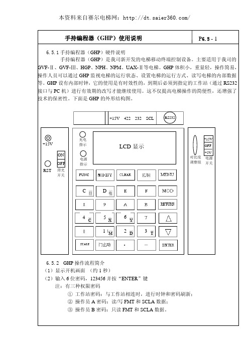
进行十进制、十六进制以及二进制之间的切换,用于数据读写。 (5)“MENU”――菜单键
作为备用按钮。 (6)“MODE”――快捷键
快捷进入需要的菜单,见“菜单和快捷键”。 (7)“RETURN”――返回键
① 返回上一级菜单; ② 刚启动 GHP 手持编程器时,会进入上一次操作的电梯工号的界面,按“ENTER”键
6.5.4 按键功能说明 (1)“FUNC”――功能键
作为备用按钮。 (2)“MODIFY”――修改键
用于各种数据的修改。 (3)“CLEAR”――清除键
① 快捷键,清除“专用运行”、“门止动功能”、“呼叫保持”、“层高测定”、 “WD110%取消”、“SDS 试验”等,例如:MOD 15 CLEAR。
专用运行
门止动
数据读写
呼叫保持
取消设置 主微机读写 SCLA 数据读写 主微机位显示 SCLA 数据位显示 规格表修改
三级菜单
设置 取消 设置 取消 设置 取消
四级菜单
快捷键(*注释 A)
MOD+0+确认 MOD+1+确认
备注
MOD+27+确认 MOD+40+确认 MOD+4+确认 MOD+5+确认 MOD+6+确认 MOD+7+确认 MOD+15+确认 MOD+15+CLR
轻载上行 轻载下行 重载上行 重载下行 零点设置 满载点设置
前 1 次故障 前 2 次故障 前 3 次故障 前 4 次故障 前 5 次故障 前 6 次故障 前 7 次故障 前 8 次故障 前 9 次故障
┆ ┆ 前 30 次故障 前 31 次故障 故障 1-8 故障 9-16 故障 17-24 故障 25-32
高迪亚水冷螺杆控制说明书

50%负载阀断开, 75%负载阀接通
延时 75-100%切换时间
75%负载阀断开 1#压机 进入 100%负载
间隔温控周期
控制系统说明书
延时 Y-U切换时间
Y 接触器断开 U接触器接通 延时 25%-50%切换时间 25%负载阀断开,50%负载阀接通 延时 50-75%切换时间
50%负载阀断开, 75%负载阀接通
进入温控
进入温控
3
② 关机 表二
步序
1 2 3 4 5 6
制冷
关机信号 25%负载阀打开 延时 压缩机、阀关机 延时 延时水泵关机、25%负载阀断电
控制系统说明书
2、控制功能 压缩机防频繁起停: (1)压缩机再次启动间隔时间:如:“180 秒”即压缩机停机时间不小于 180 秒。 (2)压缩机最少运转时间:如:“300 秒”即压缩机开机后至少运行 300 秒,此时温控失 效(故障保护,手动关机除外)。 压缩机均衡运行: 在运行过程中,防止某台压机一直连续运行,特设有“压机均衡原理”,即累计运行时 间短的压缩机先启动,累计时间长的压缩机先关闭。
Omega EP510, IP510, EP511, IP511 电磁泵控制器用户指南说明书

e-mail:**************For latest product manuals: Shop online at User’sGuideEP510, IP510, EP511, IP511 SERIES ELECTROPNEUMATIC CONVERTERSThe information contained in this document is believed to be correct, but OMEGA accepts no liability for any errors it contains, and reserves the right to alter specifications without notice.Servicing North America:U.S.A.Omega Engineering, Inc.Headquarters:Toll-Free: 1-800-826-6342 (USA & Canada only)Customer Service: 1-800-622-2378 (USA & Canada only) Engineering Service: 1-800-872-9436 (USA & Canada only) Tel: (203) 359-1660 Fax: (203) 359-7700 e-mail:**************For Other Locations Visit /worldwide***********************California Proposition 65WARNING: Cancer and Reproductive Harm !AIR CONNECTIONSSUPPLYConnect air supply to 1/4 NPT port marked "IN." If the above specifications are not met, possibility of internal clogging exists. Also see MAINTENANCE section.OUTPUTConnect output to 1/4 NPT port marked "OUT.”GAUGEThe plugged 1/8 NPT port in the base of the transducer is internally connected with the "OUT" port. A pressure gauge can be attached to this port to monitor output pressure.WARNINGIn order to get optimal service from this transducer and ensure warranty coverage the following MUST be followed:ŸThe supply air quality to this instrument must be instrument quality air as defined by ISA Standard 57.0.01-1996.1. Dew point not higher than 35˚F.2. No particulates larger than 3 microns in size.3. Maximum oil content of 1 ppm.ŸNo mechanical adjustments or calibrations are necessary or allowed. All calibration MUST be done with electrical potentiometers on the enclosed circuit board only. See “CALIBRATION” section of instructions for more information.3M4109/0719 IP510, EP510, IP511, EP511 SERIESA 4MOUNTINGGENERALNEMA 1 and NEMA 4X transducers can be mounted in any position.DIRECT MOUNTING PIPEŸAny NEMA 1 transducers may be supported by its own plumbing for air supply and output. NEMA 4X transducers may also be supported using 1/2" explosion proof conduit in the electrical port.PANELŸNEMA 1 transducers may be mounted to a panel with two No. 10-32 screws using threaded holes in the back of a transducer or with two to four No. 8-32 screws using threaded holes in the bottom of a transducer.ŸNEMA 4X transducers may be mounted to a panel with three No. 10-32 screws using threaded holes in the back of a transducer or with four No. 8-32 screws using threaded holes in the bottom of a transducer. In the case of back-mounting, if the panel extends towards the screw-on cover, a 3/16-inch-thick spacer MUST be used between the back of the transducer and the panel in order for the panel to clear the transducer's screw-on cover.EP510 AND IP510WE I V E D I S W E I V T N O RF WE I V P O T BOTTOM VIEW Drawings and dimensions are for reference only.5DIRECTIONS 1.Remove the cover (see WARNING above).2. Bring wiring to the terminal block, located on the circuit board, through 1/2 NPT electrical conduit connection. 18 A.W.G. is recommended; 14 A.W.G. is the maximum wire size. Connect wires to the terminal block per TABLE 2. Care must be exercised to prevent damage to delicate internal parts when inserting wiring through the 1/2” NPT conduit opening.3. An internal grounding screw is provided on all units to facilitate separate ground when required. An external grounding lug is also provided on NEMA 4X enclosures.4.Reinstall the cover tightly using all o-rings and locking devices to insure compliance with Agency Approvals.ELECTRICAL CONNECTIONSPRECAUTIONS TO BE OBSERVED DURING INSTALLATIONThe Transducers were tested at the EMC Test Centre, Dunfermline, Fife, KY11 5LB to the Electromagnetic Compatibility Directive effective January 1, 1996. The relevant EMC specifications tested were the following: EN 50081-1 (1992) and EN 50082-1 (1992). A Technical Construction File, Serial #107 was written and Certificate of Conformity issued by a Competent Body.EN 50081-1 (1992): Test results confirmed that no precautions need to be observed during installation regarding electro-magnetic emissions from the IP510A Transducers.EN 50082-1 (1992): The following precautions should be taken during installation to maintain the advertised accuracy specifications for the Transducers. The input wiring to the transducer should be isolated from other high voltage transient wiring. The momentary switching on and off of nearby relays, motors, or other high capacitive or inductive loads can have a minor effect on the terminal based linearity specification (1.0% of span, standard range models). Any change in output pressure is minimal and momentary, and is considered to be within its performance capabilities. Use of a ferrite bead collar on the input wires entering the transducer is recommended shouldinstallation next to high electromagnetic interference be necessary.WARNING1.Remove the cover to gain access to the “SPAN”, (marked S), “FINE ZERO”, (marked Z) and the “DAMPING”, (3/4 turn low profile ) potentiometers. The unmarked pot “COURSE ZERO”, is used only for major calibration range changes. This adjustment should only be attempted by factory trained personnel. For NEMA 1 enclosure, just slide open the access door on the top of the cover.2.Set electrical input signal to 0% (e.g. 4 mA or 0 VDC ).3. FORWARD ACTING UNITS: Using "FINE ZERO" potentiometer, adjust output pressure to 0% output (e.g. 3 psi).4.Set electrical input signal to 100% (e.g. 20 mA or 10 VDC).5. FORWARD ACTING UNITS: Using "SPAN" potentiometer, adjust output pressure to 100% output (e.g. 15 psi).6. Repeat steps 2 through 5 until output pressures are properly set.NOTE: Under certain circumstances, output pressure may exhibit cycling action. To eliminate this condition, use the “DAMPING”potentiometer.7. Reinstall cover using original screws and gaskets, if equipped.MAINTENANCEWhen used properly, these transducers should provide more than one million cycles without failure. If a situation should occur in which the transducer's behavior is abnormal, the cause is usually related to a pneumatic problem.ELECTRICAL MAINTENANCEAn electrical problem must be isolated by a skilled technician. The power source and all wiring should be checked first. Circuit board failures are very rare, and can be confirmed by the following method. Loosen the screws, or posts that hold the circuit board in place. Unplug the blue connector from the circuit board, and insert two small pieces of wire into the connector.IMPORTANT: Connect a current source with the polarity as follows. Positive to the (RED) coil wire and Negative to the (BROWN) coil wire of 10 mA to the connector, which powers the yellow coil. With supply pressure on, the unit should produce an output pressure equivalent to 80% or more of the maximum output pressure. If there is little or no output, then the unit is clogged. Should it produce an adequate output pressure, then the circuit board is the primary suspect. The unit must be returned to the factory for repair. PNEUMATIC MAINTENANCEAll 510 and 511 Series transducers also have an internal orifice filter, but if contaminates do invade the transducer, they can clog the internal orifice and block the flow, or jam open the internal supply valve. The problem can be corrected through replacement of the orifice (see TABLE 5: KITS) or by cleaning the internal supply valve, or both.6REPLACING ORIFICE:This can be accomplished without removing the unit from its mounting or plumbing.1. Turn off supply pressure and unscrew the brass orifice assembly located on the side of the housing with the gauge port. NOTE: Small sealing o-ring may remain inside of the housing. If it does, remove it with a paper clip or some other small probe. The replacement assembly will contain this o-ring.2. Install the new orifice assembly making sure the o-ring is seated on the end of the screw.CLEANING INTERNAL SUPPLY VALVE:1. Turn off the supply pressure.2. Use a 9/16" socket or wrench to unscrew the brass plug in the bottom of the transducer.NOTE: Take care not to lose the supply valve spring which is retained by the bottom plug.3. Clean out any dirt or debris and reassemble, making sure the stem of the supply valve is nested in the supply valve spring.AGENCY APPROVALS, SPECIAL NOTES, AND CAUTIONSINTRINSIC SAFETYAll 510 and 511 Series transducers are rated intrinsically safe by both FM and CSA for:CLASS I, DIVISION 1, GROUPS A,B,C,D HAZARDOUS LOCATIONS.Proper FM-approved intrinsically-safe wiring requires external FACTORY MUTUAL RESEARCH CORPORATION ENTITY-APPROVED SINGLE-CHANNEL barriers to be selected, based upon MAXIMUM ENTITY PARAMETERS of 510 and 511 Series transducers:ENTITY PARAMETERS:Vmax = 28 V, Imax = 150 mA, Ci = 0.22uF, Li = 0 mH.Voc and Isc of a barrier shall not exceed Vmax and Imax of the transducer.(Li + Lwiring) and (Ci + Cwiring) shall not exceed La and Ca of a barrier.NOTICE: For proper FM and CSA approved intrinsically-safe wiring, request Drawing Number 990-439-000 from the Factory.NONINCENDIVEAll 510 and 511 Series transducers are approved as NONINCENDIVE by FM and approved as suitable by CSA for: CLASS I, DIVISION 2, GROUP A, B, C, D HAZARDOUS LOCATIONS.A barrier is not necessary when these transducers are in these locations.ENCLOSURESCompliance with NEMA 4X and CSA ENC4 enclosure ratings require that the screw-on cover has the O-ring installed. In case of a need for replacement parts, see TABLE 3.78EXPLOSION & DUST-IGNITION PROOF CERTIFICATIONS FACTORY MUTUAL and CANADIAN STANDARDS ASSOCIATIONEXPLOSION PROOF FOR CLASS I, DIV 1, GROUP B, C, D.DUST-IGNITION PROOF FOR CLASS II, DIV 1, GROUP E, F, G.SUITABLE FOR CLASS III LOCATIONS.EP511 AND IP51110Where Do I Find Everything I Need for Process Measurement and Control?OMEGA…Of Course!Shop online at TEMPERATUREThermocouple, RTD & Thermistor Probes, Connectors, Panels & AssembliesWire: Thermocouple, RTD & ThermistorCalibrators & Ice Point ReferencesRecorders, Controllers & Process MonitorsInfrared PyrometersPRESSURE, STRAIN AND FORCETransducers & Strain GagesLoad Cells & Pressure GagesDisplacement TransducersInstrumentation & AccessoriesFLOW/LEVELRotameters, Gas Mass Flowmeters & Flow ComputersAir Velocity IndicatorsTurbine/Paddlewheel SystemsTotalizers & Batch ControllerspH/CONDUCTIVITYpH Electrodes, Testers & AccessoriesBenchtop/Laboratory MetersControllers, Calibrators, Simulators & PumpsIndustrial pH & Conductivity EquipmentDATA ACQUISITIONCommunications-Based Acquisition SystemsData Logging SystemsWireless Sensors, Transmitters, & ReceiversSignal ConditionersData Acquisition SoftwareHEATERSHeating CableCartridge & Strip HeatersImmersion & Band HeatersFlexible HeatersLaboratory HeatersENVIRONMENTALMONITORING AND CONTROLMetering & Control InstrumentationRefractometersPumps & TubingAir, Soil & Water MonitorsIndustrial Water & Wastewater TreatmentpH, Conductivity & Dissolved Oxygen InstrumentsM4109/0719OMEGA’s policy is to make running changes, not model changes, whenever an improvement is possible. This affords our customers the latest in technology and engineering.OMEGA is a registered trademark of OMEGA ENGINEERING, INC.© Copyright 2017 OMEGA ENGINEERING, INC. All rights reserved. This document may not be copied, photocopied, reproduced, translated, or reduced to any electronic medium or machine-readable form, in whole or in part, without the prior written consent of OMEGA ENGINEERING, INC.FOR WARRANTY RETURNS, please have thefollowing information available BEFORE contactingOMEGA:1. P urchase Order number under which the productwas PURCHASED,2. M odel and serial number of the product underwarranty, and3. Repair instructions and/or specific problemsrelative to the product.FOR NON-WARRANTY REPAIRS, consult OMEGA for current repair charges. Have the following information available BEFORE contacting OMEGA:1. Purchase Order number to cover the COST of the repair,2. Model and serial number of the product, and 3. Repair instructions and/or specific problems relative to the product.RETURN REQUESTS/INQUIRIESWARRANTY/DISCLAIMEROMEGA ENGINEERING, INC. warrants this unit to be free of defects in materials and workmanship for a period of 13 months from date of purchase. OMEGA's WARRANTY adds an additional one (1) month grace period to the normal one (1) year product warranty to cover handling and shipping time. This ensures that OMEGA's customers receive maximum coverage on each product.If the unit malfunctions, it must be returned to the factory for evaluation. OMEGA's Customer Service Department will issue an Authorized Return (AR) number immediately upon phone or written request. Upon examination by OMEGA, if the unit is found to be defective, it will be repaired or replaced at no charge. OMEGA's WARRANTY does not apply to defects resulting from any action of the purchaser, including but not limited to mishandling, improper interfacing, operation outside of design limits, improper repair, or unauthorized modification. This WARRANTY is VOID if the unit shows evidence of having been tampered with or shows evidence of having been damaged as a result of excessive corrosion; or current, heat, moisture or vibration; improper specification; misapplication; misuse or other operating conditions outside of OMEGA's control. Components in which wear is not warranted, include but are not limited to contact points, fuses, and triacs.OMEGA is pleased to offer suggestions on the use of its various products. However, OMEGA neither assumes responsibility for any omissions or errors nor assumes liability for any damages that result from the use of its products in accordance with information provided by OMEGA, either verbal or written. OMEGA warrants only that the parts manufactured by the company will be as specified and free of defects. OMEGA MAKES NO OTHER WARRANTIES OR REPRESENTATIONS OF ANY KIND WHATSOEVER, EXPRESSED OR IMPLIED, EXCEPT THAT OF TITLE, AND ALL IMPLIED WARRANTIES INCLUDING ANY WARRANTY OF MERCHANTABILITY AND FITNESS FOR A PARTICULAR PURPOSE ARE HEREBY DISCLAIMED. LIMITATION OF LIABILITY: The remedies of purchaser set forth herein are exclusive, and the total liability of OMEGA with respect to this order, whether based on contract, warranty, negligence, indemnification, strict liability or otherwise, shall not exceed the purchase price of the component upon which liability is based. In no event shall OMEGA be liable for consequential, incidental or special damages.CONDITIONS: Equipment sold by OMEGA is not intended to be used, nor shall it be used: (1) as a “Basic Component” under 10 CFR 21 (NRC), used in or with any nuclear installation or activity; or (2) in medical applications or used on humans. Should any Product(s) be used in or with any nuclear installation or activity, medical application, used on humans, or misused in any way, OMEGA assumes no responsibility as set forth in our basic WARRANTY/DISCLAIMER language, and, additionally, purchaser will indemnify OMEGA and hold OMEGA harmless from any liability or damage whatsoever arising out of the use of the Product(s) in such a manner.Direct all warranty and repair requests/inquiries to the OMEGA Customer Service Department. BEFORE RETURNING ANY PRODUCT(S) TO OMEGA, PURCHASER MUST OBTAIN AN AUTHORIZED RETURN (AR) NUMBER FROM OMEGA'S CUSTOMER SERVICE DEPARTMENT (IN ORDER TO AVOID PROCESSING DELAYS). The assigned AR number should then be marked on the outside of the return package and on any correspondence.The purchaser is responsible for shipping charges, freight, insurance and proper packaging to prevent breakage in transit.。
DH-QP-005生产过程控制程序A0

4.9.1制程异常时,若无立即有效之对策时,须先停线并要求相关部门协助解决,参照《纠正预防措施控制程序》。
4.9.2制程中产生之不合格品参照《不合格品控制程序》。
4.10样品管理:测试或检验中使用之比对样品每次使用后要放回品质部样品柜保管。
4.11作业环境管理:若有温湿度管制区域依要求条件每日记录于温湿度记录表中,部门主管需签字确认,IPQC不定期作抽查。
4.1.2.1特殊过程的控制
4.1.2.1.1浸錫、波峰焊、回流焊、烙铁焊为生产工艺的特殊过程。
4.1.2.1.2要在作业指导书上注明特殊过程的工艺参数和工艺要求。
4.1.2.1.3生产部要对錫炉、回流炉的溫度作管制,并登录于《温度测试记录表》及《锡炉使用记录》,生产主管需签字确认,IPQC不定期作检查。特殊过程岗位的员工需培训上岗。
4.13.2品质确认后,判定产品品质符合规格标准,而且仪器失效部份不影响产品品质者,为确保产品品质,则当日所生产出来的在制品,以合格仪器予以重新检测。
4.13.3品质确认后,判定产品不合于规格标准,而且仪器失效部份会影响产品品质者,除当日生产出来的产品应予以召回外,并且品质须对已入库的产品,以批为基准往前推算进行复检确认,直至连续两批入库品均为合格产品为止。
4.6领料须依生产订单开出《原材料领料单》,如需退料则开《退料单》,成品出库须打印《送货单》。
4.7《流程标识卡》管理在制品。
4.7.1操作员须填写《流程标识卡》。
4.7.2作业中流程标识卡须紧附产品。
4.7.3流程标识卡上之记录须与实际作业状态符合。
4.8生产设备与治具管理参照《设备管理控制程序》执行。
3.3工艺部:负责制作工艺文件、设备管理及协助解决生产异常与工艺改善。
- 1、下载文档前请自行甄别文档内容的完整性,平台不提供额外的编辑、内容补充、找答案等附加服务。
- 2、"仅部分预览"的文档,不可在线预览部分如存在完整性等问题,可反馈申请退款(可完整预览的文档不适用该条件!)。
- 3、如文档侵犯您的权益,请联系客服反馈,我们会尽快为您处理(人工客服工作时间:9:00-18:30)。
5.1.4各部门按规定地点分类放置废弃物,由行政部统一进行处理,具体详见《固体废弃物控制程序》:
1〕对可直接回收利用的废弃物,如废纸箱、废金属等,由物料部组织出售。
2〕对不可直接回收利用的废弃物,如废机油、废油布、废电池、废灯管、废电线电缆等,由行政部安排分类处置。
6.2《新项目环境影响控制程序》
6.3《应急准备和响应控制程序》
6.4《对相关方环境施加影响控制程序》
6.5《化学品控制程序》
6.6《固体废弃物控制程序》
6.7《能资源控制程序》
6.8《废气排放控制程序》
6.9《过程控制及过程中检验控制程序》
6.10《基础设施/设备管理控制程序》
7.0相关表单
7.1《环境控制点清单》
7.2《每月能源用量统计表》
5.1.5制造部门、行政部负责对本公司的水、电、油类等能源进行规划管理,增设必要的能源计量仪表,每月统计用量,对主要耗能设备进行重点管理,以确保能源充分有效的利用,降低单产的能耗,具体详见《能资源控制程序》。
5.1.6各部门严格依据以上程序和标准的要求,开展环境管理工作,并做好相应记录。当出现不符合情况,参照《纠正与预防措施控制程序》处理,行政部负责随时检查各部门的执行情况。
4.1工程人员在工艺转化阶段应考虑如何减少产品对环境的影响,并纳入工艺要求。
4.2设备管理人员负责生产部负责化学物品的管理。
4.5行政部负责能源的规划管理。
4.6行政部负责废弃物的分类处置。
4.7行政部负责设置环境控制点,检查各部门环境管理的执行情况。
5.2对新上工程、工程技术改造等新项目的环境管理详见《新项目环境影响控制程序》。
5.3对于所提供的产品或服务中涉及重要环境因素的供货商,本公司依据《对相关方环境施加影响控制程序》对其施加影响,使他们的行为符合程序和有关要求。
5.4对紧急情况的处理详见《应急准备和响应控制程序》。
6.0相关文件
6.1《纠正与预防措施控制程序》
文件修订记录
版次
修订内容
修订日期
修订者
A0
ISO 14001:2004版新订文件
2007-12-27
1.0目的
对与本公司的重要环境因素有关的运行与活动进行有效控制,确保其符合环境方针、目标与指针的要求,以实现环境行为的不断改进。
2.0适用范围
适用于本公司环境管理体系运行过程的控制。
3.0定义
无。
4.0权责
5.1.2制造部门严格按照相应工艺规程和作业指导书的要求进行生产;各班组和设备管理人员参照《过程控制及过程中检验控制程序》和《基础设施/设备管理控制程序》的要求对生产设备进行维护保养;品管部负责对检测设备进行维护保养。本公司对可能造成重大环境影响的设备采取相应措施进行管理,如对噪声采取隔音、吸音等措施防止厂界噪声超标;对于漏、滴油现象采用托盘予以收集等。
5.0工作程序
5.1本公司在日常的环境管理中,对与重要环境因素相对应的运行与活动进行重点控制,对其中可能造成重大环境影响的作业点,由行政部将其设置为环境控制点,列入《环境控制点清单》,明确控制的要求。
5.1.1工程人员在工艺转化过程中应考虑防止环境污染、节约资源与能源等有关问题,新产品在保证质量的前提下,向长寿命、高效率、多功能、可再生利用、小型轻量化发展;在工艺转化阶段,需对原材料的使用或生产工艺可能引起的污染等环境影响进行评审;提倡采用无害化的工艺技术,并简化制造工艺,提倡使用无毒害(ROHS)的材料并减少其用量;物料部需统计每种产品的物耗,从计划、采购、工艺、包装、贮存、运输等方面考虑,给出建议逐步削减其用量。