恒温伴热器说明书(第二版)
恒温火器产品说明书

564 TV GSR2 35K Gas Fireplace -D istributorNOTE: FAN & GS2 WIRELESS WALL MOUNT REMOTE PRE-INSTALLED STEP #2 - ADD AN OPTIONAL FIREBACKNotable ExtrasCommon Brick/HerringboneHandmade BrickFPX Old World Stucco564 TV GSR2 35K Gas Fireplac e - DistributorSTEP #4 - ADD YOUR VENTINGPower Vent Exhaust KitIncludes 3.9" pipe, 90° elbow,high wind horizontal cap.Minimum Vent Section,Rear Vent Flue AdapterVertrical Termination onlyMinimum Horiz Vent Kit E, 8"Includes 90 deg elbow, 3.9" pipe, 12" pipe, (2) 6" pipe, high wind horiz. CapNOTE: ADDITIONAL PIPE SECTIONS MAY BE NEEDED TO MEET THE REQUIREMENTS FOR A SPECIFIC APPLIANCE. REFER TO THE 36" CoolSmart TV Wall™ Kit564 TV 35K Clean Face GSR2 Gas Fireplac e - DistributorNOTE: FAN & GS2 WIRELESS WALL MOUNT REMOTE PRE-INSTALLEDREQUIRED FORPROPANE CONVERSION!STEP #1 - SELECT A LOG SETSTEP #2 - ADD AN OPTIONAL FIREBACKNotable ExtrasCommon Brick/HerringboneHandmade Brick FPX Old World Stucco564 TV 35K Clean Face GSR2 Gas Fireplac e - DistributorSTEP #4 - VENTINGPower Vent Exhaust KitIncludes 3.9" pipe, 90° elbow,high wind horizontal cap.Minimum Vent Kit H, 36" CoolSmart TV Wall™ KitNOTE: ADDITIONAL PIPE SECTIONS MAY BE NEEDED TO MEET THE REQUIREMENTS FOR A SPECIFIC APPLIANCE. REFER TO THE Vent Section,Rear Vent Minimum Horiz Vent Kit E, 8"Includes 90 deg elbow, 3.9" pipe, 12" pipe, (2) 6" pipe, high wind horiz. CapFlue AdapterVertrical Termination only。
恒温电子恒温器手册说明书

Fan coil units3PictogrammesManual cool/heat changeoverAutomatic cool/heat changeover based on water temperatureAutomatic cool/heat changeover based on air temperatureControl of the 3-way/4-port ON/OFF valve. The water valve shut-off once the desired temperature is reached.The controller controls the electric heater as integration or replacement of the hot water heating system. When the operating mode selector witch is turned on “electric heater” and the electric heater is turned on, the fan runs continuously at medium speed.The fan speed can be set at one of the 3 speeds (low, medium or maximun) by turning the operation mode selector.The fan speed is switched automatically based on the difference between the temperature set on the thermostat and the room temperature.Optimised comfort cooling. When the fan coil has reached the desired setpoint, the fan will operate at medium speed and at regular intervals to ensure constant room temperature and lower sound.The controller prevents the fan coil unit from operating in one mode, if the required water temperature is not achieved to operate in the selected mode.The dead zone is a temperature interval close to the set temperature. When the air is warmer/cooler than the top/lower limit of the neutral zone, the cooling/ heating mode is selected.FWV FWL FWM01234567891011kWFWD24681012141618202224kWFWB24681012141618202224kWFan Coil Reference 2-pipe4-pipeProduct portfolioFan Coil Reference 2-pipe4-pipeCooling HeatingFan Coil Reference 2-pipe4-pipeDaikin fan coil units deliver quiet, reliable, controllable comfort of air conditioning without all the noise of other central systems.Fan coil units are a highly efficient means of turning a water chiller or hot water boiler into an efficient, quiet air conditioning system.The units are super quiet because the only moving part is the fan; making them ideal for use in offices, hotels and the home.The new range of fan coil units offers 5 models, of which 3 in flexible application. A wide range of accessories is available.For the ultimate in quiet, controllable air conditioning with all the comfort but none of the bulk or noise, the clear choice is Daikin.Easy to installFast and easy field set up, ready for use!KEY HOLE SYSTEM / LEVELLING•Quick fixing system for wall/ceiling mounting Advantage : No need to unscrew the nut •Units just need to be perfectly leveledAdvantage : No need to calculate the condensate drainageWATER CONNECTION •Pre-assembled 3-way/4-port ON/OFF valves are available •Valve packages are insulated, no extra drain pan required •Valve packages contain balancing valves and sensor pocket •Valve packages can be factory-mounted and are leak tested•Same valve package can be installed vertically and horizontally, on the right or on the left side of the unit without changeAdvantage : Easy to connect even when space is limitedCONDENSATE DRAINAGE•Condensate drain pan features slopes to reduce water accumulation •Supplied with flexible rubber hose pipe for easy connectionAdvantage : Eliminates the need to align drain pan outlet with customer pipingAdvantage : No need for collar if pipe diameter is compatibleQUICK ELECTRICAL CONNECTIONS•Fast-on connections for electrical options : no tools needed •Controls are already factory-wired and testedAdvantage : Control panel no longer needs to be opened (external customer connections)•Wiring diagram on the cover of the electrical boxEasy to maintainLow maintenance and high effeciency QUICK REMOVAL OF WASHABLE FILTER•No tools needed•Same system on vertical and horizontal unitsAdvantage: very fast filter removalELECTRIC HEATER RESETTING•No relay up to 2kW capacityAdvantage: even quieter operation•Manual reset easily accessible•Equipped with two overheat cut-out thermostats(manual & automatic reset)Advantage: anticipates the upcoming standardsFAN MOTOR/CONTROL PANEL ACCESSIBILITY• 4 screws to access to the fan motor•Fan board is removable without bringing the unit down•Motor is life-lubricated and has a life span of 40,000 hours•Control panel removable by a single screw•Can be unfolded for a better component access•Removable grilles•Easy access to control valvesSTRUCTURE•Modular concept•Height of the units only 240mm for all the sizes•Cooling coil and fan module is made of:-galvanised sheet steel-internally insulated (with 3mm close-cell polyurethane)•Key-hole system for fast mounting•Rubber anti-vibration damper to isolate the unit from supporting structure •Straight duct connector is mounted to both suction and discharge side (width 30mm)• A template is available in the carton box for easy connection to the ceiling HEAT EXCHANGER•3, 4 or 6 stage row cooling coil•Standard left handed water connections + air-purge(water connections can easily be turned)•Drain pan can to collect the condensate from:-Heat exchanger-Regulating valvesFAN MOTOR ASSEMBLY•1, 2 or 3 centrifugal fans with forward profile blades, dynamically andstatically balanced•7-speed electrical motors (with thermal protection on windings)•All 7 speeds pre-wired in the factory in the terminal block of the switch box •To reduce the requested installation space is the terminal block located onthe same side as the water connectionsAIR FILTER•Located in the air inlet•Removable from the bottom•Made of acrylic fiber, filter class EU2STRUCTURE•Possibility of installation both in horizontal and vertical position•Reduced height 280mm up to model 10•The unit is made of:- galvanised sheet steel- insulated with noise-proof/anti-condensing material(self-extinguishing in Class 1, with a thickness of 10mm)•Key-hole system for fast mounting•Straight duct connector is mounted to discharge side(width 30mm)HEAT EXCHANGER• 1 or 2 stage row cooling coil•Standard left handed water connections + air-purge•System for collecting and discharging condensate setup either for ceiling or wall mounting.FAN MOTOR ASSEMBLY•Dual intake centrifugal fans made of aluminum, dynamically and statically balanced •3-speed electric motor, installed on vibration damping supports(with thermal protection on windings)AIR FILTER•Air-intake module + Filter is standard delivered with each unit•Removable filter from the bottom•Made of acrylic fiber, filter class EU2EPIMSA6EPIA6FWV/L/M FWB FWD01y02y y03y y04y y y05y06y yx /v07y 08yx /v x /v09x /v 10yx /v x /v12v 16v 18vy v /x vEasy to control !The new fan coil units can be operated by 3 different controllers:• electronic control built-in (ECFWEB6)• electronic control remote (ECFWER6)• electromechanical control built-in (ECFWMB6)The electronic control consists of:•Operating mode selector , to turn the fan coil on and off,to choose the type of operating mode (automatic or at fixed speed) and to control the electric heating.•Cooling / Heating selector•Operational LEDs that indicates the current operation mode•Thermostat to control the room temperature•Free contacts for external enabling signal that may switch on or off the unit.• Free contacts for centralized cool/heat changeover • Water temperature probe • Air temperature probeSeveral configurations are possible by changing dip switches.The electromechanical controller includes a fan speed selector (3 speeds + stop) and manual cool/heat changeover. In case of the on/off valves, control can also be done through this controller.Power interface / master slave interfaceAn additional interface is required for units with a current greater than 1,12A.Master slave interface (EPIMSA6: 4x3A)For remote control of up to 4 fan coil units, an optional master/slave interface can be installed. Up to 3 EPIMSA6can be connected in parallel (--> max. 12 fan coils).Power interface (EPIA6: 1x16A)This is absolutely required for connection of ECFWER6 to FWD12 to18. It can be used as an alternative for EPIMSA6for all other fan coils.Master slave interface is only needed in case of remote control of multiple fan coil unitsObigation to use master slave interface or power interface Obligation to use power interfaceControl featuresBasic control functionsOptionsCooling/heating changeover2-p i p e4-p i p eCOOLINGTotal capacity (H)kW Sensible capacity (H)kW Water flow l/h Pressure drop kPa HEATINGHeating capacity (H)kW Water flow l/h Pressure drop kPa Power input HW Coil water volume lAir flowH/M/L m 3/h Sound power level H/M/L dBA WeightFWV kg FWM kg FWL kg COOLINGTotal capacity (H)kW Sensible capacity (H)kW Water flow l/h Pressure drop kPa Cooling coil water volume l HEATINGHeating capacity (H)kW Water flow l/h Pressure drop kPa Heating coil water volume l Power input H W Air flowH/M/L m 3/h Sound power level H/M/L dBA WeightFWV kg FWM kg FWL kgWater connections inch Max. absorbed current WDimensions FWV/FWL mm FWM mmPower supplyV/~/HzFWV/FWL/FWM01-10C**010203040608101.542.09 2.93 4.33 4.77 6.718.711.20 1.51 2.113.15 3.654.91 6.382653595047458201,1541,498131311121412192.14 2.79 3.815.636.367.8311.12653595047458201,1541,498910991091336466287891822440.50.71 1.4 1.4 2.1 2.1319/233/178344/271/211442/341/241706/497/361785/605/4701,011/771/5701,393/1,022/64247/39/3452/44/3650/44/3855/48/4059/52/4459/52/4466/58/481920253031414114151923233232202127323344441.5 1.79 2.87 4.26 4.67 6.648.551.17 1.46 2.07 3.09 3.57 4.85 6.262583084947338031,1421,471131311121412190.50.71 1.4 1.4 2.1 2.12.23 2.07 2.91 4.51 4.677.919.301961822863964656948167851010890.20.20.30.40.40.60.63659628789182244307/225/174327/261/205431/332/238690/490/356763/593/460998/765/5651,362/1,007/63647/39/3454/48/4250/45/3855/48/4059/53/4659/52/4466/58/482021263233444415162025253434212228343546461/2"1/2"1/2"1/2"1/2"3/4"3/4"0.160.210.270.390.380.80 1.12564x774x226564x984x226564x1,194x226564x1,404x251535x584x224535x794x224535x1,004x224535x1,214x249230/1/5001020304060810FWV FWL FWM ESRH02A6ESRH03A6ESRH06A6ESRH10A6x x x EEH01A6EEH02A6EEH03A6EEH06A6EEH10A6x x x E2MV03A6E2MV06A6E2MV10A6x x x E4MV03A6E4MV06A6E4MV10A6x x x YFSTA6xx x EAIDF02A6EAIDF03A6EAIDF06A6EAIDF10A6--x ESFV06A6ESFV10A6x -x ESFVG02A6ESFVG03A6ESFVG06A6ESFVG10A6x --EFA02A6EFA03A6EFA06A6EFA10A6x -x ERPV02A6ERPV03A6ERPV06A6ERPV10A6x x -ECFWMB6x x -ECFWEB6x x -ECFWER6x x x EPIMSA6x x x EDPVA6x x x EDPHA6-xx2-p i p e ( **= T N o r T V )4-p i p e ( **= F N )** = T N (2-p i p e , w i t h o u t v a l v e s ), T V (2-p i p e , w i t h v a l v e s ), F N (4-p i p e , w i t h o u t v a l v e s )Additional single row heat exchanger*Electric heater**2-pipe ON-OFF 3-way motor driven valve with complete mounting kit*4-pipe ON-OFF 3-way motor driven valve with complete mounting kit*(**)Fan stop thermostat**(only for ECFWMB6)Air intake & discharge grille +front filter fixing kit for concealed models Supporting feet(= supporting brackets + covers)Supporting feet + grille Manual fresh air intake louver Rear panel for vertically installed units Controller - electromechanical built-in**Controller - electronic built-in + water probe**Controller - electronic remote + water probe Power interface for connection of up to 4 FCU to a single control panel Vertical drain pan Horizontal drain panOption description * C a n b e o r d e r e d f a c t o r y m o u n t e d ** f a c t o r y m o u n t e d o n r e q u e s tMeasuring conditions (at nominal air flow and ESP) COOLING • Air temperature entering the unit: 27°C/19°C • Water temperature entering the unit 7°C • Water temperature rise 5 KHEATING • Room air temperature 20°C • For 2 pipe units : Water inlet temperature 50°C - Water flow rate same as for the cooling test • For 4 pipe units : - Water inlet temperature 70°C - Water temperature decrease 10 KFWB02-10AT 10Additional heat exchanger 3-way valve std h/e 3-way valve add. h/e 2-way valve std h/e 2-way valve add. h/e Electric heater Fan stop thermostat Power interface (*)Master slave interface (*)Controller electronic - remoteOption description 020304050607080910EAH04A6EAH07A6EAH10A6factory mounted on requestE2MV307A6E2MV310A6factory mounted on requestE2MV207A6E2MV210A6factory mounted on requestYFSTA6-EPIA6EPIMSA6ECFWER60203040506070809104008001,2007165592.61 3.14 3.49 5.08 5.45 6.477.578.6710.341.88 2.16 2.34 3.6 3.87 4.4 5.23 5.96 6.94485395988739361,1111,2991,4881,77481411158142121265.47 6.01 6.4710.3111.3912.2815.0516.8518.784805275679049991,0771,3191,4791,647710812710161518232426313335434548239x1,039x609239x1,389x609239x1,739x6093.14 5.9912.82755261,1233587917239x788x243239x1,138x243239x1,497x3351061922940.510.94 1.28586069230V/1~/50HzFWB2-p i p e /4-p i p e Air flow ratem 3/h Available static pressure Pa COOLINGTotal capacity (H)kW Sensible capacity (H)kW Water flow l/h Pressure drop kPa HEATINGHeating capacity (H)kW Water flow l/h Pressure dropkPa Machine weight kg Dimensions (HxWxD)mm HEATINGHeating capacity (H)kW Water flow l/h Pressure dropkPa Weight kg Dimensions mm Power input (H)W Running curent (H)A Sound power level (H)dBAPower supply2-p i p eA d d . H e a t e x c h a n g e rMeasuring conditionsCOOLING 2-pipe: air: 27°CDB/19°CWB - entering water 7°C - leaving water 12°C HEATING 2-pipe: air: 20°CDB - entering water 70°C - leaving water 60°CSound power level according to ISO3741 - sound pressure calculated at 1.5m distance - Q=2(*) In combination with ECFWER6, EPIMSA6 or EPIA6 must be installed for FWB08-1011Notes:1. The valves for FWD12-16-18 do not contain piping nor drain pan.2. Requires electronic control.3. Neglecting the absolute requirement to install an additional interface (EPIA6 or EPIMSA6) to FWD06 -->18 may cause fire or other damage to the equipment.4. In combination with ECFWER6, EPIMSA6 or EPIA6 must be installed for FWD06-10.5. In combination with ECFWER6, EPIA6 must be installed for FWD12-18.Electric heater: small (2)Electric heater: big (2)2-pipe 3-way valve (1)4-pipe 3-way valve (1)Vertical drain pan Horizontal drain pan Fan stop thermostatFresh air intake louvers (motorised) Controller - electronic remote + water probe (3)Master / Slave Interface (4)Power interface (5)Option description 2- p i p e / 4-p i p eCOOLINGTotal capacity kW Sensible capacity kW Water flow (H)l/h Pressure drop (H)kPa HEATINGHeating capacity kW Water flow (H)l/h Pressure drop (H)kPa Available static pressure Pa Weight kg COOLINGTotal capacity kW Sensible capacity kW Water flow (H)l/h Pressure drop (H)kPa HEATINGHeating capacity kW Water flow (H)l/h Pressure drop (H)kPa Available static pressure Pa Weight kg Air flow rate m 3/h Power input W Water connections inch Max. absorbed current A Dimensions mm Sound power level OveralldBA Power supplyV/~/HzFWD04-18A*2-p i p e ( *= T )4-p i p e ( *= F )Measuring conditions (at nominal air flow and ESP) COOLING • Air temperature entering the unit: 27°C/19°C • Water temperature entering the unit 7°C • Water temperature rise 5 KHEATING • Room air temperature 20°C • For 2 pipe units : Water inlet temperature 50°C - Water flow rate same as for the cooling test • For 4 pipe units : - Water inlet temperature 70°C - Water temperature decrease 10 K040608101216183.90 6.207.808.8211.9016.418.33.08 4.65 6.527.369.3612.814.16741,0641,3391,5142,0562,8333,140172424162634454.057.719.4310.7914.4519.8121.926741,0641,3391,5142,0562,8333,140142020132128376658686497145134334147496577803.90 6.207.808.8211.9016.418.33.08 4.65 6.527.169.3612.814.16741,0641,3391,5142,0562,8333,140172424162634454.49 6.629.219.2115.8621.1521.153495818088081,3921,8561,85691513131216166353635992138128354350527183868001,2501,6001,6002,2003,0003,0001772743153255309911,0013/43/43/43/41110.95 1.58 1.971.97 3.21 5.375.37280x754x559280x964x559280x1,174x559352x1,174x718352x1,384x71866697272747878230/1/5004060810121618EDEH04A6EDEHS06A6EDEHS10A6EDEHS12A6EDEHS18A6EDEH04A6EDEHB06A6EDEHB10A6EDEHB12A6EDEHB18A6ED2MV04A6ED2MV10A6ED2MV12A6ED2MV18A6ED4MV04A6ED4MV10A6 2 x ED2MV12A62 x ED2MV18A6EDDPV10A6EDDPV18A6EDDPH10A6EDDPH18A6YFSTA6EDMFA04A6EDMFA06A6EDMFA10A6EDMFA12A6EDMFA18A6ECFWER6EPIMSA6----EPIA6FWDE P C E 04-25B / C D / 04/06 L a M o v i d a P r i n t e d o n n o n -c h l o r i n a t e d p a p e r / P r i n t e d i n B e l g i u mDaikin products are distributed by:Zandvoordestraat 300B-8400 Oostende, Belgium The present publication is drawn up by way of information only and does not constitute an offer binding upon Daikin Europe N.V .. Daikin Europe N.V . has compiled the content of this publication to the best of its knowledge. No express or implied warranty is given for the completeness, accuracy, reliability or fitness for particular purpose of its content and the products and services presented therein. Specifications are subject to change without prior notice. Daikin Europe N.V . explicitly rejects any liability for any direct or indirect damage, in the broadest sense, arising from or related to the use and/or interpretation of this publication. All content is copyrighted by Daikin Europe N.V .Daikin Europe N.V . is approved by LRQA for its Quality Management System in accordance with the ISO9001standard. ISO9001 pertains to quality assurance regarding design, development, manufacturing as well as to services related to the product.ISO14001 assures an effective environmental management system in order to help protect human health and the environment from the potential impact of our activities, products and services and to assist in maintaining and improving the quality of the environment.Daikin units comply with the European regulations that guarantee the safety of the product.Daikin Europe NV participates in the Eurovent Certification Programme for Air Conditioners (AC),Liquid Chilling Packages (LCP) and Fan Coil Units (FC); the certified data of certified models are listed in the Eurovent Directory.Daikin’s unique position as a manufacturer of air conditioning equipment, compressors and refrigerants has led to its close involvement in environmental issues. For several years Daikin has had the intention to become a leader in the provision of environmental friendly products. This challenge demands the eco design and development of a wide range of products and an energy management system; which involves energy conservation and reduction of waste.。
恒温仪器操作指南说明书
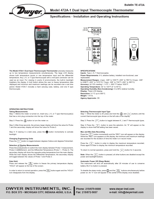
OPERATING INSTRUCTIONSTaking MeasurementsStep 1: Before the meter is turned on, insert any J, K, or T type thermocouple(s)that has a mini plug connection into the top of the meter.Step 2: Press the button to turn the meter on.Step 3: After three seconds, the primary larger display will show the value for Probe1 and the secondary display will show the value for Probe 2.Step 4: If viewing in a dark area, press the button momentarily to activatebacklight.Changing Engineering UnitsPress the button to toggle between degrees Celsius and degrees Fahrenheit.Selection of Display MeasurementsPress the button to switch the main display between Probe 1 measurement,Probe 2 measurement, and the Differential Temperature (Probe 1 – Probe 2). Thesecondary display will show the opposite probe temperature from the main display.While the main display shows the Differential Temperature, the secondary displaywill toggle between the values of Probe 1 and Probe 2.Data HoldPress and release the button to freeze the primary temperature display.“HOLD” will appear at the top of the screen.In order to return to normal operation, press the button again and the “HOLD”icon disappears from the display.The Model 472A-1 Dual Input Thermocouple Thermometer precisely measuresup to two temperature measurements simultaneously. The large LCD displayshows both temperature inputs or one temperature input and the differentialtemperature. Any J, K, or T type thermocouple with a mini-jack connector can beused as an input. For viewing in poorly lit environments, the built-in backlightbrightens the display. A hold button allows the user to freeze temperature datadisplayed and minimum and maximum readings can be recorded over a set timeperiod. Model 472A-1 includes a hard carrying case, battery, and one K typethermocouple.SPECIFICATIONSInputs: Type J, K, T thermocouples.Power Requirements: 9 V, alkaline battery, installed non-functional, userreplaceable.Measurement Ranges: J-type: -328° to 1400°F (-200° to 760°C); K-type: -328°to 2498°F (-200° to 1370°C); T-type: -328° to 734°F (-200° to 390°C);Accuracy: ±0.13%reading + 1.4°F + .006°/°F below 1000°F.Operating Temperature: 32° to 122°F (0° to 50°C).Operating Humidity (Non-Condensing): 0 to 85% relative humidity.Display:Triple LCD display.Resolution:0.1°C up to 500°C.Weight:1.47 lb.Agency Approvals: CE.[29.08][65.79]15/16RELHOLDRELHOLD°C/°FCHANNELDWYER INSTRUMENTS, INC.Phone: 219/Fax: 219/872-9057e-mail:******************©Copyright 2015 Dwyer Instruments, Inc.Printed in U.S.A. 5/15FR# 443743-00 Rev. 4BATTERY REPLACEMENTThe Dual Input Thermocouple Thermometer displays “BAT” as a visual low battery indication.To Replace the Battery:1. Make sure the unit is powered off.2. Remove thermocouples from the top of the instrument.3. Lay face down on a clean, flat surface.4. Open battery compartment by pushing in tab and lifting cover.5. Replace battery, taking note of the indicated polarity.6. Replace the cover.MAINTENANCEA periodic check of the system calibration is recommended. Model 472A-1 is not field serviceable and should be returned if repair is needed (field repair should not be attempted and may void warranty). Be sure to include a brief description of the problem plus any relevant application notes. Contact customer service to receive a return goods authorization number before shipping.If the thermometer fails to power on, it is likely that the batteries also need to be replaced.Failing to turn the thermometer off may result in malfunction of the unit. Dispose of used battery promptly and keep away fromchildren.。
BG-thermoRT说明书

BG-thermoRT干式恒温器使用说明书目录第一章产品介绍...............................................................1.1简介...............................................................1.2安全注意事项............................................................1.3质保1.4结构组成1.5技术指标第二章面板说明第三章操作程序...............................................................第四章疑难排解第五章维护保养...............................................................第六章运输、贮存第一章产品介绍1.1 简介BG-thermoRT干式恒温器一般作为实验室加热(或温)试管或其它微小容器的常规装置。
温控精确,操作简单。
现广泛用于分子生物学、微生物学等常规实验中。
产品特点:即时温度显示、时间递减显示功能温度、时间设定功能,可设置多节控制具有自动故障检测及报警功能控制时间运行结束后蜂鸣器报警提示功能温度偏差校准功能便捷的模块更换,便于清洁与消毒内置超温保护装置具有暂停/继续转换功能1.2安全注意事项重要安全操作信息!使用前请认真仔细阅读!本手册包含重要操作和安全使用信息!为了更好的使用本仪器,使用前请认真仔细阅读和了解本手册内容!仪器未使用时,请将仪器开关处于关闭状态并和电源断开!使用前,请检查仪器开关是否处于关闭状态!不要在湿度大于95%时使用,否则内部可能会产生短路,从而使电源烧毁!电源从高温室移动到低温室时,可以马上使用;但从低温室移动到高温室时,请放置2h后再使用。
为安全起见,请用随机所配的电源线!另外,请检查电源线是否有连接松动、胶皮破损、导线腐蚀、导线断开等现象,以免使用时对人体产生危害!仪器仅供使用本手册所说明的目的!在导线或者仪器损坏时,请不要继续使用本产品!移动本产品时请断开电源!使用时,如有异常电压或着声音等现象,请马上断开电源并联系本公司或者当地办事处,不要私自打开维修!注意:本公司不对任何由于不按照说明书使用而导致的后果负责!1.3质保1)产品自售出之日起,整机免费保修一年。
恒温加热器使用说明书

恒温加热器使用说明书一、产品介绍恒温加热器是一种用于控制温度的设备,适用于实验室、工业生产等领域。
本产品采用先进的温度传感器和控制技术,能够实现精确的温度控制,具有稳定性好、操作简单等特点。
二、安全注意事项1. 本产品需在干燥、通风良好的环境下使用。
2. 请确保电源连接正确,接地可靠,以确保使用安全。
3. 仔细阅读产品说明书,并按照说明进行正确操作,避免不必要的事故发生。
4. 使用过程中应避免遮挡散热孔,避免过载使用。
5. 使用结束后,请拔掉电源插头,确保设备断电。
三、产品特点1. 温控范围广:本产品的温控范围可根据需要进行调整,满足不同的实验需求。
2. 温度稳定性好:经过精确的温度控制算法设计,保证设备稳定运行,提供精确的温度控制。
3. 操作简单:本产品采用触摸屏设计,界面简洁清晰,操作便捷,即使对设备不熟悉的用户也能够轻松上手使用。
4. 故障自诊断:设备具有故障自诊断功能,一旦出现故障,会自动报警并显示故障原因,方便用户快速排除故障。
四、使用方法1. 打开设备:接通电源后,按下电源按钮,待设备开机完成后进入待机状态。
2. 设置温度:通过触摸屏上的温度调节按钮,可自定义所需温度。
设定后,系统会根据设定值进行温度控制。
3. 启动加热:设定好温度后,点击启动加热按钮,设备将开始加热,并根据设定温度进行温度调节。
4. 监控温度:设备运行时,观察触摸屏上显示的实时温度值,确保温度始终在设定范围内。
5. 结束使用:使用完毕后,点击停止加热按钮,设备会停止加热并保持待机状态。
拔掉电源插头,确保设备断电。
五、故障排除1. 故障自诊断:设备出现故障时,会自动报警并显示故障原因,用户可根据报警信息进行故障排除。
2. 联系售后服务:若设备故障无法解决,请联系售后服务中心进行维修或更换。
六、维护保养1. 定期清洁:使用过程中请保持设备干燥,避免积尘。
定期用软布擦拭设备外壳,以保持清洁。
2. 防止碰撞:使用过程中请避免撞击设备,以免损坏设备外壳或内部元件。
Pro1 TT-N-705 and T705 恒温器说明书

Thermostat Quick Reference Thermostat Operation ProgrammingContact Us and Warranty Registration2346Congratulations on purchasing a new thermostat. This thermostat was designed to the highest reliability and ease of use standards. Thank you for choosing Pro1.® U.S. Registered Trademark. Patents pending.Copyright © 2006 Pro1 IAQ, Inc. All rights reserved.Rev. 0850Table of ContentsPage1Need Help?For assistance with this product please visit or call Pro1 Customer Care toll-free at 888-Pro1iaq (776-1427) during normal business hours (Mon-Fri 9 AM - 6 PM Eastern)Una versión española de este manual puede ser descargada en Battery door information2Use the finger bevel onbattery door.Important:The low battery indicator is displayed when the AA battery power is low. If the user fails to replace the battery within 21 days, the thermostatdisplay will only show the low battery indicator as a final warning before the thermostat becomes inoperable.Getting to know your thermostatLCD12Fan Switch 3System Switch4Easy Change Battery Door 5Setpoint Buttons 6User Buttons7Displays the user selectable setpoint System operationindicators: The COOL, HEAT or FAN icon will display when the COOL, HEAT or FAN is on.NOTE: The compressor delay feature is active if these icons are flashing. The compressor will not turn on until the 5 minute delay has elapsed.Days of the week and timeButton Glow in the Dark Light Button 6712345Low Battery Indicator: Replace batteries when indicator is shown.room temperature.Period Icons: This thermostat has 4 programmable time periods per day.3Easy to use controlsLCD Display:See page 2 for details about this display read out and icons.12345Glow in the Dark Light Button:The glow in the dark light button will self illuminate for several hours after exposure to ambient light. This button turns on the display light when pressed.Temperature Setpoint Buttons:Press the + or - buttons to select the desired room temperature.6User Buttons:Use these buttons to set up your programming options. Refer to the next page for instructions.Fan Switch:Select ON or AUTO . ON will runthe fan continuously. AUTO will cycle the fan on only when the heating or cooling system is on.System Switch:Selects the operation mode of your HVAC system. Selecting HEAT turns on the heat mode. Selecting COOL turns on the air conditioning mode. Selecting OFF turns both heating and cooling off.6123454Set TimeFollow the steps below to set the current time:Press MENU Press SET TIMEPressNEXT STEPcorrect a.m. or p.m. choice is selected.Press NEXT STEPPress DONE when completed1.2.3.4.5.6.7.8.Set Program ScheduleTo customize your program schedule, follow these steps Weekday:Saturday:Sunday:Select HEAT or COOL from the system switch. Note: You have to program heat and cool each separately.Press MENUPress SET SCHED . Note: Monday-Friday is displayed and the WAKE icon is shown. You are now program-ming the wake time period for the weekday setting.time period.Press NEXT STEPwake period.Press NEXT STEPRepeat steps 4 through 7 for weekday LEAVE time period, for weekday RETURN time period, and for weekday SLEEP time period.Repeat steps 4 through 7 for Saturday WAKE time period, for Saturday LEAVE time period, for Saturday RETURN time period, and for Saturday SLEEP time period.Repeat steps 4 through 7 forSunday WAKE time period, for Sunday LEAVE timeperiod, for Sunday RETURN time period, and for Sunday SLEEP time period.1.2.3.4.5.6.7.8.9.10.5Temporary and Permanent Hold FeatureFilter Change ReminderIf your installing contractor has configured the thermostat to remind you when the air filter needs changed, you will see FILT in the display when your air filter needs changed. FILT will be shown in the display after your system has run long enough to require an air filter change.Resetting the filter change reminder: When FILT reminder is displayed, you shouldchange your air filter and reset the reminder by holding down the second button from the top left side of the thermostat for 3 seconds.Temporary hold: The thermostat will display HOLD and RUN SCHEDscreen when you press thekey.at this setpoint temporarily until the next program period begins. Your program setpoint will then replace your temporarysetpoint.Permanent hold: If you press HOLD , you will see HOLD appear below the setpoint tem-perature in the display. The thermostat will be adjusted using the keys. To return to program: Press RUN SCHED to exit either temporary or permanent hold.Hold down for 3 seconds, to reset filter reminder.Name: ____________________________Address: ________________________________________________________City: ____________________________State: ____________________________Zip:_____________________Thermostat Model: _____________________Date Installed:_____________________6Contact Us InformationPro1 IAQ Warranty Registration:Pro1 IAQ Inc.1111 S. Glenstone Suite 2-100Spring eld, MO 65804Toll-free: 1-888-Pro1iaq (776-1427)Toll Number (Outside the USA): 330-821-3600Web: Hours of Operation: Monday - Friday 9 AM - 6 PM EasternComplete form and mail to:Pro1 IAQ Inc.1111 S. Glenstone Suite 2-100Spring eld, MO 65804。
恒温制冷制冷系统辅助电热器安装说明书

Manufacturer reserves the right to discontinue,or change at any time,specifications or designs without notice and without incurring obligations.PC 111Catalog No.535-00142Printed in U.S.A.Form 50H,P-1SI Pg 16-05Replaces:50HG-2SI Book 14T ab 1b 6bCancels:NewIIK 551A-210-36/1/05Installation InstructionsPart Numbers:CRHEA TER144B00-CRHEA TER155B00The electric heater accessory is used on the followingunits:SAFETY CONSIDERATIONSRead these instructions entirely before installing the acces-sory electric heaters on the base rooftop unit.See Table 1for Installation and servicing of air-conditioning equipment can be hazardous due to system pressure and electrical compo-nents.Only trained and qualified service personnel should install,repair,or service air-conditioning equipment.Untrained personnel can perform the basic maintenance functions of replacing filters.All other operations should be performed by trained service personnel.When working onair-conditioning equipment,observe precautions in the litera-ture,tags and labels attached to the unit,and other safety pre-cautions that may apply.Follow all safety codes.Wear safety glasses and work e quenching cloth for unbrazing operations.Have GENERALThis installation instruction covers accessory heaters CRHEA TER144B00through CRHEA TER155B00.Each kit contains the heater module,block-off plate,1or 2conduit assem-blies,wire ties,and the wiring label.The CRHEA TER153B00accessory kit contains a terminal block in addition to these parts.See Table 1for unit electrical data and kit usage.NOTE:All units with electric heat require a field-supplied 90-degree elbow.The elbow must be installed in the supply ductwork below the unit discharge connection.NOTE:CRHEA TER153B00(75kW,240volt)requires a dual-point power supply.Table 1—Electrical Data and Electric Heater Package Usage*kW rated at 240,480,and 600volts.IMPORTANT:Read these installation instructions thor-oughly BEFORE starting installation.UNIT SIZE 50HG 014-02850HJ 020-02850PG 20-28551A210-300ACCESSORY HEATERPART NUMBER UNIT 50HGHEATER/BASE UNITVOLTAGE HEATER kW*STAGESCRHEATER144B0050HG014208/230-3-60161CRHEATER145B0050HG014460-3-60151CRHEATER146B0050HG014575-3-60161CRHEATER147B0050HG014-028,50HJ020-028,50PG20-28,551A210-300208/230-3-60252CRHEATER148B0050HG014-028,50HJ020-028,50PG20-28,551A210-300460-3-60252CRHEATER149B0050HG014-028,50HJ020-028,50PG20-28,551A210-300575-3-60252CRHEATER150B0050HG014-028,50HJ020-028,50PG20-28,551A210-300208/230-3-60502CRHEATER151B0050HG014-028,50HJ020-028,50PG20-28,551A210-300460-3-60502CRHEATER152B0050HG014-028,50HJ020-028,50PG20-28,551A210-300575-3-60482CRHEATER153B0050HG016-028,50HJ020-028,50PG20-28,551A210-300208/230-3-60752CRHEATER154B0050HG016-028,50HJ020-028,50PG20-28,551A210-300460-3-60752CRHEATER155B0050HG016-028,50HJ020-028,50PG20-28,551A210-300575-3-60782Single Package Rooftop Units121/2to 25TonsElectric Heater Accessory2INSTALLATIONDual Point Electrical Service Connection (CRHEATER153B00Only)—The CRHEA TER153B00electric heat accessory kit (75kW ,240volt)requires an electri-cal service connection independent from all other electrical circuits in the unit.This electrical service should be sized in accordance with the following heater rating:LEGENDTo install dual point service connection,perform the follow-ing procedure:1.Turn off power to the unit.2.Install auxiliary terminal block in compressor compart-ment (Fig.1).3.Connect electrical service to terminal block.4.Connect ring-terminal end of conduit to the terminal block enclosure.5.Connect ring terminals to terminal block.6.Continue with Heater Installation section.Heater Installation (All Units)—Perform the fol-lowing procedure to install the accessory electric heaters:1.Turn off power to the unit.2.Remove electric heater section access panel from base rooftop unit.See Fig.2.3.For all units with the SA T (supply-air thermistor)in the heat section,remove the block-off plate and SA T from electric heater compartment and save screws (Fig.2).Units with the SA T in the supply blower do not need relocation.4.Remove the block-off plate from the right side of the filter block-off panel.Remove and re-orient the conduit bracket installed on the unit in either the one or two conduit orientation appropriate for the application (see Fig.3).5.The bracket on the condensate pan must be removed.In order to remove the bracket on the condensate pan,the filter shroud must first be removed (see Fig.4).Next,remove the bracket under the left side of the condensate pan exposing the two-conduit slot (see Fig.3).For units that use only one conduit,rotate the bracket 180degrees and reinstall leaving half of the slot exposed.Reinstall the filter shroud.6.Route conduit from control box to heater compartment passing through the slots exposed in Steps 4and 5(Fig.5).NOTE:The end of the conduit with ring terminals should be toward the compressor end of the unit and the other end toward the heater compartment.7.Thread one end of conduit to the heater section partition.Thread the other end to bottom of unit control box (except CRHEA TER153B00).8.Slide heater module into heater compartment by aligning the hanging bracket on end of heater with center rail in unit heating compartment (see Fig.6and 7).Do not push the heater all the way in at this time.9.If required,route the SA T through the hole in top of elec-tric heater control box.10.Feed power wiring into heater control box and slide theheater into final position.11.Secure electric heater control box to unit using screwsfrom Step 3.Heater will attach to holes in the back of the electric heat control box.12.If required,install SA T through the back of electric heatercontrol box using the screws saved from Step 3.Secure the SA T wire to the top of the control box with the pro-vided wire-tie.SAT location is shown in Fig.2.13.Remove jumper wire from 6-pin plug and connect controlwires to plug in heater compartment partition.NOTE:The mounting plate for the 6-pin plug may be removed temporarily to increase access to make this connection.Be sure to reinstall the mounting plate before proceeding.14.Connect power wires to terminal blocks in accordancewith the appropriate heater wiring diagram.(See Fig 8.)15.Connect power wires to terminal block in unit con-trol box (or dual-point service enclosure for CRHEATER153B00).Refer to wiring diagram.16.Reinstall electric heater section access panel.17.Apply wiring label to inside of compressor compartmentdoor.18.Apply power to unit.VOLTS MCA MOCP 208/240156/180175/200MCA —Minimum Circuit AmpsMOCP —Maximum OvercurrentProtection34567Configuring Units with C omfort Link™Control (50HG,PG Units)—The Comfor tLink control must nowbe configured to operate the electric heaters.The Comfort Link control must be configured for Electric Heat (default is No Heat).In addition,if a 15-kW electric heater has been installed,it will be necessary to change the N.HTR configuration from 2to 1(2is the default setting).These configurations are changed through the Scrolling Marquee Display by using the Configu-ration menu.See Table 2.NOTE:Consult the Controls and Troubleshooting Guide for in depth instructions on using and configuring the Comfort Link control.1.The Comfort Link control must be configured to use the electric heater accessory.A password may be required to edit the configurations depending on the previous settings configured in the unit.Default password is “1111”.2.To configure the Comfort Link control,use the arrow keys to scroll the red LED on the display to the “Configura-tion ”position and press .e the arrow keys to scroll down until the display shows “HEAT ”.This is the Heating Configuration submode.Press .4.The Comfort Link control will display the Type of Heat (HT.TY )setting.Press once to select the HT.TY setting for configuration.Press again.A “0”will begin flashing.e the arrow keys to change the configuration from “0”(No Heat)to “2”(Electric Heat)and press .Press to save the setting.6.For 15-kW single-stage electric heaters only,the Number of Heat Stages must be changed from 2to 1.e the arrow keys to scroll down to the Number of Heat Stages setting (N.HTR ).Press to select the N.HTR setting for configuration.b.Press again.Configuration value willflash.e the arrow keys to change the configurationfrom “2”(2stages of heat)to “1”(one stage of heat)and press .d.Press to save the configuration change.7.Configuration of Comfort Link control is now complete.Pressing multiple times will return the display to the auto-scroll setting.8.Close and secure all access doors.Table 2—Comfort Link Heat ConfigurationENTER ENTER ENTER ENTER ENTER ESCAPE ENTER ENTER ENTER ESCAPE ESCAPE ITEME X PANSIONRANGEUNITSCCN TABLE/SUB -TABLE CCN POINTDEFAULTCONFIGURATIONSERVICECONFIGURATION HEAT Heating Configuration HEAT_CFG→HT.TY Type of Heat Installed0=No Heat 1=Gas 2=Electric HEATTYPE0(50series with no electric heat)1(48series)2(50series with electric heat)→N.HTR Number of Heat Stages 1to 2NUM_HEAT 2→MRT.H Heat Minimum On Time 60to 999sec HMIN_ON 120→MOT .H Heat Minimum Off Time 60to 999sec HMIN_OFF 120→H.DEC Heat Stage Decrease Rate 120to 999sec HST AGDEC 300→H.INC Heat Stage Increase Rate 120to 999sec HST AGINC 450→FOD.E Fan-off Delay,Elect Heat 10to 600sec ELEC_FOD 30→FOD.G Fan-off Delay,Gas Heat 45to 600sec GAS_FOD 45→HT.LO Heating Lockout T emp 40to 125dF OATLHEAT 75→SAT.H SAT Heat Mode Sensing Enable/Disable SAT_HEAT Disable →SPT Space Temperature Sensor →HT .PD SPT Heat Demand (+)Level 0.5to 5^F HDEM_POS 1→HT .ND SPT Heat Demand (–)Level –5to –0.5^F HDEM_NEG –1→G Heat Thermal Lag Factor0to 5minHEAT_LAG1Copyright2005Carrier CorporationManufacturer reserves the right to discontinue,or change at any time,specifications or designs without notice and without incurring obligations.PC111Catalog No.535-00142Printed in U.S.A.Form50H,P-1SI Pg86-05Replaces:50HG-2SI Book14Tab1b6b。
恒温电器高效性能双阶段气炉说明书

Specifications are subject to change without notice.440 71 4321 04 May 2013Up to 96% AFUE, Two −Stage ECM Gas FurnaceEASIER TO SELLS Up to 96% AFUE, all models, all positions S California NOxapprovedS All Models have earned the ENERGY STAR R S Two −stage heating operation S Xtra SEER ECM blower motorS Supports single − and two −stage cooling unitsS Approved for Twinning applications (0601412 through 1202422)S Dehumidification feature in cooling S Electronic air cleaner terminalS Certified to leak 2% or less of nominal air conditioning CFM delivered when pressurized to 1−inch water column with all present air inlets and outlets, and condensate drain port(s) sealedTOUGHERS Flame roll −out sensors standardS Adjustable heating blower OFF delay S Factory set blower ON delayS Stainless steel secondary heat exchangerS High temperature limit control prevents overheating S Direct ignition with Silicon Nitride ignitorS High −quality, corrosion −resistant, one −piece steel cabinet QUIETERS Operates quieter at lower heating ratesS Two −speed induced draft combustion blower S Fully Insulated steel cabinetEASIER TO INSTALL AND SERVICES Direct vent (2−pipe), single −pipe venting or ventilated combustion air S 24 VAC humidifier terminalS 35” (889mm) high, for ease of installationS Innovative knobs for easy door removal and secure attachment S Factory shipped for natural gas, with propanegas conversion kits available S Four position − upflow/downflow/horizontal (left/right) installationS At least twelve different venting configurations S Through the casing flue pipe for counterflowor horizontal applications with accessory (order separately)S Concentric vent availableS Self diagnostics with super bright LEDS Slide out heat exchanger assembly and blower assemblyWARRANTY *S 5 year No Hassle Replacement t limited warrantyS Lifetime heat exchanger limited warranty S 5 year parts limited warrantyIllustrations and photographs are only representative.Use of the AHRI Certified TM Mark indicates a manufacturer’s participation in the program. For verification of certification for individual products,go to .THIS MODEL96−With timely registration, an additional 5 year parts limited warranty*For owner occupied, residential applications only. See warranty certificate for complete details and restrictions, including warranty coverage for other applications.Model NumberInput (BTUH)Efficiency AFUE Cooling CapacityCFM range @ .5 in. w.c. (125 Pa)Dimensions H x W x D Inches (Millimeters)Shipping Wt. Lbs (Kg)G9MXT0401410A 40,00096%385−92535 x 14-3/16 x 29−1/2 (889 x 361 x 750)125 (56)G9MXT0401712A 40,00096%330−108535 x 17−1/2 x 29−1/2 (889 x 445 x 737)135 (61)G9MXT0601412A 60,00095.5%620−109035 x 14-3/16 x 29−1/2 (889 x 361 x 750)136 (62)G9MXT0601714A 60,00096%530−150535 x 17−1/2 x 29−1/2 (889 x 445 x 737)146 (66)G9MXT0801716A 80,00096%920−161035 x 17−1/2 x 29−1/2 (889 x 445 x 737)156 (70)G9MXT0802120A 80,00096%795−201535 x 21 x 29−1/2 (889 x 533 x 737)161 (73)G9MXT1002120A 100,00096%1105−211035 x 21 x 29−1/2 (889 x 533 x 737)171 (77)G9MXT1202422A120,00096%1215−205535 x 24−1/2 x 29−1/2 (889 x 622 x 737)195 (88)G9MXTProduct SpecificationsPRODUCT SPECIFICATIONSGas Furnace: G9MXT2440 71 4321 04Specifications subject to change without notice.MODEL NUMBER IDENTIFICATION GUIDEDIGIT POSITION 123456,7,89,1011,121314G = Mainline G 9M X T 0601714A 1N = Entry9 = 90+% AFUE EFFICIENCY M = MultipositionPOSITIONA = Modulating ECM Variable Speed BlowerV = ECM Variable SpeedX = ECM Blower (Speed Select) S = Single −stageT = Two −stageTYPEC = CommunicatingE = Extra AFUE EfficiencyT = Two −StageFEATURE040 = 40,000 BTU/hr 060 = 60,000 BTU/hr 080 = 80,000 BTU/hr 100 = 100,000 BTU/hr120 = 120,000 BTU/hr HEAT INPUT14 = 14−3/16”17 = 17−1/2”21 = 21”24 = 24−1/2”CABINET WIDTH08 = 800 CFM 10 = 1000 CFM 12 = 1200 CFM 14 = 1400 CFM 16 = 1600 CFM 20 = 2000 CFM22 = 2200 CFMNOMINAL MAXIMUM COOLING AIRFLOW @ .5 IN. W.C.SALES (MAJOR) REVISION DIGITENGINEERING (MINOR) REVISION DIGITECM−Electronically Commutated Motor ACCESSORIES PART NUMBER IDENTIFICATION GUIDEDIGIT POSITION12345, 6, 78, 910, 11NA H A 00101DHN = Non −Branded BRANDINGA = Accessory PRODUCT GROUPH = Heating KIT USAGEA = OriginalB = 2nd Generation MAJOR SERIESProduct Identifier Number Package QuantityType of Kit (Example: DH = Draft Hood − Chimney Adapter)PRODUCT SPECIFICATIONSGas Furnace: G9MXT440 71 4321 043Specifications subject to change without notice.PHYSICAL DATAUNIT SIZE(NATURAL GAS Ratings)0401410A 0401712A 0601412A 0601714A 0801716A 0802120A 1002120A 1202422A Input High Heat (BTUH)40,00040,00060,00060,00080,00080,000100,000120,000Low Heat (BTUH)26,00026,00039,00039,00052,00052,00065,00078,000Output High Heat (BTUH)39,00039,00058,00058,00078,00078,00097,000117,000Low Heat(BTUH)25,00025,00038,00038,00050,00051,00063,00076,000EfficiencyAFUE % (ICS)96.095.596.0Certified Temperature Rise Range ºF (ºC)High Heat 40−70(22−39)40−70(22−39)35−65(19−36)40−70(22−39)40−70(22−39)40−70(22−39)40−70(22−39)40−70(22−39)Low Heat30−60(17−33)30−60(17−33)30−60(17−33)30−60(17−33)30−60(17−33)30−60(17−33)30−60(17−33)30−60(17−33)ICS — Isolated Combustion SystemAIRFLOW CAPACITY AND BLOWER DATAUNIT SIZE0401410A 0401712A 0601412A 0601714A 0801716A 0802120A 1002120A 1202422A Rated External Static Pressure in.w.c.(kPa)Heating .10 (.025).10 (.025).12 (.030).12 (.030).15 (.038).15 (.038).20 (.050).20 (.050)Cooling .5 (.125)Airflow Delivery @Rated ESP (CFM)High Heat 69570594010001360136017002125Low Heat 5905807757851095105513251610Cooling 9251085109015051610201521102055Cooling Capacity (tons) @400, 350 CFM/ton400 CFM/ton 2 2.5 2.5 3.54555350 CFM/ton2.5334 4.5 5.566Direct −Drive Motor Type Electronically Commutated Motor (ECM)Direct −Drive Motor HP 1/21/21/23/43/4111Motor Full Load Amps 6.86.86.88.48.410.910.910.9RPM Range 600 − 1200Speed Selections 5Blower Wheel Dia x Width inches11 x 711 x 811 x 711 x 811 x 811 x 1011 x 1011 x 11Air Filtration SystemField SuppliedFilter Used for Certified Watt DataNAHA00506FBNAHA00706FBCONTROLSUNIT SIZE0401410A0401712A0601412A0601714A0801716A0802120A1002120A1202422AGas Connection Size 1/2” − NPT Burners (Monoport)22334456Gas Valve (Redundant)ManufacturerWhite Rodgers tMinimum Inlet Gas pressurein. w.c. (kPa) 4.5 (1.1)Maximum Inlet Gas pressurein. w.c. (kPa)13.6 (3.4)Gas Conversion Kit Natural to Propane NAHA01001LP Gas Conversion Kit Propane to Natural NAHA01001NG Ignition DeviceSilicon NitrideLimit Control165180165180170200180160Htg Blower Control (Htg Off −Delay)Adjustable: 90, 120, 150, 180 secondsClg Blower Control (Time Delay Relay)90 secondsThermostat Connections R, W/W1, W2, Y1, Y/Y2, G, DHUM, CAccessory ConnectionsEAC (115vac); HUM (24vac); 1−stg AC (via Y/Y2)PRODUCT SPECIFICATIONSGas Furnace: G9MXT4440 71 4321 04Specifications subject to change without notice.ELECTRICAL DATAUNIT SIZE0401410A0401712A0601412A0601714A0801716A0802120A1002120A1202422AInput Voltage (Volts −Hertz −Phase)115−60−1Operating Voltage Range Min.−Max.104 − 127Maximum Input Amps Amps 7.57.57.69.29.211.711.811.8Unit AmpacityAmps 10.310.310.412.412.415.515.615.6Minimum Wire SizeAWG 1414141414121212Maximum Wire Length @ Min Wire SizeFeet (M)36 (11.0)36 (11.0)35 (10.7)29 (8.8)29 (8.8)37 (13.3)36 (10.7)36 (11.0)Maximum Fuse/Circuit Breaker (Time −Delay Type Recommended)Amps1515151515202020Transformer Capacity24 VAC Output / 40 VAExternal Control Power AvailableHeating 24.3 VACooling 34.6 VAFURNACE SIZEABC D SHIP WT.LB (KG)CABINET WIDTH OUTLET WIDTH BOTTOM INLET WIDTH AIR INTAKE 040141014−3/16 (361)12−1/2 (319)12−9/16 (322)7−1/8 (181)125 (56)040171217−1/2 (445)15−7/8 (403)16 (406)8−3/4 (222)135 (61)060141214−3/16 (361)12−1/2 (319)12−9/16 (322)7−1/8 (181)136 (62)060171417−1/2 (445)15−7/8 (403)16 (406)8−3/4 (222)146 (66)080171617−1/2 (445)15−7/8 (403)16 (406)8−3/4 (222)156 (70)080212021 (533)19−3/8 (492)19−1/2 (495)10−1/2 (267)161 (73)100212021 (533)19−3/8 (492)19−1/2 (495)10−1/2 (267)171 (77)120242224−1/2 (622)22−7/8 (581)23 (584)12−1/4 (311)195 (88)MINIMUM CLEARANCES TO COMBUSTIBLE MATERIALS FOR ALL UNITSPOSITION CLEARANCE in.(mm)REAR 0FRONT (Combustion air openings in furnace and in structure) 1 (25)Required for service *24 (610)All Sides of Supply Plenum *1 (25)Sides 0Vent 0Top of Furnace 1 (25)* Consult your local building codes.PRODUCT SPECIFICATIONS Gas Furnace: G9MXT440 71 4321 045Specifications subject to change without notice.PRODUCT SPECIFICATIONSGas Furnace: G9MXT6440 71 4321 04Specifications subject to change without notice.AIR DELIVERY − CFM (with filter)UNIT SIZERETURN-AIR CONNECTIONSPEED TAPS 2EXTERNAL STATIC PRESSURE (in. w.c.)0.10.20.30.40.50.60.70.80.9 1.00401410SIDE/BOTTOMGray 112010801030980925875820760690630Yellow880845810780740710680640615570Blue 695665620575535495455420370280Orange 640595540495460420370310260230Red 570525475425385330255220- 6- 60401712SIDE/BOTTOMGray 125512201175113010851040990940880825Yellow940905870840805770735695665630Blue 705670630575540500455410380325Orange 580535480425380335290235- 6- 6Red 555485425375330280215- 6- 6- 60601412SIDE/BOTTOMGray 126512251185114010901030975920850760Yellow11151085106010301000970930880810715Orange 1000970940910880845815770735695Blue 945915885855820785745705675635Red 7707407006606205755405004554150601714SIDE/BOTTOMGray 1720167016201565150514401375129512201135Yellow1325128512551220118511451115107510401000Blue 1010970925875835785745690660620Orange 11601115108010451000960920875840785Red 7857156555955304904353853402850801716SIDE/BOTTOMGray 1810177017201665161015401475140013151235Yellow1535150014751435140513701340131012451160Blue 1380134013051270124012001165113010901050Orange 11801130109510601015975935895850800Red 1100104510109709208858457907456900802120BOTTOM or TWO-SIDES 4, 5Gray2290222521552090201519301845175016401515Yellow 1810176017251685164016001555152014801415Blue 13851340128512401200114010901050995950Orange 1560152014751430138513351295124012001150Red 10559859108607957506806155654951002120BOTTOM or TWO-SIDES 4, 5Gray2340229522502195211020301935183517251605Yellow 1950190018551800175517051655160515601485Blue 1750170016501605155515001455139513501300Orange 1570152014601410135013001240119511401095Red 13501280122511551105104510009508958301202422BOTTOM or TWO-SIDES 4, 5Gray2275223021852130205519501825171016101500Yellow 1875182017701720166016001550150514501390Blue 2170212520752025197519001790169515901470Orange 314751420135012801215116511051050995930Red 31625156515051445138513251275122511701130NOTE :1.A filter is required for each return −air inlet. Airflow performance includes a 3/4 in. (19 mm) washable filter media such as contained in factory −authorized accessory filter rack. See accessory list. To determine airflow performance without this filter, assume an additional 0.1 in. W.C. available external static pressure.2.ADJUST THE BLOWER SPEED TAPS AS NECESSARY FOR THE PROPER AIR TEMPERATURE RISE FOR EACH INSTALLATION.3.Shaded areas indicate that this airflow range is BELOW THE RANGE ALLOWED FOR HIGH −STAGE HEATING OPERATION . THESE AIRFLOW RANGES MAY ONLY BE USED FOR LOW −STAGE HEAT OR COOLING.4.Airflows over 1800 CFM require bottom return, two −side return, or bottom and side return. A minimum filter size of 20” x 25” is required.5.For upflow applications, air entering from one side into both the side of the furnace and a return air base counts as a side and bottom return.6.The ”−” entry indicates an unstable operating condition.PRODUCT SPECIFICATIONSGas Furnace: G9MXT7440 71 4321 04Copyright 2013 International Comfort ProductsLewisburg, Tennessee 37091 USA A C C E S S O R I E SP A R T N U M B E R C O M P O N E N T N A M ED E S C R I P T I O N 04014100401712060141206017140801716080212010021201202422N A H A 00101C T E X T E R N A L T R A P K I TC O NDE N S A T E T R A PXX X X X X X XN A H A 00110D A D R A I N A C C E S S O R Y1/2” C P V C T O 3/4” P V C (10 P A C K )XX X X X X X XN A H A 002C VV E N T T E R M I N A T I O N K I T2” C O N C E N T R I C V E N TXX X X X X XN A H A 001C V3” C O N C E N T R I C V E N TXX X X XXN A H A 00101V C I N T E R N A L V E N T K I TT H R O U G H T H E C A B I N E TXX X X X X XXN A H A 00301V TD I RE C T V E N T T E R M I N A T I O N K I T2” B R A C K E TXX X X X X XN A H A 00401V T3” B R A C K E TXX X XXXN A H A 00101C K I N L E T A I R P I P E C O U P L I N GC O U P L I N G F O R P O L Y P R O P Y L E N E V E N T S Y S T E M SXX X X X XXXN A H A 00101H V H O R I Z O N T A L I N S T A L L A T I O N K I TT R A P G R O M M E T (D I R E C T V E N T A P P L I C A T I O N O N L Y )XX X X X XXXN A H A 00101H H F R E E Z E P R O T E C T K I TC O NDE N S A T E D R A I N L I N E − T A P EXX X X XXXXN A H A 00201H H C O N D E N S A T E F R E E Z E P R O T E C T K I TC O NDE N S A T E T R A P W I T H H E A T P A DXX X X XXXXN A H A 01101S B F L O O R B A S E K I TC O M B U S T I B L E F L O O RXX X X XXXXN A H B 01001L P *G A S C O N V E R S I O N K I TN A T U R A L T O P R O P A N EXX X X XXXXN A H B 01001N G *P R O P A N E T O N A T U R A LXX X XXXXXN A H A 00701W K T W I N N I N G K I TO P E R A T I O N O F T W O I D E N T I C A L S I Z E M O D E L F U R N A C E SXXXXXXN A H A 00506F B †W A S H A B L E F I L T E R P A C KW A S H A B L E F I L T E R 1” X 16” X 25” (6 P A C K )XX XXXN A H A 00706F BW A S H A B L E F I L T E R 1” X 24” X 25” (6 P A C K )X X XN A H B 00501F FE X T E R N A L B O T T O MF I L T E R R A C K14” X 25” W A S H A B L E F I L T E R I N C L U D E DXXN A H B 00601F F17−1/2” X 25” W A S H A B L E F I L T E R I N C L U D E DX X XN A H B 00701F F21” X 25” W A S H A B L E F I L T E R I N C L U D E DXXN A H B 00801F F24−1/2“ X 25” W A S H A B L E F I L T E R I N C L U D E DXN A H A 00901F F A D J U S T A B L E S I D E F I L T E R R A C K1” W A S H A B L E F I L T E R I N C L U D E DXXXXXXXXN A H B 00101C AC O I L AD A P TE R K I TW I T H N O O F F S E TXXXXXXXXN A H B 00201C A W I T H S I N G L E O F F S E TXXXXXXXXN A H B 00301C AW I T H D O U B L E O F F S E TXXXXXXXXN A H A 01401R AR E T U R N A I R K I T14−3/16” W I D EXXN A H A 01701R A17−1/2” W I D EXX XN A H A 02101R A21” W I D EXXN A H A 02401R A24−1/2” W I D EXN A H A 001N K C O N D E N S A T E N E U T R A L I Z E R K I TN E U T R A L I Z E S C O N D E N S A T EX X X X X XX XX A c c e s s o r y a v a i l a b l e †S u i t a b l e f o r s i d e r e t u r n f i l t e r r a c k a n d 17 i n c h e x t e r n a l b o t t o m f i l t e r r a c k .*F a c t o r y a u t h o r i z e d a n d f i e l d i n s t a l l e d . G a s c o n v e r s i o n k i t s a r e C S A r e c o g n i z e d .P a r t N u m b e r G a s T y p eO r i f i c e S i z eP a r t N u m b e r G a s T y p eO r i f i c e S i z eP a r t N u m b e rG a s T y p eO r i f i c e S i z e1185612N a t u r a l421183809N a t u r a l461184256P r o p a n e541176928N a t u r a l431185613N a t u r a l471185615P r o p a n e551185574N a t u r a l441185614N a t u r a l481185616P r o p a n e561177213N a t u r a l451185617P r o p a n e1.25 m m1185618P r o p a n e1.30 m m。
- 1、下载文档前请自行甄别文档内容的完整性,平台不提供额外的编辑、内容补充、找答案等附加服务。
- 2、"仅部分预览"的文档,不可在线预览部分如存在完整性等问题,可反馈申请退款(可完整预览的文档不适用该条件!)。
- 3、如文档侵犯您的权益,请联系客服反馈,我们会尽快为您处理(人工客服工作时间:9:00-18:30)。
恒功率烟气伴热带控制器使用说明书
1、安装
将控制器盒装入配套之卡座内,紧固一颗限位螺丝。
将卡座安装在烟气机柜内的安装梁上,紧固安装螺丝。
2、电气连接
控制器外部接线方法:
控制器实现对伴热带的控制需要对伴热带的电气回路按一下方
式连接方可实现。
供电电源经过两个串联的交流接触器(一个用以电流控制,一
个用以温度控制实现双保险),其中一根电源线穿过恒功率伴热
带控制器的上的两个电流互感器后在接到伴热带的电源端。
另
外一个电源线直接与伴热带供电线连接。
控制器内部接线方法:
控制器内基本连线已经连线完毕。
需用户进行连接地方有三处:
a)控制器电源。
控制器的供电与伴热带的供电是相对独立的。
只需将交流220V,50Hz的电源接入至控制器内的开关电
源的AC两个端子即可。
b)伴热带控制输出。
控制器对伴热带的控制是通过交流接触
器来实现的。
将伴热带控制器电路板的两个控制端A1,
A2的四根电线,分别串联至两个中间继电器的线圈回路
中。
c)伴热带的电源线。
将伴热带的电源进线分别连接至电路板
上部的两个电源端子。
将下部的两个电源端子分别连接至
伴热带的两根电源线即可。
以上接线为控制器独立安装或维修时注意使用。
随烟气机柜一
起销售的仪器线路已经接好。
现场只需要将伴热带电源线接入
继电器,将温度测试探头放在伴热带内合适位置即可。
3、使用说明
仪器设置为开机自启动,首次运行时要进行相关参数的设置。
3.1参数设置
设置是通过控制器上的键盘进行操作。
控制器上一个有4个按
键。
从左至右分别为:启动、-、+、确认
开机后系统自动运行,按+,-键直至显示为Set界面。
例如:
此时可以通过“+”“-”号键在各个参数中切换。
例如“Set2”,“Set3”等,共计五个参数设置。
各个参数代表的含义见下表:
按下“确认”键将进入菜单进行设置。
按动“+”、“-”键进行数字的加减。
设置的参数从“000.0”到“150.0”,设置好数值之后按“确认”键后参数将得到保存并返回至参数选择设置的界面。
注意:各个参数设置值请认真,准确设置。
设置不对将直接影响仪器工作。
3.2控制器启动。
将所有的参数设置好后,按“启动”键,控制器将启动对伴热带进行。
3.3显示
在控制器正常运行的时候。
数码管上会显示一些信息,如没有异常显示的是温度探头实时测量得到的伴热带的温度。
如果伴热带发生异常,将通过错误代码来显示异常情况。
错误代码含义见下表。
显示代码代表含义
检测到伴热带上的电流超过过流设定值。
检测到伴热带上的电
流低于欠流限定值但
高于极限欠流设定值
检测到伴热带上的电
流低于极限欠流值
检测不到伴热带上的
检测到发生打火或者
漏电现象
附:
电流参数确定的计算方法。
伴热带的功率约为每米60瓦,使用的是交流220V的电源。
过电流设定值=(伴热带米数*60/220)+1
例如:10米的伴热带。
过流设定值为(10*60/220)+1=3.7
欠电流设定值=(伴热带米数*60/220)*0.8
例如:10米的伴热带。
欠流设定值为(10*60/220)*0.8=2.2 欠电流极限值=(伴热带米数*60/220)*0.5
例如:10米的伴热带。
欠电流极限值为(10*60/220)*0.5=1.4。