青岛海尔空调Hair(三菱重工)1台协议调试手册
三菱重工 天花板吊挂式空调器 50HZ 3D 变频控制 技术手册说明书
TM_FLOOR CEILING_50R32_3D INVERTER_EU_S_NA_1905 FLOOR CEILINGR32 50HZ 3D INVERTER CONTROL TECHNICAL MANUALTable of Contents Page1. Specifications (4)1. Model Reference2. General Specifications3. Dimensional Drawings4. Centre of Gravity5. Electrical Wiring Diagrams6 Refrigerant Cycle Diagrams7. Capacity Tables8. Capacity Correction Factor for Height Difference9. Noise Criterion Curves10. Electrical Characteristics2. Product Features (74)1. Operation Modes and Functions2. Remote Controller Functions3. Installation (93)1. Installation Overview2. Location Selection3. Indoor Unit Installation4. Outdoor Unit Installation5. Drainage Pipe Installation6. Refrigerant Pipe Installation7. Vacuum Drying and Leakage checking8. Additional Refrigerant ChargeTable of Contents Page9. Engineering of Insulation10. Engineering of Electrical Wiring11. Test OperationContents1. Model Reference (5)2. General Specifications (6)3. Dimensional Drawings (12)4. Centre of Gravity (15)5. Electrical Wiring Diagrams (19)6 Refrigerant Cycle Diagrams (33)7. Capacity Tables (36)8. Capacity Correction Factor for Height Difference (60)9. N oiseCriterion Curves (67)10. Electrical Characteristics (73)S p e c i fi c a t i o n s③ Page 5 ④1. Model ReferenceRefer to the following table to determine the specific indoor and outdoor unit model number of your purchasedequipment.2. General SpecificationsIndoor model MUE-18HRFNX-QRD0MUE-24HRFNX-QRD0MUE-36HRFNX-QRD0Outdoor model MOB30U-18HFN8-QRD0MOCA30U-24HFN8-QRD0MOD30U-36HFN8-QRD0 Power supply (Indoor )V- Ph-Hz220~240-1-50220~240-1-50220~240-1-50Power Supply (Outdoor)V-Ph-Hz220~240-1-50220~240-1-50220~240-1-50Max. input consumption W220029504700 Max. current A10.013.521.5Indoor fan motorModel ZKFN-55-8-1ZKFN-55-8-1ZKFN-90-8-1 Qty112 Insulation class E E E IP rating IPX4IPX4IPX4 Input W100.0100.096.0 Capacitor uF/// Speed(Hi/Mi/Lo)r/min950/850/7501200/1080/8901200/1050/850Indoor coilNumber of rows 3.0 3.03 Tube pitch(a)x row pitch(b) mm21x13.3721x13.3721x13.37 Fin spacing mm 1.3 1.3 1.3Fin type (code)Hydrophilic aluminum Hydrophilic aluminum Hydrophilic aluminum Tube outside dia.and type mmΦ7,Inner groove tubeΦ7,Inner groove tubeΦ7,Inner groove tube Coil length x height x width mm795x294x40.11795x294x40.111300x294x40.11 Number of circuits778Indoor air flow (Hi/Mi/Lo)m3/h902/786/6771208/1066/8532160/1844/1431 Indoor sound pressure level dB(A)45/40/3749/46/4150/46/42 Indoor sound power level dB(A)566161Indoor unitDimension(W*D*H)mm1068x675x2351068x675x2351650x675x235 Packing (W*D*H)mm1145x755x3131145x755x3131725x755x313 Net/Gross weight Kg26.6/31.826.8/31.941.5/48 Design pressure MPa 4.2/1.5 4.2/1.5 4.2/1.5Drainage water pipe diameter mm ODΦ25mm ODΦ25mm ODΦ25mm Refrigerant piping Liquid side/ Gas side mm(inch)Φ6.35/Φ12.7(1/4"/1/2")Φ9.52/Φ15.9(3/8"/5/8")Φ9.52/Φ15.9(3/8"/5/8") Controller Remote contorl Remote contorl Remote contorl Operation temperature°C17-3017-3017-30Room temperature Cooling°C17~3217~3217~32 Heating°C0~300~300~30Qty’per 20’ /40’ /40’HQ Indoor unit102/220/252102/220/25272/147/167CompressorModel KSM135D23UFZ KTF235D22UMT KTF310D43UMT Type ROTARY ROTARY ROTARY Brand GMCC GMCC GMCC Capacity W4230765010010 Input W108020652765 Rated current(RLA) A7.19.4 5.38 Refrigerant oil/oil charge ml VG74/450RB74A F/670VG74/1000Outdoor fan motorModel ZKFN-40-8-1L ZKFN-50-8-2ZKFN-120-8-2 Qty 111 Insulation class E E E IP rating IPX4IPX0IPX4 Output W63.0115.0150.0 Capacitor uF/// Speed r/min8108501050③ Page 6 ④i i ③ Page 7 ④Outdoor coilNumber of rows 2.0 2.0 2.0Tube pitch(a)x row pitch(b)mm 25.4x2225.4x2225.4x22Fin spacingmm1.41.41.3Fin type (code)Hydrophilic aluminum Hydrophilic aluminum Hydrophilic aluminum Tube outside dia.and type mm Φ9.52,Inner groove tubeΦ9.52,Inner groove tubeΦ9.52,Inner groove tubeCoil length x height x widthmm 860x508x44730x660x44995x762x44Number of circuits444Outdoor air flow m3/h 210027004000Outdoor sound pressure level dB(A)555963Outdoor sound power leveldB(A)636567Throttle typeEXV+Capillary EXV+Capillary EXV+Capillary Outdoor unitDimension(W*D*H)mm 800x333x554845x363x702946x410x810Packing (W*D*H)mm 920x390x615965x395x7651090x500x875Net/Gross weightKg 35.6/38.549.4/52.866.8/73.4Refrigerant typeType-R32R32R32GWP -675675675Charged quantityKg 1.35 1.5 2.4Design pressureMPa 4.2/1.54.2/1.54.2/1.5Refrigerant pipingLiquid side/ Gas sidemm(inch)Φ6.35/Φ12.7(1/4"/1/2")Φ9.52/Φ15.9(3/8"/5/8")Φ9.52/Φ15.9(3/8"/5/8")Max. refrigerant pipe length m 305065Max. difference in levelm 202530Ambient temperatureCooling °C -15~50-15~50-15~50Heating°C -15~24-15~24-15~24Qty’per 20’ /40’ /40’HQOutdoor unit108/219/292102/215/21644/96/144Notes:1) Capacities are based on the following conditions:Cooling(T1): - Indoor Temperature 27°C(80.6°F) DB /19 °C(66.2°F) WB Heating: - Indoor Temperature 20°C(68°F) DB / 15°C(59°F) WB -Outdoor Temperature 35 °C(95°F) DB /24 °C(75.2°F) WB -Outdoor Temperature 7°C(44.6°F) DB / 6°C(42.8°F) WB -Interconnecting Piping Length 5m - Interconnecting Piping Length 5 m - Level Difference of Zero. - Level Difference of Zero.2) Capacities are Net Capacities.3) Due to our policy of innovation some specifications may be changed without notification.Indoor model MUE-30HRFNX-QRD0MUE-42HRFNX-QRD0Outdoor model MOD30U-30HFN8-QRD0MOD30U-42HFN8-QRD0 Power supply (Indoor )V- Ph-Hz220~240-1-50220~240-1-50 Power Supply (Outdoor)V-Ph-Hz220~240-1-50220~240-1-50 Max. input consumption W36004800 Max. current A16.522.5Indoor fan motorModel ZKFN-90-8-1ZKFN-90-8-1 Qty22 Insulation class E E IP rating IPX4IPX4 Input W96.096.0 Capacitor uF// Speed(Hi/Mi/Lo)r/min1200/1050/8501300/1100/850Indoor coilNumber of rows33 Tube pitch(a)x row pitch(b) mm21x13.3721x13.37 Fin spacing mm 1.3 1.3Fin type (code)Hydrophilic aluminum Hydrophilic aluminum Tube outside dia.and type mmΦ7,Inner groove tubeΦ7,Inner groove tube Coil length x height x width mm1300x294x40.111300x294x40.11 Number of circuits88Indoor air flow (Hi/Mi/Lo)m3/h2160/1844/14312329/1930/1417 Indoor sound pressure level dB(A)50/46/4254/50/46 Indoor sound power level dB(A)6266Indoor unitDimension(W*D*H)mm1650x675x2351650x675x235Packing (W*D*H)mm1725x755x3131725x755x313Net/Gross weight Kg41.5/4841.2/47.6 Design pressure MPa 4.2/1.5 4.2/1.5 Drainage water pipe diameter mm ODΦ25mm ODΦ25mmRefrigerant piping Liquid side/ Gas side mm(inch)Φ9.52/Φ15.9(3/8"/5/8")Φ9.52/Φ15.9(3/8"/5/8") Controller Remote contorl Remote contorl Operation temperature°C17-3017-30Room temperatureCooling°C17~3217~32Heating°C0~300~30 Qty’per 20’ /40’ /40’HQ Indoor unit72/147/16772/147/167CompressorModel KTM240D57UMT KTF310D43UMT Type ROTARY ROTARY Brand GMCC GMCC Capacity W7715 10010Input W2085 2765 Rated current(RLA) A9 5.38 Refrigerant oil/oil charge ml VG74/670VG74/1000Outdoor fan motorModel ZKFN-120-8-2ZKFN-120-8-2 Qty 1 1 Insulation class E E IP rating IPX4IPX4 Output W150.0150.0 Capacitor uF// Speed r/min1050/900/8501050/900/850③ Page 8 ④i i ③ Page 9 ④Outdoor coilNumber of rows 1.6 2.6Tube pitch(a)x row pitch(b)mm 25.4x2225.4x22Fin spacingmm1.51.5Fin type (code)Hydrophilic aluminum Hydrophilic aluminum Tube outside dia.and type mm Φ9.52,Inner groove tube Φ9.52,Inner groove tubeCoil length x height x widthmm 1005x762x22+580x762x22995x762x22+960x762x22+580x762x22Number of circuits46Outdoor air flow m3/h 38003600Outdoor sound pressure level dB(A)58.565Outdoor sound power leveldB(A)6772Throttle typeEXV+Capillary EXV+Capillary Outdoor unitDimension(W*D*H)mm 946x410x810946x410x810Packing (W*D*H)mm 1090x500x8851090x500x885Net/Gross weightKg 56.9/61.873.9/78.9Refrigerant typeType-R32R32GWP -675675Charged quantityKg 2.0 2.8Design pressureMPa 4.3/1.74.3/1.7Refrigerant pipingLiquid side/ Gas sidemm(inch)Φ9.52/Φ15.9(3/8"/5/8")Φ9.52/Φ15.9(3/8"/5/8")Max. refrigerant pipe length m 5065Max. difference in levelm 2530Ambient temperatureCooling °C -15~50-15~50Heating°C -15~24-15~24Qty’per 20’ /40’ /40’HQOutdoor unit44/96/13844/96/138Notes:1) Capacities are based on the following conditions:Cooling(T1): - Indoor Temperature 27°C(80.6°F) DB /19 °C(66.2°F) WB Heating: - Indoor Temperature 20°C(68°F) DB / 15°C(59°F) WB -Outdoor Temperature 35 °C(95°F) DB /24 °C(75.2°F) WB -Outdoor Temperature 7°C(44.6°F) DB / 6°C(42.8°F) WB -Interconnecting Piping Length 5m - Interconnecting Piping Length 5 m - Level Difference of Zero. - Level Difference of Zero.2) Capacities are Net Capacities.3) Due to our policy of innovation some specifications may be changed without notification.Indoor model MUE-36HRFNX-QRD0MUE-48HRFNX-QRD0MUE-55HRFNX-QRD0 Outdoor model MOD30U-36HFN8-RRD0MOE30U-48HFN8-RRD0MOE30U-55HFN8-RRD0 Power supply (Indoor )V- Ph-Hz220~240-1-50220~240-1-50220~240-1-50 Power Supply (Outdoor)V-Ph-Hz380~415-3-50380~415-3-50380~415-3-50 Max. input consumption W560062007500 Max. current A10.011.214Indoor fan motorModel ZKFN-90-8-1ZKFN-90-8-1ZKFN-160-8-1-2 Qty222 Insulation class E E E IP rating IPX4IPX4IPX0 Input W96.096.090.0 Capacitor uF/// Speed(Hi/Mi/Lo)r/min1200/1050/8501300/1100/8501350/1050/850Indoor coilNumber of rows333 Tube pitch(a)x row pitch(b) mm21x13.3721x13.3721x13.37 Fin spacing mm 1.3 1.3 1.3Fin type (code)Hydrophilic aluminum Hydrophilic aluminum Hydrophilic aluminum Tube outside dia.and type mmΦ7,Inner groove tubeΦ7,Inner groove tubeΦ7,Inner groove tube Coil length x height x width mm1300x294x40.111300x294x40.111300x294x40.11 Number of circuits888Indoor air flow (Hi/Mi/Lo)m3/h2160/1844/14312329/1930/14172454/1834/1426 Indoor sound pressure level dB(A)50/46/4054/50/4654/47/42 Indoor sound power level dB(A)596669Indoor unitDimension(W*D*H)mm1650x675x2351650x675x2351650x675x235 Packing (W*D*H)mm1725x755x3131725x755x3131725x755x313 Net/Gross weight Kg41.5/4841.2/47.641.4/47.8 Design pressure MPa 4.2/1.5 4.2/1.5 4.2/1.5Drainage water pipe diameter mm ODΦ25mm ODΦ25mm ODΦ25mm Refrigerant piping Liquid side/ Gas side mm(inch)Φ9.52/Φ15.9(3/8"/5/8")Φ9.52/Φ15.9(3/8"/5/8")Φ9.52/Φ15.9(3/8"/5/8") Controller Remote contorl Remote contorl Remote contorl Operation temperature°C17-3017-3017-30Room temperature Cooling°C17~3217~3217~32 Heating°C0~300~300~30Qty’per 20’ /40’ /40’HQ Indoor unit72/147/16772/147/16772/147/167CompressorModel KTF310D43UMT KTQ420D1UMU KTQ420D1UMU Type ROTARY ROTARY ROTARY Brand GMCC GMCC GMCC Capacity W100101370013700 Input W276537003700 Rated current(RLA) A 5.387.027.02 Refrigerant oil/oil charge ml VG74/1000VG74/1400VG74/1400Outdoor fan motorModel ZKFN-120-8-2ZKFN-85-8-22ZKFN-85-8-22-2 Qty 122 Insulation class E E E IP rating IPX4IPX4IPX4 Output W150.0126.0126.0 Capacitor uF/// Speed r/min1050850850③ Page 10 ④i i Outdoor coilNumber of rows 2.0 1.6 2.0Tube pitch(a)x row pitch(b)mm 25.4x2225.4x2225.4x22Fin spacingmm1.31.41.4Fin type (code)Hydrophilic aluminum Hydrophilic aluminum Hydrophilic aluminum Tube outside dia.and type mm Φ9.52,Inner groove tubeΦ9.52,Inner groove tube Φ9.52,Inner groove tubeCoil length x height x widthmm 995x762x44990x1270x22+500x1270x22990x1270x44Number of circuits488Outdoor air flow m3/h 400075007500Outdoor sound pressure level dB(A)616665Outdoor sound power leveldB(A)667274Throttle typeEXV+Capillary EXV+Capillary EXV+Capillary Outdoor unitDimension(W*D*H)mm 946x410x810952x415x1333952x415x1333Packing (W*D*H)mm 1090x500x8751095x495x14801095x495x1480Net/Gross weightKg 81.5/87.0106.7/119.9111.3/124.3Refrigerant typeType-R32R32R32GWP -675675675Charged quantityKg 2.4 2.8 2.95Design pressureMPa 4.2/1.54.2/1.54.2/1.5Refrigerant pipingLiquid side/ Gas sidemm(inch)Φ9.52/Φ15.9(3/8"/5/8")Φ9.52/Φ15.9(3/8"/5/8")Φ9.52/Φ15.9(3/8"/5/8")Max. refrigerant pipe length m 656565Max. difference in levelm 303030Ambient temperatureCooling °C -15~50-15~50-15~50Heating°C -15~24-15~24-15~24Qty’per 20’ /40’ /40’HQOutdoor unit44/96/14422/48/4822/48/48Notes:1) Capacities are based on the following conditions:Cooling(T1): - Indoor Temperature 27°C(80.6°F) DB /19 °C(66.2°F) WB Heating: - Indoor Temperature 20°C(68°F) DB / 15°C(59°F) WB -Outdoor Temperature 35 °C(95°F) DB /24 °C(75.2°F) WB -Outdoor Temperature 7°C(44.6°F) DB / 6°C(42.8°F) WB -Interconnecting Piping Length 5m - Interconnecting Piping Length 5 m - Level Difference of Zero. - Level Difference of Zero.2) Capacities are Net Capacities.3) Due to our policy of innovation some specifications may be changed without notification.3. Dimensional Drawings3.1 Indoor UnitModel(KBtu/h)Unit A B C D18-24mm1068675235983 inch42.0526.579.2538.730-60mm16506752351565 inch64.9626.579.2561.61S p e c i fi c a t i o n s3.2 Outdoor UnitSingle Fan Outdoor UnitDouble Fan Outdoor UnitS p e c i fi c a t i o n s4. Centre of gravityMOB30U-18HFN8-QRD0MOCA30U-24HFN8-QRD0MOD30U-30HFN8-QRD0, MOD30U-36HFN8-QRD0, MOD30U-36HFN8-RRD0, MOD30U-42HFN8-QRD0S p e c i fi c a t i o n sMOE30U-48HFN8-RRD0, MOE30U-55HFN8-RRD05. Electrical Wiring Diagrams 5.1 Indoor unitS p e c i fi c a t i o n sMUE-18HRFNX-QRD0, MUE-24HRFNX-QRD0MUE-30HRFNX-QRD0, MUE-36HRFNX-QRD0, MUE-42HRFNX-QRD0, MUE-48HRFNX-QRD0, MUE-55HRFNX-QRD0S p e c i fi c a t i o n s5.2Some connectors introduce:A For remote control (ON-OFF) terminal port CN231. Remove the short connector in CN23 when you use ON-OFF function;2. When remote switch off (OPEN), the unit would be off;3. When remote switch on (CLOSE), the unit would be on;4. When close/open the remote switch, the unit would be responded the demand within 2 seconds;5. When the remote switch on. You can use remote controller/wire controller to select the mode what you want; when the remote switch off, the unit would not respond the demand from remote controller/wire controller.When the remote switch off, but the remote controller/wire controller are on, CP code would be shown on the display board.6. The voltage of the port is 12V DC, design Max. current is 5mA.B For ALARM terminal port CN33.1. Provide the terminal port to connect ALARM, but no voltage of the terminal port , the power from the ALARM system (not from the unit).2. Although design voltage can support higher voltage, but we strongly ask you connect the power less than 24V, current less than 0.5A.3. When the unit occurs the problem, the relay would be closed, then ALARM works.S p e c i fi c a t i o n sC. For new fresh motor terminal port CN14&CN14.1. Connect the fan motor to the port, no need care L/N of the motor;2. The output voltage is the power supply;3. The fresh motor cannot excess 200W or 1A, follow the smaller one;4. The new fresh motor will be worked when the indoor fan motor work ;when the indoor fan mo-tor stops, the new fresh motor would be stopped;5. When the unit enter force cooling mode or capacity testing mode, the fresh motor isn’t work.5.3Micro-Switch Introduce:A. Micro-switch SW1 is for setting the master or slave unit when the unit is in twin connection.Range: Master no slave (Normal 1 drive 1 connection), Master (2 positions without difference), SlaveB. Micro-switch SW2 is for selection of indoor FAN ACTION if room temperature reaches the setponit and the compressor stops.Range: OFF (in 127s), Keep running.C. Micro-switch SW3 is for selection of auto-restart function.Range: Active, inactiveD. Micro-switch SW4 is for selection of quantity of fan motors. Same as size selection switch, this switch is for making the PCB suitable for all series units. DO NOT change it at random unless you want to use the PCB as a spare part Range: Single Fan, Double FanS p e c i fi c a t i o n sE.Micro-switch SW6 is for selection of temperature compensation in heating mode. This helps to reduce the realtemperature difference between ceiling and floor so that the unit could run properly. If the unit is on-floor installed, 0 should be chosen.Range: 0°C, 2°C, 4°C, E function (reserved for special customizing)F . Micro-switch S1 and dial-switch S2 are for address setting when you want to control this unit by a central controller.Range: 00-63G. Dial-switch ENC1: The indoor PCB is universal designed for whole series units from 18K to 55K. This ENC1 setting will tell the main program what size the unit is.NOTE: Usually there is glue on it because the switch position cannot be changed at random unless you want to use this PCB as a spare part to use in another unit. Then you have to select the right position to match the size of the unit.“53” means 5.3kW (18K),“105” means 10.5kW(36K), and so on.5.4 Outdoor UnitS p e c i fi c a t i o n sMOB30U-18HFN8-QRD0MOCA30U-24HFN8-QRD0MOD30U-30HFN8-QRD0S p e c i fi c a t i o n sMOD30U-36HFN8-QRD0MOD30U-36HFN8-RRD0S p e c i fi c a t i o n sMOD30U-42HFN8-QRD0MOE30U-48HFN8-RRD0, MOE30U-55HFN8-RRD0S p e c i fi c a t i o n s6. Refrigerant Cycle Diagrams6.1Heat pumpS p e c i fi c a t i o n s7. Capacity Tables7.1 CoolingMUE-18HRFNX-QRD0+MOB30U-18HFN8-QRD0INDOOR AIRFLOW (CMH)OUTDOORDB(℃)ID WB(℃)16.018.019.022.0ID DB(℃)23.025.027.030.023.025.027.030.023.025.027.030.023.025.027.030.067727TC 5.1 5.1 5.1 5.2 5.3 5.3 5.3 5.4 5.5 5.5 5.5 5.5 5.9 5.9 5.9 5.9 S/T0.68 0.80 0.88 1.00 0.57 0.69 0.76 0.88 0.50 0.62 0.69 0.81 0.35 0.45 0.51 0.63 PI 1.39 1.39 1.39 1.39 1.39 1.39 1.39 1.39 1.39 1.39 1.39 1.39 1.39 1.39 1.39 1.39 30TC 5.0 5.0 5.0 5.1 5.2 5.2 5.2 5.2 5.3 5.3 5.3 5.3 5.7 5.7 5.7 5.7 S/T0.69 0.81 0.88 1.00 0.58 0.69 0.77 0.90 0.51 0.62 0.69 0.82 0.34 0.45 0.52 0.64 PI 1.46 1.46 1.46 1.46 1.46 1.46 1.46 1.46 1.47 1.47 1.47 1.47 1.47 1.47 1.47 1.47 32TC 4.9 4.9 4.9 5.0 5.1 5.1 5.1 5.1 5.2 5.2 5.2 5.2 5.7 5.7 5.7 5.7 S/T0.69 0.82 0.89 1.00 0.58 0.70 0.77 0.91 0.51 0.62 0.69 0.83 0.34 0.45 0.52 0.64 PI 1.52 1.52 1.52 1.52 1.52 1.52 1.52 1.52 1.52 1.52 1.52 1.52 1.53 1.53 1.53 1.53 35TC 4.7 4.7 4.7 4.8 4.9 4.9 4.9 5.0 5.1 5.1 5.2 5.1 5.5 5.5 5.5 5.5 S/T0.70 0.83 0.90 1.00 0.58 0.71 0.78 0.92 0.51 0.63 0.70 0.84 0.34 0.45 0.52 0.65 PI 1.60 1.60 1.60 1.60 1.60 1.60 1.60 1.60 1.61 1.61 1.61 1.61 1.62 1.62 1.62 1.62 43TC 4.3 4.3 4.3 4.3 4.5 4.5 4.5 4.5 4.6 4.6 4.6 4.7 5.0 5.0 5.0 5.0 S/T0.72 0.86 0.94 1.00 0.59 0.73 0.81 0.96 0.51 0.65 0.73 0.88 0.33 0.46 0.53 0.67 PI 1.86 1.86 1.86 1.86 1.87 1.87 1.87 1.87 1.88 1.88 1.88 1.88 1.89 1.89 1.89 1.89 46TC 4.1 4.1 4.1 4.2 4.3 4.3 4.3 4.3 4.5 4.5 4.5 4.5 4.8 4.8 4.8 4.8 S/T0.72 0.88 0.96 1.00 0.60 0.74 0.83 0.98 0.51 0.65 0.74 0.89 0.33 0.46 0.54 0.68 PI 1.96 1.96 1.96 1.96 1.97 1.97 1.97 1.97 1.98 1.98 1.98 1.98 1.99 1.99 1.99 1.99 52TC 3.7 3.8 3.8 3.8 3.9 3.9 3.9 3.9 4.0 4.0 4.0 4.1 4.4 4.4 4.4 4.4 S/T0.75 0.91 1.00 1.00 0.61 0.77 0.86 1.00 0.52 0.67 0.77 0.94 0.32 0.46 0.55 0.71 PI 2.22 2.22 2.22 2.22 2.22 2.22 2.22 2.22 2.23 2.23 2.23 2.23 2.25 2.25 2.25 2.2578627TC 5.2 5.2 5.3 5.3 5.5 5.5 5.5 5.5 5.6 5.6 5.6 5.6 6.0 6.0 6.0 6.0 S/T0.70 0.84 0.92 1.00 0.59 0.72 0.80 0.94 0.51 0.64 0.71 0.86 0.34 0.45 0.53 0.66 PI 1.41 1.41 1.41 1.41 1.41 1.41 1.41 1.41 1.41 1.41 1.41 1.41 1.42 1.42 1.42 1.42 30TC 5.1 5.1 5.1 5.2 5.3 5.3 5.3 5.4 5.5 5.5 5.5 5.5 5.9 5.9 5.9 5.9 S/T0.71 0.85 0.93 1.00 0.59 0.72 0.80 0.95 0.51 0.64 0.72 0.87 0.33 0.46 0.53 0.67 PI 1.49 1.49 1.49 1.49 1.49 1.49 1.49 1.49 1.49 1.49 1.49 1.49 1.50 1.50 1.50 1.50 32TC 5.0 5.0 5.0 5.1 5.2 5.2 5.2 5.2 5.4 5.4 5.4 5.4 5.8 5.8 5.8 5.8 S/T0.72 0.86 0.94 1.00 0.59 0.73 0.81 0.96 0.51 0.65 0.73 0.88 0.33 0.46 0.53 0.67 PI 1.54 1.54 1.54 1.54 1.55 1.55 1.55 1.55 1.55 1.55 1.55 1.55 1.56 1.56 1.56 1.56 35TC 4.8 4.8 4.9 4.9 5.0 5.0 5.0 5.1 5.2 5.2 5.3 5.3 5.6 5.6 5.6 5.6 S/T0.72 0.87 0.96 1.00 0.59 0.74 0.82 0.98 0.51 0.65 0.73 0.88 0.33 0.46 0.54 0.68 PI 1.63 1.63 1.63 1.63 1.63 1.63 1.63 1.63 1.64 1.64 1.64 1.64 1.64 1.64 1.64 1.64 43TC 4.4 4.4 4.4 4.5 4.6 4.6 4.6 4.6 4.7 4.7 4.7 4.8 5.1 5.1 5.1 5.1 S/T0.75 0.91 1.00 1.00 0.61 0.76 0.86 1.00 0.52 0.67 0.76 0.93 0.32 0.46 0.55 0.71 PI 1.90 1.90 1.90 1.90 1.91 1.91 1.91 1.91 1.91 1.91 1.91 1.91 1.92 1.92 1.92 1.92 46TC 4.2 4.2 4.2 4.3 4.4 4.4 4.4 4.5 4.5 4.5 4.5 4.6 4.9 4.9 4.9 4.9 S/T0.76 0.93 1.00 1.00 0.61 0.78 0.88 1.00 0.52 0.68 0.78 0.95 0.32 0.47 0.55 0.72 PI 2.00 2.00 2.00 2.00 2.01 2.01 2.01 2.01 2.01 2.01 2.01 2.01 2.03 2.03 2.03 2.03 52TC 3.8 3.8 3.9 3.9 4.0 4.0 4.0 4.0 4.1 4.1 4.1 4.2 4.5 4.5 4.5 4.5 S/T0.79 0.97 1.00 1.00 0.63 0.81 0.92 1.00 0.53 0.71 0.81 1.00 0.31 0.47 0.57 0.91 PI 2.26 2.26 2.26 2.26 2.26 2.26 2.26 2.26 2.27 2.27 2.27 2.27 2.29 2.29 2.29 2.29Note: The table shows the case where the operation frequency of a compressor is fixed.i i INDOOR AIRFLOW (CMH)OUTDOOR DB(℃)ID WB (℃)16.018.019.022.0ID DB (℃)23.025.027.030.023.025.027.030.023.025.027.030.023.025.027.030.090227TC5.3 5.35.4 5.5 5.6 5.65.6 5.6 5.7 5.75.7 5.86.2 6.26.2 6.2 S/T 0.73 0.88 0.97 1.00 0.60 0.75 0.84 1.00 0.52 0.66 0.75 0.90 0.33 0.46 0.54 0.69 PI 1.44 1.44 1.44 1.44 1.44 1.44 1.44 1.44 1.44 1.44 1.44 1.44 1.44 1.44 1.44 1.44 30TC5.2 5.2 5.3 5.4 5.4 5.4 5.4 5.5 5.6 5.6 5.6 5.66.0 6.0 6.0 6.0 S/T 0.74 0.89 0.98 1.00 0.60 0.75 0.85 1.00 0.52 0.67 0.76 0.92 0.33 0.46 0.54 0.70 PI 1.52 1.52 1.52 1.52 1.52 1.52 1.52 1.52 1.52 1.52 1.52 1.52 1.53 1.53 1.53 1.5332TC5.1 5.1 5.2 5.2 5.3 5.3 5.3 5.4 5.5 5.5 5.5 5.5 5.9 5.9 5.9 5.9S/T 0.74 0.90 0.99 1.00 0.61 0.76 0.86 1.00 0.52 0.67 0.76 0.93 0.32 0.46 0.55 0.71 PI 1.57 1.57 1.57 1.57 1.58 1.58 1.58 1.58 1.58 1.58 1.58 1.58 1.59 1.59 1.59 1.59 35TC4.95.0 5.0 5.1 5.2 5.2 5.2 5.2 5.3 5.3 5.4 5.5 5.7 5.7 5.7 5.7 S/T 0.75 0.91 1.00 1.00 0.61 0.77 0.87 1.00 0.52 0.68 0.77 0.93 0.32 0.47 0.55 0.71 PI 1.66 1.66 1.66 1.66 1.66 1.66 1.66 1.66 1.67 1.67 1.67 1.67 1.68 1.68 1.68 1.68 43TC4.5 4.5 4.5 4.6 4.7 4.7 4.7 4.8 4.8 4.8 4.9 4.95.2 5.2 5.2 5.2 S/T 0.78 0.96 1.00 1.00 0.63 0.80 0.90 1.00 0.53 0.70 0.80 0.99 0.32 0.47 0.57 0.90 PI 1.94 1.94 1.94 1.94 1.94 1.94 1.94 1.94 1.95 1.95 1.95 1.95 1.96 1.96 1.96 1.96 46TC4.3 4.3 4.3 4.4 4.5 4.5 4.6 4.6 4.7 4.7 4.7 4.75.0 5.0 5.0 5.0 S/T 0.79 0.98 1.00 1.00 0.63 0.82 0.92 1.00 0.54 0.71 0.82 1.00 0.31 0.48 0.57 0.92 PI 2.04 2.04 2.04 2.04 2.04 2.04 2.04 2.04 2.05 2.05 2.05 2.05 2.07 2.07 2.07 2.07 52TC3.9 3.94.0 4.0 4.1 4.1 4.1 4.1 4.2 4.2 4.2 4.2 4.6 4.6 4.6 4.6 S/T 0.83 1.00 1.00 1.00 0.66 0.86 0.98 1.00 0.55 0.74 0.86 1.00 0.30 0.48 0.59 0.97 PI2.302.302.302.302.312.312.312.312.312.312.312.312.332.332.332.33TC:Total Cooling Capacity (kW)S/T:Sensible Cooling Capacity Ratio PI:Power Input(kW)Note: The table shows the case where the operation frequency of a compressor is fixed.MUE-24HRFNX-QRD0+MOCA30U-24HFN8-QRD0INDOOR AIRFLOW (CMH)OUTDOORDB(℃)ID WB(℃)16.018.019.022.0ID DB(℃)23.025.027.030.023.025.027.030.023.025.027.030.023.025.027.030.085327TC 6.8 6.8 6.8 6.9 7.1 7.1 7.1 7.1 7.3 7.3 7.3 7.3 7.9 7.9 7.9 7.9 S/T0.67 0.79 0.86 0.98 0.57 0.68 0.74 0.87 0.50 0.61 0.67 0.79 0.35 0.45 0.51 0.62 PI 1.85 1.85 1.85 1.85 1.85 1.85 1.85 1.85 1.85 1.85 1.85 1.85 1.86 1.86 1.86 1.8630TC 6.6 6.6 6.6 6.7 6.9 6.9 6.9 6.9 7.1 7.1 7.1 7.1 7.7 7.7 7.7 7.7 S/T0.68 0.80 0.87 1.00 0.57 0.68 0.75 0.88 0.50 0.61 0.68 0.80 0.35 0.45 0.51 0.63 PI 1.95 1.95 1.95 1.95 1.96 1.96 1.96 1.96 1.96 1.96 1.96 1.96 1.97 1.97 1.97 1.9732TC 6.5 6.5 6.5 6.5 6.8 6.8 6.8 6.8 7.0 7.0 7.0 7.0 7.5 7.5 7.5 7.5 S/T0.68 0.80 0.87 1.00 0.57 0.69 0.76 0.88 0.50 0.62 0.68 0.81 0.35 0.45 0.51 0.63 PI 2.02 2.02 2.02 2.02 2.03 2.03 2.03 2.03 2.03 2.03 2.03 2.03 2.04 2.04 2.04 2.0435TC 6.3 6.3 6.3 6.3 6.6 6.6 6.6 6.6 6.8 6.8 6.9 6.8 7.3 7.3 7.3 7.3 S/T0.69 0.81 0.88 1.00 0.57 0.69 0.76 0.89 0.51 0.62 0.69 0.82 0.35 0.45 0.52 0.64 PI 2.14 2.14 2.14 2.14 2.14 2.14 2.14 2.14 2.15 2.15 2.15 2.15 2.16 2.16 2.16 2.1643TC 5.7 5.7 5.7 5.8 6.0 6.0 6.0 6.0 6.2 6.2 6.2 6.2 6.7 6.7 6.7 6.7 S/T0.70 0.84 0.92 1.00 0.58 0.71 0.79 0.93 0.51 0.63 0.71 0.85 0.34 0.45 0.52 0.66 PI 2.49 2.49 2.49 2.49 2.50 2.50 2.50 2.50 2.51 2.51 2.51 2.51 2.52 2.52 2.52 2.5246TC 5.5 5.5 5.5 5.6 5.7 5.7 5.7 5.8 5.9 5.9 5.9 5.9 6.4 6.4 6.4 6.4 S/T0.71 0.85 0.93 1.00 0.59 0.72 0.81 0.95 0.51 0.64 0.72 0.87 0.33 0.46 0.53 0.67 PI 2.62 2.62 2.62 2.62 2.63 2.63 2.63 2.63 2.64 2.64 2.64 2.64 2.66 2.66 2.66 2.6652TC 5.0 5.0 5.1 5.1 5.2 5.2 5.2 5.3 5.4 5.4 5.4 5.5 5.9 5.9 5.9 5.9 S/T0.74 0.89 0.98 1.00 0.60 0.75 0.84 1.00 0.52 0.66 0.75 0.91 0.33 0.46 0.54 0.69 PI 2.96 2.96 2.96 2.96 2.97 2.97 2.97 2.97 2.98 2.98 2.98 2.98 3.00 3.00 3.00 3.00106627TC 6.9 6.9 7.0 7.1 7.3 7.3 7.3 7.3 7.5 7.5 7.5 7.5 8.1 8.1 8.1 8.1 S/T0.71 0.85 0.93 1.00 0.59 0.72 0.80 0.95 0.51 0.64 0.72 0.87 0.34 0.46 0.53 0.66 PI 1.88 1.88 1.88 1.88 1.89 1.89 1.89 1.89 1.89 1.89 1.89 1.89 1.89 1.89 1.89 1.89 30TC 6.7 6.7 6.8 6.9 7.1 7.1 7.1 7.1 7.3 7.3 7.3 7.3 7.9 7.9 7.9 7.9 S/T0.72 0.86 0.94 1.00 0.59 0.73 0.81 0.96 0.51 0.65 0.73 0.88 0.33 0.46 0.53 0.67 PI 1.99 1.99 1.99 1.99 1.99 1.99 1.99 1.99 2.00 2.00 2.00 2.00 2.00 2.00 2.00 2.00 32TC 6.6 6.6 6.7 6.7 6.9 6.9 6.9 7.0 7.2 7.2 7.2 7.2 7.7 7.7 7.7 7.7 S/T0.72 0.87 0.95 1.00 0.59 0.73 0.82 0.97 0.51 0.65 0.73 0.88 0.33 0.46 0.53 0.68 PI 2.06 2.06 2.06 2.06 2.07 2.07 2.07 2.07 2.07 2.07 2.07 2.07 2.08 2.08 2.08 2.08 35TC 6.4 6.4 6.5 6.5 6.7 6.7 6.7 6.8 6.9 6.9 7.0 7.1 7.5 7.5 7.5 7.5 S/T0.73 0.88 0.97 1.00 0.60 0.74 0.83 0.99 0.52 0.66 0.74 0.89 0.33 0.46 0.54 0.68 PI 2.18 2.18 2.18 2.18 2.18 2.18 2.18 2.18 2.19 2.19 2.19 2.19 2.19 2.19 2.19 2.19 43TC 5.8 5.9 5.9 6.0 6.1 6.1 6.1 6.2 6.3 6.3 6.3 6.4 6.8 6.8 6.8 6.8 S/T0.75 0.91 1.00 1.00 0.61 0.77 0.86 1.00 0.52 0.68 0.77 0.94 0.32 0.46 0.55 0.71 PI 2.54 2.54 2.54 2.54 2.54 2.54 2.54 2.54 2.55 2.55 2.55 2.55 2.57 2.57 2.57 2.57 46TC 5.6 5.7 5.7 5.8 5.9 5.9 5.9 5.9 6.1 6.1 6.1 6.1 6.6 6.6 6.6 6.6 S/T0.76 0.93 1.00 1.00 0.62 0.78 0.88 1.00 0.53 0.69 0.78 0.96 0.32 0.47 0.56 0.72 PI 2.67 2.67 2.67 2.67 2.68 2.68 2.68 2.68 2.69 2.69 2.69 2.69 2.71 2.71 2.71 2.71 52TC 5.1 5.1 5.2 5.2 5.3 5.3 5.4 5.5 5.5 5.5 5.5 5.6 6.0 6.0 6.0 6.0 S/T0.79 0.98 1.00 1.00 0.63 0.82 0.92 1.00 0.54 0.71 0.82 1.00 0.31 0.47 0.57 0.91 PI 3.01 3.01 3.01 3.01 3.02 3.02 3.02 3.02 3.03 3.03 3.03 3.03 3.05 3.05 3.05 3.05Note: The table shows the case where the operation frequency of a compressor is fixed.i i INDOOR AIRFLOW (CMH)OUTDOOR DB(℃)ID WB (℃)16.018.019.022.0ID DB (℃)23.025.027.030.023.025.027.030.023.025.027.030.023.025.027.030.0120827TC7.1 7.27.2 7.3 7.4 7.47.4 7.5 7.6 7.67.6 7.7 8.2 8.28.2 8.2 S/T 0.73 0.88 0.97 1.00 0.60 0.75 0.84 1.00 0.52 0.66 0.75 0.91 0.33 0.46 0.54 0.69 PI 1.92 1.92 1.92 1.92 1.92 1.92 1.92 1.92 1.92 1.92 1.92 1.92 1.92 1.92 1.92 1.92 30TC6.9 6.97.0 7.1 7.2 7.2 7.2 7.3 7.4 7.4 7.4 7.58.0 8.0 8.0 8.0 S/T 0.74 0.90 0.99 1.00 0.60 0.76 0.85 1.00 0.52 0.67 0.76 0.92 0.32 0.46 0.55 0.70 PI 2.03 2.03 2.03 2.03 2.03 2.03 2.03 2.03 2.03 2.03 2.03 2.03 2.04 2.04 2.04 2.0432TC6.7 6.8 6.9 6.97.1 7.1 7.1 7.1 7.3 7.3 7.3 7.4 7.9 7.9 7.9 7.9S/T 0.75 0.91 1.00 1.00 0.61 0.76 0.86 1.00 0.52 0.67 0.76 0.93 0.32 0.46 0.55 0.71 PI 2.10 2.10 2.10 2.10 2.10 2.10 2.10 2.10 2.11 2.11 2.11 2.11 2.12 2.12 2.12 2.12 35TC6.5 6.6 6.7 6.7 6.9 6.9 6.9 6.97.1 7.1 7.2 7.2 7.6 7.6 7.6 7.6 S/T 0.75 0.92 1.00 1.00 0.61 0.77 0.87 1.00 0.52 0.68 0.77 0.94 0.32 0.47 0.55 0.72 PI 2.22 2.22 2.22 2.22 2.22 2.22 2.22 2.22 2.23 2.23 2.23 2.23 2.24 2.24 2.24 2.24 43TC5.96.0 6.1 6.1 6.2 6.2 6.3 6.3 6.4 6.4 6.5 6.57.0 7.0 7.0 7.0 S/T 0.78 0.96 1.00 1.00 0.63 0.80 0.91 1.00 0.53 0.70 0.81 0.99 0.31 0.47 0.57 0.90 PI 2.58 2.58 2.58 2.58 2.59 2.59 2.59 2.59 2.60 2.60 2.60 2.60 2.62 2.62 2.62 2.62 46TC5.7 5.8 5.8 5.96.0 6.0 6.1 6.1 6.2 6.2 6.2 6.2 6.7 6.7 6.7 6.7 S/T 0.79 0.98 1.00 1.00 0.64 0.82 0.92 1.00 0.54 0.72 0.82 1.00 0.31 0.48 0.57 0.92 PI 2.72 2.72 2.72 2.72 2.73 2.73 2.73 2.73 2.74 2.74 2.74 2.74 2.76 2.76 2.76 2.76 52TC5.2 5.2 5.3 5.4 5.5 5.5 5.5 5.6 5.6 5.6 5.6 5.76.1 6.1 6.1 6.1 S/T 0.83 1.00 1.00 1.00 0.66 0.86 0.97 1.00 0.55 0.74 0.86 1.00 0.30 0.48 0.59 0.97 PI3.073.073.073.073.083.083.083.083.093.093.093.093.113.113.113.11TC:Total Cooling Capacity (kW)S/T:Sensible Cooling Capacity Ratio PI:Power Input(kW)Note: The table shows the case where the operation frequency of a compressor is fixed.。
海尔风冷漠快手操器操作说明
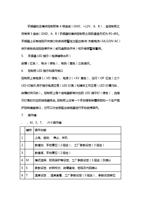
手操器和主模块控制板有4根连线(GND、+12V、A、B),各控制板之间有根3连线(GND、A、B)手操器和模块控制板之间的通信方式为RS-485。
手操器上设有线控开关接口和系统报警独立输出接点(负载电流>5A/220V AC)供外接系统远控启停开关(或风盘联动开关)和外接报警装置用。
5. 手操器LED指示(电源键导光环)故障(红色)、制冷(绿色)、制热(黄色)三色指示。
6. 控制板LED指示和操作接口控制板上有电源1(VD 绿色)、电源2(+5V 黄色)、运行(OP 红色)三个LED灯指示,用于指示电源正常(LED灯亮)和模块工作正常(LED灯慢闪动,故障时快闪动)。
控制板上每个继电器都有对应的LED指示灯(绿色),当指示灯亮时对应的继电器吸合。
控制板上设有一个手动强制除霜按钮和一个生产维护控制键盘接口,它可以对全部输出继电器进行手动启停操作。
7. 操作键、、M、S、T、六个操作键8.操作说明8.1 开机长按(3s)电源键开机,LCD显示产品数列号(缺省值为00 00),系统进入待机状态,LCD常显示系统回水温度,水泵启动。
8.2 工作模式选择按M键进行‘制冷’→‘制热’→‘自动’循环选择,短按电源键确认,对应工作模式的指示符号闪动,延时3min后根据设定的温度条件开始启动相应设备,LCD 显示已被启动的设备指示符号。
8.3 温度设定(回水温度)设定工作模式后,按T键进入确定模式下的控制温度,LCD显示原设定温度值并闪动,用∧/∨键修改温度值,按T键退出。
8.4 查看温度长按T键LCD显示模块代号(如SYS A),短按T键进入温度查询状态,用∧/∨键查看1~8个温度;按T键退出或者延时约30s后自动退出(下同)。
8.5 故障保护查看长按S键进入故障查看,如有保护故障出现,LCD显示警钟、模块代码和各模块的故障保护代号:flow (水流)、1(1#压缩机高压)、2(1#压缩机低压)、3(1#压缩机过载)、4(1#冷凝风机过载)、5(2#压缩机高压)、6(2#压缩机低压)、7(2#压缩机过载)、8(2#冷凝风机过载);温度传感器故障时LCD显示模块代号、警钟和温度符号,故障传感器的温度显示为空,可参照8.4查看各路温度的状态。
三菱重工海尔集控系统操作流程

集控系统操作流程一、登入系统1)点击谷歌浏览器2)在地址栏中输入“192.168.1.10”;3) 用户名为“Admin”,密码默认为“123456”二、内机监控详解:1. 图中所标注的“1”建筑和区域所形成的层级树。
2. 图中所标注的“2”显示“当前页”的内机的个数和选中的数量。
3. 图中所标注的“3”批量设定选中内机的参数。
(点击后会弹出批量控制页面)4. 图中所标注的“4”是否选中“当前页的所有机组”。
5. 图中所标注的“5”选择的建筑或者区块名称。
6. 图中所标注的“6”机组显示的模块。
7. 图中所标注的“7”是否选中一个对应的机组。
8. 图中所标注的“8”当前建筑或者当前节点的页码控制。
9. 图中所标注的“9”内机的显示状态和是否有故障提示。
表示冷房模式 表示自动模式 表示送风模式 表示除湿模式表示暖房模式 表示通信异常 表示出现故障三、批量设定内机,需执行以下步骤:1.选择需要设定的机组,选择全选选中或者取消选中当前页面的所有机组。
2.选择“开关控制”。
3.选择“运转模式” 。
4.选择“风速设定”。
5.填写“温度设定”。
6.选择“摆叶位置”。
7.选择“控制模式”。
8.选择“滤网复位”。
9.选择“定期点检”。
10.选择“禁止线控”。
11.点击“确定”按钮执行,点击“取消”按钮取消。
✧若在批量设定页面中输入错误的信息,当点击确定按钮的时候,系统会有对应的错误提示。
✧当设定成功之后,并且页面会变成灰色,页面中出现的旋转的圆圈表示命令正在执行。
执行完毕后,页面右下角会弹出“设定成功”的提示框。
四、单台或批量设定内机,需执行以下步骤:1. 选中需要设定的内机。
(勾选内机名称前面的复选框,可单选或多选)2. 点击“批量设定选中内机参数”按钮。
3. 选择“开关控制”。
4. 选择“运转模式”。
5. 选择“风速设定”。
6. 填写“温度设定”。
7. 选择摆叶位置。
8. 选择“控制模式”。
9. 选择“滤网复位”。
螺杆冷水机组维修调试手册

安装调试和维护手册青岛海尔空调电子有限公司2004年6月目录机组简介第一章机组安装1.1货运及存放1.2机组安装前期准备1.3机组的吊运及定位1.4管道连接1.5 现场冷媒充注1.6电气连接第二章机组运转2. 1机组运转前的检查项目2.2机组运行2. 3机组运行控制2. 4运行管理和停机注意事项第三章机组维护保养和故障处理3.1概述3.2维护3.3水质管理3.4故障处理初次安装调试海尔水冷冷水螺杆机组之前,操作施工人员应当完全熟悉机组操作说明和其他必要的工作资料,并仔细阅读本手册内容。
了解相应的安装、调试、维护注意事项及相关要求,保证安装规范,使机组运行于最佳状态。
机组简介:水冷半封螺杆型冷水机组是一种以水为冷却介质的中央空调产品,和相同冷量的风冷机组相比,由于其冷凝器和蒸发器均采用特制高效传热管制作,因此结构紧凑,体积小,效率高;又由于没有冷凝风机,因而噪声低。
本公司在水冷半封螺杆型冷水机组制造方面有着成熟的技术,完善的工艺和先进的检测设备,再加上精选的国际一流配件,保证了机组的稳定、高效运行。
海尔水冷半封闭螺杆型冷水机组既能为宾馆、医院、药厂、影剧院、体育馆、娱乐中心、商业大厦、工矿企业等场所的中央空调系统提供冷水,也可为纺织、化工、食品、电子、科研等部门提供工艺冷冻水。
1.机组铭牌——位于机组控制箱的左侧。
2.系统部件——包括蒸发器,冷凝器,压缩机,节流装置,控制系统等。
3.型号命名法:LS B LGHX由于设备内部的相对压力、电器元件、以及安装位置等因素,操作时一定要注意安全,要先看清楚有关说明书,及各种标签上所列的安全注意事项。
第一章 机组安装 1.1货运及存放1.1.1发货 海尔水冷半封闭螺杆式冷水机组一般在工厂组装为一个整体,即由工厂加工装配、配管布线、氦检漏试验、充注制冷剂、进行性能测试、保温并经过全过程注意:本手册所介绍的知识并不意味读过本手册任何人可承担安装、调试、操作和维护中的任何一项工作。
螺杆冷水机组维修调试参考手册教材

安装调试与维护手册青岛海尔空调电子有限公司2004年6月目录机组简介第一章机组安装1.1货运及存放1.2机组安装前期准备1.3机组的吊运及定位1.4管道连接1.5 现场冷媒充注1.6电气连接第二章机组运转2. 1机组运转前的检查项目2.2机组运行2. 3机组运行控制2. 4运行管理和停机注意事项第三章机组维护保养与故障处理3.1概述3.2维护3.3水质管理3.4故障处理初次安装调试海尔水冷冷水螺杆机组之前,操作施工人员应当完全熟悉机组操作说明和其他必要的工作资料,并仔细阅读本手册内容。
了解相应的安装、调试、维护注意事项及相关要求,保证安装规范,使机组运行于最佳状态。
机组简介:水冷半封螺杆型冷水机组是一种以水为冷却介质的中央空调产品,与相同冷量的风冷机组相比,由于其冷凝器和蒸发器均采用特制高效传热管制作,因此结构紧凑,体积小,效率高;又由于没有冷凝风机,因而噪声低。
本公司在水冷半封螺杆型冷水机组制造方面有着成熟的技术,完善的工艺和先进的检测设备,再加上精选的国际一流配件,保证了机组的稳定、高效运行。
海尔水冷半封闭螺杆型冷水机组既能为宾馆、医院、药厂、影剧院、体育馆、娱乐中心、商业大厦、工矿企业等场所的中央空调系统提供冷水,也可为纺织、化工、食品、电子、科研等部门提供工艺冷冻水。
1. 机组铭牌——位于机组控制箱的左侧。
2. 系统部件——包括蒸发器,冷凝器,压缩机,节流装置,控制系统等。
3. 型号命名法:1.1货运及存放1.1.1发货海尔水冷半封闭螺杆式冷水机组一般在工厂组装为一个整体,即由工厂加工装配、配管布线、氦检漏试验、充注制冷剂、进行性能测试、保温并经过全过程的质量检验后完成合格产品的制造。
1.1.2交货机组由本公司负责运输到工程工地,当物流公司将机组运到用户现场时,销售人员协调当地经销商和用户负责卸货,对机组进行检查办理签收事项。
当场对照机组的铭牌、装箱清单上所列的随机附件、随机证件等项目进行检查。
三菱重工空调使用说明书
● Display brightness can be adjusted, follow procedure on !. Require Wireless LAN connecting adapter which available as accessory.
2 PREPARATION BEFORE USE
disconnect the power supply or turn off the breaker. • This appliance can be used by children aged from 8 years and above and persons
with reduced physical, sensory or mental capabilities or lack of experience and knowledge if they have been given supervision or instruction concerning use of the appliance in a safe way and understand the hazards involved. Children shall not play with the appliance. Cleaning and user maintenance shall not be made by children without supervision. • This appliance is not intended for use by persons (including children) with reduced physical, sensory or mental capabilities, or lack of experience and knowledge, unless they have been given supervision or instruction concerning use of the appliance by a person responsible for their safety. • Children should be supervised to ensure that they do not play with the appliance. • Do not use any refrigerant different from the one specified for complement or replacement. Otherwise, abnormally high pressure may be generated in the refrigeration cycle, which may result in a failure or explosion of the product or an injury to your body.
海尔冷水机组调试维护手册(风冷模块)
冷水机组调试维护手册(风冷模块)青岛海尔空调电子有限公司2003年10月目录机组介绍............................................ ........... . (3)电控箱示意图..................................................... .4机组调试工具准备............................................ .. .5调试前检查............................................ ........ . (5)…………………………………….. …….. …. . 5机组检查............................................ ........ . (6)水系统检查............................................ ........ . (7)电系统检查调试过程............................................ ........... .. (7)............................................ ........ . (7)水系统调试......................................... (8)收操器、信号线连线............................................ ........... (8)水泵调试............................................ (9)靶式流量开关调试正式开机调试............................................ . (10)............................................ ........... (10)准备工作…………………………………….. ……….. . ..11开机步骤…………………………………….. ……….. . ..12观察记录............................................ ....... (12)室内末端调试故障问题分析处理............................................ . (13)维护保养............................................ ........... . (14)机组简介:海尔风冷模块式冷(热)水机组是我公司为宾馆、医院、影剧院、体育馆、娱乐中心、商业大厦、写字楼、工矿企业等场所开发设计的中央空调产品,它可安装于屋顶或室外庭院,不需专用机房和冷却塔。
三菱重工空调说明书
操作說明書空調器2-19在操作空調器前,請細讀此操作說明,並保存此書以備日後參考。
安裝前,安裝人員應:閱讀安裝說明,並要求顧客保留此安裝説明以備將來參考。
取出包裝在室内機箱子的遙控器。
如果將本空調器轉讓給新的用戶或送往回收廠,請務必將本説明書一并交出。
Operating Instructions Air Conditioner20-37Before operating the unit, please read these operating instructions thoroughly and keep them for future reference.Before installation, the installer should:Read the Installation Instructions, then request the customer keep them for future reference.Remove the remote control packed with the indoor unit.If the equipment is transferred to a new user or delivered to a recycling plant, be sure also to hand over the manual.Model No.Indoor UnitOutdoor UnitRS-YU9ZK RS-YU12ZK RU-YU9ZK RU-YU12ZKOperating InstructionsAir ConditionerACXF55-338902簡易指南提供快速的製冷和最高的舒適感。
請在室內機遙控接收器的 8 米範圍内使用遙控器。
裝入電池3211拉出遙控器的背蓋。
2裝入 AAA 或 R03 電池。
3把蓋關上。
A 時間設定1按下 ,然後按下並設置時間。
海尔冷水机组调试维护手册 风冷模块
冷水机组调试维护手册(风冷模块)青岛海尔空调电子有限公司2003年10月目录机组介绍............................................ ........... . (3)电控箱示意图..................................................... .4机组调试工具准备............................................ .. .5调试前检查............................................ ........ . (5)…………………………………….. …….. …. . 5机组检查............................................ ........ . (6)水系统检查............................................ ........ . (7)电系统检查调试过程............................................ ........... .. (7)............................................ ........ . (7)水系统调试......................................... (8)收操器、信号线连线............................................ ........... (8)水泵调试............................................ (9)靶式流量开关调试正式开机调试............................................ . (10)............................................ ........... (10)准备工作…………………………………….. ……….. . ..11开机步骤…………………………………….. ……….. . ..12观察记录............................................ ....... (12)室内末端调试故障问题分析处理............................................ . (13)维护保养............................................ ........... . (14)机组简介:海尔风冷模块式冷(热)水机组是我公司为宾馆、医院、影剧院、体育馆、娱乐中心、商业大厦、写字楼、工矿企业等场所开发设计的中央空调产品,它可安装于屋顶或室外庭院,不需专用机房和冷却塔。
三菱重工海尔控制面板说明书
三菱重工海尔控制面板说明书
三菱重工海尔控制面板说明书是一份用于指导用户正确使用该
控制面板的重要文档。
本说明书旨在提供简明扼要的操作指南,帮助用户充分了解控制面板的功能和使用方法,以确保安全、高效地操作。
1.控制面板概述
本章节将介绍控制面板的外观和基本功能,包括各个按钮、指示灯的作用,以及控制面板上的显示屏和触摸功能等。
2.控制面板安装与连接
本章节将详细介绍如何正确安装控制面板,并连接到相应的设备。
提供了安装步骤、连接方法和注意事项等内容。
3.控制面板操作
本章节将逐一介绍控制面板上各个功能按钮的使用方法和操作
步骤。
涵盖了开关机、调节温度、设定定时器、选择模式等常用操作。
4.高级功能设置
本章节将介绍一些更高级的功能设置,如语言选择、音量调节、屏幕亮度调节等。
并提供了相应的操作指引和注意事项。
5.故障排除与维护
本章节将列举一些常见问题和解决方法,帮助用户在遇到故障时能够快速排除问题。
同时,提供了控制面板的维护方法和注意事项。
6.安全注意事项
本章节将重点强调用户在使用控制面板时需要注意的安全事项,包括使用环境要求、电源接线要求、防护措施等内容。
- 1、下载文档前请自行甄别文档内容的完整性,平台不提供额外的编辑、内容补充、找答案等附加服务。
- 2、"仅部分预览"的文档,不可在线预览部分如存在完整性等问题,可反馈申请退款(可完整预览的文档不适用该条件!)。
- 3、如文档侵犯您的权益,请联系客服反馈,我们会尽快为您处理(人工客服工作时间:9:00-18:30)。
内部资料注意保密
协议调试手册
(海尔空调三菱重工)
中兴通讯股份有限公司
版权所有,保留一切权利。
版权所有,侵权必究。
Copyright (C) 1997 by ZTE Co. Ltd..
All rights reserved.
设备说明
设备接口描述
(尽可能提供设备和接口图片,不同型号设备存在差别)
(如何判断有无接口板、接口板外观描述)
(接口类型、定义)
RS485电平;RS485方式 --> 白线+ 、黑线- 。
(波特率、数据位、校验位、停止位)
波特率9600、数据位8位、偶校验、起始/停止位1位
(操作步骤、拨码设置等)
监控接口板为独立安装在一个方形铁盒内。
地址拨码为SW1、SW2,SW1为十位数(取值范围为0,1,2,3,4),SW2为个位数(取值范围为0-9)。
将SW3-1设置为ON,可在没有遥控器情况下,只通过监控板控制空调。
指示灯红色LED G:表示接口板与空调通讯状态。
闪烁表示通讯正常;指示灯绿色LED R:表示通讯异常指示。
(特殊说明)
该接口板适用于海尔三菱重工8型机。
包括:RF75WD、RFD75WD、LF75WD、RF13WD、RFD13WD、LF13WD、RF73WDT、RFD73WDT、LF73WDT、RF25WD、RFD25WD、LF25WD、
RFU75WD、RFU13WD、RFU25WD。
调试方法
pcudebug.exe
发送:
接收:
(通讯是否存在时限要求、是否存在控制条件等)
通道表(包括物理通道和逻辑通道)
---AI通道---
AI通道17(双字节64) = 空调回风温度
---AO通道---
AO通道16(双字节503) = 空调温度设置点
---DI通道---
DI通道16(双字节3000) = 监控模块故障
DI通道18(双字节193) = 空调开关机状态(0-关机,1-开机)
DI通道19(双字节202) = 空调自动状态(0-否,1-是)
DI通道20(双字节197) = 空调除湿状态(0-否,1-是)
DI通道21(双字节195) = 空调制冷状态(0-否,1-是)
DI通道22(双字节200) = 空调送风状态(0-否,1-是)
DI通道23(双字节194) = 空调加热状态(0-否,1-是)
DI通道24(双字节204) = 弱风风量状态(0-否,1-是)
DI通道25(双字节203) = 急风风量状态(0-否,1-是)
DI通道26(双字节425) = 遥控器通信异常(0-否,1-是) DI通道27(双字节244) = 热传感器断线(0-否,1-是)
DI通道28(双字节426) = 吸入传感器断线(0-否,1-是) DI通道29(双字节333) = 暖房高压异常(0-否,1-是)
DI通道30(双字节427) = 开关异常(0-否,1-是)
DI通道31(双字节428) = 电压过低(0-否,1-是)
---DO通道---
DO通道162(双字节551) = 空调开机
DO通道163(双字节552) = 空调关机
DO通道164(双字节561) = 自动运行
DO通道165(双字节563) = 空调除湿
DO通道166(双字节560) = 空调制冷
DO通道167(双字节562) = 空调送风
DO通道168(双字节559) = 空调制热
DO通道169(双字节670) = 弱风风量
DO通道170(双字节669) = 急风风量
DO通道171(双字节553) = 异常复位
关键及特殊数据
(特殊接收函数处理)
常见故障
(被监控设备监控功能是否可靠)。