modbus CANopen通信适配器应用指南和配置手册MCC-425
施耐德电气-NRX系列-Modbus通信适配器模块-操作手册说明书

UL1066/ANSI, UL489 系列NRX NF 壳架IEC IZMX16/新一代IZM91IEC 新一代IZM9UL489 系列 NRX RF 壳架IEC IZMX40警告(1) 只有具备资格的电气工作人员方可操作本设备。
(2) 如断路器不能被搬移至安全的工作地点,则务必始终断开一次和二次回路电源。
(3) 抽出式断路器应摇出至断开位置。
(4) 所有断路器均应切换至关闭位置,机构弹簧释能。
如不能遵守本操作说明书规定的这些步骤,则可能导致人员死亡、人身伤害、或财产损坏。
ƽ 警告应遵守本操作说明书及产品标签上规定的操作说明。
请注意以下五点安全规则:– 断电;– 确保装置不能意外重启;– 确保与电源隔离;– 接地及短路;– 遮盖或为临近带电部件提供屏障断开设备电源。
在设备维修期间,仅可使用正规渠道获得的备件。
在维修和更换时,必须严格遵守规定的维修间隔及说明,以避免人身伤害及开关板损坏。
本手册适用于:带PXR 脱扣器的IZM9/IZMX 系列 - Modbus 通信适配器模块(MCAM)的操作说明20189第1章:介绍N RX系列Modbus通信适配器模块(MCAM)(图1)是作为通信装置与兼容的NRX系列脱扣器/断路器在主通信网络运行(图2)的一种附件。
Modbus适配器采用Modbus RTU(远程终端单元)协议在Modbus 网络上与主机通信。
使用指定寄存器,信息通过MCAM在Modbus主机与PXR脱扣器之间交换。
图1. NRX系列Modbus通信适配器模块图2. Modbus网络中的通信适配器模块Modbus通信适配器模块是从机,因此需要主机触发控制命令。
每个Modbus 通信适配器模块都具有:• 断路器分闸/合闸/复位控制;• L ED状态指示灯,处于闪烁状态时显示模块带电;• Modbus 通信启用/禁用选择跳线,用于远距离分闸/合闸控制;• DIN导轨安装(11mm高、28mm宽、DIN 导轨最低要求);• 模块用24Vdc输入电源Modbus 通信适配器模块经过专门设计,可由经过充分训练的人员安装、操作及维护。
CanOpen通信卡说明书

10P-0007 CanOpenCommunication CardTo be used with AC10P Series InverterProduct ManualIssue 12016 Parker Hannifin Manufacturing Ltd.All rights strictly reserved. No part of this document may be stored in a retrieval system, or transmitted in any form or by any means to persons not employed by a Parker SSD Drives company without written permission from Parker Automation Wuxi, a division of Parker Hannifin Ltd . Although every effort has been taken to ensure the accuracy of this document it may be necessary, without notice, to make amendments or correct omissions. Parker Automation Wuxi cannot accept responsibility for damage, injury, or expenses resulting therefrom.WARRANTYRefer to Parker Hannifin Manufacturing Limited Terms and Conditions of Sale. These documents are available on request at /ADC. Parker Hannifin Manufacturing Limited reserves the right to change the content and product specification without notice.CANOPEN INSTRUCTION (1)I.INTRODUCTION (3)1.1.CAN OPEN (3)1.2.I NSTALLA TION (3)1.3.DB15INTERFACE PINS (3)1.4.CAN–BUS CONNECTION (4)1.5.H ARDWARE LAYOUT (5)1.6.LED INDICA TOR (5)1.7.S WITCH CODE (5)1.8.I NTERFACE (6)II.OPERATION GUIDE (6)2.1B AUD RA TE (6)2.2A DDRESS AND BAUD RA TE SETTING (6)2.3P ARAMETERS SETTING (7)2.4P ROTOCOL (7)2.5NMT CONTROL DEMAND (8)2.6N ODE PROTECTION FUNCTION (8)2.7S ERVICE DATA OBJECT (SDO) (8)2.7.1 Demand format of master station reading slave station (9)2.7.2 Node response when master station reads command (9)2.7.3 Command format of master station writing parameters (11)2.7.4 Slave response after master writes data (11)2.8PDO (13)2.8.1 Node edits object dictionary (14)2.8.2 TPDO communication parameters’ definition in the object dictionary (14)III.OPTIONAL MODE (15)3.1P ROFILE V ELOCITY M ODE (15)3.1.1 ControlWord (15)3.1.2 StatusWord (15)3.1.3 Parameters of rest speed mode (16)I.Introduction1.1.CANopenCANopen is a high layer protocol which bases on CAN serial bus system and CAL(CAN application layer). The communication card is used to connect inverter to CAN network.1.2.InstallationCommunication cableFig 2-1 CANopen card installation1.3.DB15interface pinsFig 2-2 interface pins1.4.CAN –bus connection1.5.Hardware layoutFig 2-2 CANopen bus card 1.6.LED indicatorColorGreenGreenGreenRed1.7.Switch code1.8.InterfaceII.Operation guide2.1Baud rate1Mbit/s 500kbit/s25m 100m2.2Address and baud rate setting16 bits switch code of SW4 and SW5 are used to set baud rate and communication device2.3Parameters setting2.4ProtocolIn CAN network, communication objects are used to transfer data. Periodic data object uses PDO to transfer real time data (control command, given value and status information). Service data object uses SDO to transfer non-real time data (parameters). The COB-ID related to variable data is as below:NMT object: 0x000;RPDO object: 0x200+NODE-IDTPDO object: 0x180+NODE-IDTSDO object: 0x600+NODE-IDRSDO object: 0x580+NODE-IDSYNC object: 0x0802.5NMT control demandNMT control demand is sent from master station, slave station does not need to reply. The format of NMT is as below:2.6Node protection functionNMT main node can check the current state of each node by node protection service.NMT-Master node sends remote frame (no data) is as below:NMT-Slave node sends the below messageThe data includes a trigger bit (bit7), trigger bit must be set to “0” or “1 alternately when node protection response. Trigger bit must be set to “0” when node protection request. Bit 0 ~ bit 6 means2.7Service data object (SDO)SDO can visit the item in the dictionary of device object. SDO can send any length data (when the data is more than 4 bytes, it should be divided into several messages). Master node will read or write slave node object dictionary by SDO communication, to set slave node parameters, download program, define communication type and data format of PDO.2.7.1 Demand format of master station reading slave station2.7.2Node response when master station reads commandif it reads successfully, node 2 returns to the below contents:Table 3-1 Command format of node responseNote: d0,d1,d2 and d3 are the data which need to be transferred.For example, if node 2 returns to 582 4F 00 60 01 FD 00 00 00, which meaning is as below:5824F00 6001 FD 00 00 00Transfer dataSub-indexIndex1 byteRead SDONode No.Send SDOThe index of node 1 reading from node 2 object dictionary is 0x6000, the sub-index is 0x01. It is FD 00 00 00.if read failed, node 2 returns to failed information.The format is as below:Note: SDO abort code error will return to related parameters according to different error. Please refer to Appendix 1.2.7.3 Command format of master station writing parametersThe format of master writing data is as below tableFor example, node 1 will transfer 603 2F 00 70 01 FD 00 00 00 , the meaning is as blow: 6032F00 7001 FD 00 00 00Transfer dataSub-indexIndex1 byteRead SDONode No.Send SDONode 1 will write the data FD 00 00 00 to the entry of node 3 object dictionary, which index is 7000h, and sub-index is 01h.2.7.4 Slave response after master writes dataif writing succeeds, node 3 will return writing success command to node 1. The format is as below:if writing failed, node will return to failed command, the format is as below:,Note: SDO abort code error will return to related parameters according to different error. Please refer to Appendix 1.Appendix 1 SDO abort code error2.8PDOPDO communication is mainly used to transmit real-time data which bases on the model of (Producer/Consumer). The data transmitted is limited within 1~8 bits.In the object dictionary, each PDO is described by two objects, PDO communication parameters and PDO mapping parameters.CANopen protocol defines four receivePDO (Receive-PDO), four sendPDO(Transmit-PDO).2.8.1 Node edits object dictionaryNote: 6040 01 10h means the data mapping to object dictionary, which index is 6040h, thesub-index is 00h and the length is 16bits.60ff 01 20h means the data mapping to object dictionary, which index is 60ffh, sub-index is 00h and length is 32bits.2.8.2 TPDO communication parameters’ definition in the object dictionaryNote: 6041 01 10h means the data mapping to object dictionary, which index is 6041h, thesub-index is 00h and the length is 16bits.606C00 20h means the data mapping to object dictionary, which index is 606Ch, sub-index is 00h and length is 32bits.III.Optional modeServo drive can realize various operational mode. Master station writes to 0x6060 to set operational mode. Slave station writes to 0x6061 to show actual operational mode.3.1 Profile Velocity Mode3.1.1 ControlWordControl word objectControlword instruction is as below:3.1.2 StatusWordStatsword instruction is as below:In speed mode, bit definition is as below:3.1.3 Parameters of rest speed mode1.Set operational mode (6060h) to 0x02;2.Set target velocity (6042) to “according to user demand”3.Set acceleration time (6046.02h) to “according to user demand”.4.Set deceleration time (6048.00h) to “according to user demand”5.Set Max of velocity (6046.00h) to “according to user demand”6.Set Min of velocity (6046.01h) to “according to user demand”.7.Set control word(6040h)to 0x0F ;er can read operational state by state word (6041h).er can read actual velocity by 6044h.。
CANopen使用手册(V1.00)

CANopen使⽤⼿册(V1.00)CAN open使⽤⼿册ProNet伺服驱动器ESTUN修订记录⽇期修订版本描述作者2009/4/25 1.00 初稿完成移振华2009/9/22 1.00 增加第8章移振华—— ⽬录 ——1、概述 (5)1.1 CAN 主要相关⽂档 (5)1.2 本⼿册使⽤的术语和缩语 (5)1.3 CANopen概述 (6)2、接线和连接 (7)3、CANopen通讯 (8)3.1 CAN标识符分配表 (9)3.2 服务数据对象SDO (10)3.3 过程数据对象PDO (12)3.3.1 PDO参数 (14)3.4 SYNC报⽂ (20)3.5 Emergency报⽂ (21)3.6 HEARTBEAT报⽂ (23)3.7⽹络管理(NMT) (24)4、单位换算单元(Factor Group) (26)4.1 单位换算相关参数 (27)4.1.1 position factor (27)4.1.2 velocity factor (29)4.1.3 acceleration factor (30)5、位置控制功能 (31)5.1 位置控制相关参数 (33)6、设备控制 (35)6.1 控制状态机 (35)6.2 设备控制相关参数 (36)6.2.1 controlword (37)6.2.2 statusword (38)6.2.3 shutdown_option_code (39)6.2.4 disable_operation_option_code (40)6.2.5 quick_stop_option_code (40)6.2.6 halt_option_code (41)6.2.7 fault_reaction_option_code (41)7、控制模式 (42)7.1 控制模式相关参数 (42)7.1.1 modes_of_operation (42)7.1.2 modes_of_operation_display (43)7.2 回零模式(HOMING MODE) (44)7.2.1 回零模式的控制字 (44)7.2.2 回零模式的状态字 (44)7.2.3 回零模式相关参数 (45)7.2.4 回零⽅法 (47)7.3 速度控制模式(PROFILE VELOCITY MODE) (49) 7.3.1速度模式的控制字 (49)7.3.2 速度模式的状态字 (49)7.3.3 速度控制模式相关参数 (49)7.4 位置控制模式(PROFILE POSITION MODE) (53) 7.4.1 位置模式的控制字 (53)7.4.2 位置模式的状态字 (53)7.4.3 位置控制相关参数 (54)7.4.4 功能描述 (56)8、CAN通讯相关参数 (58)附录对象字典表 (59)1、概述1.1 CAN 主要相关⽂档Document Name Source 3014.01: CiAVDSCiACANopen Communication Profilefor Industrial Systems - based on CALCiA DSP 402 V 2.0: CiACANopen Device Profile1.2 本⼿册使⽤的术语和缩语CAN控制器局域⽹CiA在⾃动化国际⽤户和制造商协会中的 CAN。
CANopen 采用多用途连接器(MCS) 说明书

Base module
Status indication
Electronics module
Marking area for
I/O identification Fieldbus connection
Fuse for
to external Sensors
CANopen
采用多用途连接器(MCS)I/O 模块;10 kbaud ... 1 Mbaud; 支持数字量信号
符合CANopen 标准的WAGO-I/O-SYSTEM 752 是WAGO 紧凑型现场总线节点中的一员用于分布式的自动化控制系统该产品具有固定数量的数字量输入点(DI) 及数字量输出点(DO) 并通过CANopen 总线将信号传送至一个管理控制器各种具有不同I/O 数量组合的节点可供使用
一个现场总线节点的组成G 基板
G 可插入式电子模块
在基板上可以预先完成对现场总线的配线以及与传感器/执行器连接的配线电子模块含电子线路并可直接插入到基板上电子模块可以在不影响现场配线的情况下进行更换
电子模块的电源端子以及连接传感器执行器的现场接线端子均采用WAGO 笼式弹簧连接技术执行器电源端子各自为8个数字量输出回路供电以建立安全回路传感器电源通过一个熔断器保护注意需要使用EDS 文件
Sensor supply output driver supply Fieldbus connection
Fieldbus connection
DI (1…16)DO (1…16)。
关于CANopen通讯模块的使用方法
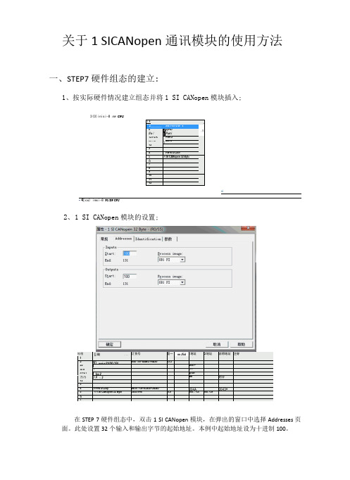
关于1 SICANopen通讯模块的使用方法一、STEP7硬件组态的建立:1、按实际硬件情况建立组态并将1 SI CANopen模块插入;3(0)inisi-8 nm CPU「1A2 ________ ms 1-8 P9/W "VIl n /irIFpjr-iDPert i,三12 P2 K Fort 2X1 P3\Are 31234PM-E DC24V5| 1 SI CANopen 32 Byt<6789101112ni- 4| co) imsi-8 PS/DP CPU怖稽[j 酸...订货号固一nn Jfiid i地址Q地址诊得地址注穿12即msi-s P9/DP CFV6IS7 151-GABO1-0A90Y3 22212047^Xi n *I*/冢如Il P2 l 1 foe 22(X5/力乃J P。
八3aw*的分1234y PH-E DC24y BEST 138-4CAOI-OAAO204A2043*5 1 1 SI CAKopon 32 Byte020570-B VI.0100. . 13!100. 13167在STEP 7硬件组态中,双击1 SI CANopen模块,在弹出的窗口中选择Addresses页面。
此处设置32个输入和输出字节的起始地址。
本例中起始地址设为十进制100。
2、1 SI CANopen模块的设置;在性-1 SI CANopen 32 Byte - (R0/S5)常规Addresses | Identification确定选择“参数”页面,设置“Baudrate”以及input/output data size,如上图所示。
PS:理论上Process data mode因为本次传输数据在32 Byte内,可选择Standard模式,但不知道为什么会报错,所以选择Fragmented模式。
双击STEP 7硬件组态中的CPU,选择“周期/时钟存储器”,修改过程映像输入/输出区的大小。
CANOpen编码器说明书

CANOpen编码器说明书1、CANopen介绍 (1)2、通信对象 (1)3、CANopen预定义连接集 (3)4、编码器 (5)4.1 编码器说明 (5)4.2 接线说明 (5)5、Object directory(对象字典) (7)5.1 Detailed description of the communication parameters(通讯子协议区域) (7)5.1.1 Object 1000h: Device type(设备类型) (7)5.1.2 Object 1001h: Error register(错误寄存器) (7)5.1.3 Object 1003h: Predefined error field(预定义错误区域) (7)5.1.4 Object 1005h: COB-ID for SYNC(SYNC标志符) (8)5.1.5 Object 1008h: Manufacturer device name(制造商设备名) (8)5.1.6 Object 1009h: Hardware version(硬件版本) (8)5.1.7 Object 100Ah: Software version(软件版本) (8)5.1.8 Object 100Ch und 100Dh: Guard Time and life time factor(节点保护参数) (8)5.1.9 Object 1010h: Save parameters(保存参数) (9)5.1.10 Object 1011h: restore default parameters(恢复默认参数值) (9)5.1.11 Object 1014h: COB-ID emergency messages(EMCY标志符) (9)5.1.12 Object 1017h: Producer Heartbeat Time(Heartbeat报文周期) (10)5.1.13 Object 1018h: Identity Object(设备ID) (10)5.1.14 Object 1800h: 1.transmit PDO parameter (TXPDO1 异步) (10)5.1.15 Object 1801h: 2.transmit PDO parameter (TXPDO2 同步) (10)5.2 Detailed Description of the Manufacturer(制造商特定子协议区域) (11)5.2.1 Object 2000h: Mode(工作模式) (11)5.2.2 Object 2001h: LocalAddress(编码器通讯地址) (12)5.2.3 Object 2002h: Max_LoopValue(循环测量时的最大值) (12)5.2.4 Object 2003h: Min_BackForthValue(往复测量时的最小值) (12)5.2.5 Object 2004h: Max_BackForthValue(往复测量时的最大值) (12)5.3 Detailed Description of the General Encoder Parameters(标准的设备子协议区域) (13)5.3.1 Object 6000h: Operating parameters(操作参数) (13)5.3.2 Object 6003h: Preset value(外部置位的设定值) (13)5.3.3 Object 6004h: Value of position(编码器当前位置值) (14)5.2.6 Object 6200h: Cyclic timer(发送测量值间隔时间) (14)5.3.4 Object 6500h: Operating status(操作状态) (14)5.3.5 Object 6501h: SingleTurn resolution(每圈对应的测量值) (14)5.3.6 Object 650Bh: Serial number(出厂序号) (14)6、RS232通讯参数 (15)7、Layer-Setting-Service (LSS) (16)附:CANopen报文分析 (18)1、CANopen介绍从OSI网络模型的角度来看同,现场总线网络一般只实现了第1层(物理层)、第2层(数据链路层)、第7层(应用层)。
CANopen协议应用指南

Protocol Layer Interactions
协议层交互
发送设备
CANopen Application
Layer
CAN Data Link Layer
CAN Physical Layer
Object at Index
ID + Data ... ID + data
CAN_L CAN_H CAN_L
Mini Style Connector
5-pin Mini Style Connector : ANSI/B93.55M-1981
male 3
female 3
4
22
4
5
11
5
If 5-pin Mini Style Connectors are used the following pinning applies:
Data Link Layer and High-Speed Transceiver (ISO 11898)
BBiti-t-TTimimininggaannddCCoonnnneecctotorrPPinin--AAssssigignnmmeenntt
bus lines
Ó CiA
CANopen通讯概念可以类似ISO Open Systems Interconnection (OSI) Reference Model描述. CANopen描述了一种标准化应用层和通讯协议。用于可编程设备的可选框架规定了额外的通讯功 能。
Open Style Connector
Open Style Connector
female
male 12345
123 4 5
If Open Style Connectors are used the following pinning is recommended:
Modscan使用说明
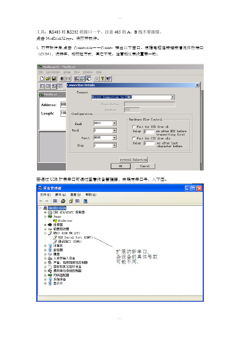
工具:RS485转RS232的接口一个。
注意485的A,B线不要接错。
点击ModScan32.exe。
将打开软件。
1, 打开软件后,点击Connection――Connec弹出以下窗口。
根据电脑连接链接情况修改端口(COM),波特率,和校验方式,其它不变。
注意和仪表设置要一致。
若通过USB扩展串口可通过查看设备管理器,来确定串口号,入下图。
2.
Device ld ――仪表地址(和仪表设置一致);
可通过仪表按键查看,若无显示可通过仪表序列号(10位数)的最后三位推断,最后三位不大于247,则为地址,大于则减去247,直至小于等于247.
MODBUS Point Type ――通讯命令(03,04均可);
Address ――起始地址;
Length ――读取的长度(可设为2)。
3.点击开始通讯,通讯若正常Valid Slave Responses的值将增加。
- 1、下载文档前请自行甄别文档内容的完整性,平台不提供额外的编辑、内容补充、找答案等附加服务。
- 2、"仅部分预览"的文档,不可在线预览部分如存在完整性等问题,可反馈申请退款(可完整预览的文档不适用该条件!)。
- 3、如文档侵犯您的权益,请联系客服反馈,我们会尽快为您处理(人工客服工作时间:9:00-18:30)。
Modbus / CANopen适配器MCC-425产品手册REV1.2上海泗博自动化技术有限公司SiboTech Automation Co., Ltd技术支持热线:021-5102 8348E-mail:support@- 2 -目 录1 产品概述...........................................................................................................................................................- 3 -1.1 产品功能................................................................................................................................................- 3 -1.2 产品特点................................................................................................................................................- 3 -1.3 技术指标................................................................................................................................................- 3 -1.4 电磁兼容性能........................................................................................................................................- 5 -1.5 相关产品................................................................................................................................................- 6 -1.6 术语解释................................................................................................................................................- 6 - 2 快速应用指南...................................................................................................................................................- 8 -2.1 硬件连接................................................................................................................................................- 8 -2.2 安装软件................................................................................................................................................- 8 -2.3 通讯调试................................................................................................................................................- 8 - 3 产品外观...........................................................................................................................................................- 9 -3.1 外观说明................................................................................................................................................- 9 -3.2 指示灯..................................................................................................................................................- 10 -3.3 CAN 端口接线.......................................................................................................................................- 10 -3.4 串口接线..............................................................................................................................................- 11 -3.5 数码管显示..........................................................................................................................................- 11 -3.6 按键......................................................................................................................................................- 12 - 4 软件配置.........................................................................................................................................................- 13 -4.1 配置前注意事项..................................................................................................................................- 13 -4.2 用户界面..............................................................................................................................................- 15 -4.3 设备视图操作......................................................................................................................................- 16 -4.4 配置视图操作......................................................................................................................................- 19 -4.5 硬件通讯..............................................................................................................................................- 25 -4.6 加载和保存配置..................................................................................................................................- 26 -4.7 自动映射..............................................................................................................................................- 27 -4.8 EXCEL 文档输出..................................................................................................................................- 27 - 5 工作原理.........................................................................................................................................................- 29 - 6 疑难解答.........................................................................................................................................................- 33 - 7 应用案例.........................................................................................................................................................- 34 - 8 安装.................................................................................................................................................................- 35 -8.1 机械尺寸..............................................................................................................................................- 35 -8.2 安装方法..............................................................................................................................................- 35 - 9 运行维护及注意事项.....................................................................................................................................- 37 - 10 版权信息.......................................................................................................................................................- 38 - 附录A: CANopen 协议简介................................................................................................................................- 39 -- 3 -1 产品概述1.1 产品功能MCC-425是Modbus 主站协议与CANopen 从站协议转换的通信网关,可以实现单个Modbus 从站设备与CANopen 主站之间的数据通信。