磁共振(磁谐振耦合)无线充电技术鼻祖级文章-英文原文
新能源汽车电磁感应无线充电技术的研究
磁耦合谐振式技术是众多无线电能传输技术中的一种,它包括磁耦合感应式无线电能传输、磁耦合 谐振式无线电能传输和磁耦合双模无线电能传输。
磁耦合谐振式技术的理论是耦合模式。首先在发射侧电源变换电路依次由 380 V 交流电整流、斩波 和逆变成高频交流电,再通过发射线圈形成电能传输磁场变成电磁场能量,最后经接收线圈作用后形成2. 常见的无ຫໍສະໝຸດ 充电技术2.1. 磁场共振式
磁场共振式是通过线圈进行能量耦合,通过电磁线圈产生的电流,实现电能的传递。无线充电的 关键设备是电力发送器和电力接收器,即感应线圈,其中包括大电流 FPC 线圈和及精密金属线圈,FPC 具有一致性好,柔性强等优点,而精密线圈则具有电器性能占优,设计简单的特点。电力发送器符合 WPC 标准的设备线圈有到 50%占空比谐振半桥的作用。电力接收器关键电路是用于接收电力初级线圈,将未 稳压的经过稳压调节电路,尤其是负责身份的认证和电源要求的所有通信。但由于所需线圈直径较大, 两端频率要求相同,又要防止相同频率电磁波进行干扰,在技术上仍存在极大困难。技术电路图如图 1。
优点:传输速度快,可有效解决兼容性。 缺点:过度依赖谐振腔功能,设备技术成本要求高;发射和接受装置须在 同轴或圆心偏差在一定个范围内,否则会导致传输效率低或失谐。 应用:电动车无线充电,手机无线充电。
优点:技术简单;电能利用高,成本低,节能环保;易操作,安全可靠; 电能转化效率高,技术应用成熟。 缺点:远距离传输会降低传输电能效率,只能在短距离的范围里传输;设 备体积大,充电范围和位置都要固定,金属感应接触器发热快。 应用:电磁炉,电动牙刷,手机,电动汽车等。
彭海洋 等
3. 电磁感应无线充电技术的设计原理
无线充电技术是一种新型的能量传输技术,该技术摆脱线路的限制,是的电器电源不用接触便可充 电,在安全性、可靠性、便捷灵活性显示出比传统接触式充电器具有更高的优势。如今,无线充电技术 已从梦想变成了现实,从科技研究转移到了实际的生活应用领域。
利用共振原理的无线供电技术(经典)
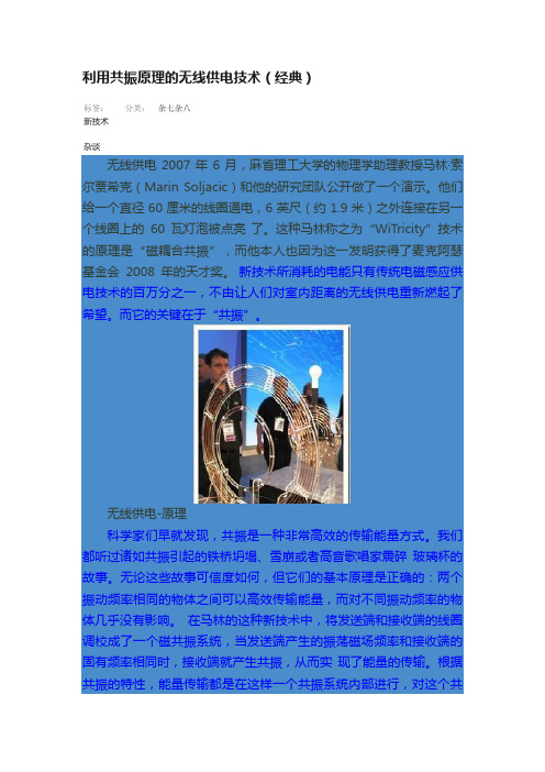
利用共振原理的无线供电技术(经典)标签:新技术杂谈分类:杂七杂八无线供电2007年6月,麻省理工大学的物理学助理教授马林·索尔贾希克(Marin Soljacic)和他的研究团队公开做了一个演示。
他们给一个直径60厘米的线圈通电,6英尺(约1.9米)之外连接在另一个线圈上的60瓦灯泡被点亮了。
这种马林称之为“WiTricity”技术的原理是“磁耦合共振”,而他本人也因为这一发明获得了麦克阿瑟基金会2008年的天才奖。
新技术所消耗的电能只有传统电磁感应供电技术的百万分之一,不由让人们对室内距离的无线供电重新燃起了希望。
而它的关键在于“共振”。
无线供电-原理科学家们早就发现,共振是一种非常高效的传输能量方式。
我们都听过诸如共振引起的铁桥坍塌、雪崩或者高音歌唱家震碎玻璃杯的故事。
无论这些故事可信度如何,但它们的基本原理是正确的:两个振动频率相同的物体之间可以高效传输能量,而对不同振动频率的物体几乎没有影响。
在马林的这种新技术中,将发送端和接收端的线圈调校成了一个磁共振系统,当发送端产生的振荡磁场频率和接收端的固有频率相同时,接收端就产生共振,从而实现了能量的传输。
根据共振的特性,能量传输都是在这样一个共振系统内部进行,对这个共振系统之外的物体不会产生什么影响。
这就像是几个厚度不同的玻璃杯不会因为同一频率的声音而同时炸碎一样(?)。
最妙的就是这一点了。
当发射端通电时,它并不会向外发射电磁波,而只是在周围形成一个非辐射的磁场。
这个磁场用来和接收端联络,激发接收端的共振,从而以很小的消耗为代价来传输能量。
在这项技术中,磁场的强度将不过和地球磁场强度相似,人们不用担心这种技术会对自己的身体和其他设备产生不良影响。
在2007年马林演示他的成果的时候,这项技术能够达到40%左右的效率。
这在某些场合是可以接受的,但是人们还想更进一步。
刚才我们提到的英特尔公司研究员们已经把传输效率提升到了75%,而马林小组最近声称,他们做到了90%。
电磁耦合共振式无线充电系统设计与实现

电磁耦合共振式无线充电系统设计与实现作者:韩竺秦江锦华来源:《电气传动自动化》2019年第01期摘要:本文利用电磁耦合共振技术实现手线充电技术方案,设计了无线充电器总体方案。
主要包括了发送端和接收端两部分,其中发射端电路使用NE555芯片产生占空比可调的高频PWM波来控制开关管驱动发射电感线圈,实现电能到磁能的转化;接收端则通过接收电感线圈将不断变化地磁信号转换为交流电信号,随后通过整流、滤波、稳压等处理,使电路末端输出为5.1V的直流电压进行无线充电。
同时在Multisim平台上搭建了电路模型并进行电路仿真,验证了其可行性。
对实际电路进行电路实验和分析,验证了该设计的正确性。
关键词:无线充电; 电磁耦合共振; 开关管中图分类号: TP273 ; ; ; ; ; ; ; ; ; ; ; ; ; ; 文献标识码: AAbstract: In order to realize the wireless charging technology,the thesis has taken electromagnetic c oupling resonant technology as the core wireless cell phone’s circuit structure. The design is consisted of transmitter and receiver. The transmitter generates adjustable duty cycle of PWM signal by NE555 chip to drive transmitter’s inductor by controlling MOSFET switch, so as to convert electric energy into magnetic energy. The receiver receives ever-changing magnetic signal and turn it into AC signal, and then processes it by rectifier, filter and regulator to output 5.1V voltage charging the cell phone. In the end of the thesis, it introduces how to set up the circuit model and to simulate it in the platform of Multisim,and it provides some analysis about the practical circuit’s experiment to proof the design is correct.Key words: wireless charging; electromagnetic coupling resonant; switch1 ;引言本文主要的研究內容是在通过学习和理解国内外与手机无线充电的相关课题和论文的基础上[1]-[4],自主设计一个简易的基于电磁耦合共振技术的手机无线充电器。
IDT基于磁感应和磁共振技术的无线充电解决方案

IDT基于磁感应和磁共振技术的无线充电解决方案对于消费类市场,磁感应(Magnetic Induction,简称MI)或磁共振(Magnetic Resonant,简称MR)都是备选方案。
无论消费市场朝哪个方向发展,一个已知的事实是,无线充电必将得到采用。
在手机提供商的主要推动下,无线充电将开始向手机生态系统市场渗透。
拥有强大生态系统的计算领域将紧随其后,使无线充电技术的采用进入下一个增长阶段。
之后,无线电源技术很有可能扩展到支持手机和计算解决方案的基础设施中。
未来的架构和解决方案中怎样运用无线电源技术,上述应用将仅仅是一个开端。
就磁感应技术而言,主要有两个流行标准:无线充电联盟(Wireless Power Consortium,简称WPC)和电源事务联盟(Power Matters Alliance,简称PMA)。
这两个标准都相当成熟,很多产品已经用在消费市场了。
无线电源联盟(Alliance for Wireless Power,简称A4WP)是第一个基于磁共振技术的标准。
这些标准和解决方案都引起了一些疑问,例如,无线电源技术将向哪个方向发展?采用哪些解决方案是最好的?移动设备便利性是促使消费移动解决方案最先采用无线技术的关键因素之一。
手机、平板电脑、媒体播放器、移动电视等不同的移动设备需要不同接口连接器的各种适配器,这意味着为了给移动设备充电,人们需要携带很多不同的连接器和适配器。
拥有强大的支持性基础设施和生态系统的通用无线适配器,可以解决这些需求。
在汽车、咖啡店、图书馆、餐馆、火车、飞机、办公室中提供无线充电,将满足人们所需的便利性。
图1:无线充电器系统:发送器和接收器方框图。
磁共振无线供电模块(witricity原理)
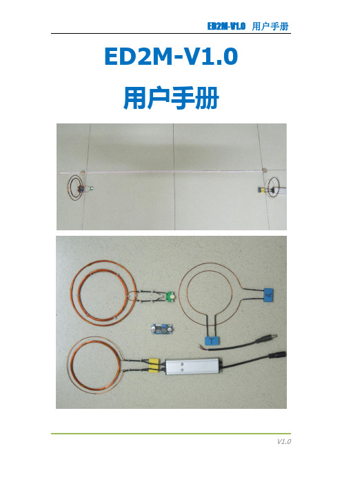
ED2M-V1.0 用户手册理论简介使用磁场的强耦合共振机制,我们实现了无辐射无线电力传输,小功率负载时传输距离达到了发射线圈半径的20倍!后续我们将进一步研究这种系统的实际应用和发展方向。
两个具有相同共振频率的共振物体能有效地交换能量,与此同时,非共振时则较少消耗能量。
在耦合共振系统(如声、电、磁、核)中,往往会有一个强耦合机制。
如果能在设计的系统中充分利用这种机制,能量转移预计将非常有效。
以这种方式进行的中距离能量传输几乎可以是全向的。
环境物体的干涉和能量损失均很小。
上述考虑适用于自然界各种共振现象。
在这里,我们采用了磁场共振。
由于大多数普通的材料不与磁场相互作用,磁场共振特别适合日常应用。
我们在兆级频率实现非辐射近场的磁耦合机制。
初看起来,这种能量转移使人想起了通常的磁感应,但是,请大家注意,通常的电磁感应在中距离应用中效率极低。
上述特定区域有效的中距离能量传输发生在强耦合共振时。
采用耦合模理论CMT 来描述这一物理系统,得到线性方程组如下:ED2M系统中核心部件为驱动模块-Driver,其功能为整个系统提供信号源,实现电能的转换并激励发射线圈A,以满足共振线圈阵列的要求。
为负载提供电能的Load由单铜环B和全波整流部分组成。
ED2M系统中另外四个组件——自共振线圈阵列,一个是源线圈阵列 S ,T,一个是受体线圈阵列 D ,R。
其中源线圈被恒定频率驱动,两个设备间具有耦合系数 k 。
能量被 D 接收后对负载做功。
源线圈阵列 S 通过电感耦合到信号发生电路;受体线圈通过电感耦合到负载。
自共振线圈阵列依靠调节S和T,D和R之间的距离达到共振。
系统工作示意图注: A 是半径6cm的单铜环,这是驱动电路的一部分。
该驱动电路,输出正弦波。
S 、T 和 D 、R 分别是独立的源和受体。
B 是带负载的铜环。
S 和 D 在一条线上。
硬件配置发射端发射端是整个系统的核心,包括驱动模块、发射线圈、源线圈阵列、电源插头;驱动模块外观尺寸:W*D*L=30.4*20.4*100mm;模块采用全密封形式,全面防水,可以达到较高的防护等级,以适应于多种应用场合。
基于磁耦合共振的无线充电系统研究

研究方法
本次演示的研究方法包括理论分析、数值计算和实验验证。首先,我们将建 立磁耦合谐振的数学模型,通过数值计算研究其传输效率和设备成本等因素的影 响。其次,我们将设计一个基于磁耦合谐振的电动汽车无线充电系统实验平台, 进行实验验证和分析。
研究结果
通过理论分析和数值计算,我们发现磁耦合谐振在电动汽车无线充电系统中 具有以下优势:
充电效率较低。而磁共振式充电是通过谐振来实现能量的传递,具有传输距 离远、充电效率高等优点,因此更适合于自主无线充电机器人的应用。
磁耦合谐振原理与设计
磁耦合谐振充电的基本原理是:在发射端和接收端设置相同频率的谐振器, 通过磁场的作用使两个谐振器产生共振,从而实现能量的传递。在设计中,需要 以下两个方面:
基于磁耦合共振的无线充电系 统研究
01 引言
目录
02 一、工作原理
03 二、系统构成
04 三、系统发展与优化
05 四、应用前景
06 参考内容
引言
随着科技的不断发展,无线充电技术已经成为我们日常生活中不可或缺的一 部分。传统的有线充电方式虽然已经能够满足大部分设备的需求,但其带来的种 种不便也日益凸显。在这种情况下,基于磁耦合共振的无线充电系统因其高效、 便捷和环保的特
此外,磁耦合谐振在电动汽车无线充电系统中的应用还具有便于维护、节能 环保等优点。然而,磁耦合谐振也存在一些局限性,如对位置和姿态的敏感性、 传输距离的限制等。
结论与展望
本次演示研究了基于磁耦合谐振的电动汽车无线充电系统,得出以下结论: 磁耦合谐振作为一种高效的传输技术,在电动汽车无线充电系统中具有很高的应 用价值,可以解决传统充电方式存在的问题。通过理论分析和数值计算,我们发 现磁耦合谐振在
传输效率、设备成本、安全性能等方面具有明显优势。磁耦合谐振也存在对 位置和姿态的敏感性和传输距离的限制等局限性,需要进一步研究和改进。
基于共振耦合的新能源汽车无线充电技术研究
基于共振耦合的新能源汽车无线充电技术研究新能源汽车作为当前热门的发展方向之一,其充电技术一直备受关注。
传统有线充电方式存在着充电效率低、使用不便等问题,而无线充电技术因其便捷性和安全性逐渐成为发展的趋势。
基于共振耦合的新能源汽车无线充电技术是目前研究的热点之一,本文将从理论基础、技术原理、应用现状以及未来发展等方面进行深入探讨。
首先,我们需要了解什么是基于共振耦合的无线充电技术。
基于共振耦合的无线充电技术是利用电磁场中的电磁感应耦合原理,通过两个磁共振器之间的耦合实现能量的传输。
其中,发射端的磁共振器负责产生电磁场,接收端的磁共振器则负责接收并将能量传递给电动车电池。
这种无线充电技术不仅具有高效、方便、快速的特点,还能减少人为操作中的电触点损耗和安全风险。
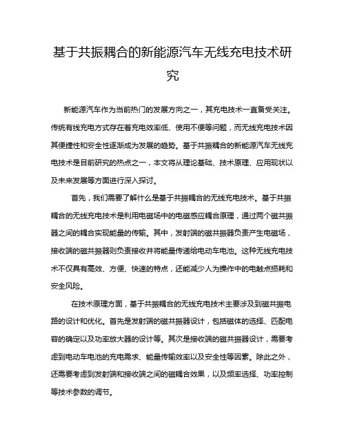
在技术原理方面,基于共振耦合的无线充电技术主要涉及到磁共振电路的设计和优化。
首先是发射端的磁共振器设计,包括磁体的选择、匹配电容的确定以及功率放大器的设计等。
其次是接收端的磁共振器设计,需要考虑到电动车电池的充电需求、能量传输效率以及安全性等因素。
除此之外,还需要考虑到发射端和接收端之间的磁耦合效果,以及频率选择、功率控制等技术参数的调节。
目前,基于共振耦合的新能源汽车无线充电技术在实际应用中取得了一定的进展。
许多汽车制造商和科研机构都在积极开展相关研究与实验,推动这项技术在新能源汽车行业的应用。
相对于传统有线充电方式,无线充电技术无需人工干预,只需停车在指定位置即可实现充电,大大提升了用户的使用便利性。
同时,无线充电技术还可以减少对道路和停车场的建设需求,节省了资源和空间。
然而,基于共振耦合的新能源汽车无线充电技术仍然存在一些挑战和问题。
首先是传输效率的提升和功率损耗的降低,当前技术中仍然存在能量传输效率低、热量损耗大等问题,需要进一步的研究和改进。
其次是系统的稳定性和安全性,由于无线充电技术涉及到高压、高频等复杂电磁场,存在一定的安全隐患,需要加强技术监测和控制。
磁耦合谐振式无线电能传输技术发展和应用研究

第28卷第1期2014年2月空军预警学院学报Journal of Air Force Early Warning Academy V ol.28No.1Feb.2014收稿日期:2014-01-06作者简介:朱忠尼(1957-),男,教授,主要从事电力电子与电力传动研究.磁耦合谐振式无线电能传输技术发展和应用研究朱忠尼,林洁,宋庆国,蔡轶(空军预警学院,武汉市430019)摘要:磁耦合谐振式无线电能传输技术是集合了电磁场、高频电力电子技术、电磁感应、电磁材料等多学科的应用技术,能安全、高效、灵活地实现电能的中距离传输.根据无线电能传输的类型及发展应用前景,指出磁耦合谐振式无线电能传输是最适合当前学科综合技术发展的一种具有广阔应用前景的新技术;归纳了当前磁耦合谐振式无线电能传输的发展水平和当前研究的热点问题;从提高传输效率、减小发射和接收线圈尺寸的角度出发,提出了电力电子技术面临的挑战和为适应高频化变频技术需要开展研究的问题.关键词:无线电能传输;磁耦合谐振;耦合模理论中图分类号:TM46;TM15文献标志码:A 文章编号:2095-5839(2014)01-0037-07无线电能传输技术是当前电工领域最活跃的热点研究问题之一,是集基础研究与应用研究为一体的前沿课题,也是当前国内外学术界与工业界积极探索的一个多学科强交叉的新的研究领域;它既是为了更加方便、灵活使用电能量的现实要求;也是一些特殊场合(如植入人体内的医疗设备、空间(天)应用的科学实验与军事设备)的迫切需求.无线电能传输(WPT)又称无接触式电能传输,是指电能从电源到负载的一种未经电气(线)直接接触的能量传输方式.无线能量传输技术一般可分为三类[1-2]:①应用电磁感应技术.通过改造和分离变压器技术,实现磁接触式短程(d <5cm)能量传输,目前中、小功率的电能传换技术已基本成熟[3-6].②以微波或激光形式,通过天线发射和天线接收方式实现能量的远程传输.其应用前景更加广泛,但目前技术不成熟[7],存在很多无法逾越的障碍,如电磁波在空间传输效率太低、方向性强、不能跨越障碍物等.③通过辐射电场或磁场耦合的电磁谐振方式实现中距离的电能传输.在目前的技术、半导体器件、电子材料条件下,最佳的传输距离为0.1~5m .它的优点在于方向性不敏感、传输效率高、能穿越非磁性物质[8].由于电场耦合存在安全隐患,一般很少考虑.重点是研究磁耦合谐振式无线电能传输技术.磁耦合谐振式无线电能传输(MCR-WPT)技术是利用谐振原理使其在中等距离(中等距离的定义为传输距离为天线直径的几倍至几十倍)有较高效率和较大功率的传输电能量[9].近年来,国内外学者相继开展了关于MCR-WPT 的理论和技术研究,取得了许多有积极意义的成果.文献[10-17]对MCR-WPT 技术的发展进行了详细的综合论述.文献[18-41]概括了近年来国外的部分成果,文献[42-47]则概括了国内部分最新研究成果.由于磁耦合谐振式无线电能传输机理复杂、技术难度大,涵盖了电磁场、电力电子技术、物理学、材料学、信息技术等诸多学科,还有许多理论和技术问题需要开展研究.本文从电力电子学科出发,介绍了目前关于MCR-WPT 的国内外研究水平及热点问题,探讨了有待解决的技术问题及发展趋势.1MCR-WPT 基本原理和目前的研究水平1.1MCR-WPT 系统1)基本结构目前MCR-WPT 系统大都采取如图1所示的结构[10]:两线圈结构和增加两匹配线圈形成的四线圈结构;图1(c)和(d)是它们的等效电路.能量传输系统包括电源端(能量发射端)和负载端(能量接收端)两部分.电源端包含导线绕制的并与电容并联的发射线圈和高频激励电源;接收端包括接收线圈与电容并联的谐振电路和负载电路.2)工作原理导线绕制的发射线圈为一空芯电感L ,L 与谐振电容并联构成谐振体,谐振体包含的能量在电场与磁场之间以其自谐振频率在空间自由振荡,产生以线圈为中心以空气为传输媒质的时变DOI:10.3969/j.issn.2095-5839.2014.01.010空军预警学院学报2014年磁场;与该谐振体相隔一定距离的接收端是由1个接收线圈并联1个电容形成的谐振体,其自然谐振频率与发射频率相同,所感应的磁场能同样在电场与磁场之间以其自谐振频率在空间自由振荡,同时两个谐振体之间不断地有磁场能交换,两谐振体内电场能与磁场能振荡交换的同时谐振体之间也存在着以相同频率振荡的能量交换,即两谐振体组成耦合谐振系统.发射线圈接收线圈(a)两线圈半实物结构发射线圈接收线圈电源线圈(b)四线圈半实物结构接收线圈L(c)两线圈等效电路ZL(d)四线圈等效电路图1MCR-WPT 系统结构及其等效电路3)能量传输准则无线能量传输准则必须遵循麦克斯韦方程中的全电流定律和电磁感应定律.根据全电流定律,发射线圈周围产生的磁场方程[48]为∇×H 1=J 1+∂D1∂t (1)式中,J 1为导线电流密度;∂D1为位移电流密度;H 1为磁场强度.根据电磁感应定律,接收线圈的感应电场方程为∇×Ε2=-μ0∂H12∂t (2)式中,E 2为接收线圈感应电场强度,H 12为源线圈与接收线圈耦合磁场,μ0为真空磁导率.同时,接收线圈需满足各向同性介质的本征方程J 2=γE 2(3)式中γ为绕制线圈导线的电导率.若系统没有负载消耗能量,发射线圈与接收线圈间耦合的能量为W 2=∫Α12J 2d V (4)式中,W 2为发射线圈与接收线圈谐振交替的场能;A 12为矢量磁位.发射线圈与接收线圈之间交替的无功功率为Q =ω1Mi 1i 2(5)式中,ω1为源线圈激励的磁场变化角频率,i 1、i 2分别为发射、接收线圈的电流,M 为源线圈与接收线圈之间的互感.由式(3)—式(5)可以看出:线圈中的磁场作用可以看作两线圈的互感抗.即整个系统可以表达为通过磁耦合谐振传输能量.1.2目前的研究水平MCR-WPT 研究水平主要通过传输功率、传输距离、传输效率和系统谐振频率体现.归纳文献[9]和[18-47]可以得到当前最好的研究水平,如表1所示.归纳表1中的参数,可以得到3点结论:①目前传输的功率较小:小于1kW ;②工作频率较宽:从几百千赫兹到几兆赫兹;③传输效率与传输距离成反比.表1MCR-WPT 目前的研究水平2研究的焦点问题MCR-WPT 作为一种中等距离无线电能传输技术,自从美国麻省理工学院2007年发表其研究成果[9]以来,就成为一个研究的热点.国内许多高校和科研院所在国家自然科技基金和863计划等项目的支持下,取得很多成果,但也产生了很多问题和疑惑,形成了当前研究的焦点.2.1系统模型目前,比较流行的系统模型是耦合模理论38第1期朱忠尼,等:磁耦合谐振式无线电能传输技术发展和应用研究和互感等效电路模型.1)耦合模理论麻省理工学院[49]最早将耦合模理论用于解释共振无线电能传输.以图1(a)的两线圈传输系统为例,可以得到电路的模式运动方程[50-51]:d a Fd t=-j(ωS-ΓF)a F+j ka Jd a J=-j(ωJ-jΓJ)a J+ka F üýþïï(6)式中,a F和a J为发射和接收谐振器的简正模幅值;ωF和ωJ为发射和接收谐振器频率;ΓF和ΓJ 为发射和接收谐振器损耗;k=k12=k21为两线圈的耦合系数;ωS为激励源频率.当ωF=ωJ=ωS=ω时,可以求得a F=A e jΔωt[cos(Ω0t/2)+ΓF-ΓJΩ0sin(Ω0t/2)]a J=A e jΔωt[2kΩ0sin(Ω0t/2)]üýþïï(7)式中,Δω=ω-(ΓF+ΓJ)/2,Ω0=(4k2-(ΓF-ΓJ)2)12,a F(0)=A为激励源幅值.由式(7)可以看出,当Ω0t/2=0时,a F(t)(模式1)被完全激发;当Ω0t/2=π/2时,a J(t)(模式2)被完全激发,接收能量;当Ω0t/2=π时,回归模式1.所以模式1与模式2之间的转换是完全的.当ωJ≠ωF时,也可求出式(6)的解,转换将是不完全的[52].2)互感等效电路模型基于互感去耦等效电路分析MCR-WPT模型是经典集总参数电路的分析法,等效电路方程为[53](Z S+R1+jωL1)i1-jωM12i2=u-j M21i1+(R2+jωL2+1jωC2+Z L)i2=0}(8)当ωJ=ωF=ω时,求解式(8)得到能量的传输效率为η=(ωu)2R LZ2[Z1Z2+(ωM)2]×100%(9)式中,M12=M21=M,Z1=(R21+(ωL1-11)2)12,Z2=((R1+R2)2+(ωL2-11)2)12.理论上讲,上述2种模型最终结果应是相等的,但在某种情况下,如发射端并联、接收端串联,2种理论的分析结果存在不一致性.因此,对MCR-WPT的系统模型还需要做更深入的研究.2.2频率分裂问题磁耦合无线电能传输时,经常会出现2个以上谐振频率或多个电流(压)峰值,即频率分裂问题[54-55].特别是在近距离传输时,多峰现象更为突出[56-57].频率分裂现象影响了传输效率[30],给系统参数检测带来困难,应给出合理的理论解释和频率控制策略.文献[24]等提出通过增加中继谐振线圈个数来抑制频率分裂现象,在很大程度上提高了传输效率[58],但增加了结构上的难度.文献[29]、[45]从耦合模模型研究出发,认为距离影响传输系统的相位,低于原谐振频率处,能量系统处于同相状态;高于原谐振频率处,传输系统处于反相状态,解释了谐振峰值数量的变化.为了抑制频率分裂现象,文献[26]、[32]、[57]在控制参数和结构上做了大量有成就的工作,如调整系统谐振频率、增加匹配网络等,并取得了一些较好的传输效果.2.3频率一致性磁耦合谐振式无线高效传输是建立在系统谐振频率一致的基础上的.保证在不同距离、不同工况下的频率一致性及频率一致性控制是非常重要的,否则系统的功率、传输效率及系统性能都会下降.为便于调整系统频率一致,文献[37]和文献[29]提出通过增加中继级线圈调节传输峰值.文献[29]提出利用电路理论分析带有中继谐振线圈的传输系统,通过求解系统矩阵的特征值,得到新的谐振频率ω,这些理论和方法还需要在今后的研究中进一步验证.2.4系统结构与传输路径系统结构与传输路径的研究主要包括线圈的对数、线圈的中心线对准、单发射—单接收、单发射—多接收和多发射—单接收等问题.目前国内外许多学者就系统结构与传输路径开展了多项研究.取得的相关成果有:①MCR-WPT 对发射端和接收端的方向指向不甚敏感[59-60];②采取一个发射线圈—多个接收线圈方式,总体传输效率高于一对一结构[29,61-64];③当接收线圈数目达到一定数量,进一步增加线圈,总体效率会急剧下降[18].因此,系统结构要精心、合理选择,在合适的结构下还要进一步研究频率自适应跟踪调节等诸多因素.2.5工作频率范围和最佳传输距离无线电能传输的主要机理来自19世纪Nikola-Teasla提出的机理和实验,其理论依据是耦合电路的全谐振在理想模型下,在合适的工作频率和距离的配合下,电能的传输效率为100%.为了实现电能的传输,频率f与发射线圈直径D、传输距离d都有关系.例如,f=10MHz时,D=30cm,其最佳传输距离d=30/(2π)=4.78cm.39空军预警学院学报2014年发射线圈直径与效率、工作频率、线圈导线的宽度有着非常复杂的关系.考虑线圈Q值、损耗Γ、发射与接收线圈直径比值x等综合因素y(Q,Γ,x),发射线圈的直径表达式[52,63]为D=y(Q,Γ,x)d/(fd1k)(10)式中,d为发射与接收线圈距离,f为谐振频率,d1为线圈导线宽度(直径),k为耦合系数.由式(10)可以看出,系统在能量的传输过程中,不同的情况下,工作频率是不同的.随着工作频率的不同,存在一个最佳接收区域;天线也存在优化设计问题,功率和距离都需要开展最佳设计.2.6干扰问题的研究无线电能传输系统工作在各种用电设备的电磁环境中,易受外界电磁源的干扰,相对其他的电能传输系统,它除了受外磁场的有源干扰外,任何能感应到磁场的元件都可成为负载形成无源干扰,造成系统传输的频率漂移.文献[64]对无源干扰进行各种实验研究,证明无源干扰对系统的传输效率十分敏感;文献[63]和[41]分别开展了有源干扰和无源干扰对传输系统影响的研究,认为:无论有源干扰还是无源干扰,能量传输系统对干扰源的频率十分敏感.干扰源频率越接近传输系统的谐振频率,对传输系统影响越大,其中电力电子设备的高频谐波可能会达到系统谐振频率,对能量传输系统会造成强烈干扰.文献[41,63-64]是目前对无线电能传输系统干扰问题进行研究并得出具有一定价值的文献.关于系统的干扰与抗干扰的研究还很少,它是无线电能传输系统一个引人关注的重要课题.3电力电子技术面临的挑战无线电能传输追求的是高效率、长距离和大功率.MCR-WPT作为一种新兴的中等距离无线电能传输技术,它比感应式无线电能传输技术有着更大的发展潜力和应用前景;比微波和激光更具现实意义.虽然MCR-WPT已取得了一些进展,但研究还不充分.目前仍有不少问题需要突破.MCR-WPT涉及到多学科的理论和技术,但电力电子技术是其中的核心技术.它给电力电子技术的发展带来机遇,也使电力电子技术面临新的挑战,主要有如下4个方面.1)现有的电力电子变换器及传输系统的理论,特别是建模理论需要进一步完善和创新,为MCR-WPT技术的分析提供有规律可循的设计依据.2)为降低天线的尺寸和提高传输效率,根据式(10)需要减小d1(导线直径)尺寸.在同功率的条件下,减小d1和降低导线的欧姆损耗的唯一途径是提高导线的载流密度.因此,超导材料必将在MCR-WPT中大有作为.3)为了降低线圈尺寸、减小辐射损耗及临近效应引起的损耗,还可以通过提高发射与接收线圈的耦合系数k实现.应用的需求促使超导磁材料的发展.超导磁材料导线是采取铜导线表面附着铁和镍2种磁性物质形成磁镀导线.文献[65-66]利用超导磁材料制作MCR-WPT的发射与接收线圈进行了实验.实验表明:在f=26~28MHz谐振条件下,传输效率可以由普通导线的10%提高到45%左右.因此,超导磁型材料导线在MCR-WPT系统中将具有极大的发展和应用前景.4)MCR-WPT技术中,还存在高频工作的变换器技术问题.例如,为保证系统在工业、科研、医疗所允许频段,很多研究将谐振中心频率设定为13.56MHz,也有的文献将系统频率设定为90.79kHz~80MHz.受功率开关器件及电路的拓扑结构影响,在目前技术条件下,实现兆赫兹以上大功率开关变换器还比较困难.当前应用较多的E类放大器功率还受到限制.为了实现高频变换,除进一步提高开关器件开关速度及谐振软开关技术外,还需要开展变换器的频率叠加、频率综合及通过磁性元件实现变换器相乘等理论和技术的研究;还要进行高频倍频变压器的集成技术研究.同时接收端加入高频整流电路将对整个系统产生较大影响,因此,还要研究减小对系统的影响和介入影响的最小接入技术.4应用前景与结论MCR-WPT技术具有广泛的应用前景,至少有以下7个方面:①小型家电、个人计算机、网络等,可极大的减小家庭和办公场所的电线、插头(座)、和开关.目前,一些无线能量传输已经在这些领域得到应用;②电动汽车是无线电能传输系统的主要应用领域,可以完成电动车的无线充电、边行走边充电;③新能源发电系统、智能电网;④移动小型机器人,无线传感器网络及射频识别技术;⑤人体植入式医疗仪器;⑥油田矿井、水下作业、交通工具、航空航天等特殊领域;⑦由于军事上不过分考虑成本和传输效率,无线能量传输系统将可能在军事装备和指挥系统率40第1期朱忠尼,等:磁耦合谐振式无线电能传输技术发展和应用研究先得到发展,之后再向民用领域拓展[2].本文以MCR-WPT无线能量传输效率为切入点,综述了目前该项技术的发展水平,指出存在的技术难点及目前研究的热点问题;从电力电子技术角度提出了待研究的问题及发展趋势,最后归纳了其应用前景.可以预计,在强大的需求驱动下,该项技术必将有更重大的突破,必将进一步促进电力电子技术向更深层次发展,必将带动无线电能传输向更远距离、更大功率发展.参考文献:[1]赵争鸣,张艺明,陈凯楠.磁耦合谐振式无线电能传输技术新进展[J].中国电机工程学报,2013,33(3):1-13. [2]中国科协学会学术部.无线电能传输关键技术及应用前景[C].北京:中国科学技术出版社,2011:4-40.[3]HAO Jiang,ZHANG Jun-min,LIOU S S,et al.A high-power versatile wireless power transfer for biomedical implants[C]//2010Annual International Conference of IEEE Engineering in Medicine and Biology Society.Buenos Aires,Argentina,IEEE,2010:6437-6440.[4]HAO Jiang,ZHANG Jun-min,ZHOU Shi-yu,et al.A ro-tating-magnet based wireless electrical power transfer for biomedical implants[C]//20103rd International Confer-ence on Biomedical Engineering and Informatics.Sanya, China:IEEE,2010:1409-1411.[5]SEO Young-sik,NGUYEN M Q,HUGHES Z,et al.Re-less power transfer by inductive coupling for implantable batteryless stimulators[C]//Proceeding of2012Interna-tional Microwave Symposium.Montreal,Canada:IEEE, 2012:1-3.[6]强浩,黄学良,谭林林,等.基于动态调谐实现感应耦合无线电能传输系统的最大功率传输[J].中国科学:技术科学,2012,42(7):830-837.[7]BROWN W C.The history of power transmission by ra-diowaves[J].IEEE Trans.on Microwave Theory and Techniques,1984,32(9):1230-1242.[8]LIU C,HU A P,NAIR N K C,et al.2D alignment analy-sis of capacitively coupled contactless power transfer sys-tems[C]//Energy Conversion Congress and Exposition.Atlanta,Georgia:IEEE,2010:652-657.[9]XIA Chen-yang,LI Chao-wei,ZHANG Juan.Analysis ofpower transfer characteristic of capacitive power transfer system and inductively coupled power transfer system[C]//International Conference on Mechatronic Science,Electric Engineering and Computer.China:IEEE,2011: 1281-1285.[10]ZOU Yu-wei,HUANG Xue-liang,TAN Lin-lin,et al.Cur-rent research situation and developing tendency about wireless power transmission[C]//International Confer-ence on Electrical and Control Engineering.Wuhan,Chi-na:IEEE,2010:3507-3511.[11]JONGMIN P,YOUNDO T,YOONGOO K,et al.Investi-gation of adaptive matching methods for near-field wire-less power transfer[J].IEEE Trans.on Antennas and Prop-agation,2011,59(5):1769-1773.[12]傅文珍,张波,丘东元.频率跟踪式谐振耦合电能无线传输系统研究[C]//第3届中国高校电力电子与电力传动学术年会.北京,2009:4.[13]TAK Youn-do,PARK Jong-min,NAM Sang-wook.Mode-based analysis of resonant characteristics for near-field coupled small antennas[J].IEEE Antennas and Wireless Propagation Letters,2009,8:1238-1241.[14]李建贵,陈海燕,杨庆新,等.基于无接触电能传输系统的可分离变压器传输性研究[J].电工技术学报,2007,22 (S1):107-110.[15]陈海燕,高晓琳,杨庆新,等.用于人工心脏的经皮传能系统耦合特性及补偿的研究[J].电工电能新技术,2008, 27(2):59-62.[16]韩腾.可分离变压器实现的非接触电能传输系统研究[J].电力电子技术,2004,38(5):28-29.[17]武瑛,严陆光,黄常纲,等.新型无接触电能传输系统的性能分析[J].电工电能新技术,2003,22(4):10-13. [18]ZHU Chun-bo,LIU Kai,YU Chun-lai,et al.Simulationand experimental analysis on wireless energy transfer based on magnetic resonances[C]//2008IEEE Vehicle Power and Propulsion Conference.Harbin,China:IEEE, 2008:1-4.[19]KIM Jin-wook,SON Hyeon-chang,KIM Do-hyeon,et al.Efficiency of magnetic resonance WPT with two off-axis self-resonators[C]//2011IEEE MTT-S International Mi-crowave Workshop Series on Innovative Wireless Power Transmission:Technologies,Systems,and Applications.Kyoto,Japan,IEEE,2011:127-130.[20]AWAI I,KOMORI T.A simple and versatile design meth-od of resonator-coupled wireless power transfer system[C]//International Conference on Communications,Cir-cuits and Systems.Chengdu,China:IEEE,2010:616-620.[21]AWAI I.Design theory of wireless power transfer systembased on magnetically coupled resonators[C]//IEEE Inter-national Conference on Wireless Information Technology and Systems.Honolulu,USA:IEEE,2010:1-4.[22]KIM N Y,KIM K Y,KIM C W.Automated frequencytracking system for efficient mid-range magnetic reso-nance wireless power transfer[J].Microwave and Optical Technology Letters,2012,54(6):1423-1426.[23]TECK C B,IMURA T,KATO M,et al.Basic study of im-proving efficiency of wireless power transfer via magnet-ic resonance coupling based on impedance matching[C]// IEEE International Symposium on Industrial Electronics.Bari,Italy:IEEE,2010:2011-2016.[24]IMURA T,HORI Y.Maximizing air gap and efficiency41空军预警学院学报2014年of magnetic resonant coupling for wireless power transfer using equivalent circuit and Neumann Formula[J].IEEE Trans.on Industrial Electronics,2011,58(10):4746-4752.[25]KIANI M,UEI-MING J,GHOV ANLOO M.Design andoptimization of a3-coil inductive link for efficient wire-less power transmission[J].IEEE Trans.on Biomedical Circuits and Systems,2011,5(6):579-591.[26]IMURA T.Equivalent circuit for repeater antenna forwireless power transfer via magnetic resonant coupling considering signed coupling[C]//6th IEEE Conference on Industrial Electronics and Applications.Beijing,China: IEEE,2011:1501-1506.[27]KIANI M,GHOV ANLOO M.The circuit theory behindcoupled-mode magnetic resonance-based wireless power transmission[J].IEEE Trans.on Circuits and Systems I, 2012,59(8):2065-2074.[28]CHEN Xiao-yuan,JIN Jian-xun.Resonant circuit andmagnetic field analysis of superconducting contactless power transfer[C]//International Conference on Applied Superconductivity and Electromagnetic Devices.Sydney, Australia:IEEE,2011:5-8.[29]KUSAKA K,ITOH J.Experimental verification of rectifi-ers with SiC/GaN for wireless power transfer using a magnetic resonance coupling[C]//2011IEEE Ninth Inter-national Conference on Power Electronics and Drive Sys-tems.Singapore,IEEE,2011:1094-1099.[30]DIONIGI M,MONGIARDO M.Magnetically coupledresonant wireless power transmission systems with relay elements[C]//IEEE MTT-S International Microwave Work-shop Series on Innovative Wireless Power Transmission: Technologies,Systems,and Applications.Nanjing,China: IEEE,2012:223-226.[31]LEE Seung-hwan,LORENZ R D.Development and vali-dation of model for95%efficiency220W wireless power transfer over a30cm air gap[J].IEEE Trans.on Industry Applications,2011,47(6):2495-2504.[32]GARNICA J,CASANOV A J,JENSHAN L.High effi-ciency midrange wireless power transfer system[C]//2011 IEEE MTT-S International Microwave Workshop Series on Innovative Wireless Power Transmission:Technologies, Systems,and Applications.Kyoto,Japan:IEEE,2011: 73-76.[33]KIM Yong-hae,KANG Seung-youl,LEE Myung-lae,etal.Optimization of wireless power transmission through resonant coupling[C]//Proceeding of Compatibility and Power Electronics.2009:426-431.[34]JONGMIN P,YOUNDO T,YOONGOO K,et al.Inves-tigation of adaptive matching methods for near-field wire-less power transfer[J].IEEE Trans.on Antennas and Prop-agation,2011,59(5):1769-1773.[35]OODACHI N,OGAWA K,KUDO H,et al.Efficiency im-provement of wireless power transfer via magnetic reso-nance using transmission coil array[C]//IEEE Internation-al Symposium on Antennas and Propagation.Spokane, USA:IEEE,2011:1707-1710.[36]DUKJU A,SONGCHEOL H.A study on magnetic fieldrepeater in wireless power transfer[J].IEEE Trans.on In-dustrial Electronics,2013,60(1):360-371.[37]SAMPLE A P,MEYER D A,SMITH J R.Analysis,ex-perimental results,and range adaptation of magnetically coupled resonators for wireless power transfer[J].IEEE Trans.on Industrial Electronics,2011,58(2):544-554. [38]SUNKYU K,MYUNGHOI K,KYOUNGCHOUL K,etal.Analytical expressions for maximum transferred pow-er in wireless power transfer systems[C]//IEEE Interna-tional Symposium on Electromagnetic Compatibility.Long Beach,USA:IEEE,2011:379-383.[39]CHEON Sang-hoon,KIM Yong-hae,KANG Seung-youl,et al.Circuit-model-based analysis of a wireless energy transfer system via coupled magnetic resonances[J].IEEE Trans.on Industrial Electronics,2011,58(7):2906-2914.[40]DUONG T P,LEE Jong-wook.Experimental results ofhigh-efficiency resonant coupling wireless power transfer using a variable coupling method[J].IEEE Microwave and Wireless Components Letters,2011,21(8):442-444. [41]MIZUNO T,YACHI S,KAMIYA A,et al.Improvementin efficiency of wireless power transfer of magnetic reso-nant coupling using magnetoplated wire[J].IEEE Trans.on Magnetics,2011,47(10):4445-4448.[42]杨庆新,陈海燕,徐桂芝,等.无接触电能传输技术的研究进展[J].电工技术学报,2010,25(7):6-13.[43]戴卫力,费峻涛,肖建康,等.无线电能传输技术综述及应用前景[J].电气技术,2010(7):1-6.[44]赵相涛.无线输电技术研究现状及应用前景[J].科技信息,2011(10):122-123.[45]曲立楠.磁耦合谐振式无线电能传输机理的研究[D].哈尔滨:哈尔滨工业大学,2010:1-10.[46]张超.磁谐振耦合无线电能传输系统谐振器的仿真和实验研究[D].天津:河北工业大学,2010:1-10.[47]张献,杨庆新,陈海燕,等.电磁耦合谐振式传能系统的频率分裂特性研究[J].中国电机工程学报,2012,32(9): 167-173.[48]冯慈樟,马西奎.工程电磁场导论[M].北京:高等教育出版社,2005:74-78.[49]HAUS H A.Waves and fields in optoelectronics[M].New Jersey:Prentice-Hall,1984:1-10.[50]KURS A,KARALIS A,Moffatt R,et al.Wireless powertransfer via strongly coupled magnetic resonances[J].Sci-ence,2007,317(5834):83-86.[51]ZHANG Fei,LIU Xiao-yu,HACKWORTH S A,et al.Invitro and in vivo studies on wireless powering of medical42第1期朱忠尼,等:磁耦合谐振式无线电能传输技术发展和应用研究sensor and implantable devices [C]//Proceeding of Life Science Systems and Applications Workshop.IEEE/NIH,2009:84-87.[52]张超.磁谐振耦合无线电能传输系统谐振器的仿真和实验研究[D].天津:河北工业大学,2010:1-10.[53]陈岩源.高等电路[M].武汉:华中科技大学出版社,1997:350-365.[54]KIM Jin-wook,SON Hyeon-chang,KIM Kwan-ho,et al.Efficiency analysis of magnetic resonance wireless power transfer with intermediate resonant coil[J].IEEE Anten-nas and Wireless Propagation Letters,2011,10:389-392.[55]HIRAYAMA H,OZAWA T,HIRAIWA Y ,et al.A consid-eration of electro-magnetic-resonant coupling mode in wireless power transmission[J].IEICE Electronics Ex-press,2009,6(19):1421-1425.[56]CANNON B L,HOBURG J F,STANCIL D D,et al.Mag-netic resonant coupling as a potential means for wireless power transfer to multiple small receivers[J].IEEE Trans.on Power Electronics,2009,24(7):1819-1825.[57]FU Wen-zhen,ZHANG Bo,QIU Dong-yuan.Study on frequency-tracking wireless power transfer system by res-onant coupling[C]//IEEE 6th International Power Elec-tronics and Motion Control Conference.Wuhan,China;IEEE,2009:2658-2663.[58]任立涛.磁耦合谐振式无线电能传输功率特性研究[D].哈尔滨:哈尔滨工业大学,2009:1-10.[59]ZHONG Wen-xing,LEE Chi-kwan,HUI S Y .Wireless power domino-resonator systems with noncoaxial axes and circular structures[J].IEEE Trans.on Power Electron-ics,2012,27(11):4750-4762.[60]ZHONG Wen-xing,LEE Chi-kwan,HUI S Y .General analysis on the use of Tesla ’s resonators in domino formsfor wireless power transfer[J].IEEE Trans.on IndustrialElectronics,2013,60(1):261-270.[61]GUNDOGDU A E,AFACAN E.Some experiments relat-ed to wireless power transmission[C]//Cross Strait Quad-Regional Radio Science and Wireless Technology Confer-ence:V olume:1.Harbin,China:IEEE,2011:507-509.[62]KIM Yong-hae,KANG Seung-youl,CHEON Sang-hoon,et al.Wireless power transmission to multi devices throughresonant coupling[C]//International Conference on Electri-cal Machines and Systems.Incheon,South Korea:IEEE,2010:2000-2002.[63]曲立楠.磁耦合谐振式无线能量传输机理的研究[D].哈尔滨:哈尔滨工业大学,2010:1-10.[64]OGAWA K,OODACHI N,OBAYASHI S,et al.A study of efficiency improvement of wireless power transfer by impedance matching[C]//IEEE MTT-S International Mi-crowave Workshop Series on Innovative Wireless PowerTransmission:Technologies,Systems,and Applications.Nanjing,China:IEEE,2012:155-157.[65]URZHUMOV Y ,SMITH D R.Metamaterial-enhanced coupling between magnetic dipoles for efficient wirelesspower transfer[J].Physical ReviewB,2011,83(20):205114.[66]WANG Bing-nan,TEO Koon-hoo.Metamaterials forwireless power transfer[C]//IEEE International Workshopon Antenna Technology.Tucson,USA:IEEE,2012:161-164.Development of WPT technology with magnetic coupling resonanceand its applicationZHU Zhong-ni,LIN Jie,SONG Qing-guo,CAI Yi(Air Force Early Warning Academy,Wuhan 430019,China)Abstract :Wireless power transmission with magnetic coupling resonance is a technology that integrates with the application of multidisciplinary of electromagnetic field,high frequency power electronic technology,electro-magnetic induction,magnetic materials,etc.which can realize the electrical power transmission in middle dis-tance safely,efficiently and flexibly.This paper points out that the wireless power transmission with magnetic cou-pling resonance is a new type of technology that is made for the current technology development of integration with multidisciplinary and has broad application prospects,on the basis of types of wireless power transmission and its prospect of development and application,and sums up the present developmental level of wireless power transmission with magnetic coupling resonance and its hot issues.And the author puts forward the challenge for the power electronic technology and some critical issues that need to be studied for adapting to the high frequency converter technology,from the prospective of improving transmission efficiency,reducing the size of transmitting and receiving coils.Key words :wireless power transmission (WPT);magnetic coupling resonance ;coupled-mode theory43。
- 1、下载文档前请自行甄别文档内容的完整性,平台不提供额外的编辑、内容补充、找答案等附加服务。
- 2、"仅部分预览"的文档,不可在线预览部分如存在完整性等问题,可反馈申请退款(可完整预览的文档不适用该条件!)。
- 3、如文档侵犯您的权益,请联系客服反馈,我们会尽快为您处理(人工客服工作时间:9:00-18:30)。
Wireless Power Transfer via Strongly Coupled Magnetic ResonancesAndré Kurs,1* Aristeidis Karalis,2 Robert Moffatt,1 J. D. Joannopoulos,1 Peter Fisher,3Marin Soljačić11Department of Physics, Massachusetts Institute of Technology, Cambridge, MA 02139, USA. 2Department of Electrical Engineering and Computer Science, Massachusetts Institute of Technology, Cambridge, MA 02139, USA. 3Department of Physics and Laboratory for Nuclear Science, Massachusetts Institute of Technology, Cambridge, MA 02139, USA.*To whom correspondence should be addressed. E-mail: akurs@Using self-resonant coils in a strongly coupled regime, we experimentally demonstrate efficient non-radiative power transfer over distances of up to eight times the radius of the coils. We demonstrate the ability to transfer 60W with approximately 40% efficiency over distances in excess of two meters. We present a quantitative model describing the power transfer which matches the experimental results to within 5%. We discuss practical applicability and suggest directions for further studies. At first glance, such power transfer is reminiscent of the usual magnetic induction (10); however, note that the usual non- resonant induction is very inefficient for mid-range applications.Overview of the formalism. Efficient mid-range power transfer occurs in particular regions of the parameter space describing resonant objects strongly coupled to one another. Using coupled-mode theory to describe this physical system (11), we obtain the following set of linear equationsIn the early 20th century, before the electrical-wire grid, Nikola Tesla (1) devoted much effort towards schemes to a&m(t)=(iωm-Γm)a m(t)+∑iκmn a n(t)+F m(t)n≠m(1)transport power wirelessly. However, typical embodiments (e.g. Tesla coils) involved undesirably large electric fields. During the past decade, society has witnessed a dramatic surge of use of autonomous electronic devices (laptops, cell- phones, robots, PDAs, etc.) As a consequence, interest in wireless power has re-emerged (2–4). Radiative transfer (5), while perfectly suitable for transferring information, poses a number of difficulties for power transfer applications: the efficiency of power transfer is very low if the radiation is omnidirectional, and requires an uninterrupted line of sight and sophisticated tracking mechanisms if radiation is unidirectional. A recent theoretical paper (6) presented a detailed analysis of the feasibility of using resonant objects coupled through the tails of their non-radiative fields for mid- range energy transfer (7). Intuitively, two resonant objects of the same resonant frequency tend to exchange energy efficiently, while interacting weakly with extraneous off- resonant objects. In systems of coupled resonances (e.g. acoustic, electro-magnetic, magnetic, nuclear, etc.), there is often a general “strongly coupled” regime of operation (8). If one can operate in that regime in a given system, the energy transfer is expected to be very efficient. Mid-range power transfer implemented this way can be nearly omnidirectional and efficient, irrespective of the geometry of the surrounding space, and with low interference and losses into environmental objects (6).Considerations above apply irrespective of the physical nature of the resonances. In the current work, we focus on one particular physical embodiment: magnetic resonances (9). Magnetic resonances are particularly suitable for everyday applications because most of the common materials do not interact with magnetic fields, so interactions with environmental objects are suppressed even further. We were able to identify the strongly coupled regime in the system of two coupled magnetic resonances, by exploring non-radiative (near-field) magnetic resonant induction at MHzfrequencies. where the indices denote the different resonant objects. The variables a m(t) are defined so that the energy contained in object m is |a m(t)|2, ωm is the resonant frequency of thatisolated object, and Γm is its intrinsic decay rate (e.g. due to absorption and radiated losses), so that in this framework anuncoupled and undriven oscillator with parameters ω0 and Γ0 would evolve in time as exp(iω0t –Γ0t). The κmn= κnm are coupling coefficients between the resonant objects indicated by the subscripts, and F m(t) are driving terms.We limit the treatment to the case of two objects, denoted by source and device, such that the source (identified by the subscript S) is driven externally at a constant frequency, and the two objects have a coupling coefficient κ. Work is extracted from the device (subscript D) by means of a load (subscript W) which acts as a circuit resistance connected to the device, and has the effect of contributing an additional term ΓW to the unloaded device object's decay rate ΓD. The overall decay rate at the device is therefore Γ'D= ΓD+ ΓW. The work extracted is determined by the power dissipated in the load, i.e. 2ΓW|a D(t)|2. Maximizing the efficiency η of the transfer with respect to the loading ΓW, given Eq. 1, is equivalent to solving an impedance matching problem. One finds that the scheme works best when the source and the device are resonant, in which case the efficiency isThe efficiency is maximized when ΓW/ΓD= (1 + κ2/ΓSΓD)1/2. It is easy to show that the key to efficient energy transfer is to have κ2/ΓSΓD> 1. This is commonly referred to as the strongcoupling regime. Resonance plays an essential role in thisDS S D'' power transfer mechanism, as the efficiency is improved by approximately ω2/ΓD 2 (~106 for typical parameters) compared to the case of inductively coupled non-resonant objects. Theoretical model for self-resonant coils. Ourexperimental realization of the scheme consists of two self- resonant coils, one of which (the source coil) is coupled inductively to an oscillating circuit, while the other (the device coil) is coupled inductively to a resistive load (12) (Fig. 1). Self-resonant coils rely on the interplay between distributed inductance and distributed capacitance to achieve resonance. The coils are made of an electrically conducting wire of total length l and cross-sectional radius a wound into Given this relation and the equation of continuity, one finds that the resonant frequency is f 0 = 1/2π[(LC )1/2]. We can now treat this coil as a standard oscillator in coupled-mode theory by defining a (t ) = [(L /2)1/2]I 0(t ).We can estimate the power dissipated by noting that the sinusoidal profile of the current distribution implies that the spatial average of the peak current-squared is |I 0|2/2. For a coil with n turns and made of a material with conductivity σ, we modify the standard formulas for ohmic (R o ) and radiation (R r ) µ0ω l a helix of n turns, radius r , and height h . To the best of our knowledge, there is no exact solution for a finite helix in the literature, and even in the case of infinitely long coils, the solutions rely on assumptions that are inadequate for our R o = 2σ 4πa µ πωr 42 ωh 2 (6)system (13). We have found, however, that the simple quasi- R =0 n 2 + (7)static model described below is in good agreementr ε 12 c3π3 c(approximately 5%) with experiment.We start by observing that the current has to be zero at the ends of the coil, and make the educated guess that the resonant modes of the coil are well approximated bysinusoidal current profiles along the length of the conducting wire. We are interested in the lowest mode, so if we denote by s the parameterization coordinate along the length of the conductor, such that it runs from -l /2 to +l /2, then the time- dependent current profile has the form I 0 cos(πs /l ) exp(i ωt ). It follows from the continuity equation for charge that the linear charge density profile is of the form λ0 sin(πs /l ) exp(i ωt ), so the two halves of the coil (when sliced perpendicularly to its axis) contain charges equal in magnitude q 0 = λ0l /π but opposite in sign.As the coil is resonant, the current and charge density profiles are π/2 out of phase from each other, meaning that the real part of one is maximum when the real part of the other is zero. Equivalently, the energy contained in the coil is 0The first term in Eq. 7 is a magnetic dipole radiation term(assuming r << 2πc /ω); the second term is due to the electric dipole of the coil, and is smaller than the first term for our experimental parameters. The coupled-mode theory decay constant for the coil is therefore Γ = (R o + R r )/2L , and its quality factor is Q = ω/2Γ.We find the coupling coefficient κDS by looking at the power transferred from the source to the device coil,assuming a steady-state solution in which currents and charge densities vary in time as exp(i ωt ).P =⎰d rE (r )⋅J (r ) =-⎰d r (A&S (r )+∇φS (r ))⋅J D (r ) at certain points in time completely due to the current, and at other points, completely due to the charge. Usingelectromagnetic theory, we can define an effective inductance L and an effective capacitance C for each coil as follows:=-1⎰⎰d r d r ' µJ &S(r ')+ρS(r ') 4π |r -r |ε0≡-i ωMI S I Dr '-r|r '-r |3⋅J D (r )(8)L =µ04π |I 0 |⎰⎰d r d r 'J (r )⋅J (r ')|r -r '|where the subscript S indicates that the electric field is due to the source. We then conclude from standard coupled-mode theory arguments that κDS = κSD = κ = ωM /2[(L S L D )1/2]. When 1 1 ρ(r )ρ(r ') the distance D between the centers of the coils is much larger= C 4πε 0 |q 0 | ⎰⎰d r d r ' |r -r '|(4)than their characteristic size, κ scales with the D -3dependence characteristic of dipole-dipole coupling. Both κ and Γ are functions of the frequency, and κ/Γ and the where the spatial current J (r ) and charge density ρ(r ) are obtained respectively from the current and charge densities along the isolated coil, in conjunction with the geometry of the object. As defined, L and C have the property that the efficiency are maximized for a particular value of f , which is in the range 1-50MHz for typical parameters of interest. Thus, picking an appropriate frequency for a given coil size, as we do in this experimental demonstration, plays a major role in optimizing the power transfer.1 2Comparison with experimentallydeterminedU =2 L |I 0 |parameters. The parameters for the two identical helical coils built for the experimental validation of the power 1 2 transfer scheme are h = 20cm, a = 3mm, r = 30 cm, and n = =2C|q 0 | (5)5.25. Both coils are made of copper. The spacing between loops of the helix is not uniform, and we encapsulate theuncertainty about their uniformity by attributing a 10% (2cm) uncertainty to h . The expected resonant frequency given these22dimensions is f0 = 10.56 ± 0.3MHz, which is about 5% off from the measured resonance at 9.90MHz.The theoretical Q for the loops is estimated to be approximately 2500 (assuming σ = 5.9 × 10⁷ m/Ω) but the measured value is Q = 950±50. We believe the discrepancy is mostly due to the effect of the layer of poorly conductingcopper oxide on the surface of the copper wire, to which the current is confined by the short skin depth (~20μm) at this frequency. We therefore use the experimentally observed Q and ΓS= ΓD= Γ = ω/2Q derived from it in all subsequent computations.We find the coupling coefficient κ experimentally by placing the two self-resonant coils (fine-tuned, by slightly adjusting h, to the same resonant frequency when isolated) a distance D apart and measuring the splitting in the frequencies of the two resonant modes. According to coupled-mode theory, this splitting should be ∆ω = 2[(κ2-Γ2)1/2]. In the present work, we focus on the case where the two coils are aligned coaxially (Fig. 2), although similar results are obtained for other orientations (figs. S1 and S2).Measurement of the efficiency. The maximum theoretical efficiency depends only on the parameter κ/[(L S L D)1/2] = κ/Γ, which is greater than 1 even for D = 2.4m (eight times the radius of the coils) (Fig. 3), thus we operate in the strongly- coupled regime throughout the entire range of distances probed.As our driving circuit, we use a standard Colpitts oscillator whose inductive element consists of a single loop of copper wire 25cm in radius(Fig. 1); this loop of wire couples inductively to the source coil and drives the entire wireless power transfer apparatus. The load consists of a calibrated light-bulb (14), and is attached to its own loop of insulated wire, which is placed in proximity of the device coil and inductively coupled to it. By varying the distance between the light-bulb and the device coil, we are able to adjust the parameter ΓW/Γ so that it matches its optimal value, given theoretically by (1 + κ2/Γ2)1/2. (The loop connected to the light-bulb adds a small reactive component to ΓW which is compensated for by slightly retuning the coil.) We measure the work extracted by adjusting the power going into the Colpitts oscillator until the light-bulb at the load glows at its full nominal brightness.We determine the efficiency of the transfer taking place between the source coil and the load by measuring the current at the mid-point of each of the self-resonant coils with a current-probe (which does not lower the Q of the coils noticeably.) This gives a measurement of the current parameters I S and I D used in our theoretical model. We then compute the power dissipated in each coil from P S,D=ΓL|I S,D|2, and obtain the efficiency from η = P W/(P S+ P D+P W). To ensure that the experimental setup is well described by a two-object coupled-mode theory model, we position the device coil such that its direct coupling to the copper loop attached to the Colpitts oscillator is zero. The experimental results are shown in Fig. 4, along with the theoretical prediction for maximum efficiency, given by Eq. 2. We are able to transfer significant amounts of power using this setup, fully lighting up a 60W light-bulb from distances more than 2m away (figs. S3 and S4).As a cross-check, we also measure the total power going from the wall power outlet into the driving circuit. The efficiency of the wireless transfer itself is hard to estimate in this way, however, as the efficiency of the Colpitts oscillator itself is not precisely known, although it is expected to be far from 100% (15). Still, the ratio of power extracted to power entering the driving circuit gives a lower bound on the efficiency. When transferring 60W to the load over a distance of 2m, for example, the power flowing into the driving circuit is 400W. This yields an overall wall-to-load efficiency of 15%, which is reasonable given the expected efficiency of roughly 40% for the wireless power transfer at that distance and the low efficiency of the Colpitts oscillator.Concluding remarks. It is essential that the coils be on resonance for the power transfer to be practical (6). We find experimentally that the power transmitted to the load drops sharply as either one of the coils is detuned from resonance. For a fractional detuning ∆f/f0 of a few times the inverse loaded Q, the induced current in the device coil is indistinguishable from noise.A detailed and quantitative analysis of the effect of external objects on our scheme is beyond the scope of the current work, but we would like to note here that the power transfer is not visibly affected as humans and various everyday objects, such as metals, wood, and electronic devices large and small, are placed between the two coils, even in cases where they completely obstruct the line of sight between source and device (figs. S3 to S5). External objects have a noticeable effect only when they are within a few centimeters from either one of the coils. While some materials (such as aluminum foil, styrofoam and humans) mostly just shift the resonant frequency, which can in principle be easily corrected with a feedback circuit, others (cardboard, wood, and PVC) lower Q when placed closer than a few centimeters from the coil, thereby lowering the efficiency of the transfer.When transferring 60W across 2m, we calculate that at the point halfway between the coils the RMS magnitude of the electric field is E rms= 210V/m, that of the magnetic field isH rms= 1A/m, and that of the Poynting vector is S rms=3.2mW/cm2 (16). These values increase closer to the coils, where the fields at source and device are comparable. For example, at distances 20cm away from the surface of the device coil, we calculate the maximum values for the fields to be E rms= 1.4kV/m, H rms= 8A/m, and S rms= 0.2W/cm2. The power radiated for these parameters is approximately 5W, which is roughly an order of magnitude higher than cell phones. In the particular geometry studied in this article, the overwhelming contribution (by one to two orders of magnitude) to the electric near-field, and hence to the near- field Poynting vector, comes from the electric dipole moment of the coils. If instead one uses capacitively-loaded single- turn loop design (6) - which has the advantage of confining nearly all of the electric field inside the capacitor - and tailors the system to operate at lower frequencies, our calculations show (17) that it should be possible to reduce the values cited above for the electric field, the Poynting vector, and the power radiated to below general safety regulations (e.g. the IEEE safety standards for general public exposure(18).) Although the two coils are currently of identical dimensions, it is possible to make the device coil small enough to fit into portable devices without decreasing the efficiency. One could, for instance, maintain the product of the characteristic sizes of the source and device coils constant, as argued in (6).We believe that the efficiency of the scheme and the power transfer distances could be appreciably improved by silver-plating the coils, which should increase their Q, or by working with more elaborate geometries for the resonant objects (19). Nevertheless, the performance characteristics of the system presented here are already at levels where they could be useful in practical applications.References and Notes1. N. Tesla, U.S. patent 1,119,732 (1914).2.J. M. Fernandez, J. A. Borras, U.S. patent 6,184,651(2001).3.A. Esser, H.-C. Skudelny, IEEE Trans. Indust. Appl. 27,872(1991).4.J. Hirai, T.-W. Kim, A. Kawamura, IEEE Trans. PowerElectron. 15, 21(2000).5.T. A. Vanderelli, J. G. Shearer, J. R. Shearer, U.S. patent7,027,311(2006).6.A. Karalis, J. D. Joannopoul os, M. Soljačić, Ann. Phys.,10.1016/j.aop.2007.04.017(2007).7.Here, by mid-range, we mean that the sizes of the deviceswhich participate in the power transfer are at least a few times smaller than the distance between the devices. For example, if the device being powered is a laptop (size ~ 50cm), while the power source (size ~ 50cm) is in thesame room as the laptop, the distance of power transfer could be within a room or a factory pavilion (size of the order of a fewmeters).8. T. Aoki, et al., Nature 443, 671 (2006).9.K. O’Brien, G. Scheible, H. Gueldner, 29th AnnualConference of the IEEE 1, 367(2003).10.L. Ka-Lai, J. W. Hay, P. G. W., U.S. patent7,042,196(2006).11.H. Haus, Waves and Fields in Optoelectronics(Prentice- Supporting Online Material/cgi/content/full/1143254/DC1SOM TextFigs. S1 to S530 March 2007; accepted 21 May 2007Published online 7 June 2007; 10.1126/science.1143254 Include this information when citing this paper.Fig. 1. Schematic of the experimental setup. A is a single copper loop of radius 25cm that is part of the driving circuit, which outputs a sine wave with frequency 9.9MHz. S and D are respectively the source and device coils referred to in the text. B is a loop of wire attached to the load (“light-bulb”). The various κ’s represent direct couplings between the objects indicated by the arrows. The angle between coil D and the loop A is adjusted to ensure that their direct coupling is zero, while coils S and D are aligned coaxially. The direct couplings between B and A and between B and S are negligible.Fig. 2. Comparison of experimental and theoretical values for κ as a function of the separation between coaxially aligned source and device coils (the wireless power transfer distance.) Fig. 3. Comparison of experimental and theoretical values for the parameter κ/Γ as a function of the wireless power transfer distance. The theory values are obtained by using the theoretical κ and the experimentally measured Γ. The shaded area represents the spread in the theoretical κ/Γ due to the 5% uncertainty in Q.Fig. 4. Comparison of experimental and theoretical efficiencies as functions of the wireless power transfer distance. The shaded area represents the theoretical prediction for maximum efficiency, and is obtained by inserting theHall, Englewood Cliffs, NJ, 1984).12.The couplings to the driving circuit and the load donot theoretical values from Fig. 3 into Eq. 2 [with Γκ2/Γ2 1/2 W /ΓD= (1 +have to be inductive. They may also be connected by awire, for example. We have chosen inductive coupling in the present work because of its easier implementation. 13.S. Sensiper, thesis, Massachusetts Institute of Technology(1951).14.We experimented with various power ratings from 5W to75W.15.W. A. Edson, Vacuum-Tube Oscillators (Wiley, NewYork,1953).16.Note that E ≠cμ0H, and that the fields are out of phaseand not necessarily perpendicular because we are not in a radiativeregime.17.See supporting material on Science Online.18.IEEE Std C95.1—2005 IEEE Standard for Safety Levelswith Respect to Human Exposure to Radio FrequencyElectromagnetic Fields, 3 kHz to 300 GHz (IEEE,Piscataway, NJ,2006).19. J. B. Pendry, Science 306, 1353 (2004).20. The authors would like to thank John Pendry forsuggesting the use of magnetic resonances, and Michael Grossman and Ivan Čelanović for technical assistance.This work was supported in part by the Materials Research Science and Engineering Center program of the National Science Foundation under Grant No. DMR 02-13282, by the U.S. Department of Energy under Grant No. DE-FG02-99ER45778, and by the Army Research Officethrough the Institute for Soldier Nanotechnologies under Contract No. DAAD-19-02-D0002.) ]. The black dots are the maximum efficiency obtained from Eq. 2 and the experimental values of κ/Γ from Fig. 3. The red dots present the directly measured efficiency,as described in thetext.。