日本横河绝缘表MY40-01日本横河YOKOGAWA这个产品怎
Yokogawa P10系列产品参数说明书
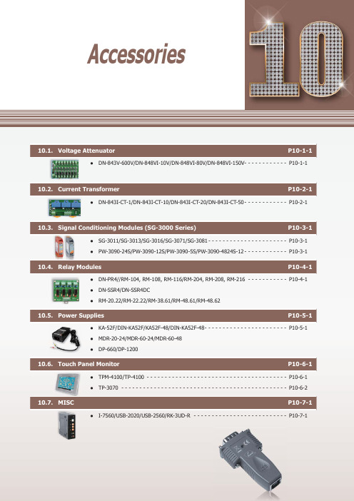
P10-1-1●DN-843V-600V/DN-848VI-10V/DN-848VI-80V/DN-848VI-150V- - - - - - - - - - - - P 10-1-1Current P10-2-1●DN-843I-CT-1/DN-843I-CT-10/DN-843I-CT-20/DN-843I-CT-50 - - - - - - - - - - - - P 10-2-1P10-3-1●SG-3011/SG-3013/SG-3016/SG-3071/SG-3081 - - - - - - - - - - - - - - - - - - - - - - P 10-3-1 ●PW-3090-24S/PW-3090-12S/PW-3090-5S/PW-3090-4824S-12 - - - - - - - - - - - - P 10-3-1Relay Modules P10-4-1●DN-PR4//RM-104, RM-108, RM-116/RM-204, RM-208, RM-216 - - - - - - - - - - - P 10-4-1 ●DN-SSR4/DN-SSR4DC●RM-20.22/RM-22.22/RM-38.61/RM-48.61/RM-48.62Power Supplies P10-5-1●KA-52F/DIN-KA52F/KA52F-48/DIN-KA52F-48 - - - - - - - - - - - - - - - - - - - - - - - P 10-5-1 ●MDR-20-24/MDR-60-24/MDR-60-48 ●DP-660/DP-1200P10-6-1●TPM-4100/TP-4100 - - - - - - - - - - - - - - - - - - - - - - - - - - - - - - - - - - - - - - - P 10-6-1 ●TP-3070 - - - - - - - - - - - - - - - - - - - - - - - - - - - - - - - - - - - - - - - - - - - - - - P 10-6-2MISC P10-7-1●I-7560/USB-2020/USB-2560/RK-3UD-R - - - - - - - - - - - - - - - - - - - - - - - - - - P 10-7-1AccessoriesProfessional Provider of High Quality I ndustrial C omputer P roducts and D ata A cquisition S ystems Vol. PAC 2.0.0A c c e s s o r i e s101Vout1GND Vout2GND Vout3GND+Vs GND F .G.NC Vin 1 -Vin 1+NC Vin 2 -Vin 2+NC Vin 3 -Vin 3+Vin 1 -Vin 1+Vin 2 -Vin 2+Vin 3 -Vin 3+Vin 4 -Vin 4+Vin 5 -Vin 5+Vin 6 -Vin 6+Vin 7 -Vin 7+Vin 8 -Vin 8++Vs GND F .G.Vout1 +OP Amp1OP Amp2OP Amp3OP Amp4OP Amp5OP Amp6OP Amp7OP Amp8Vout1 -Vout2 +Vout2 -Vout3 +Vout3 -Vout4 +Vout4 -Vout5 +Vout5 -Vout6 +Vout6 -Vout7 +Vout7 -Vout8 +Vout8 -DN-843V-600VDN-848VI-10V/DN-848VI-80V/DN-848VI-150V10.1. Voltage AttenuatorThe DN-800V series are voltage input attenuator . The maximum input range is from ±80 V to +/- 600 V and can be attenuated to ±10 V . The "I" version provide 3000 V DC intra-modules isolation and 3000 V DC channel to channel isolation to avoid the noise interference from inputs to outputs or channel to channel. It can be used with the analog input modules such as I-7017 and I-87017 etc. to measure the high voltage.DN-848VI-80VDN-848VI-150VAC/DC Source InputHigh Voltage Input Measurement Linear Attenuation Ratio High Input ImpedanceChannel to Channel Isolation forDN-848VI-10V , DN-848VI-80V and DN-848VI-150V 4 kV ESD Protection 3 kV Surge Protection RoHS ComplianceOperating Temperature: -25 ~ +75°C Easily Wire ConnectionDN-848VI-10VDN-843V-600V IntroductionApplicationsAppearanceProgrammable Automation Controller Products10-1-2Website:E-mail:*******************.PAC2.0.00Accessories101General Channels 8883Input Type AC/DC VoltageInput Range +/- 10 V pp+/- 80 V pp+/- 150 V pp+/- 600 V ppOutput Range +/- 10 V pp Accuracy1% of FSRChanel to Channel Isolation Yes, 3000 V DC-Bandwidth 30 KHz100 KHzInput Impedance> 1 M ΩIntra-module Isolation, Input to Output 3000 V DC -EMS Protection ESD (IEC 61000-4-2)+/- 4 kV contact for power line, input and output channels , +/- 8 kV air for random pointSurge (IEC 61000-4-5)+/- 3 kV for power linerPower Input Input Range +10 ~ +30 V DCPower Consumption 9.2 W9.2 W9.2 W0.56 WMechanicalDimensions (W x L x H)122 mm x 174 mm x 33 mm122 mm x 174 mm x 24.5 mmInstallation DIN-Rail MountingEnvironment Operating Temperature -25 ~ + 75°C Storage Temperature -30 ~ +75°CHumidity10 ~ 90% RH (non-condensing)8-channel 10 V Voltage Attenuator (RoHS)8-channel 80 V Voltage Attenuator (RoHS)8-channel 150 V Voltage Attenuator (RoHS)3-channel 600 V Voltage Attenuator (RoHS)MDR-20-24 CR24 V/1 A, 24 W Power Supply with DIN-Rail Mounting (RoHS)I-7017-G CR 8-channel Analog Input Module (RoHS)I-87017-G CR 8-channel Analog Input Module (RoHS)Selection GuideDN-84-x xx xxx Number of Channels 3: 3 channels 8: 8 channelsV: VoltageI: Channel to channel IsolationInput Voltage RangeDimensions (Units: mm)Bottom View Top View Bottom ViewTop View Left View Front View Rear ViewRight View Left View Front View Rear ViewRight View Speci fi cationsOrdering InformationAccessoriesProfessional Provider of High Quality I ndustrial C omputer P roducts and D ata A cquisition S ystems Vol. PAC 2.0.00102A c c e s s o r i e sDN-843I-CT-20DN-843I-CT-50DN-843I-CT-10DN-843I-CT-1 10.2. Current TransformerThe maximum input range is from ±1 A to +/- 50 A and can be attenuated to from ±1.6 V to ±10 V . The "I" version provide 3000 V DC intra-modules isolation and 3000 V DC channel to channel isolation to avoid the noise interference from inputs to outputs or channel to channel. It can be used with the analog input modules such as I-7017 and I-87017 etc. to measure the high current.AC/DC Source Input Linear Attenuation RatioHigh Current Input MeasurementIsolation InputChannel to Channel Isolation4 kV ESD Protection RoHS ComplianceOperating Temperature: -25 ~ +75°C Easily Wire ConnectionInstallationCh1 Current InputCh2 Current InputCh3 Current Input24 V DCCh1 OutputCh2 OutputCh3 OutputF.G. IntroductionApplicationsProgrammable Automation Controller Products10-2-2Website:E-mail:*******************.PAC2.0.00Accessories102General Channels 3Input Type AC/DC CurrentInput Range +/- 1 A+/- 10 A+/- 20 A+/- 50 AOutput Type AC/DC VoltageOutput Range +/- 1.6 V pp+/- 10 V pp+/- 10 V pp+/- 4 V ppCT Type Solid Core (closed)Accuracy1% of FSR Chanel to Channel IsolationYes, 3000 V rmsIntra-module Isolation, Input to Output 3000 V DC Bandwidth 50 KHz Input Impedance > 1 M ΩEMS Protection ESD (IEC 61000-4-2)+/- 4 kV contact for power line, input and output channels, +/- 8 kV air for random pointPower Input Input Range +10 ~ +24 V DCPower Consumption 1.2 WMechanicalDimensions (W x L x H)148 mm x 83 mm x 39 mmInstallation DIN-Rail Mounting Environment Operating Temperature -25 ~ + 75°C Storage Temperature -30 ~ +75°CHumidity10 ~ 90% RH (non-condensing)3-channel 1 A Current Transformer (RoHS)3-channel 10 A Current Transformer (RoHS)3-channel 20 A Current Transformer (RoHS)3-channel 50 A Current Transformer (RoHS)MDR-20-24 CR24 V/1 A, 24 W Power Supply with DIN-Rail Mounting (RoHS)I-7017-G CR 8-channel Analog Input Module (RoHS)I-87017-G CR8-channel Analog Input Module (RoHS)DN-84--xxxx xC: CurrentCT: Current TransformerInput Current RangeBottom ViewTop ViewLeft ViewFront ViewRight ViewNumber of Channels3: 3 channelsSelection GuideDimensions (Units: mm)Speci fi cationsOrdering InformationAccessoriesI C P roducts and D ata A cquisition S ystems Vol. PAC 2.0.00103A c c e s s o r i e s10.3. Signal Conditioning Modules (SG-3000 Series)DescriptionSG-3016SG-3071SG-3081PicturesAnalog Input Channel 11111Wiring Differential 2/3/4 wiresDifferential Differential Differential Signal ThermocoupleRTDStrain GaugeVoltage Current Type Type J, K, T , E, R, S, B, N, C, L,M, L2Pt100 α=0.00385, Pt100α=0.003916, Ni 120, Pt1000α=0.00385±10 mV , ±20 mV , ±30 mV ,±50 mV , ±100 mV ±5 V ,±10 V 0 ~ 20 mA, 4 ~ 20 mAResolution 12-bit 12-bit ---Accuracy ±0.2% of FSR±0.1% of FSR±0.1% of FSR±0.1% of FSR±0.1% of FSRInput Impedance 1.8 M Ω-- 1.6 M Ω250 ΩExcitation Voltage --0 ~ 10 V--Analog Output Channel 11111Current Output 0 ~ 20 mA 0 ~ 20 mA, 4 ~ 2 0mA 0 ~ 20 mA0 ~ 20 mA, 4 ~ 20 mA0 ~ 20 mA, 4 ~ 20 mA Voltage output 0 ~ 10 V0 ~ 5 V , 0 ~ 10 V±5 V , ±10 V , 0 ~ 5 V , 0 ~ 10 V±5 V , ±10 V0 ~ 5 V , 0 ~ 10 VSystem 3-way Isolation 1000 V DC Power Input 10 ~ 30 V DCPower Consumption 1.44 W1.2 W1.44 W 1.8 W1.61 WOperating Temperature -25 ~ +75°CDimensions (W x H x D)25 mm x 114 mm x 71 mmPW-3090-5SPW-3090-4824S-12PicturesInput 18 ~ 36 V (non-regulated)18 ~ 36 V (non-regulated)18 ~ 36 V (non-regulated)48 V (non-regulated)Output ********(Max.)********(Max.)5 V @ 2 A (Max.)********(Max.)Isolation 1000 V DCEf fi ciency83% Typical Operating Temperature -25 ~ +75°CDimensions (W x H x D)25 mm x 114 mm x 71 mmSG-3000 series signal conditioning modules are used to accept wide range of input signals, such as voltage, current, temperature (thermocouple and RTD) and provide 0 ~ 10 V DC , 0 ~ 20 mA, 4 ~ 20 mA output signals. It gives following good features for industrial applications • 3-way (power/input/output) isolation (1000 V DC )• Wide operating temperature (-25 ~ +75°C)• DIN-Rail mounting• Input and output connectors on the opposite side • Signal range con fi gureable by swtichIntroductionApplicationsProgrammable Automation Controller Products10-4-1Website:E-mail:*******************.PAC2.0.00Accessories104RM-38.61RM-48.61RM-48.62PicturesRelay Finder 20.22.9.024.4000Finder 22.22.9.024.4000Finder 34.51.7.024.0010FINDER - 40.61.7.024.0000FINDER - 44.62.7.024.0000Type Step RelayPower RelayChannel 1ContactForm A (DPST)Form A (DPST)Form C (SPDT)Form C (SPDT)Form C (SPDT)Operating Voltage Range 230 V AC 230 V AC 250 V AC 250 V AC 250 V AC Max. Load Current 16 A 20 A 6 A 16 A 10 A Operate Time 15 ms 15 ms 5 ms 7 ms 7 ms Release Time 8 ms8 ms3 ms 3 ms3 msLED Indicator -MechanicalDimensions (W x L x D)17.5 mm x 84 mm x 62.7 mm 76.5 mm x 6.5 mm x 89 mm75 mm x 15.5 mm x 78.5 mmInstallationDIN-Rail MountingNote1: RM-38.61: 5 pcs in one packageRM-48.61: 4 pcs in one package RM-48.62: 4 pcs in one packageNote2: RM-38-093.20is a 20-way jumper link for RM-38.61DN-SSR4PicturesRelay A5P-204UD3P-054Type Solid-State Relay Channel 4 channels ContactForm A (SPST)Operating Voltage Range 250 V AC /30 V DC50 V DCMax. Load Current 4 AOperate Time 1/2 Cycle + 1ms and below 0.5 ms and below (Resistance load)Release Time 1/2 Cycle + 1ms and below0.5 ms and below (Resistance load)LED Indicator Yes (for Relay status)MechanicalDimensions (W x L x D)101 mm x 77 mm x 66 mmInstallationDIN-Rail MountingPicturesRelay VE-24H5-K FINDER - 40.61.7.024.0000FINDER - 44.52.7.024.0000Type Power Relay Channel 4RM-104: 4 channels RM-108: 8 channels RM-116: 16 channels RM-204: 4 channels RM-208: 8 channels RM-216: 16 channels ContactForm C Form C (SPDT)Form C (DPDT)Operating Voltage Range 250 V AC /30 V DC250 V AC 250 V AC Max. Load Current 5 A 16 A 6 A Operate Time 10 ms (Typical)7 ms (Typical)8 ms (Typical)Release Time 5 ms (Typical)3 ms (Typical) 5 ms (Typical)LED Indicator Yes (for Relay status)MechanicalDimensions (W x L x D)96 mm x 103 mm x 34 mmRM-104: 79 mm x 87 mm x 63 mm RM-108: 135 mm x 87 mm x 63 mm RM-116: 270 mm x 87 mm x 63 mmRM-204: 90 mm x 87 mm x 63 mm RM-208: 169 mm x 87 mm x 63 mm RM-216: 327 mm x 87 mm x 63 mmInstallationDIN-Rail Mounting10.4. Relay ModulesI ndustrial C omputer P roducts and D ata A cquisition S 105A c c e s s o r i e s10.5. Power SuppliesModelsKA-52F DIN-KA52F KA-52F-48DIN-KA52F-48Input Range 100 ~ 250 V AC Frequency 50 ~ 60 HzOutput Power 24 V DC /1.04 A Max., 25 W48 V DC /0.52 A Max., 25 WMechanicalDimensions(W x H x D, Units: mm)54 x 93 x 36 68 x 107 x 50 54 x 93 x 36 68 x 107 x 50 Installation No-mountingDIN-Rail MountingNo-mountingDIN-Rail MountingEnvironmentalOperating Temperature 0 ~ +50°C Storage Temperature-20 ~ +85°CModelsMDR-20-24MDR-60-24MDR-60-48Input Range 100 ~ 250 V AC Frequency 50 ~ 60 HzOutput Power 24 V DC /1 A Max., 24 W24 V DC /2.5 A Max., 60 W48 V DC /1.25 A Max., 60 WMechanicalDimensions (W x H x D)22.5 mm x 90 mm x 100 mm 40 mm x 90 mm x 100 mm 40 mm x 90 mm x 100 mmInstallation DIN-Rail MountingEnvironmental Operating Temperature -20 ~ +70°C Storage Temperature-20 ~ +85°CModelsDP-660DP-1200Input Range 100 ~ 250 V AC Frequency 50 ~ 60 HzOutputPower 24 V DC /2.5 A Max., 60 W and5 V DC /0.5 A Max., 2.5 W24 V DC /5.0 A Max., 120 WMechanicalDimensions (W x H x D)44 mm x 145 mm x 158 mm 65 mm x 111 mm x 125 mmInstallation DIN-Rail MountingEnvironmentalOperating Temperature 0 ~ +50°C -10 ~ +70°C Storage Temperature-20 ~ +85°C-25 ~ +85°CKA-52F CR 24 V DC /1.04 A, 25 W Power Supply (RoHS)DIN-KA52F CR 24 V DC /1.04 A, 25 W Power Supply with DIN-Rail Mounting (RoHS)KA-52F-48 CR 48 V DC /0.52 A, 25 W Power Supply (RoHS)DIN-KA52F-48 CR48 V DC /0.52 A, 25 W Power Supply with DIN-Rail Mounting (RoHS)MDR-20-24 CR 24 V DC /1 A, 24 W Power Supply with DIN-Rail Mounting (RoHS)MDR-60-24 CR 24 V DC /2.5 A, 60 W Power Supply with DIN-Rail Mounting (RoHS)MDR-60-48 CR48 V DC /1.25 A, 60 W Power Supply with DIN-Rail Mounting (RoHS)DP-660 CR 24 V DC /2.5 A, 60 W and 5 V DC /0.5 A, 2.5 W Power Supply with DIN-Rail Mounting (RoHS)DP-1200 CR24 V DC /5.0 A, 120 W Power Supply with DIN-Rail Mounting (RoHS)KA-52F/DIN-KA52F KA52F-48/DIN-KA52F-48MDR-20-24MDR-60-24MDR-60-48DP-660DP-1200KA-52F KA-52F-48MDR-60-24/MDR-60-48DP-1200MDR-20-24DP-660DIN-KA52F DIN-KA52F-48Speci fi cationsSpeci fi cationsSpeci fi cationsOrdering InformationOrdering InformationOrdering InformationProgrammable Automation Controller Products10-6-1Website:E-mail:*******************.PAC2.0.00Accessories106TPM-4100TP-410010.6. Touch Panel MonitorTPM-4100/TP-410010.4" Touch Panel Monitor10.4" LCD supports 800 x 600 resolution Resistive Touch Panel Full-function OSD controlDriver Support: Windows 2k/XP/Vista/7/WESWinCE 5.0/6.0 LED backlight technology Aluminum Casing for TPM-4100 IP65 Comlipant Front PanelWide operating temperature: -25 ~ +75°CTPM-4100TP-4100Display Size 10.4”Resolution 800 x 600Max. Color 16.7 M Brightness (cd/m2)320Contrast Ratio 500 : 1Viewing Angle (H/V)140/130Backlight Life (hrs)50,000Touch Panel 4-wire5-wireanalog resistive, RS-232 or USB1.1 (Type B) interfaceInput SignalVGA (Analog RGB)MMI (Man Machine Interface)OSD Control Functions: Brightness, Contrast, Phase, Horizontal Position,Vertical Position and SharpnessPower Switch YesLED Indicators Power , Display signal is detectedPower Input Range +12 ~ 48 V DCPower Consumption 8.5 WMechanical MaterialAluminumPlasticDimensions (W x L x H)293 mm x 231 mm x 53 mm290 mm x 228 mm x 53 mm Installation Panel MonutingPanel Monuting, VESA (75 × 75) MountingIngress Protection Front panel: IP65Environmental Operating Temperature -25 ~ +75°C Storage Temperature -30 ~ +80°CAmbient Relative Humidity10 ~ 90% RH (non-condensing)10.4" (800 x 600) resistive touch panel monitor with RS-232 or USB interfaceAccessories: Power supply, VGA cable, RS-232 cable, USB cable, Mounting clamps and screws TP-4100 with Aluminum Casing273210.8TPM-4100 Dimensions (Units: mm)Speci fi cationsAppearanceOrdering InformationUSB USBOSD OSDRS-232RS-232VGAVGA Power Switch Power Switch VESA (75 × 75) Mounting12 ~ 48 DC IN12 ~ 48 DC INI ndustrial C omputer P roducts and D ata A cquisition S ystems Vol. PAC 2.0.00106A c c e s s o r i e sTP-30707" Touch Panel Monitor7" LCD supports 800 x 480 resolution Resistive Touch Panel Full-function OSD controlDriver Support: Windows 2k/XP/Vista/7/WESWinCE 5.0/6/0 LED backlight technology IP65 Comlipant Front PanelWide operating temperature: -20 ~ +70°CTP-3070Display Size 7”Resolution 800 x 480Brightness (cd/m2)320Contrast Ratio 500 : 1Viewing Angle (H/V)140/120Backlight Life (hrs)20,000Touch Panel 4-wire, analog resistive, RS-232 or USB1.1 (TypeB) interfaceInput SignalVGA (Analog RGB)MMI (Man Machine Interface)OSD Control Functions: Brightness, Contrast, Clock, Phase, Horizontal Position, Vertical Position and SharpnessPower Switch YesLED Indicators Power , Display signal is detectedPower Input Range +12 ~ 48 V DCPower Consumption 5 WMechanicalDimensions (W x L x H)213 mm x 148 mm x 44 mmCasingPlastic Ingress Protection Front panel: IP65Environmental Operating Temperature -20 ~ +70°C Storage Temperature -30 ~ +80°CAmbient Relative Humidity10 ~ 90% RH (non-condensing)7" (800 x 480) resistive touch panel monitor with RS-232 or USB interfaceAccessories: Power supply, VGA cable, RS-232 cable, USB cable, Mounting clamps and screwsDimensions (Units: mm)Speci fi cationsOrdering InformationProgrammable Automation Controller Products10-7-1Website:E-mail:*******************.PAC2.0.00Accessories 107InterfaceUSBCompatibility: USB 1.1 and 2.0 standards RS-232TxD, RxD, RTS, CTS, DSR, DTR, DCD, RI and GND; non-isolated Baud Rate300 ~ 115200 bps DriverWindows 98/ME/2000/XP/Vista (32/64-bit)/7 (32/64-bit)/LinuxMechanicalDimensions (W x H x D)33 mm x 60 mm x 15 mm Environmental Operating Temperature-25 ~ +75°C Storage Temperature -30 ~ +75°CInterfacePortsUpstream x 1 (Type B); Downstream x 4 (Type A)CompatibilitySpeci fi cation Rev. 2.0/1.1/1.0Transfer Speed480 Mbit/s-high speed mode Input Voltage Range+10 ~ +30 V DCMechanicalDimensions (W x H x D)33 mm x 107 mm x 78 mm InstallationDIN-Rail Mounting Environmental Operating Temperature -0 ~ +70°C Storage Temperature -20 ~ +80°CMechanical Dimensions (W x H x D)481 mm x 132 mm x 125 mm USB-2020 CR USB Audio Device (RoHS)RK-3UD-R 19" Rack Mounting Kit, 3U I-7560 CR USB to RS-232 Converter (RoHS)USB-2560 CR4-port Industrial USB 2.0 Hub (RoHS)USB-2560/S CR 4-port Industrial USB 2.0 Hub (RoHS) with GPSU06U-6 (Power Supply)RK-3UD-R I-7560InterfaceOutput ChannelsMono, Stereo (L + R)Input ChannelsMono, Stereo (L + R)ButtonHID volume up, volume down and Mute Input Voltage Range+10 ~ +30 V DCMechanicalDimensions (W x H x D)33 mm x 107 mm x 78 mm Installation DIN-Rail Mounting Environmental Operating Temperature-25 ~ +75°C Storage Temperature -40 ~ +85°C 10.7. MISC Speci fi cationsSpeci fi cationsSpeci fi cationsSpeci fi cationsOrdering InformationOrdering InformationOrdering Information Ordering Information USB to RS-232 Converter USB-2020USB-2560USB Audio Device 4-Port Industrial USB 2.0 Hub19" Rack Mounting Kit, 3UiP-84112-4-3 iP-88112-4-3 iP-84412-4-3 iP-88412-4-3 iP-8441-FD2-4-3 iP-8841-FD2-4-3 iP-84172-4-5Model Name PageiP-84472-4-5iP-88172-4-5iP-88472-4-5I-87005W5-2-1I-87013W5-2-1I-87015PW5-2-2I-87015W5-2-2I-8014W5-2-3I-8017DW5-2-3I-8017HCW5-2-3I-8017HW5-2-3I-8024DW5-2-3I-8024W5-2-3I-87017DW5-2-4I-87017RCDW5-2-4I-87017RCDW-AI5-2-4I-87017RCW 5-2-4I-87017RW 5-2-4I-87017W5-2-4I-87017W-A55-2-4I-87017ZW5-2-4I-87018PW5-2-5I-87018RW5-2-5I-87018W5-2-5I-87018ZW5-2-5I-87019PW5-2-6I-87019RW5-2-6I-87019ZW5-2-6I-87024W 5-2-7I-87024CW5-2-7I-87024DW 5-2-7I-87024RW 5-2-7I-87024UW 5-2-7I-87028CW5-2-7I-8040PW5-3-1I-8040W5-3-1I-8046W5-3-1I-8048W5-3-1I-8051W5-3-1I-8052W5-3-1I-8053W5-3-1I-8053PW5-3-1Model Name PageI-8058W5-3-1I-87040W5-3-2I-87040PW5-3-2I-87046W5-3-2I-87051W5-3-2I-87052W5-3-2I-87058W5-3-2I-87059W5-3-2I-87053W5-3-3I-87053PW5-3-3I-87053W-A55-3-3I-87053W-AC15-3-3I-87053W-E55-3-3I-8037W5-3-4I-8041W5-3-4I-8041RW5-3-4I-8041AW5-3-4I-8056W5-3-4I-8057W5-3-4I-8057RW5-3-4I-8057PW5-3-4I-8060W5-3-4I-8064W5-3-4I-8068W5-3-4I-8069RW5-3-4I-8069W5-3-4I-87037W5-3-5I-87041W 5-3-5I-87057W5-3-5I-87057PW5-3-5I-87061W5-3-5I-87064W5-3-5I-87065W5-3-5I-87066W5-3-5I-87068W5-3-5I-87069W5-3-5I-87069PW5-3-5I-8042W5-3-6I-8050W5-3-6I-8054W5-3-6I-8054RW5-3-6I-8055W5-3-6Model Name PageI-8063W5-3-6I-87042W5-3-7I-87054W5-3-7I-87055W5-3-7I-87063W5-3-7I-8026PW5-4-1I-87016W5-4-1I-87026PW5-4-1I-87089W/S5-5-1I-8084W5-6-1I-8088W5-6-1I-87082W5-6-1I-87084W5-6-1I-87088W5-6-1I-8092F5-7-1I-8093W5-7-1I-80945-7-1I-8094A5-7-1I-8094F5-7-1I-8094H5-7-1I-75105-8-1I-7510A5-8-1I-7510AR5-8-1I-75135-8-1I-7514U5-8-1I-7520 5-8-1I-7520A5-8-1I-7520AR5-8-1I-7520R5-8-1I-7520U45-8-1I-75515-8-1I-8112iW5-8-1I-8114iW5-8-1I-8114W5-8-1I-8142iW5-8-1I-8144iW5-8-1I-25325-9-2I-25335-9-2I-75305-9-2I-7530A5-9-2I-7530A-MR5-9-2I-7530-FT5-9-2Model IndexI-75315-9-2 I-75325-9-2 I-7540D5-9-2 I-7540D-MTCP5-9-2 I-7540D-WF5-9-2 I-75655-9-2I-7565-H15-9-2 I-7565-H25-9-2 I-8120W5-9-2 I-8123W5-9-2 I-8124W5-9-2 I-871235-9-2 I-871245-9-2 I-87H17W5-10-1 I-87H24W5-10-1 I-75475-10-1 I-75675-10-1 I-75705-10-1 I-8172W5-11-1 I-8212W5-12-1 I-8212W-3GWA5-12-1 I-8213W5-12-1 I-8213W-3GWA5-12-1 I-87211W 5-12-1 iP-8441-MTCP6-3-2 iP-8841-MTCP6-3-2 I-7188XG7-1-6 I-7188XGD7-1-6 I-71887-1-9 I-7188D7-1-9 I-7188XA7-1-9 I-7188XAD7-1-9 I-7188XB7-1-9 I-7188XBD7-1-9 I-7188XC7-1-9 I-7188XCD7-1-9 I-7188EA7-1-11 I-7188EAD7-1-11 I-7188EX7-1-11 I-7188EXD7-1-11 I-756010-7-1 iDCS-88309-1-3USB-87P25-4-2USB-87P45-4-2USB-87P85-4-2USB-202010-7-1USB-256010-7-1WP-8131 2-2-3WP-84312-2-3WP-88312-2-3WP-81412-2-3WP-84412-2-3WP-88412-2-3WP-80512-2-3WP-83512-2-3WP-87512-2-3WP-81372-2-6WP-84372-2-6WP-88372-2-6WP-81472-2-6WP-84472-2-6WP-88472-2-6WP-80572-2-6WP-83572-2-6WP-87572-2-6WP-81392-2-11WP-84392-2-11WP-88392-2-11PROFI-82556-6-2PROFI-84556-6-2PROFI-88556-6-2PW-3090-5S10-3-1PW-3090-12S10-3-1PW-3090-24S10-3-1PW-3090-4824S-1210-3-1USB-87P15-4-2iDCS-8830R9-1-3PROFI-81556-6-2XP-8349-Atom-CE62-1-14 XP-8749-CE62-1-14 XP-8749-Atom-CE62-1-14 X1017-2-3 X1067-2-3 X1077-2-3 X1107-2-3 X1117-2-3 X2007-2-3 X2027-2-3 X2037-2-3 X3027-2-3 X3037-2-3 X3047-2-3 X3057-2-3 X3087-2-3 X3107-2-3 X3247-2-3 X5037-2-3 X5047-2-3 X5057-2-3 X5067-2-3 X5077-2-3 X5087-2-3 X5097-2-3 X5107-2-3 X510-1287-2-3 X5117-2-3 X5187-2-3 X6037-2-3 X6077-2-3 X6087-2-3 X7027-2-3 X7037-2-3 XV1168-4-1 XV107Ai8-4-2 XV107i8-4-2 XV110i8-4-2 XV111Ai8-4-2 XV111i8-4-2 XW1078-4-2 XW107i8-4-2μPAC-51078-1-7μPAC-5107D8-1-7μPAC-52078-1-7μPAC-5207D8-1-7μPAC-53078-1-7μPAC-5307D8-1-7μPAC-55078-1-7μPAC-5507D8-1-7 XW110i8-4-2XV304i8-4-3XV305i8-4-3XV308i8-4-3XV310i8-4-3XW3048-4-4XW3108-4-4XW310C8-4-4XW5068-4-5XW5078-4-5XW5088-4-5XW5098-4-5XW511i8-4-5XW5148-4-5μμPAC-7186EX 7-1-4μPAC-7186EXD 7-1-4μPAC-7186EX-FD 7-1-4μPAC-7186EXD-FD 7-1-4μPAC-7186EX-SM 7-1-4μPAC-7186EXD-SM 7-1-4μPAC-7186EG7-1-6μPAC-7186EG-D7-1-6μPAC-50018-1-6μPAC-5001D8-1-6μPAC-5001-FD8-1-6μPAC-5001D-FD8-1-6μPAC-5101 8-1-6μPAC-5101D 8-1-6μPAC-52018-1-6μPAC-5201D8-1-6μPAC-53018-1-6μPAC-5301D8-1-6μPAC-55018-1-6μPAC-5501D8-1-6μPAC-5801 8-1-6μPAC-5801D8-1-6μPAC-59018-1-6μPAC-5901D8-1-6μPAC-50078-1-7μPAC-5007D8-1-7WP-81492-2-11WP-84492-2-11WP-88492-2-11WP-80592-2-11WP-83592-2-11WP-87592-2-11WP-51418-2-4WP-5141-OD8-2-4WP-52318-2-6WP-5231-2G8-2-6WP-5231-3G8-2-6WP-5231-GPS8-2-6WP-5231-WF8-2-6WP-5231-ZH8-2-6WP-5231-ZS8-2-6WP-51478-2-8WP-5147-OD8-2-8WP-51498-2-11WP-5149-OD8-2-11XXP-8041 2-1-5XP-8141-Atom2-1-5XP-83412-1-5XP-8341-Atom2-1-5XP-87412-1-5XP-8741-Atom2-1-5XP-8041-CE62-1-7XP-8141-Atom-CE62-1-7XP-8341-CE62-1-7XP-8341-Atom-CE62-1-7XP-8741-CE62-1-7XP-8741-Atom-CE62-1-7XP-8047-CE62-1-9XP-8147-Atom-CE62-1-9XP-8347-CE62-1-9XP-8347-Atom-CE62-1-9XP-8747-CE62-1-9XP-8747-Atom-CE62-1-9XP-8049-CE62-1-14XP-8149-Atom-CE62-1-14XP-8349-CE62-1-14 Model Index。
日本横河DLM2000混合信号示波器产品说明

2008年10月 2008年11月21日
Yokogawa Shanghai Trading Co.,Ltd
35
Yokogawa Shanghai Trading Co., Ltd.
17
使用示波器进行变频器测试的主要项目
PWM信号测试
观测基波波形 对基波波形进行测量和分析
电机转速信号测量
设定需要测量的范围并测量时间 对所设定的时间范围内的转速脉冲进行计数
Yokogawa University 2007
没有实际滤波器的影响,基波波形参数测量的精度提高
Yokogawa Shanghai Trading Co.,Ltd.
24
DLM2000对电机转速脉冲进行测量
在放大区域将光 标精确定位在开 始脉冲的边沿上
自动光标测量 自动脉冲计数
在放大区域将光 标精确定位在结 束脉冲的边沿上
Zoom1
Zoom2
18
PWM基波测量面临的问题
变频器
PWM信号
基波信号
低通滤波器
截至频率:<1KHz
问题
需要花费大量的时间搭建和调试低通滤波器 滤波器对PWM信号产生影响,难以观测到“理想”基波信号 PWM信号发生变化后,需要重新调整滤波器
Yokogawa Shanghai Trading Co.,Ltd.
双总线触发
Yokogawa Shanghai Trading Co.,Ltd
10
运算功能
运算
2个运算波形(Math或REF) +,-,x,滤波,积分,计数(边沿/角度)
运算滤波
低通或高通滤波器 截至频率:0.01Hz-500MHz
用户自定义运算(即将推出)
横河ADMAGSE系列电磁流量计中文说明书

横河电机株式会社使用说明书SE100MJ/NJ, SE200MJ/NJ 一体型电磁流量计IM 01E10B00-01C-CIM 01E10B00-01C-C第10版iIM 01E10B00-01C-CFD No. IM 01E10B00-01C-C 第10版:2002年4月 (YK)横河电机株式会社 版权所有2003目录1.简介..........................................................................................................1-12.操作注意事项............................................................................................2-12.1检查信号和规格...................................................................................2-12.2附件.....................................................................................................2-12.3存放注意事项.......................................................................................2-12.4安装场所注意事项................................................................................2-12.5清洁注意事项.......................................................................................2-12.6更改转换器方向注意事项.....................................................................2-13.安装..........................................................................................................3-13.1管道设计注意事项................................................................................3-13.2操作注意事项.......................................................................................3-33.2.1一般注意事项................................................................................3-33.2.2流量计管道....................................................................................3-43.3安装.....................................................................................................3-43.3.1公称通径为15mm ~ 40mm 的夹持型............................................3-43.3.2公称通径为50mm ~ 200mm 的夹持型..........................................3-63.3.3公称通径为15mm ~ 200mm 的法兰型..........................................3-83.4接线注意事项.....................................................................................3-103.4.1保护性接地..................................................................................3-103.4.2一般注意事项..............................................................................3-103.4.3电源和输出电缆..........................................................................3-103.4.4连接直流电源..............................................................................3-113.4.5接线端口.....................................................................................3-113.4.6连接到外部仪器..........................................................................3-124.基本操作步骤............................................................................................4-14.1液晶显示器(LCD )............................................................................4-14.2显示数据的类型...................................................................................4-24.2.1改变显示模式的最初步骤..............................................................4-34.2.2流量显示模式................................................................................4-54.2.3设置模式.......................................................................................4-64.2.4报警显示模式................................................................................4-74.2.5自动调零模式................................................................................4-84.2.6显示器错误模式............................................................................4-85.功能和数据设置........................................................................................5-15.1设置流量量程.......................................................................................5-15.2电源频率(仅对于直流电源)..............................................................5-45.3其它功能和设置...................................................................................5-45.3.1脉冲输出.......................................................................................5-45.3.2内部累计值显示............................................................................5-65.3.3重新设置累计显示.........................................................................5-75.3.4阻尼时间常数................................................................................5-85.3.5发生报警时的电流输出..................................................................5-85.3.6流向倒置.......................................................................................5-8iiIM 01E10B00-01C-C5.3.7限制电流输出................................................................................5-95.3.8正向和反向流量测量...................................................................5-105.3.9自动双量程切换..........................................................................5-115.3.10在流量下限(流量切换)的报警输出..........................................5-125.3.11累计切换输出..............................................................................5-135.3.12报警输出.....................................................................................5-145.3.13允许/禁止数据设置......................................................................5-145.3.14选择特殊应用程序项目的步骤.....................................................5-155.3.15采样比限制..................................................................................5-156.通过智能终端(BT200)的操作...............................................................6-16.1BT200连接...........................................................................................6-16.2BT200键盘布局图................................................................................6-26.3BT200按键功能...................................................................................6-36.4显示流量数据.......................................................................................6-46.5设置参数..............................................................................................6-56.5.1设置流量量程................................................................................6-56.5.2电源频率(仅对于直流电源).......................................................6-76.6其它功能..............................................................................................6-76.6.1用户自定义单位............................................................................6-76.7其它要点..............................................................................................6-87.通过HART 通信装置的操作.......................................................................7-17.1在线通信条件.......................................................................................7-17.1.1ADMAG SE 和HART 通信装置的连接............................................7-17.1.2通信线要求....................................................................................7-27.2HART 通信装置(275型)的基本操作.................................................7-37.2.1按键和功能....................................................................................7-37.2.2显示..............................................................................................7-47.2.3调用菜单地址................................................................................7-47.2.4输入、设置和发送数据..................................................................7-67.3参数.....................................................................................................7-87.3.1参数配置.......................................................................................7-87.3.2数据更新.......................................................................................7-87.3.3菜单树...........................................................................................7-97.3.4设置参数.....................................................................................7-128.实际操作...................................................................................................8-18.1预调零操作..........................................................................................8-18.1.1使用数据设置键进行调零..............................................................8-18.1.2使用BT200调零.............................................................................8-28.1.3使用HART 通信装置调零...............................................................8-38.2自诊断功能..........................................................................................8-48.2.1报警发生过程中的输出状态..........................................................8-48.2.2使用HART 通信装置进行自诊断....................................................8-58.2.3错误说明和对策............................................................................8-69.维修..........................................................................................................9-19.1回路测试(测试输出)........................................................................9-19.1.1使用数据设置键进行测试输出设置................................................9-19.1.2使用BT200进行测试输出设置.......................................................9-29.1.3使用HART通信装置进行测试输出设置.........................................9-39.2问题解答..............................................................................................9-59.2.1无显示...........................................................................................9-59.2.2不稳定零点....................................................................................9-69.2.3显示与实际流量不一致..................................................................9-710.概述........................................................................................................10-111.参数列表.................................................................................................11-111.1ADMAG SE显示和BRAIN终端用参数...............................................11-111.2HART通信器用参数...........................................................................11-712.隔爆型仪表.............................................................................................12-112.1CENELEC ATEX(KEMA)..................................................................12-112.2FM.....................................................................................................12-212.3CSA...................................................................................................12-212.4SAA...................................................................................................12-313-113.压力仪表指示..........................................................................................iii IM 01E10B00-01C-C1.简介本仪表在发货前已经过全面调试。
掌握霍尼韦尔及横河DCS基础操作

Local Control Network
无线变送器
HPM
BC Controller
TPS/TDC投资保护 Experion on LCN
SIL 3 安全系统 Safety Manager
历史趋势
查看历史趋势: 查看历史趋势的方法有2中 方法一: 1.在Native Window中点击History。出现一个下拉菜单 2.在下拉菜单中会点解TREND.点击TREND后会出现一
串级控制
2. 串级控制系统的工作过程 当扰动发生时,破坏了稳定状态,调节器进行工
作。根据扰动施加点的位置不同,分种情况进行分析: * 1)扰动作用于副回路 * 2)扰动作用于主过程 * 3)扰动同时作用于副回路和主过程 分析可以看到:在串级控制系统中,由于引入了
一个副回路,不仅能及早克服进入副回路的扰动,而 且又能改善过程特性。副调节器具有“粗调”的作用, 主调节器具有“细调”的作用,从而使其控制品质得 到进一步提高。
调节阀的作用方式
输出作用方式
正作用: 主控阀门开度信号(0%~100%)—现场阀门开度(0%~100%) 反作用: 主控阀门开度信号(0%~100%)—现场阀门开度(100%~0%)
控制作用方式(针对投自动调节阀而言)
正作用: PV>SV 阀门开度↑,PV ↓(如:泄压阀) 反作用: PV<SV 阀门开度↑,PV ↑
操作监视窗口介绍
3.操作指导信息按钮 ☞点选此按钮可以调出操作指导信息窗口,并可对操作指导 信息进行确认。出现操作指导信息后,按钮会有相应提示。
☞绿色闪烁:表示出现操作指导信息,并且其内容未被确认。 ☞绿色持续:表示出现操作指导信息,并且所有内容已被确认。
4.信息监视按钮
横河川仪变送器手操器说明书
Users ManualYHC 4150X 系列 HART® 通讯器YHC 4150X HART ®通讯器IM 61A YHC1-E-A 第三版: 2008年5月YHC 4150X HART 通讯器用户手册重要提示产品的重要信息都包含在本手册中,在操作前请仔细阅读手册全部内容。
为保证操作者和系统的安全,在调试、使用或维护产品前,必须彻底理解本手册内容。
辅助信息要获得用户支持,请与当地横河公司事务所、代表或代理商直接联系。
要获得各地代表名单及联系方式,请访问我们的网站 。
HART®是HART通信基金会的注册商标。
YHC 4150X HART 通讯器用户手册目录YHC 4150X 通讯器概述 (1)显示器 (1)标题栏符号 (2)键盘 (2)字母数字/符号输入 (3)左 / 右箭头键 (4)软键 (4)翻查操作键 (5)一般操作 (5)电源选项 (5)通讯/AC适配器 (5)菜单导航 (6)启动 YHC (6)YHC主菜单显示 (8)YHC组态设置 (8)1 用户 (8)2 应用 (8)3 锁定(锁定、PV Prompt设定、锁定详细资料) (8)锁定代码 (8)解除锁定 (9)锁定代码更改 (9)4 时钟/定时器 (9)1 时钟编辑 (9)2 背光 (10)3 关闭定时器 (10)5 其它 (10)1 型号 (10)2 电池型号选择 (10)3 HART通讯模式选择 (10)4输入PC通信模式 (10)5轮询类型: 自动(默认地址0)或数字(默认地址0-15) (11)电池安装/拆卸 (YHC所有型号) (12)外部连接 (12)通讯/AC 适配器连接 (12)HART 接线插座 / 导线设置 (13)危险场所使用 (14)本质安全操作 (14)YHC 4150X HART®通讯 (15)HART 命令 (15)HART 连接 (15)HART 通信 (16)初始屏幕 / 在线模式 (16)多点轮询(地址1-15) (17)数字轮询 (地址1-15) (17)自动和数字轮询默认值设置 (17)零地址设备手册发布 (18)离线菜单模式 (18)1 DOF文件列表 / 显示 (18)2组态列表 / 编辑 (18)3 组态创建 (19)4 组态删除 (19)删除单个组态 / 清除组态内存 (19)在线设置模式 (20)通信故障检查 (21)更多状态信息 (21)保存 / 发送组态功能 (21)DOF 存储器维护 (22)使用横河DMS软件编制HART组态文件 (23)YHC 4150X特殊和普通HART通讯 (23)普通HART通讯应用 (23)YHC 4150X固件和DOF文件更新 (24)概述 (24)谁可以使用下载地址 (24)对PC机的要求 (24)YHC更改准备 (24)使用DPC管理程序更新YHC (24)直接使用DOF下载网站 (25)使用DOF下载网站和DPC管理程序更新YHC (26)YHC 维修 (28)附录YHC 技术规格 (29)YHC 型号, 选项, 订货信息 (30)YHC 附件表 (30)本质安全型控制文件 (31)EC一致性声明 (32)HART命令菜单树 ........................................................................................................................33-34 普通(HART 5) .. (33)EJA Rev 2 (34)YHC4150X HART 通讯器概述YHC 4150X HART 通讯器是一种全功能HART 通讯器, 支持通用命令、普通命令和设备特殊命令,可以完成设备的调试、组态和维护。
日本横河μR20000智能工业有纸记录仪产品说明

干球温度 湿球温度
测量环境试验数据,以简洁易懂的方式显示并记 录多种数据。
环境试验设备的数据显示和记录 (温调室的试验数据采集)
- Cu输入传感器(/N1选配件)等多种输入方式可供选择 - 监视和记录温度,振动时的数据及异常发生时的报警 - 通过连接DAQLOGGER,收集并分析异常发生时的数据
UART 数字 滤波器
Vref RTD放大器
控制器
扫描器控制
EEPROM
符合IP54标准的前罩
卓越的操作性能
◇ VFD 大屏幕点阵显示
(μR10000:101×16, μR20000:181×16) ◇ 显示操作向导,实现对话式设定操作 ◇ 新型记录纸盒,即使在记录过程中,也可
以方便地抽出记录纸浏览查询 ◇ 机内标配高亮度白色LED照明装置
a
b
7 送纸速度变更打印
8 手动打印
c
9 记录开始时间打印
d
* 设定模式中,可选择定时打印,报表打印或不打印。报表打印内容从以下选
e
择:仅每通道的AVE(平均值)、仅MIN(最小值)、仅MAX(最大值)、
f
MIN/MAX/AVE、SUM或INST(瞬时值)
部分压缩扩大记录 可放大记录需要详细记录的部分。
发送到文件服务器。
*即将支持μR20000。
8
能,可满足用户的不同需求,适用于多种应用场合。
μR10000
1
5 4
3
丰富的记录和打印功能
μR20000
8
4笔式机型
5
1
4
8
2 1
2
6
7
9 6通道打点式机型
5 7
6 4
横河 UT50A说明书
• 阳光直射或靠近加热器的位置
将本仪表安装在接近常温 23°C,具有稳定温度的场所。切勿将其安装在阳光直射或
靠近加热器的位置。否则会对仪表造成不良影响。
• 有大量油烟、蒸汽、水分、灰尘或腐蚀性气体的场所
油烟、蒸汽、水分、灰尘或腐蚀性气体会对本仪表造成不良影响。
• 靠近电磁场发生源的地方
切勿在仪表附近摆放磁铁或能产生磁力的工具。如果在强电磁场发生源附近使用本
些特定的应用场所,包括核电站设备、使用放射能的设备、铁路设施、航空设施 和医疗设备等。如果在这样的环境下使用,则用户需自行负责在系统附加设备中 包括以及保证个人安全的设备。 (5) 严禁对产品改装。
警告
l 电源 在打开电源前,确保仪表的电源电压符合电源电压。
l 切勿在可燃性气体中使用本仪表 请不要在有可燃性气体、爆炸性气体或蒸气的场所操作本仪表,在这样 的环境下使用本仪表非常危险,在有高浓度的腐蚀性气体(H2S,SOX 等) 环境中长时间使用本仪表容易引起故障。
n UT55A
码
说明
UT55A
数字温度控制器
(具有传送输出或 15 V DC 回路电源、3 个 DI 端口、 3 个 DO 端口) (电源:100-240 V AC)
-0
类型 1: 基本控制
-1
-2
标准类型 位置比例类型 加热 / 冷却类型
0
无
远程(1 个附加辅助模拟)输入、6 个附加 DI、5 个
150 mm
备 使 用 1.43 mm 的 厚 钢 板 或 1.6 mm 厚 的 未 镀 层 钢 板
制 作 的 外 罩, 外 罩 与 设 备 顶 部、 底 部 和 侧 面 至 少 距 离 150 mm。
150 mm
EJA智能变送器简单介绍仪表腾伟
EJA智能变送器简单介绍仪表腾伟我厂近几年采用了很多EJA智能变送器,这里我简单介绍一下这种变送器的一些功能参数。
EJA智能变送器制造商为日本横河电机株式会社(英文爼称YOKOGAWA),其为世界知剑的自动化仪表生产制造商,生产的EJA智能变送器采用世界上最先进的单晶硅谐振式传感器技术,是目前世界上最先进的变送器。
自95年进入中国市场以来,深受广大用户的青睐,成为变送器领域最具活力的名牌产品,2019年订货达12万台。
粋横河川仪有限公司(英文缩写CYS)为日本横河电机株式会社与钉川仪总厂有限公司共同出资组建(横河电机占60%, **川仪占40%),生产EJA智能变送器,同时代理杯原产于日本横河电机的 EJA变送器,并为日本横河电机生产的EJA 变送器在中国的售后服务商。
粋横河川仪有限公司为横河电机在全球三大生产基地之一,以IS09000质量保证体系与日本横河电机5M质量管理方式相结合,采用苴先进的制造工艺和髙新设备,确保CYS制品与日本制品同一品质。
EJA压力、差压变送器技术性能要求1变送器为二线制。
输出信号:4-20mA标准信号;带BRAIN协议和LCD数显;电源: 24VDCo 2变送器在外接负载电阻至少为500Q时(24VDC供电),仍能正常工作。
3变送器带就地数显式数字指示表,此设备是标准配置.无此表头不会影响变送器的正常工作. 4变送器精度髙于±0.075 %。
阻尼可设置或可调。
5变送器在温度变化为50°C时,漂移量不超过最大量程的0.1%。
6变送器为线性输出(0-100%),在测量范囤内连续可调。
量程比最小应满足100: K具有零位正向迁移和负向迁移。
7变送器能通过手操编程器进行标左、组态、诊断和维护,组态的数拯保存在EPROM中。
失电后,变送器可以在重新启动后马上工作。
8变送器的法兰接头、排*引排液阀等部件的材质不得低于316不锈钢。
隔离膜片材质为哈氏合金,膜片不因单向过压造成永久性变形。
使用说明书-日本三和(sanwa)
数字转速表使用说明书三和电气计器株式会社日本东京都千代田区外神田2丁目4番4号电波大楼【1】安全注意事项*本手册中使用的标志以及产品上的标志的含义如下:以下操作是为了防止人身伤害,如烧伤和触电。
在使用本仪表时,请务必遵守:功能键:最大值:最小值:数值保持单位:组合参照“5-3非接触式测量方法”和“5-4接触式测量方法”。
数值显示单位:自动关机:接触式测定模式:电池消耗警注意:在非接触式测量时,请按照下图在旋转体上粘贴反射贴(附属品)。
旋转体照射光反射贴警告旋转速度(转/分)计数(个)间隔时间(ms)旋转速度(转/秒)注意警告警告1-1 警告标志说明非常重要的使用安全指示。
·警告信息是为了防止操作人员发生意外烧伤和触电。
·注意信息是为了防止损坏仪表。
:1-2 安全使用警告1.在测量过程中,为避免衣服,头发等被卷入旋转体, 请戴工作帽穿工作服并佩戴保护眼镜。
2.在测量过程中,请绝对不要用手去触摸旋转体。
3.被测量的旋转体有异常时,请勿使用本表。
4.旋转体对测量者有可能造成危险的部分请设计挡板等 保护措施,确保安全的测量环境。
5.除了更换电池以外,切勿尝试对仪表进行修理或改造。
6.请务必执行测量前检查和每年一次的点检。
注意1.使用本仪表时,请勿从高处摔落。
2.本仪表的检测窗口不要受到强烈的撞击。
3.请勿拆开本仪表的外壳,触摸内部电路板和器件, 或对其加工改造。
使用前,请阅读以下安全防范措施。
本说明书介绍如何使用您的数字转速表SE300。
请仔细地阅读本手册。
阅读后,请将手册与产品放在一起保管,以方便随时参考。
必须遵守 警告和 注意下的操作指示,以防止发生意外烧伤或触电。
接触式适配器固定螺丝孔三脚架用螺丝孔电池盖电源键发光/检测窗转动测量提示LED 表示部【2】用途与特长2-1 用途本表是测量马达等旋转体的转动圈数的非接触式手持转速计。
使用另售适配器 ENC-3接触式测量探头,可以作为接触式转速计使用。
日本横河公司集散控制系统(dcs)stardom概述.doc
日本横河公司集散控制系统(DCS)STARDOM概述1、DCS 硬件的详细描述及控制功能横河电机(YOKOGAWA)是专业从事控制系统产品的研发及制造的厂商,1975年在世界上第一个推出DCS产品。
其DCS一向以高可靠性著称于世,在世界上已有十五万套横河电机的DCS在运行,其DCS在中国的市场占有率在50%以上。
横河公司先进的STARDOM产品,它的灵活性,可靠性以及性价比非常高。
其中处理器,电源,以太网络全部配置成冗余工作的方式,而且功能强大的操作软件及服务器软件可以保证控制系统的更好的运行。
STARDOM 系统结构图下面描述一个典型的STARDOM DCS系统的主要配置。
在这个实例中,5个分控站分别配置了5套最先进的STARDOM 系列控制站和操作站,其中控制站全部采用冗余的控制方式,即双控制器,双电源,双通讯卡,实现控制系统完全冗余,保证系统在主控制器发生故障时,无扰动的切换到后备控制器进行工作,而不会影响整个生产控制。
其中处理器选用FCN 控制器型号为NFCP100,CPU为32位处理器 , 内存 32M, 最大 I/O数:8,192 入/ 8,192 出数字量或 4000 模拟量, 支持冗余控制, 所有I/O模块可带电插拔, 配有CPU备用电池, 具有保护功能, 通讯接口:两个10BASET的以太网端口,一个RS232 串口。
保证控制系统与操作站及中心控制室组成星型工业以太网进行通讯。
接地电阻要求100Ω以下,因此系统的抗干扰能力很强。
每个控制室配有二个带光纤接口的以太网交换机型号:S2008B 负责冗余以太网光纤通讯,每个交换机具有8个 RJ45端口,及一个光纤端口。
所有I/O卡件按照标书要求选用。
同时根据DCS控制系统的要求,我们配置了相应的DCS编程软件和操作软件VDS 以及中央控制室配有冗余监控软件VDS BASIC SOFTWARE 1000点和HMI CLIENT 软件支持服务器/客户端的工作方式;其中DCS I/O模块均符合标书中I/O的技术要求:DI:光电隔离、24VDC、每组16点、32点/卡DO:光电隔离、24VDC, 220VAC 继电器输出每组16点、32点/卡,5A 每通道,其中选用MIL (即连接器型的)NFDV551 DO输出卡和MRO224 继电器输出板。
- 1、下载文档前请自行甄别文档内容的完整性,平台不提供额外的编辑、内容补充、找答案等附加服务。
- 2、"仅部分预览"的文档,不可在线预览部分如存在完整性等问题,可反馈申请退款(可完整预览的文档不适用该条件!)。
- 3、如文档侵犯您的权益,请联系客服反馈,我们会尽快为您处理(人工客服工作时间:9:00-18:30)。
日本横河绝缘表 MY40-01 日本横河 YOKOGAWA 这个产品怎么样?哪家价格好? 广州日横电子科技有限公司长期现货供应横河绝缘表 MY40-01 日本横河 YOKOGAWA,原装正品,假一 罚十。
日本横河绝缘表 MY40-01 日本横河 YOKOGAWA 原装正品现货特价热卖。
规格 - MY40 数字绝缘测试仪 宽度 高度 深度
125mm 103mm 53mm 3 1/2 位 LCD;4000 计数;背光照明;对数棒图;延
显示
伸棒图 - 无波动,按照每位数字相继稳定的顺序显示 读数。
如果测量值低于参考值,MY40 将显示 LOW 符号并
比较器功能
发出蜂鸣音,以提示用户。
您可以对每个额定电压/ 电阻指定最多三个用户自定义参考值。
出厂设置的默 认值为 0.1MΩ、0.2MΩ 和 0.4MΩ。
存储功能
对于每个额定电压/电阻,可以使用任意存储地址编 号保存多达 20 个测量数据。
关闭 MEAS 开关时, MY40 自动开始放电。
您可以通
自动放电功能
过查看棒图来监视放电状态, 分段棒图消失时放电完 成。
高电压指示器
MY40 处于绝缘测试模式,或者电压未完全释放时, 高电压符号和 LED 指示灯发亮,以提示用户。
如果在输入端子间施加约 40V 或更高的 AC 电压, MY40 将闪烁 LED 灯并发出蜂鸣音,以提示用户。
测量 AC 电压期间,如果被测电压超过 600V,MY40 将闪烁最大值指示符并发出蜂鸣音,以提示用户。
关闭 MEAS 开关后,测试仪将测量的电阻值保持 5 秒左右。
四节 AA (R6P)电池 420g 23 ± 5 /45-75% RH 电池(Qty - 4) 接地探头(98002) (Qty - 1) 线路探头(98001) (Qty - 1) 护盖(93013) (Qty - 1) 肩带(99005) (Qty - 1) 操作手册(Qty - 1)
带电线路报警
超量程输入报警
自动保持功能 电池 重量 环境温度/湿度范围
标配附件
MY40 测试性能 量程选 择 测量值下 额定电 中心 限Ω 流 刻度值
型号
额定
分辨率 测量范围
容差 ± (读数的 5%+6dgt) ± (读数的 2%+6dgt) 读数的± 5%
0.4000 0.1kΩ 0-0.0199MΩ
125V/200MΩ
4.000 1kΩ 40.00 10kΩ 200.0 100kΩ
0.0200-20.00MΩ* 20.01-200.0MΩ
0.125MΩ 1mA
5MΩ
0.4000 0.1kΩ 0-0.0499MΩ
± (读数的 5%+6dgt) ± (读数的 2%+6dgt) 读数的± 5% 0.25MΩ 1mA 5MΩ
250V/200MΩ MY40-01
4.000 1kΩ 40.00 10kΩ 200.0 100kΩ 4.000 1kΩ
0.0500-20.00MΩ* 20.01-200.0MΩ
0-0.999MΩ
± (读数的 5%+6dgt) ± (读数的 2%+6dgt) 读数的± 5% 0.5MΩ 1mA 50MΩ
500V/2000MΩ
40.00 10kΩ
1.000-500MΩ*
400.0 100kΩ 501-2000MΩ 2000 1MΩ 0-1.999MΩ
1000V/2000MΩ 4.000 1kΩ
± (读数的 5%+6dgt)
2MΩ
0.5mA 50MΩ
日本横河绝缘表 MY40-01 日本横河 YOKOGAWA 这个产品怎么样?哪家价格好? 广州日横电子科技有限公司长期现货供应横河绝缘表 MY40-01 日本横河 YOKOGAWA,原装正品,假一 罚十。
日本横河绝缘表 MY40-01 日本横河 YOKOGAWA 原装正品现货特价热卖。
。