ASHLY软件控制说明书
ASHLY KLR功放说明书

All Rights Reserved r 0611KLR-Series AmplifiersKLR 2000, KLR 3200, KLR 4000, KLR 5000Operator ManualAshly Audio Inc.847 Holt Road, Webster, NY 14580-9103Toll Free (800) 828-6308, Telephone (585) 872-0010, FAX (585) 872-0739All Trademarks referred to herein, are the property of their respective owners.Page - 2Operator Manual – KLR Series AmplifiersCopyright© 2011 – Ashly Audio Inc.Important Safety InstructionsConsignes de sécurité à lire attentivementThis power amplifier can produce dangerous output voltage, power and sound pressure levels. In order to minimize the risk of injury, damage, or hearing loss, please read the entire owner’s manual.Cet amplificateur de puissance peut produire un voltage et une pression acoustique qui pourrait être dangereuse ou pourrait meme causer desproblêmes ou perte accuité auditive. Consultez le manuel d’instruction et observez les consignes.1. Read these instructions.2. Keep these instructions.3. Heed all warnings.4. Follow all instructions.5. To reduce the risk of fire or electric shock, do not exposethis apparatus to rain or moisture. 6. Do not use this apparatus near water. 7. Clean only with dry cloth.8. Do not block any ventilation openings. Install inaccordance with the manufacturer’s instructions.9. Do not install near any heat sources such as radiators, heatregisters, stoves, or other apparatus (including amplifiers) that produce heat.10. Do not defeat the safety purpose of the polarized orgrounding-type plug. A polarized plug has two blades with one wider than the other. A grounding type plug has two blades and a third grounding prong. The wide blade or the third prong are provided for your safety. If the provided plug does not fit into your outlet, consult an electrician for replacement of the obsolete outlet.11. Protect the power cord from being walked on or pinchedparticularly at plugs, convenience receptacles, and the point where they exit from the apparatus.12. Only use attachments/accessories specified by themanufacturer.13. Use only with the cart, stand, tripod, bracket, or tablespecified by the manufacturer, or sold with the apparatus. When a cart is used, use caution when moving the cart/apparatus combination to avoid injury from tip-over.14. Unplug this apparatus during lightning storms or whenunused for long periods of time.15. Refer all servicing to qualified service personnel.Servicing is required when the apparatus has beendamaged in any way, such as power-supply cord or plug is damaged, liquid has been spilled or objects have fallen into the apparatus, the apparatus has been exposed to rain or moisture, does not operate normally, or has been dropped.1. Lisez ces instructions.2. Conservez ces instructions.3. Observez les avertissements.4. Suivez ces instructions.5. Pour réduire le risque de feu ou la décharge électrique, ne pas exposer cet appareil pour pleuvoir ou l'humidité.6. Ne pas utiliser l’appareil près de l’eau.7. Le nettoyer à l’aide d’un tissus sec.8. Ne pas bloquer les ouvertures de ventilation, installer selon les consignes du fabricant.9. Eloigner des sources de chaleur tel: radiateurs, fourneaux ou autres appareils qui produisent de la chaleur.10.Ne pas modifier ou amputer le système de la mise à terre. Une prise avec mise à terre comprend deux lames dont une plus large ainsi qu’une mise à terre: ne pas la couper ou la modifier. Si la prise murale n’accepte pas la fiche, consulter un électricien pour qu’il remplace la prise désuète.11. Protéger le cordon de secteur contre tous bris ou pincement qui pourraient l’endommager, soit à la fiche murale ou à l’appareil.12. N’employer que les accessoires recommandés par le fabricant.13. N’utiliser qu’avec les systèmes de fixation,chariots, trépied ou autres, approuvés par le fabricant ou vendus avec l’appareil.14. Débrancher l’appareil lors des orages électriques ou si inutilisé pendant une longue période de temps.15.Un entretient effectué par un centre de service accrédité est exigé si l’appareil a été endommagé de quelque façon: si il a été exposé à la pluie,, l’humidité ou s’il ne fonctionne pas normalement ou qu’il a été échappé.Important Safety Instructions - 2 Introduction - 3 The KLR Series - 4 Physical Description - 5 Installation - 6 Troubleshooting - 10 Spec Table - 11 Warranty - 12This manual uses a Perpetual Table Of Contents . Each page has a copy of the manual’s contents in a gray box just like this one. The section you are in will always be bold with the other sections “grayed out.” The feature allows you to jump directly to anothersection without having to return to a Table Of Contents page.Le symbole de la flèche dans un triangle équilateral symbolisant la foudre est prévu pour sensibiliser l’utilisateur à la présence de tension de voltage non isolée à l’intérieur de l’appareil. Elle pourrait constituer un danger de risque dedécharge électrique pour les utilisateurs. Le point d’exclamation dans le triangle équilatérale alerte l’utilisateur de la présence de consignes qu’il doit d’abord consulter avant d’utiliser l’appareil.The lightning flash with arrowhead symbol, within an equilateral triangle, is intended to alert the user to the presence of uninsulated "dangerous voltage" within the product's enclosure that may be of sufficient magnitude to constitute a risk of electric shock to persons. The exclamation point within an equilateral triangle is intended to alert the user to the presence of important operating and maintenance instructions in the literature accompanying the device.Operator Manual – KLR Series AmplifiersPage - 3All Rights Reserved r 0611IntroductionCongratulations on your purchase of an Ashly KLR-Series amplifier. The KLR-Series is made up of powerful, high-efficiency, lightweight amplifiers incorporating the latesttechnologies. We are confident that you will be pleased with the high performance, superb sound quality, reliability, and more.About AshlyAshly Audio was founded in 1974 by a group of recording engineers, concert soundprofessionals, and electronics designers. The first products were elaborate custom consoles for friends and associates, but business quickly spread to new clients and the businessgrew. The philosophy we established from the very beginning holds true today: to offer only the highest quality audio tools at an affordable cost to the professional user – ensuring reliability and long life. More than thirty years later, Ashly remains committed to these principles.FCC ComplianceThis device complies with part 15 of the FCC Rules. Operation is subject to the following two conditions:1. This device may not cause harmful interference2. This device must accept any interference received, including interference that maycause undesired operation.Important Safety Instructions - 2 Introduction - 3 About Ashly FCC Compliance The KLR Series - 4 Physical Description - 5 Installation - 6 Troubleshooting - 10Spec Table - 11Warranty - 12Page - 4Operator Manual – KLR Series AmplifiersCopyright© 2011 – Ashly Audio Inc.The KLR SeriesKLR-Series amplifiers are high-efficiency, lightweight high power amplifiers incorporating the latest amplifier technologies.The series provides a power range of 1000 to 2500 watts per channel at 2 ohms (20Hz-20kHz, 1% THD). The KLR series is available in 2 channel versions at four power points. All models will drive 2, 4, or 8 ohm loads.*The KLR 3200 can also be used as a two channel 70V distributed output amplifierproviding up to 800W per channel. For 70V applications, Ashly recommends setting the amplifier’s HiPass filter switch to 50Hz (see page 5).KLR-Series Power Ratings (per channel)Stereo Mono Bridged Model 70V 8Ω 4Ω 2Ω 4Ω KLR 2000 X 350W 600W 1000W 2000W KLR 3200* 800W 650W 1100W 1600W 3200W KLR 4000 X 850W 1400W 2000W 4000W KLR 5000 X 1000W 1700W 2500W 5000W• Inputs are via 3-pin Euroblock, XLR, and ¼” TRS connectors.• Switch mode power supply provides high efficiency and low weight • Output connectors are four pin Speakon type.• Rear panel switches include: Gain and Operation Mode, Limiter, and HPF. • Forced air cooled (front panel intake, rear panel exhaust)• Front panel indicators for output level, clip/protect, and power on/off • Gain selectable switch for both channels •Removable dust filters on front panel•Rack ears for permanent installation in a standard 2RU 19”(rack mount width) enclosureProtectionKLR-Series Amplifiers come standard with several protection circuits:Output over-current protection DC output protectionChassis internal temperature monitoring Inrush limitingMains circuit breaker (Mains fuse used in KLR-5000)WARNING: Do not remove the mains connector ground.Important Safety Instructions – 2 Introduction - 3 The KLR Series - 4 Protection Physical Description - 5 Installation - 6 Troubleshooting - 10 Spec Table - 11 Warranty - 12Operator Manual – KLR Series AmplifiersPage - 5All Rights Reserved r 0611Physical DescriptionEach model in the KLR-Series is 2RU. The model number is indicated on the left side of thefront panelAmplifier Front Panel1. Mounting Holes – For rack mounting.2. Air Inflow Vents – Cool air enters here.3. Channel Attenuators – These knobs adjust the attenuation of the input signal of each channel from ∞ to 0.4.Signal, Clip, and Protect LEDs – Indicates output level of -30, -20, -10dB, Clip, and amplifier protect.5.Power Switch and LED – Switches the unit on or off. The KLR 2000, KLR 3200, and KLR 4000 use a switch with a built in mains circuit-breaker. The KLR 5000 uses a non-breaker switch and an internal mains fuse instead.Amplifier Rear Panel (Note: KLR 5000 rear panel has different feature locations )1. AC Cord – For connection to the AC mains2. CH 1, CH 2, Bridged Output Connector – This connector provides the amplifier’s Channel 1, channel 1 and 2, or bridged output.3. CH 2 Output Connector – This connector provides the amplifier’s Channel 2 output.4. Air Outflow Vents – Warm air exits here.5. Gain Switch – The Gain switch sets the gain for both channels. Gain selections vary between models. Check specifications for each model.6. Mode Switch – This switch selects the amplifier’s operating mode (Bridge, Stereo, or Parallel Mono).7. 3-Pin Euroblock Input Connectors – These connectors are used for balanced or unbalanced input signals. For parallel mode or bridged mode, use INPUT 1 only.8. Combination XLR, 1/4” TRS Input Connectors – These connectors are used for balanced or unbalanced input signals, and are wired in parallel with the Euroblock connector.9. Limiter Switch – This switch engages the limiter. There is a separate limiter for each channel.10. HPF Switch – This switch selects the input HiPass filter to 30Hz, 50Hz, or Off.Important Safety Instructions – 2 Introduction - 3The KLR Series - 4 Physical Description - 5 Front Panel Rear Panel Installation - 6 Troubleshooting - 10 Spec Table - 11 Warranty - 12Page - 6Operator Manual – KLR Series AmplifiersCopyright© 2011 – Ashly Audio Inc.InstallationKLR-Series amplifiers are designed for use in both fixed and mobile sound systems. Each amplifier is shipped (unless otherwise specified) with the following factory settings:Front panel: Rear panel: On/Off Switch = Off Attenuators = ∞High Pass Filter(s) = OffGain Selector = Max Gain Position Mode Selector = Stereo Limiter Switch = OffBefore connecting to mains power, make sure that the switches are set to the configuration needed for your particular application. Always switch the amplifier off before making any changes to the settings. Failure to do so could result in damage to the unit or other components in your system. CAUTION: When mounting or connecting the amplifier, always disconnect it from the mains. Use four screws and washers when mounting the amplifier to the front rack rails. Rear support is also recommended, especially for mobile or touring use. To reduce the risk of fire or electric shock, do not expose this apparatus to rain or moisture.RequirementsKLR-Series amplifiers have specific physical, electrical and signal requirements for proper operation. These requirements will vary depending on your specific application, setup, and the settings on the amplifier. When setting up and testing your system, please take special care to double check all connections and settings. Please refer to the specifications section of this manual for specific input, output and other figures.Installation DensityKLR-Series amplifiers produce substantial power output from a small chassis. Whendriven at the higher-end of their potential, they do produce heat that must be dissipated. In cases where multiple KLR amplifiers are mounted together (or a single KLR with other equipment), it is recommended that a 1RU space is left between units to allow for proper air circulation. If the amplifier overheats, it will go into ‘thermal’ protect mode to prevent damage to itself and any connected components and speakers.Important Safety Instructions – 2 Introduction - 3 The KLR Series - 4 Physical Description - 5 Front Panel Rear Panel Installation – 6 Requirements Installation Density Typical Applications Connectors & Polarity Speaker Connections Troubleshooting - 10 Spec Table - 11 Warranty - 12Operator Manual – KLR Series AmplifiersPage - 7All Rights Reservedr 0611Typical Applications (Note: KLR 5000 not shown – see page 5)The most common use of a KLR-Series amplifier is a 2-channel source driving 2 speaker channels. In this illustration, the amplifier is receiving a stereo signal and is driving two stereo speakers. The amplifier is in STEREO mode.Another use of a KLR-Series amplifier is a single channel source driving both speaker channels. In this illustration, the amplifier is receiving a signal and is driving both channel speakers with the same signal. The amplifier is in PARALLEL mode.KLR-Series amplifiers are well suited to BRIDGED operation to drive a speaker load such as a subwoofer. This illustration shows a KLR driving a signal in BRIDGED mode. Note the special wiring to the channel 1 connector for Bridge mode. Minimum Bridged load impedance is 4Ω (2Ω per channel).Important Safety Instructions – 2 Introduction - 3 The KLR Series - 4 Physical Description - 5 Installation – 6 Requirements Installation Density Typical Applications Connectors & Polarity Speaker ConnectionsTroubleshooting - 10 Spec Table - 11 Warranty - 12Page - 8Operator Manual – KLR Series AmplifiersCopyright© 2011 – Ashly Audio Inc.Connectors & PolarityKLR-Series amplifiers utilize three types of professional audio connectors. For the inputs, 3-pin Euroblock connectors are utilized with their polarity clearly marked on theamplifier’s rear panel, and combination XLR and 1/4” phone jack are all wired in parallel. Outputs are four pin Speakon type connectors. The polarity for these connections is marked on the unit’s chassis. Note that polarity changes when the unit is operated in BRIDGED mode. Be sure to read the Operation section of this manual for importantinformation on the operating modes.Important Safety Instructions – 2 Introduction - 3 The KLR Series - 4 Physical Description - 5Installation – 6 Requirements Installation Density Typical Applications Connectors & Polarity Speaker ConnectionsTroubleshooting - 10 Spec Table - 11 Warranty - 12Operator Manual – KLR Series AmplifiersPage - 9All Rights Reservedr 0611Speaker Connections (Note: KLR 5000 speaker outputs not shown – see page 5)Stereo Speaker WiringIn this mode, the amplifier’s channels operate fully independent of each other. Each signal enters the unit and is amplified separately and wired using different connectors.Stereo Speaker Wiring Using Single 4-Conductor Speaker CableIn this mode, the amplifier’s channels still operate independent of each other. Each signal is amplified separately, however both channels are wired using the Channel 1 connector.Bridged (Mono) ModeIn this mode, a single input is connected to channel 1 and is connected to the two output channels that have been “Bridged” together using the Channel 1 connector. Minimum Bridged load impedance is 4Ω.Important Safety Instructions – 2 Introduction - 3 The KLR Series - 4 Physical Description - 5 Installation – 6 Requirements Installation Density Typical Applications Connectors & Polarity Speaker Connections Troubleshooting - 10 Spec Table - 11 Warranty - 12Page - 10Operator Manual – KLR Series AmplifiersCopyright© 2011 – Ashly Audio Inc.TroubleshootingSituationIndicationActionSignal LED not lit Clip LEDs not lit Check AC plug. Confirm that AC outlet works by plugging in another device.Signal LED not litMake sure the signal source is operating and try another cable. Check position of Volume Pots.Signal LEDs responding to signal level Check the speaker wiring for breaks. Try another speaker and cable.No SoundProtect LED is litOverheating will cause protective muting. Check for proper ventilation.No Channel SeparationNo Channel SeparationCheck the mode indicators on the back panel and make sure the mode selector on the rear panel is in the stereo position. Make sure other equipment in the signal path such as mixers and preamps are set for stereo, not monoPower LED is litA faulty speaker or a loose connection could cause this. Check the wiring and try another speaker.Signal LEDs responding to signal levelThe signal source might be clipping. Keep the volume pots at least halfway up so that the source does not have to be overdriven.Distorted Sound Clip LEDs not litKeep the volume pots at least halfway up and try changing input sensitivity with the gain selector on the rear.Hiss HissUnplug the amplifier input to confirm that the hiss is coming from the source or from a device upstream. Erratic or popping noises indicate an electronic fault in the offending unit. To keep the noise floor low, operate the primary signal source at full level, without clipping. Avoid boosting the signal further between the source and the amplifier.Squeals and FeedbackSqueals and FeedbackMicrophone feedback should be eliminated with mixer controls. If noise continues to build up with no microphone gain, there is a serious fault in the signal processors or cables.Working in succession from the signal source towards the amplifier and check each device in the signal path by reducing its gain or by unplugging it.Important Safety Instructions – 2 Introduction - 3 The KLR Sries - 4 Physical Description - 5 Installation – 6 Troubleshooting - 10 Spec Table - 11 Warranty - 12Operator Manual – KLR Series Amplifiers Page - 11 All Rights Reserved r 0611Specification Table KLR 2000 KLR 3200 KLR 4000 KLR 5000Power Output Per ChannelStereo Mode, both channels driven8Ω, 20Hz - 20kHz, 1% THD 350W 650W 850W 1000W 4Ω, 20Hz - 20kHz, 1% THD 600W 1100W 1400W 1700W 2Ω, 20Hz - 20kHz, 1% THD 1000W 1600W 2000W 2500W 70V Output, 20Hz - 20kHz, 1% THD, per channel X 800W X XBridged Mono Mode4Ω, 20 Hz - 20 kHz, 1% THD 2000W 3200W 4000W 5000W Line Current Draw* (all channels driven @4Ω) Idle (120VAC 60Hz) * 0.99A 0.92A 1.05A 1.14A 1/8th Power Pink Noise (120VAC 60Hz) * 9.7A 11.4A 14.0A 17.5A 1/3 Power Sine Wave (120VAC 60Hz) * 14.9A 16.6A 19.8A 24.7A Thermal Dissipation (all channels driven @4Ω) Idle (BTU/hr) 164 136 171 215 1/8th Power Pink Noise (BTU/hr) 1876 2063 2489 3111 1/3 Power Sine Wave (BTU/hr) 2880 3001 3516 4395 Input Gain Switch 1V, 26dB, 20dB 1V, 32dB, 26dB 1V, 32dB, 26dB 1.4V, 32B, 26dB Signal to Noise Ratio(20Hz-20kHz, rated power @ 8Ω unweighted) >108 dB >109 dB >109 dB >110 dB Output Circuitry: Class AB 2 Step Class H 2 Step Class H 2 Step Class H Frequency Response 1W @ 8Ω 20Hz-20kHz (-3dB down point) +/- 0.3dB5Hz – 70kHzDamping Factor – 100Hz @ rated power @8Ω > 380THD 20Hz-20kHz, 10dB below rated output @4Ω <0.05%Input Impedance 12 k Ω, balancedHPF (30Hz, 50Hz, Off) 12dB/OctAmplifier Protection Output Overcurent, DC Output, Chassis Temperature, Mains Breaker(KLR-5000 uses Internal Mains Fuse Instead of Breaker)Cooling Variable Speed Fan, Front to Rear Air FlowFront Panel Indicators Prot/Clip, Signal, PowerAttenuators Per channel: front panelInput Connectors, each channel 3- Pin Euroblock, XLR, ¼” TRS Phone JackOutput connectors, each channel Four pin Speakon typeOperating Temperature/Humidity Temperature: -10C - +40C / Humidity: 0% - 90%Power Cable Connector 3-Prong NEMA 5-15 (5-20 for KLR-5000)Dimensions 19” x 3.5” x 16” (482mm x 88mmx x407mm)Weight 24 lbs (10.9kg) 26.4 lbs (12kg) 26.7 lbs (12.1kg) 28.2 lbs (12.8kg)* For 230VAC 50Hz models, divide Line Current Draw values by 2.All Specifications Subject to Change or Improvement Without Notice.Important Safety Instructions – 2 Introduction - 3 The KLR Series - 4 Physical Description - 5 Installation – 6 Troubleshooting - 10 Spec Table – 11 Warranty - 12Page - 12Operator Manual – KLR Series Amplifiers Copyright© 2011 – Ashly Audio Inc. Ashly Audio Inc. LIMITED WARRANTY (USA ONLY) (Other countries please contact your respective distributor or dealer.) For units purchased in the USA , warranty service for this unit shall be provided by ASHLY AUDIO, INC. in accordance with the following warranty statement. ASHLY AUDIO, INC. warrants to the owner of this product that it will be free from defects in workmanship and materials for a period of FIVE years from the original-date-of-purchase. ASHLY AUDIO INC. will without charge, repair or replace at its discretion, any defective product or component parts upon prepaid delivery of the product to the ASHLY AUDIO, INC. factory service department, accompanied with a proof of original-date-of-purchase in the form of a valid sales receipt. This warrantygives you specific legal rights, and you may also have other rights, which vary from state to state.EXCLUSIONS: This warranty does not apply in the event of misuse, neglect, or as a result of unauthorized alterations or repairs made to the product. This warranty is void if the serial number is altered, defaced, or removed. ASHLY AUDIO, INC. reserves the right to make changes in design, or make additions to, or improvements upon, this product without any obligation to install the same on products previously manufactured.Any implied warranties, which may arise under the operation of state law, shall be effective only for FIVE years from the original-date-of-purchase of the product. ASHLY AUDIO, INC. shall be obligated to only correct defects in the product itself. ASHLY AUDIO, INC. is not liable for any damage or injury, which may result from, or be incidental to, or a consequence of, such defects. Some states do not allow limitations on how long an implied warranty lasts, or the exclusion, or limitation of incidental or consequential damages, so the above limitations or exclusions may not apply to you.OBTAINING WARRANTY SERVICE:For warranty service in the United States, please follow this procedure:1) Return the product to ASHLY AUDIO, INC. freight prepaid, with a written statement describing the defect and application that the product is used in. ASHLY AUDIO, INC. will examine the product and perform any necessary service, including replacement of defective parts, at no further cost to you.2) Ship your product to:ASHLY AUDIO, INC.Attention: Service Department847 Holt RoadWebster, NY 14580-9103Important SafetyInstructions – 2Introduction - 3The KLR Series - 4Physical Description - 5Installation – 6Troubleshooting - 10Spec Table - 11Warranty - 12。
ASHLY 4_24C面板手动操作使用说明

ASHLLY 4.24C24BitDigitalCrossover and System processor 手动操作使用说明目录一介绍 (1)二参数设置 (2)1 功能键和数据调节旋钮 (3)2 预置 (4)2.1 (操作一:如何储存预置) (4)3 输入通路选择 (5)3.1 (操作二:输入通路设置) (5)4 输出通路设置 (5)4.1(操作三:输出通路的选择) (6)4.2 (操作四:参数选择设置的操作) (6)4.3 举例 (7)4.3.1 如何设置EQ的参数 (7)4.3.2 如何设置DELAY (8)4.3.3 如何设置CROSSOVER (9)4.3.4 如何设置LIMITER (10)4.3.5 如何设置起始时间(A__ms) (10)和恢复时间 (R__ms)5 COPY设置的操作方法 (11)6 Mute设置方法 (11)7 Util设置方法 (12)7.1 如何选择full access和full lockout (13)7.2 如何去除密码 (14)7.3 dBu/VU 表选择 (14)7.4 MIDI 通路选择 (15)7.5 工厂设置(如何恢复清除所有预置的名字, (15)恢复工厂设置)一介绍Protea System Ⅱ 4.24C 数字分频器/系统处理器具有与用户界面耦合的4个输入和8个输出,以及作为一个精确的分频器和声音控制系统所要求的全部音频信号处理工具。
使用简单方便,甚至无需人工操控。
可以控制每一输入的增益、延时、和6个滤波器(你可将每个滤波器设置为参数式滤波器或高、低通滤波器)。
可以设置每一输出得分频频率和指定任一输入或任意输入的组合。
此外,还可以通过编程控制4个滤波器(你可将每个滤波器选择为参数式滤波器或高、通滤波器)、调节延时时间和输出增益、反相、控制压缩器/均衡器以保护扬声器系统。
本处理器的外形尺寸为1标准机构空间,输入输出为XLR型连接器。
当然,你也可以通过Ashlly的Protea System Software(Windows 95、98、2000和NT平台)、MIDI或SIA-Smaart 软件进行编程和控制。
ASHLY4.24C说明书
16 个方便切换的设置。再下面可以很直观的看到,4 路输入,每一输入通道都具有 mute(哑 音)、delay(延时)、gain(增益)和 EQ(均衡)等功能;8 路输出,每一输出通道都具有 routing(路 由)、hpflpf(高低通)、EQ(均衡)、delay(延时)、gain(增益)、limiter(限幅)和 mute (哑音)等功能。再下面是针对每一项具体功能的具体显示窗口。
此版本目前只做内部参考用(最终细节均以 ASHLY 英文原版参考手册为准 翻译/编写: ONLY.CHENG
(图 1.1.2) 2.在打开的对话框中,选择您联接的 PC 机端口名称,选择好之后,点击 OK。(图 1.1.3)
(图 1.1.3) 3.选择 Communications/enable Communications,显示已联机,并且软件主界面显示出当前 ASHLYProtea 4.24C 的路由、分频、延时和均衡等状态。 4.联机成功 注意: 在进行联机操作时,请使用附带的串口线,连接 PC 机的 RS232 端口到 ASHLY 4.24C 的 RS232 端口;也可以在不联机的情况下,在 Protea System Software 5.0 中,进行路由、分 频、延时和均衡等设定,设定好之后,存储在 PC 机上,以便在下次联机时,将设置文件 上传到 ASHLY 4.24C 上,设置文件的后缀名为 PCC。
此版本目前只做内部参考用(最终细节均以 ASHLY 英文原版参考手册为准 翻译/编写: ONLY.CHENG
软件安装
首先在 PC 机上进行软件的安装,软件名称是 Protea System Software,在随机的光碟中 可以得到,或者到 进行下载,目前的版本是 Protea System Software 5.0。具 体的安装步骤在这里不作介绍。
ASHLY 中文说明书
D i g i t a l A u d i o P r o d u c t s Digital Crossover System ProcessorOperating Manual目 录1.简介1.1 特点 (1)1.2 用户界面 (1)2.包装 (1)3.电源要求 (1)4.前面板 (1)4.1 功能键和数据轮FUNCTION KEYS & DATA WHEEL (1)4.2 预设PRESETS (2)4.3 输入选择INPUT (2)4.4 输出选择OUTPUT (2)4.5 LED 指示 (2)4.6 功能 (2)4.6a 增益GAIN (2)4.6b 均衡EQ (2)4.6c 延迟DELAY (3)4.6d 分频CROSSOVER (4)4.6e 限幅LIMIT (5)4.7 其他功能 (5)4.7a 唤醒RECALL (5)4.7b 保存SAVE (6)4.7c 复制COPY (6)4.7d 静音MUTE (6)4.7e 便利功能UTILITIES (6)4.7f 工厂设置FACTORY RESET (7)5.连接 (7)6.常见问题 (7)7.尺寸 (8)8.技术规格 (8)9.质量保证 (9)10.用户设置记录 (10)注意:交流电源电压模式选择开关在后面板。
适用从80V到260V交流50~处理器使用了先进DSP数字信号处理感谢您使用数字音频处理器。
Ⅱ1. 简介INTRODUCTION1.1 AUDIO FEATURES 特点技术,输入输出部分使用了24BIT,128倍 48KHz采样率Delta-sigma模/数,模/数转换器。
数字处理部分包括增益调整,极性(相位)转换,参量均衡,数字滤波,时间延迟,压缩限幅和各种分频模式,使用两颗高性能DSP处理器完成所有计算。
所有的输入输出使用平衡带屏蔽的XLR接口。
1.2 USER INTERFACE 用户界面用户界面包括2行20位带背光LCD显示屏和各种功能键可以方便调整各种参数和系统设置。
ASHLY简单说明

调节键输入信号源A、B、C输出信号通道1、2、3、4、5、6ESC ------退出键------选择键1------选择键2 增益键载入键均衡键储存键延时键复制键分频键静音键压限键功能键显示屏分上下两行可以用选择键1,2来选择上下菜单按输入信号源A 、B 、C: 按输出通道1、2、3、4、5、6:输入信号 输出通道 输入信号源 增益大小 增益大小 输出相位注:以上红色字可以用选择键+调节键来调整参数. 蓝色字可以通过点输入、输出通道按扭转换.EQ 均衡键按输入信号源A 、B 、C: 按输出通道1、2、3、4、5、6: 输入信号输出通道 参量均衡的类型 增益大小 增益大小(增益) (频点) (均衡的Q 值)(增益)(频点) (均衡的Q 值)注:以上红色字可以用选择键+调节键来调整参数. 蓝色字可以通过点输入、输出通道按扭转换.Delay 延时键按输入信号源A 、B 、C 及输出通道1、2、3、4、5、6:输入或输出通道 以毫秒为延时单位 以米为延时单位 以英尺为延时单位 注:以上红色字可以用选择键+调节键来调整参数. 蓝色字可以通过点输入、输出通道按扭转换.Gain A 0.0dB GAIN 1 Source:A 0.0dB Pol:Normal EQ A IN Filtr:1-PEQ 0.0dB 1000Hz 1.00EQ 1 IN Filtr:1-PEQ 0.0dB 1000Hz 1.00 DELAY A 0.00ms 0.0m 0.00ft通道1输出的分频器高通分频点分频点的斜率注:以上红色字可以用选择键+调节键来调整参数. 蓝色字可以通过点输入、输出通道按扭转换.(只能用在输出通道上)Limit 压限键是否经过压限器通道1输出的压限器限制在+3dBu 压缩比恢复时间启动时间注:以上红色字可以用选择键+调节键来调整参数. 蓝色字可以通过点输入、输出通道按扭转换.(只能用在输出通道上)Save 储存键 RECALL 载入储存01程序 载入01程序 01程序名称 01程序名称注:以上红色字可以用调节键来调整程序.CROSSOVER 1 HPF 27.8Hz 24db-LnkwtzLINLITER 1 IN + 3dBu INF :1 A 05ms R 100msRecall Preset: 01 3 X 2-way Crossover Save to preset: 01 3 X 2-way Crossover复制输入A 通道参数复制输出1通道参数 把A 通道参数复制到?把输出通道1复制到?注:以上蓝色字可以通过点输入、输出通道按扭转换.Mute 静音键可以通过点击输入、输出通道按扭再按Mute 静音键来对此通道进行静音或解除静音.Util 功能键当前处理器有没有上锁.(OFF 为没上锁) 显示输出、输入电平单位. 注:以上红色字可以用选择键+调节键来调整参数.Copy Input A To Input ? Copy Output 1 To Output ?UTIL Secur:OFF (none) Reference Units: dBu常用功能处理器上锁修改密码:修改密码 点Uril 键 在OFF 上旋转下旋转键 在****输入正确密码点Enter 键上锁或解锁修改密码: 在****输入新密码按Enter 键退出.OFF(none)关闭(没有):允许完全访问所有控制参数.PrserLock 预设定锁定:允许在保存功能无效时进行完全访问.上锁或解锁: 用旋转键把OFF 位置的字改为: ParamLock 允许用户调用不同预设定.除静音外不允许其它改动. 按Enter 键确定Full-Lock 绝对不能有任何改动.只能浏览当前设定参数.UTIL SECUR:OFF (none) Reference Units: dBu Security Code:**** Enter . . . Change your code . . .Change Security . . .Dial in a Cods:**** Enter . . . Security:OFF (none) Enter . . .。
Ashly neWR-5 远程控制说明书
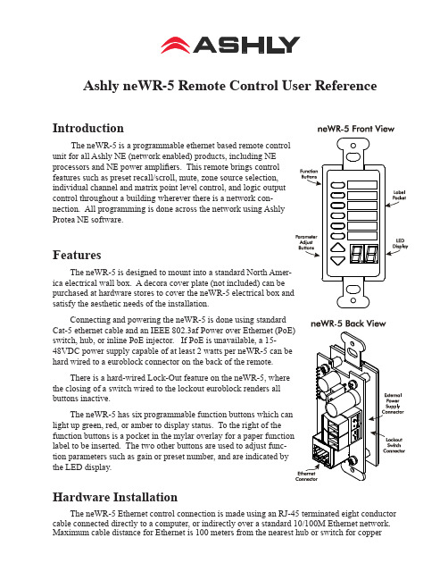
Ashly neWR-5 Remote Control User Reference Introduction The neWR-5 is a programmable ethernet based remote control unit for all Ashly NE (network enabled) products, including NE processors and NE power amplifiers. This remote brings control features such as preset recall/scroll, mute, zone source selection, individual channel and matrix point level control, and logic output control throughout a building wherever there is a network con-nection. All programming is done across the network using Ashly Protea NE software. FeaturesThe neWR-5 is designed to mount into a standard North Amer-ica electrical wall box. A decora cover plate (not included) can be satisfy the aesthetic needs of the installation.Connecting and powering the neWR-5 is done using standard switch, hub, or inline PoE injector. If PoE is unavailable, a 15-hard wired to a euroblock connector on the back of the remote.There is a hard-wired Lock-Out feature on the neWR-5, where the closing of a switch wired to the lockout euroblock renders all buttons inactive. light up green, red, or amber to display status. To the right of the label to be inserted. The two other buttons are used to adjust func-tion parameters such as gain or preset number, and are indicated by the LED display.Hardware InstallationThe neWR-5 Ethernet control connection is made using an RJ-45 terminated eight conductor cable connected directly to a computer, or indirectly over a standard 10/100M Ethernet network. Maximum cable distance for Ethernet is 100 meters from the nearest hub or switch for copper Operating Manual - neWR-5 Remote Control for NE Products2twisted pair CAT5 cable. If using PoE, no further power supply is required, otherwise connect a 15-48VDC power supply to the neWR-5 via the labelled is 38mA @48VDC.If desired, wire the Lock Out con-nector to an external remote or keyed switch.Upon connecting and powering up the system, the WR-5 will have a “heartbeat”, meaning an internal small green LED on the PCB (behind the display bezel) will be flashing. After power up, the LED displays “- -”. If there is a two-digit number showing in the display, that means the WR-5 has for that zone.Mount the neWR-5 to a wall box as shown (decora plate and wall box not included). Note: Avoid static shock disruptions to this or other connected devices by mounting the neWR-5 to an earth-grounded metal wall box, or by earth-grounding a metal decora plate. This prevents static discharge from flowing through the data lines.Protea NE SoftwareAshly NE products installed on the network will be automatically detected and displayed in the active device menu tree on the left side of the Protea NE software startup screen. The software scans for active NE devices every time it loads, but the user can manually scan at any time as well with <Scan For Devices> at the bottom of the network NE device listing. All NE devices continu-ously broadcast their availability to the software. All currently connected and active NE products are highlighted in green, while NE products which have been formerly installed but are currently off-line or unavailable show up in red. Individual NE products can be dragged onto the project canvas to simulate physical installation groups, but editing each product can be done from either the menu tree or the project canvas. Lines, rectangles, text, and image files can be added to create a custom virtual control screen along with NE products and individual control objects. To see all available canvas tools, right click anywhere over open canvas. Projects, including all device settings and canvas drawings, can be saved as a file. Checking <Design Mode> (right-click on canvas) allows placed objects to be moved around, while unchecking <Design Mode> locks objects in place. Once an image has been placed on the canvas, it must be deleted by hand if that device is no longer available to the software. Scanning for devices does not automatically remove images which may have been installed at one time but are now off line. To clear the canvas of all devices and drawn elements click <File - New>. Further neWR-5 help is available in Protea NE software by navigating through the online help menu.Operating Manual - neWR-5 Remote Control for NE ProductsMain Control SurfaceThe main control surface is where the neWR-5 is named, its target NE device gets selected, any zone definition occurs, and where the function buttons are programmed, The neWR-5 comes with all function buttons set to “Off”. Unlike the WR-5, changes must be saved to the neWR-5 before becoming effective. Not all of the button functions listed below are available on all NE products, for instance an amplifier will not have “matrix mixer” capability unless it has DSP installed, and some products do not have logic outputs. Protea NE software is able to determine which functions are available for neWR-5 control.1) Off - No function assigned and the button’s LED remains unlit2) Preset Recall - A single preset number is assigned to a button. When the button is pressed, the recalled preset number and the letters “PC” (Preset Change) are alternately flashed on the WR-5 for five seconds, also locking out any other WR-5 action for that time.3) Preset Scroll Mode - A range of presets can be assigned to a function button which when selected, enables the up/down buttons to scroll through the available presets. Upon release of the up/ down button, the currently displayed preset will load. The function button will glow amber for the duration of the preset scroll operation.4) Gain Control - Since there are many possible gain adjustment points within a given NE au-dio processing device, the neWR-5 displayed gain level is only a relative value. In other words, gain could be changed elsewhere in the target unit, independent from neWR-5 control. The neWR-5 can adjust gain from 0 to 99, and an upper and lower number limit can be set in the function range sec-tion to limit the maximum and minimum reach of that control. To control the gain within the target device’s input or output signal path, the neWR-5 remote gain function must first be inserted into a block in the unit’s DSP controls window.Gain Control over individual channel(s) - When a gain control button is assigned to control one or more individual channels, pressing that button will cause it to light amber, during which time the up/down buttons determine gain for the selected channels. If the up/down buttons remain idle for five seconds, the gain button becomes inactive until being pressed again. Gain Control over zone - If a zone output is active for that neWR-5, meaning one or more output checkboxes are selected within the neWR-5 Zone Setup mode, the output gain for that zone will be shown as the default numerical display, during which time the up/down buttons stay ac-tive for that zone’s overall gain control. If a button is assigned for individual input channel(s) gain control in addition to the neWR-5 being defined for output zone control, that button will turn amber when pressed, and both the neWR-5 up/down buttons and display will reflect the input channel(s) gain, reverting back to output zone gain after five seconds of inactivity. If there is no zone output assigned for the neWR-5, the display shows “--” as the default.5) Channel Engage/Mute - A button can be configured to mute one or more inputs or outputs, or any combination of the two. The button is green when engaged and red when the selected chan-nels are muted.3Operating Manual - neWR-5 Remote Control for NE Products6) Zone Source Selection - This function is used to assign a button to select one or more inputs for the defined zone (Select Zone Outputs) under neWR-5 control. Any function button can have any combination of inputs as sources. A zone source selection button is green when selected, and red when unselected. When multiple zone source select buttons are assigned different or over-lapping inputs, each button will simply add to or subtract from the other’s input selections. How-ever, if the Exclusive Source Selection box is checked in the zone setup, only the currently selected button’s inputs will be used for that zone.The <Disable Zone Level Control> checkbox allows input source selections to be changed from the neWR-5, but not the overall output gain for that zone. The output gain can still be adjusted from the target device software, but the neWR-5 user is locked out from making output zone gain changes.7) Logic Output Active High - This allows the user to toggle the Logic Output assigned pin to the button. The switch turns green when the output is high.8) Logic Output Active Low - The switch turns green when the output is Low.9) Matrix Mixer - This is used to select one or more inputs for the zone under neWR-5 con-trol, but allows level control of that group at the dsp matrix mixer point instead of the output. Select one or more Zone Output(s) in the Zone Setup to use the Matrix Mixer functionSecurityIn addition to the hardware lockout available on the neWR-5, there are multiple user/multiple levels of software protection assignable to the neWR-5 within the Security tab, from full access to view only. The security data is stored within the neWR-5 itself, not Protea NE Software. Passwords are case sensitive . Be sure to write down the password and store in a convenient place for future reference. Network PropertiesHardware, device, and device network configuration details are displayed in the network prop-erties tab. This includes the current neWR-5 firmware revision.Flash ReprogramThe firmware, meaning the internal program which runs on the neWR-5, can be updated easily over the network. Look in network properties for the current firmware revision. To obtain the latest firmware, visit the Ashly Web site, locate and save it to the computer, then run <Flash Reprogram> under the Device Options menu. The LED displays “Pr” during the reprogramming process.Factory ResetTo restore factory default settings, a factory reset can be performed by connecting power to the unit while holding the top function button down for 10 seconds, during which time a countdown will occur on the LED display. Releasing the button at any time prior to completion of the countdown stops the process. Upon completion of the countdown, the LED displays “Fr” until the neWR-5 is reset.2011 by Ashly Audio Corporation. All rights reserved worldwide.Printed in USA 0111 R1Ashly Audio Inc 847 Holt Rd Webster NY 14580585-872-0010 toll free 800-828-6308 fax 585-872-0739 。
ASHLY C面板手动操作使用说明
ASHLLY 4.24C24BitDigitalCrossover and System processor 手动操作使用说明目录一介绍 (1)二参数设置 (2)1 功能键和数据调节旋钮 (3)2 预置 (4)2.1 (操作一:如何储存预置) (4)3 输入通路选择 (5)3.1 (操作二:输入通路设置) (5)4 输出通路设置 (5)4.1(操作三:输出通路的选择) (6)4.2 (操作四:参数选择设置的操作) (6)4.3 举例 (7)4.3.1 如何设置EQ的参数 (7)4.3.2 如何设置DELAY (8)4.3.3 如何设置CROSSOVER (9)4.3.4 如何设置LIMITER (10)4.3.5 如何设置起始时间(A__ms) (10)和恢复时间 (R__ms)5 COPY设置的操作方法 (11)6 Mute设置方法 (11)7 Util设置方法 (12)7.1 如何选择full access和full lockout (13)7.2 如何去除密码 (14)7.3 dBu/VU 表选择 (14)7.4 MIDI 通路选择 (15)7.5 工厂设置(如何恢复清除所有预置的名字, (15)恢复工厂设置)一介绍Protea System Ⅱ 4.24C 数字分频器/系统处理器具有与用户界面耦合的4个输入和8个输出,以及作为一个精确的分频器和声音控制系统所要求的全部音频信号处理工具。
使用简单方便,甚至无需人工操控。
可以控制每一输入的增益、延时、和6个滤波器(你可将每个滤波器设置为参数式滤波器或高、低通滤波器)。
可以设置每一输出得分频频率和指定任一输入或任意输入的组合。
此外,还可以通过编程控制4个滤波器(你可将每个滤波器选择为参数式滤波器或高、通滤波器)、调节延时时间和输出增益、反相、控制压缩器/均衡器以保护扬声器系统。
本处理器的外形尺寸为1标准机构空间,输入输出为XLR型连接器。
当然,你也可以通过Ashlly的Protea System Software(Windows 95、98、2000和NT平台)、MIDI或SIA-Smaart 软件进行编程和控制。
Xalz参考手册李
MarcoXalz电液控制软件用户参考手册编篡:北京天地玛珂电液控制系统有限公司二00一.十目录一对话框入门 (6)二服务对话框 (12)三设置对话框 (22)四控制对话框 (32)五诊断对话框 (55)六统计对话框 (65)七图形对话框 (69)八SCU对话框 (79)九帮助对话框 (90)十图形界面的对话框 (93)十一术语解释 (101)一对话框入门目录1. 激活开采方式2. 启动开采方式3. 执行功能4. 手动推溜5. 图形管理1. 激活开采方式打开对话框通过点击主窗口“控制”区,“控制”栏下,显示(“---”,“增量”“增量+自动移架”)的按钮,打开本对话框。
对话框窗口图对话框功能激活的开采方式在对话框上部显示。
当选择“增量”开采方式时,可以移动基线,并可打开或关闭基线自动移进,而且可以停止当前激活的开采方法或者在帮助提示下选择新方法。
对话框说明开采方式显示激话的开采方式,模式可在另一个对话框中改变(点击“选择”按钮)。
如果没有激活的开采方法,显示“---”。
基线按下标有方向键头按钮可以前移或后移基线位置,向上键头表示前移,向下键头表示后移。
单键头表示每按一下移进一步。
双键头表示移动10倍移动步距。
从机头到机尾可以设置不同的步进距,通过手工干预,这个步距决定于当前位置和基线位置,系统认为采煤机将朝更大面部分的方向移动。
如果选择传统模式,基线设置是无效的。
自动移进这里可以打开或关闭基线的自动移进,如果打开,基线将自动前移。
开采方式这里可以按下“停止”按钮停止开采方法,“选择”按钮选择新的开采方法。
清除运行当方式是“增量”或“增量+自动移架”时,这里可以调整采煤机是否做清除运行。
打开按下进行清除运行,当前采煤机运行时不推溜。
关闭关闭清除运行,采煤机运行时正常推溜。
2.启动开采方式打开对话框如果在上述对话中选中“选择”按钮,弹出本对话框。
对话框窗口图对话框功能在此对话框中,可以开始预期的自动模式。
ASI控制工具用户手册0
AS-I 控制工具用户手册目录1 使用的符号 ----- -------------------------------------------- 32 特性 ---- --------------------------------------------- 33 最初的步骤 ---- --------------------------------------------- 33.1 系统需求3.2 软件安装3.3 软件注册3.4 帮助3.5 与AS-i 主控制器建立通信3.6 进入AS-i 运行状态3.7 使用AS-I 配置文件(*.acg)工作控制程序 ----- -------------------------------------------- 5 4 AS-i4.1 创建一个AS-i控制程序4.2 A S-i控制演示程序4.3 第一个AS-i控制程序5 菜单File… -------------------------------------------- 85.1 File…New5.2 File…Open5.3 File…Close5.4 File…SaveAs5.5 File…Save5.6 File…Print5.7 File…Print Preview…5.8 File…Print Setup…5.9 File…1,2,3,45.10 File (xi)6 菜单Edit… -------------------------------------------- 116.1 Edit…Undo6.2 Edit…Cut6.3 Edit…Copy6.4 Edit…Paste6.5 Edit…DeleteAll6.6 Edit…Select6.7 Edit…Find…6.8 Edit…Find Next6.9 Edit…Replace…6.10 Edit…Goto…7 菜单Program Control… -------------------------------------- 127.1 Program Control…Execute7.2 Program Control…Debug7.3 Program Control…Simulate7.4 Program Control…Upload7.5 Program Control…Download7.6 Program Control…Syntax Check7.7 Program Control…Compile7.8 Program Control…Start7.9 Program Control…Stop7.10 Program Control…Pause8 菜单Master… -------------------------------------------- 158.1 Master…New…8.2 Master…Identity8.3 Dialog Offline on Configuration Error…8.4 Dialog AS-i Control Properties…8.5 Master…AS-i Configuration ------------------------------- 17 8.6 Master…AS-i Configuration Editor(Textual Display)8.7 Master…AS-i Configuration Editor(Grafical Display)8.8 Dialog Master Configuration…8.9 Dialog Slave Configuration…8.10 Dialog Device Description… -------------------------------- 20 8.11 Dialog Store Configuration8.12 Master…AS-i Diagnosis8.13 Dialog Deblock AS-i Diagnosis…8.14 Master…AS-i Address Assistant8.15 Master…Insert AS-i Slave8.16 Master…Write Configuration to the AS-i Master…8.17 Master…Save Configuration to File…8.18 Master…Offline8.19 Master…Recent Master9 菜单Extras… -------------------------------------------- 239.1 Extra…GSD Wizard…10 菜单View… -------------------------------------------- 2310.1 View…Toolbar10.2 View…Statusbar10.3 View…Font10.4 View…Grafical Display11 Window… -------------------------------------------- 2611.1 Window…New Window11.2 Window…Cascade11.3 Window…Tile11.4 Window…Arrange Icons11.5 Monitor Windows11.6 Window…Input Monitor11.7 Window…Output Monitor11.8 Window…Flag Monitor11.9 Window…Timer Monitor11.10 Window…Counter Monitor11.11 Window…Output Log11.12 Window…1,2,…12 菜单Help -------------------------------------------- 2812.1 Help…Index12.2 Help…Using Help12.3 Registration12.4 Help…Info12.5 Context Help…AS-i 控制工具(1-7由钱昀翻译, 高晋占校)1 使用的符号这个符号警告用户可能的危险。
美国ASHLY424中文说明书
美国ASHLY 4.24C数字式处理器操作手册美国[雅士利]ASHL Y 4.24C数字式处理器的操作方式有两种:一为通过电脑与4.24C联机后,在电脑上调整处理器内各项参数;一为通过机器面板上的按键更改处理器的各项参数。
第一种方式相对比较方便技术人员的操作。
技术人员需要使用RS-232线连接电脑的串口和4.24C主机前面板的RS-232端口。
打开电脑中Protea System Software软件(最新版本是6.13),点击主菜单中Devices选4.24C Crossover,接着点击主菜单中Communications,点击commport assignment选好电脑的com口,接着点击Enable Communications就可以与主机相连了。
上图是软件的操作界面。
软件界面上半部分左面的A、B、C、D是输入端,有哑音(Mute)、延时(Delay)、增益(Gain)、均衡(EQ)四个信号处理模块。
软件界面上半部分右面的1-8是输出端,有路由(Routing)、高通低通(HpfLpf)、均衡(EQ)、延时(Delay)、增益(Gain)、限幅(Limiter)、哑音(Mute)七个信号处理模块。
当要对音频信号作处理时,只要鼠标点击信号处理模块,软件界面的下半部分就显示所点击的信号处理模块的内容。
如上图中鼠标点击了输出1的高通低通模块,该模块变成黄色的显示,软件界面下半部分就是高通低通频点的设置界面。
当所有设置完成之后,点击主菜单中File,再点击Save Present to Protea…即可把设定写入4.24C主机内,并可以在30个预设位置中选择所要记录的位置及更改预设的名字。
第二种方式是通过前面板的按键调整各处理模块的参数。
这种方式主要用于流动系统安装后之后对系统作细微调整。
上图是4.24C主机前面板。
最左面是RS-232控制端口。
接着是4个输入通道的电平表及白色的通道选择键。
- 1、下载文档前请自行甄别文档内容的完整性,平台不提供额外的编辑、内容补充、找答案等附加服务。
- 2、"仅部分预览"的文档,不可在线预览部分如存在完整性等问题,可反馈申请退款(可完整预览的文档不适用该条件!)。
- 3、如文档侵犯您的权益,请联系客服反馈,我们会尽快为您处理(人工客服工作时间:9:00-18:30)。
此版本目前只做内部参考用(最终细节均以ASHLY 英文原版参考手册为准翻译/编写:ONLY.CHENG Protea System Software 软件控制说明(ASHLY Protea 4.24C)硬件名称:ASHLY Protea 4.24C软件名称:Protea System Software软件版本:5.0语言环境:英语系统平台:WIN95/98/2000/NT简单介绍:ASHLY Protea 4.24C是ASHLY 公司出品的数字式分频器/系统处理器,具有4 个输入,8个输出;占用1U机架空间;可以任意分配输入至输出;具有分频、均衡、延时和限幅等功能;具有LINKWITZ-RILEY、BESSEL和BUTTERWORTH 滤波器;滤波器斜率分别为12、18、24、48dB/倍频程;参数式均衡器;带通、1/64 至4 倍频程范围;输入和输出延时;每一输出均具有限幅器;直观的用户界面;通过PC 或MIDI 进行控制;AMX 兼容网络链接控制;专门的输入和输出电平表;平衡式输入和输出;XLR 信号连结器;双重安全保护设置;使用简单方便,设定好之后,甚至无需人工操控,简洁精致的电路设计,保证了它能够实现无忧、高性能的工作。
与其它同类产品相比较,它的体积小巧,重量更轻,音质细腻,PC 控制软件使用方便,操作灵活,高级的音质和效果,大众化的价钱,正是这些特点,使它适用于专业录音棚、电台、舞台上、剧院里、餐馆、俱乐部、酒吧、旅馆、商场、健身室、保龄球场以至户外的游乐场、火车站、体育场馆等……甚至音乐家的家里……所以它能够广泛的用在固定安装和现场扩声系统中,受到了众多专家和用户的一致好评,本说明主要介绍怎样通过软件对ASHLY Protea 4.24C进行设定,是您对ASHLY Protea 4.24C以及它的PC控制软件Protea System Software有一个基本的了解。
ASHLY Protea 4.24C 技术特性:输入:有源平衡式,18KΩ阻抗最大输入电平:+20dBu输出:有源平衡式,100Ω阻抗最大输出电平:+20dBu频率响应:±2.5dB,20Hz-20kHz总谐波失真:<0.01%@1kHz, +20dBu动态范围:>110dB(20-20kHz),不计权输出噪声:<-90dBu, 不计权EQ 滤波器:数量:6 个/输入,4 个/输出参数式带宽:1/64 至4 倍频程范围:+15/-30dB,0.1dB步进值频率间隔:1/24 倍频程高通滤波器斜率:6 或12dB/备频程可选此版本目前只做内部参考用(最终细节均以ASHLY 英文原版参考手册为准翻译/编写:ONLY.CHENG频率范围:19.7Hz-20kHz范围:+15,0.1dB步进值低通滤波器斜率:6 或12dB/备频程可选频率范围:3.1886kHz-20.1587kHz范围:+15,0.1dB步进值分频滤波器高通滤波器类型:linkwitz-riley,Bessel,butterworth斜率:12/18/24/48 倍频程频率范围:0-21.9833kHz,245 步进值低通滤波器类型:linkwitz-riley,Bessel,butterworth斜率:12/18/24 倍频程频率范围:0-21.9833kHz,245 步进值延时输入最大延时:682.5ms输出最大延时:21.33ms步进值:20μs输入和输出增益范围:+12/-40dB,0.1dB步进值极性:0゜或180゜压缩器/限幅器门阈:-20dBu-20dBu 1dB步进值压缩比:1.2:1-∞(1.2,1.5,2,3,4,6,10,20, ∞:1)上冲时间:0.5ms-50ms/dB释放时间:10ms-1s/dB范围:20Hz-10.6kHz处理器输入模/数转换:24bit输出数/模转换:24bit处理器:24bit,56bit存储器采样率:48kHz信号延时:1.46ms其它电源要求:80-260VAC,30W包装重量:10 磅尺寸:19”x1.75”x6.0”(宽x 高x 深)输入输出连接器:XLR环境温度:40-120゜F控制方式protea system software(windows tm95、98、2000 和NT平台)、MIDI或SIA-Smaart软件进行编程和控制。
还可以通过AMX Netlink System(AMX 网络链接系统)进行控制。
此版本目前只做内部参考用(最终细节均以ASHLY 英文原版参考手册为准翻译/编写:ONLY.CHENG 软件安装首先在PC机上进行软件的安装,软件名称是Protea System Software,在随机的光碟中可以得到,或者到进行下载,目前的版本是Protea System Software 5.0。
具体的安装步骤在这里不作介绍。
进行默认安装,安装好之后,运行开始菜单/程序/Ashly Audio Inc/ Protea System Software 5.0。
(图1.1.1)是打开程序后的主界面。
图1.1.1联机方法:1.使用附带的串口线,连接PC机的RS232端口到ASHLY Protea 4.24C的RS232端口。
打开Protea System Software 5.0 软件,首先选择主菜单Communications/comport Assignment…….(图1.1.2)。
此版本目前只做内部参考用(最终细节均以ASHLY 英文原版参考手册为准翻译/编写:ONLY.CHENG (图1.1.2)2.在打开的对话框中,选择您联接的PC机端口名称,选择好之后,点击OK。
(图1.1.3)(图1.1.3)3.选择Communications/enable Communications,显示已联机,并且软件主界面显示出当前ASHLYProtea 4.24C的路由、分频、延时和均衡等状态。
4.联机成功程序界面介绍:进行正确的联机操作后,打开Protea System Software 5.0,在Protea System Software 5.0主程序界面上,像WINDOWS平台上运行的所有窗口式程序一样(例如WINDOWS写字板),上面是主菜单,分别是file(文件)、edit(编辑)、communications(通信)、devices(设备)、mute(哑音)、options(设置)、security(安全)、help(帮助)和exit(退出)。
下面是1到16,注意:在进行联机操作时,请使用附带的串口线,连接PC 机的RS232 端口到ASHLY 4.24C 的RS232端口;也可以在不联机的情况下,在Protea System Software 5.0 中,进行路由、分频、延时和均衡等设定,设定好之后,存储在PC 机上,以便在下次联机时,将设置文件上传到ASHLY 4.24C上,设置文件的后缀名为PCC。
此版本目前只做内部参考用(最终细节均以ASHLY 英文原版参考手册为准翻译/编写:ONLY.CHENG 16 个方便切换的设置。
再下面可以很直观的看到,4路输入,每一输入通道都具有mute(哑音)、delay(延时)、gain(增益)和EQ(均衡)等功能;8 路输出,每一输出通道都具有routing(路由)、hpflpf(高低通)、EQ(均衡)、delay(延时)、gain(增益)、limiter(限幅)和mute (哑音)等功能。
再下面是针对每一项具体功能的具体显示窗口。
菜单介绍:file菜单:(图1.1.4)Enter/edit preset name…用来修改16 个预置的名称Save preset to disk…将设置以后缀名ppc保存到硬盘上Save preset to protea…将设置上传到ashly Protea 4.24C上Recall preset from disk…从硬盘读出后缀名为ppc的设置文件Recall preset from protea…从ashlyProtea 4.24C(4.24d、vcm88 等)上下载设置到软件中Download midi dump to protea…从midi 接口上传设置到ashlyProtea 4.24C上。
Trigger midi dump from protea…利用midi 接口从ashlyProtea 4.24C上得到设置。
print channel 打印设置(图1.1.4)edit菜单:(图1.1.5)copy input 复制输入通道的delay(延时)、gain(增益)和EQ(均衡)三项设置到剪贴板paste input从剪贴板粘贴输入通道的delay(延时)、gain(增益)和EQ(均衡)三项设置到本通道copy output 复制输出通道的routing(路由)、hpflpf(高低通)、EQ(均衡)、delay(延时)、gain(增益)、limiter(限幅)五项设置到剪贴板paste output从剪贴板粘贴输出通道的hpflpf(高低通)、EQ(均衡)、delay(延时)、gain (增益)、limiter(限幅)五项设置到本通道此版本目前只做内部参考用(最终细节均以ASHLY 英文原版参考手册为准翻译/编写:ONLY.CHENG (图1.1.5)communications 菜单:(图1.1.6)Enable communications 允许联机Disable communications 禁止联机Commport assignment…指定PC链接到ASHLY Protea 4.24C所使用的串口号。
(图1.1.6)devices 菜单:(图1.1.7)Protea 4.24C选择设备型号为ashly Protea 4.24C4.24D 选择设备型号为ashly 4.24DGraphic EQ 选择设备型号为ashly Grapic EQ此版本目前只做内部参考用(最终细节均以ASHLY 英文原版参考手册为准翻译/编写:ONLY.CHENG Parametric EQ 选择设备型号为ashly Parametric EQVcm-88 选择设备型号为ashly Vcm-88(图1.1.7)mute菜单:(_______图1.1.8)Mute all outputs 哑音所有输出通道Unmute all outputs 所有输出通道取消哑音(图1.1.8)opintions /configuration菜单:(图1.1.9)4x2-way crossover 4 输入4 立体声输出配置(图1.1.9.1)2x3-way,and 2 aux 2 输入6 输出加2 辅助输出配置(图1.1.9.2)2x3-way+mono sub 2 输入6 输出加单声道超低音输出配置(图1.1.9.3)2x4-way crossover 2 输入8 输出配置(图1.1.9.4)1x5-way,and 3 aux 1 输入5 输出加3 辅助输出配置(图1.1.9.5)mono distribution 4 输入混合成单声道8 输出配置(图1.1.9.6)stereo distribution 4 输入(前2 路混合,后2 路混合)4 立体声输出配置(图1.1.9.7)此版本目前只做内部参考用(最终细节均以ASHLY 英文原版参考手册为准翻译/编写:ONLY.CHENG LCRS with mono subs左、中、右、环绕加单声道超低音配置(图1.1.9.8)4x4 processor 4 输入4 输出配置(图1.1.9.9)Muted, flat startup 输入、输出全部静音,没有任何输入路由到输出配置,称作预备模式(图1.1.9.10)(图1.1.9)(图1.1.9.1)此版本目前只做内部参考用(最终细节均以ASHLY 英文原版参考手册为准翻译/编写:ONLY.CHENG (图1.1.9.2)(图1.1.9.3)此版本目前只做内部参考用(最终细节均以ASHLY 英文原版参考手册为准翻译/编写:ONLY.CHENG (图1.1.9.4)(图1.1.9.5)此版本目前只做内部参考用(最终细节均以ASHLY 英文原版参考手册为准翻译/编写:ONLY.CHENG (图1.1.9.6)(图1.1.9.7)此版本目前只做内部参考用(最终细节均以ASHLY 英文原版参考手册为准翻译/编写:ONLY.CHENG (图1.1.9.8)(图1.1.9.9)此版本目前只做内部参考用(最终细节均以ASHLY 英文原版参考手册为准翻译/编写:ONLY.CHENG (图1.1.9.10)opintions /metering菜单:(图1.1.10)(图1.1.10)dBu meters(图1.1.11) dBu电平表此版本目前只做内部参考用(最终细节均以ASHLY 英文原版参考手册为准翻译/编写:ONLY.CHENG (图1.1.11)VU meters(图1.1.12) VU电平表(图1.1.12)security菜单:(图1.1.13)password 可以设定或修改预置的密码以下三项对于不同的ASHLY 设备有所不同,这里仅介绍Protea 4.24C。