ANSYS结构仿真应用介绍
ansys workbench建模仿真技术及实例详解 -回复
ansys workbench建模仿真技术及实例详解-回复题目:ANSYS Workbench建模仿真技术及实例详解引言:ANSYS Workbench是一种强大的工程仿真软件,广泛应用于各个领域的工程设计和分析中。
本文将以ANSYS Workbench建模仿真技术为主题,详细介绍其基本原理、建模方法和实例应用,帮助读者更好地了解和掌握这一工具的使用。
第一部分:ANSYS Workbench基本原理1. ANSYS Workbench简介:介绍ANSYS Workbench的功能和应用领域。
2. ANSYS Workbench的工作流程:详细解释ANSYS Workbench的工作流程和各个模块的作用。
第二部分:ANSYS Workbench建模技术1. 几何建模:介绍ANSYS Workbench中的几何建模工具,包括创建基本几何图形、引入外部几何文件和几何修剪等操作。
2. 材料属性定义:讲解如何设置材料属性,并介绍常用的材料模型和参数的选取。
3. 网格划分:介绍ANSYS Workbench中的网格划分方法,包括自动划分和手动划分两种方式,并讲解网格质量的评估和改善方法。
4. 边界条件设置:讨论各种边界条件的设置方法,如固定边界条件、加载边界条件和对称边界条件等。
5. 求解器选择与设置:介绍ANSYS Workbench中常用的求解器选择和设置方法,包括静态求解和动态求解两种模拟方法,并讨论参数对求解结果的影响。
6. 后处理与结果分析:讲解ANSYS Workbench中的后处理工具的使用方法,包括结果显示、变量提取和结果比较等。
第三部分:ANSYS Workbench建模仿真实例1. 结构力学仿真实例:以某一结构件为例,详细介绍ANSYS Workbench 如何进行结构力学仿真分析,并分析结果。
2. 流体力学仿真实例:以某一管道流体流动为例,介绍ANSYS Workbench如何进行流体力学仿真分析,分析流体流动特性。
学会使用ANSYS进行工程仿真分析
学会使用ANSYS进行工程仿真分析第一章:ANSYS工程仿真分析的基础知识ANSYS是目前世界上广泛使用的一种工程仿真分析软件,它可以用于各种不同领域的工程分析和设计。
熟练掌握ANSYS的使用方法对于工程师来说至关重要。
本章将介绍ANSYS的基础知识,包括软件的安装和启动、用户界面的介绍以及基本操作方法等。
首先,安装ANSYS软件是使用它的前提。
用户可以从ANSYS 官方网站上下载安装文件,并按照安装向导的步骤进行安装。
安装完成后,可以通过点击桌面上的图标来启动ANSYS。
启动后,会出现ANSYS的用户界面。
用户界面通常由菜单栏、工具栏、主窗口和命令窗口等组成。
菜单栏上包含了各种功能的菜单,用户可以通过点击菜单来选择所需的功能。
工具栏上则包含了一些常用的工具按钮,可以方便地进行操作。
主窗口用于显示分析结果和编辑模型等。
命令窗口则用于输入命令进行操作,这在一些高级功能中会用到。
在进行工程仿真分析之前,需要先创建一个模型。
ANSYS提供了多种建模工具,例如几何建模工具和计算网格生成工具等。
可以根据需要选择合适的建模工具,并按照提示进行操作。
在建模完成后,可以对模型进行网格生成,即将模型划分为小块,并计算各个小块上的分析参数。
第二章:结构分析结构分析是ANSYS中的一个重要模块,用于对各种结构件进行强度、刚度和模态等分析。
本章将介绍ANSYS中常用的结构分析方法和技巧。
在进行结构分析之前,需要先定义结构的边界条件和加载条件。
边界条件包括约束条件和支撑条件等,而加载条件则包括外力和内力等。
用户可以通过ANSYS提供的工具来定义这些条件,并将其应用于模型中。
在进行结构分析时,可以选择合适的分析方法。
ANSYS提供了多种分析方法,例如静力分析、动力分析和模态分析等。
用户可以根据具体的分析要求选择合适的方法,并设置相应的分析参数。
在进行结构分析时,还可以使用ANSYS的后处理功能来查看分析结果。
后处理功能可以用于绘制应力云图、位移云图和动力响应曲线等。
ansys workbench建模仿真技术及实例详解 -回复
ansys workbench建模仿真技术及实例详解-回复什么是ANSYS Workbench建模仿真技术,以及提供一个实例来详解。
ANSYS Workbench建模仿真技术是一种集成在ANSYS软件平台下的先进仿真建模工具。
它能够提供全面的、高精度的仿真分析,用于解决各种工程问题。
ANSYS Workbench能够模拟并分析结构力学、流体动力学、热传导和电磁场等各种物理现象,它是一个功能强大且灵活的工具,可用于设计优化、性能评估和故障诊断等应用。
ANSYS Workbench的优势之一是其集成的工作环境。
它提供了一个统一的界面,允许工程师能够轻松地建立多物理场的模型、设置边界条件、进行网格划分以及执行仿真分析。
这个集成环境大大提高了工作效率,减少了因为转换格式而产生的错误和不一致性。
ANSYS Workbench还具有高度可扩展性。
它支持多种不同类型的分析,并且可以与其他工具和软件集成。
这使得工程师能够根据他们的特定需求,选择合适的分析方法和模型。
此外,ANSYS Workbench还可以通过添加插件和自定义脚本等方式进行扩展和定制化,以满足用户需求。
下面以一个实例来详细说明ANSYS Workbench建模仿真技术的应用。
假设我们要设计一个汽车的底盘,我们希望通过仿真分析来优化其刚度和强度。
首先,我们需要建立一个底盘的三维几何模型。
可以使用ANSYS SpaceClaim软件来创建几何模型,然后将其导入到ANSYS Workbench 中进行后续分析。
接下来,我们需要定义材料属性。
通过在材料库中选择合适的材料,并输入相应的力学参数,如弹性模量、泊松比和屈服强度等。
这些参数将用于定义底盘的材料行为。
然后,我们需要设定边界条件。
我们可以设定车轮的载荷、车身的支撑条件、底盘的连接方式等。
这些边界条件将用于约束和模拟底盘在实际工况下的受力情况。
接着,我们需要对几何模型进行网格划分。
ANSYS Workbench提供了多种网格划分工具,可以根据模型的复杂性和分析需求选择合适的网格类型和划分方法。
基于ANSYS的刚性导轨结构动态仿真说明书
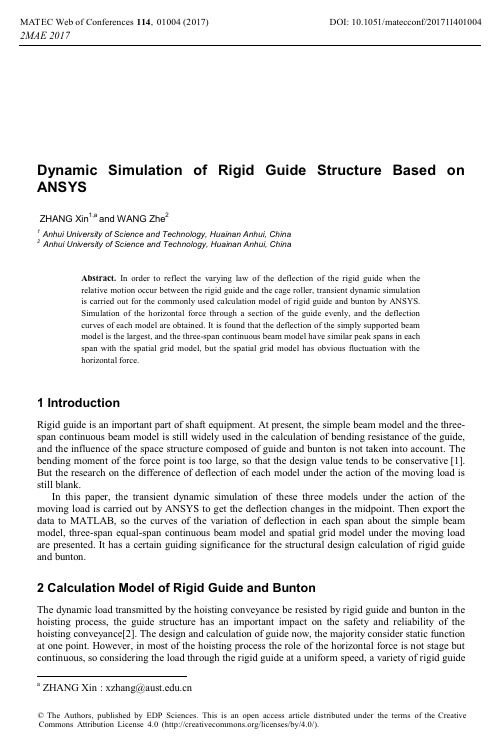
Dynam i c S i mulat i on of R i g i d Gu i de Structure Based on ANSYSZHANG Xin1,a and WANG Zhe21Anhui University of Science and Technology, Huainan Anhui, China2Anhui University of Science and Technology, Huainan Anhui, ChinaAbstract. In order to reflect the varying law of the deflection of the rigid guide when therelative motion occur between the rigid guide and the cage roller, transient dynamic simulationis carried out for the commonly used calculation model of rigid guide and bunton by ANSYS.Simulation of the horizontal force through a section of the guide evenly, and the deflectioncurves of each model are obtained. It is found that the deflection of the simply supported beammodel is the largest, and the three-span continuous beam model have similar peak spans in eachspan with the spatial grid model, but the spatial grid model has obvious fluctuation with thehorizontal force.1 IntroductionRigid guide is an important part of shaft equipment. At present, the simple beam model and the three-span continuous beam model is still widely used in the calculation of bending resistance of the guide, and the influence of the space structure composed of guide and bunton is not taken into account. The bending moment of the force point is too large, so that the design value tends to be conservative[1]. But the research on the difference of deflection of each model under the action of the moving load is still blank.In this paper, the transient dynamic simulation of these three models under the action of the moving load is carried out by ANSYS to get the deflection changes in the midpoint. Then export the data to MATLAB, so the curves of the variation of deflection in each span about the simple beam model, three-span equal-span continuous beam model and spatial grid model under the moving load are presented. It has a certain guiding significance for the structural design calculation of rigid guide and bunton.2 Calculation Model of Rigid Guide and BuntonThe dynamic load transmitted by the hoisting conveyance be resisted by rigid guide and bunton in the hoisting process, the guide structure has an important impact on the safety and reliability of the hoisting conveyance[2]. The design and calculation of guide now, the majority consider static function at one point. However, in most of the hoisting process the role of the horizontal force is not stage but continuous, so considering the load through the rigid guide at a uniform speed, a variety of rigid guide a ZHANGXin:***************.cndeflection curve calculation model is necessary. In the stage of uniform hoisting of the hoisting conveyance, it is assumed that the transverse horizontal force acting on the guide by the cage roller does not change, so the simply supported beam model, three-span continuous beam model and spatial grid model can be built in Figure 1. The force of the cage roller on the guide is simplified as a force perpendicular to the beam, the relative motion of the cage roller and the guide into a uniform translation is simplified as a force along the axis of the beam.Figure 1.Three Simulation Models.In the simple supported beam model, both ends of the guide are considered to be hinged; both ends of the three-span continuous beam model are considered to be hinged, and the middle two nodes are regarded as rigid contact3 Calculation of Mid-Span Deflection of ModelFor the maximum deflection of the simple beam model and the three-span continuous beam model, according to the mechanics of materials and the use of building structure statics to get its formula. In the simply supported beam model, the maximum deflection occurs when the load is applied to the mid-span nodes; in the three-span continuous beam model, the maximum deflection occurs when loads are applied to the three mid-span joints respectively[3].Equations of the maximum deflection of the simply supported beam model:इ௫=−ிయ(1)ସ଼ாூEquations of the maximum deflection of the three-span continuous beam model:इ௫=−ܭ×ிయ(2)ଵாூThe meaning of each parameter:• F is the force;• ݈is the length of the single-layer canal (ie, the distance between the canopy beam layer);• E is the elastic modulus of the material;• I is the section moment of inertia;• K is the maximum deflection calculation factor obtained by the look-up table.According to the actual data:F= 8000N݈= 4mE =2.06 × 10 MP(3)ܫ=ுయିయଵଶIn the mid-span of the first span and the third span in the three-span continuous beam:K = 1.458 (4) In the second span.:K = 1.146 (5) So the following data can be calculated:The maximum deflection of the simply supported beam model is:इ௫=−1.57mm(6) The maximum deflection of the three-span continuous beam is:The mid-span of the first and third span:इ௫=−1.12mm(7) The mid-span of the second span:इ௫=−0.86mm (8) However, it is not easy to calculate the deflection of each span in the spatial grid structure. In order to obtain the deflection of the spatial grid structure under the moving load, it is necessary to carry on the finite element simulation analysis.4 Finite Element Simulation Analysis4.1 Define MaterialsAccording to the design data of a mine, both sides of the guide are arranged in parallel. The length of the guide is 12 m, two guides are located 1.8 m apart, the length of the bunton is 4.86 m, the span of bunton is 4 m, the short beam length of the connecting guide and bunton in the spatial grid model is 0.1 m. Materials are Q235 cold-formed square steel, cross-sectional size of 180 × 180 × 10.According to the above data beam, the analysis model is established in ANSYS, set the modulus of elasticity for 2.06×10ହܯܲ, poisson's ratio is 0.3, the density is 7800kg/݉ଷ, choose the BEAM188 three-dimensional beam element.4.2 Meshing, Applying Constraints and LoadsThe size of the global control element is 0.1m, and the guide length 12m used to apply the load is divided into 120 elements with 121 nodes. For both ends of the hinge point, constrain the X, Y, Z direction of displacement; for the model of spatial grid structure, constrain the UX, UZ, RO TX, RO TY, RO TZ degrees of freedom of the short beam at the junction of the guide and the bunton; constrain the UX, UY, UZ degrees of freedom at both ends of the bunton. The spatial grid structure is shown in Figure 2. In this paper, we use the * DO loop to apply the load to the 121 nodes of the guide in order to simulate the relative motion between the guide and the cage roller by using the method of moving load in the vehicle-bridge analysis model[4-5].Figure 2.Spatial Grid Structure Model Meshing and Constraints.According to the data, the pre-tightening force of the Y direction of the cage roller is 8000N, the speed of the uniform speed is 8m/s. Assuming the uniform speed does not impact on the guide, defining the moving load P is 8000N, along the Y axis negative direction, and the moving speed is 8m / s, along the X axis positive direction.4.3 Simulation ResultsThe NSO L function is used to extract the displacement value of the Y direction of the simple supported beam, the displacement values of the three mid-span nodes in the Y direction of the three-span continuous beam model and the spatial grid model. Then export the data to MATLAB, take the time as the X axis, the displacement as the Y axis, draws the displacement - time curve, as shown inFigure 3Figure parison of Mid-Span Deflection of Each Model.5 Result AnalysisAccording to the simulation results, the maximum deflection values in each span of the simply supported beam model, three-span continuous beam model and spatial grid model are shown in Table 1.Table 1. Maximum deflection values in each span(mm).First Mid-span Second Mid-span Third Mid-spanSimulat -ion Theoret-icalDeviati-onSimulat-ionTheoret-icalDeviati-onSimulat-ionTheoret-icalDeviati-onSimplySupportedBeam-1.64-1.570.07Three-spanContinuousBeam-1.15-1.120.03-0.90-0.860.04-1.15-1.120.03Spatial GridModel-0.93-0.92-0.93It can be seen from Table 1 that when the calculation model of guide and bunton is calculated according to the simple supported beam, its mid-span deflection will be much larger than that of three-span continuous span beam and spatial grid model. So it is necessary to increase the cross-sectional area of the guide or the use of higher bending stiffness of the material, thereby increasing costs[6].At the same time,it can be seen from the table that the maximum deflection of the mid-span of the simple beam model and the three span continuous beam model are basically the same as the theoretical calculation result.The deflections of the three-span continuous beam model and the spatial grid model are similar at the maximum. However, according to the comparison of mid-span deflection curves, the mid-span deflection of the three-span continuous beam is relatively gentle, but the mid-span deflection of the spatial grid model is more violent, which is bound to produce vibration, impact on the stability of the guide structure6 Conclusion• Finite element simulation deviation within the allowable range. So the finite element method can be used to simulate the spatial structure of the guide structure;• The deflection of the simply supported beam model is much greater than that of the three-span continuous beam and spatial grid model. The maximum deflection in each span is similar to the three-span continuous beam model when calculated by the space grid model;• Compared with the three-span continuous beam model, when the space grid structure is used, the mid-span deflection of each span is more violent under the moving load. In the design calculation of the tank, to take into account this situation, to avoid fatigue damage.• Compared with the theoretical calculation, the finite element method is more consistent with the actual working conditions, especially for the analysis of complex moving loads, the use of finite element simulation can provide the necessary reference for the design and calculation. AcknowledgementsThis research was supported by the Key Project of Natural Science Foundation for Anhui University (No.KJ2015ZD019).References1.Wang Dongquan,Shi Tiansheng,Liu Zhiqiang and Guo Jinpu. Method for Calculating theStructure of Rigid Shaft Equipment of Deep Mine. Journ al of Chin a Un iversity of Min in g& Technology. 26(1):5̚8,(1997)2.Qin Qiang,QI Xiao-nan,Ding Jian-guo and Jian Hui. Analysis on Shaft Guide Equipment Quality.Coal Mine Machinery .36(6):168-170,(2015).3.Guo Zhenxi,Zhang Shuyi.Static Caculation Handbook for Practical Strucyure. China MachinePress. 4:320-322,(2009)4.Ge Junying. Analysis of Bridge Structure Based on ANSYS. China Railway Publishing House.8:150-156,(2007).5.SANMANI F S,PELLICANO F.Vibration reduction on beams subiected to moving loads usinglinear and nonlinear dynamic aborbers[J].Journal of Sound and Vibration. 325:742̚754,(2009) 6.Jiang Yuqiang. Research on Nonlinar Coupling Characteristcs and Condition Assessment ofVertical Steel Guide System. China University of Mining and Technology.(2011).。
ANSYS模态分析
ANSYS模态分析ANSYS模态分析是一种用于计算和研究结构的振动和模态的仿真方法。
它可以帮助工程师和设计师了解结构在自由振动模态下的响应,从而优化设计和改进结构的性能。
本文将对ANSYS模态分析的原理和应用进行详细介绍。
ANSYS模态分析基于动力学理论和有限元分析。
在模态分析中,结构被建模为一个连续的弹性体,通过求解结构的固有频率和模态形状来研究其振动行为。
固有频率是结构在没有外力作用下自由振动的频率,而模态形状则是结构在每个固有频率下的振动形态。
模态分析可以帮助工程师了解结构在特定频率下的振动行为。
通过分析结构的固有频率,可以评估结构的动态稳定性。
如果结构的固有频率与外部激励频率非常接近,可能会导致共振现象,从而对结构造成破坏。
此外,模态分析还可以帮助识别结构的振动模态,并评估可能的振动问题和改进设计。
1.准备工作:首先,需要创建结构的几何模型,并进行必要的网格划分。
在几何模型上设置适当的约束条件和边界条件。
选择合适的材料属性和材料模型。
然后设置分析类型为模态分析。
2.计算固有频率:在模态分析中,需要计算结构的固有频率。
通过求解结构的特征值问题,可以得到结构的固有频率和模态形状。
通常使用特征值求解器来求解特征值问题。
3.分析结果:一旦得到结构的固有频率和模态形状,可以进行进一步的分析和评估。
在ANSYS中,可以通过模态形状的可视化来观察结构的振动模态。
此外,还可以对模态形状进行分析,如计算应力、变形和应变等。
ANSYS模态分析在许多领域都有广泛的应用。
在航空航天工程中,模态分析可以用于评估飞机结构的稳定性和航空器的振动特性。
在汽车工程中,可以使用模态分析来优化车身结构和减少共振噪音。
在建筑工程中,可以使用模态分析来评估楼房结构的稳定性和地震响应。
总之,ANSYS模态分析是一种重要的结构动力学仿真方法,可以帮助工程师和设计师了解结构的振动特性和改善设计。
通过模态分析,可以预测共振问题、优化结构设计、提高结构的稳定性和性能。
基于ANSYS的汽车结构飞行特性仿真分析
基于ANSYS的汽车结构飞行特性仿真分析近年来,仿真技术在工程设计中扮演着越来越重要的角色。
特别是在汽车行业中,仿真技术被广泛应用于汽车结构设计、碰撞仿真等领域。
而其中一款广受工程师欢迎的仿真软件便是ANSYS。
ANSYS是世界上最著名的工程仿真软件之一,它拥有强大的有限元分析功能,可以对机械、电气、气动、流体等多种工程领域进行分析和模拟。
而在汽车行业中,ANSYS的应用主要集中在汽车结构设计及碰撞仿真领域。
在汽车设计中,为确保车辆的安全性和稳定性,需要对仪表盘、前保险杠、车门等多个部位进行飞行特性仿真分析。
该分析需要考虑多个因素,包括车身刚度、弹性、质量分布等。
而ANSYS正是能够满足这些需求的仿真工具。
具体来说,汽车结构飞行特性仿真分析包括振动分析和协同特性分析。
振动分析旨在评估汽车在行驶过程中的振动和噪声水平,从而优化车辆的结构设计。
协同特性分析则旨在预测车辆的稳定性和操控性,在车辆设计中起着至关重要的作用。
ANSYS可以通过模拟不同的工况来进行飞行特性分析。
例如,在进行振动分析时,可以通过设置车辆行驶的路面条件、车速和路况等参数来进行仿真。
而在协同特性分析中,则需要考虑车辆的减震器、转向系统等多个部件对车辆的影响。
除了能够进行车身结构分析以外,ANSYS还可以对整个车辆进行碰撞仿真。
汽车碰撞是一项非常重要的仿真分析,它可以评估车辆在碰撞时的安全性和稳定性。
在碰撞仿真中,ANSYS可以模拟车辆在碰撞前后的状态,并计算出碰撞过程中车辆的位移、速度等参数。
总的来说,基于ANSYS的汽车结构飞行特性仿真分析在汽车设计和制造中起着至关重要的作用。
通过运用该技术,工程师可以有效减少制造过程中的错误和成本,同时也能够提高车辆性能和安全性。
ANSYS经典案例分析
ANSYS经典案例分析ANSYS(Analysis System)是世界上应用广泛的有限元分析软件之一、它在数值仿真领域拥有广泛的应用,可以解决多种工程问题,包括结构力学、流体动力学、电磁学、热传导等。
本文将分析ANSYS的经典案例,并介绍其在不同领域的应用。
一、结构力学领域1.案例一:汽车碰撞分析汽车碰撞是一个重要的安全问题,对车辆和乘客都有很大的影响。
利用ANSYS进行碰撞分析可以模拟不同类型车辆的碰撞过程,并预测车辆结构的变形情况以及乘客的安全性能。
通过这些分析结果,可以指导汽车制造商改进车辆结构,提高车辆的碰撞安全性能。
2.案例二:建筑结构分析建筑结构的合理性和稳定性对于保证建筑物的安全和耐久性至关重要。
ANSYS可以对建筑结构进行强度和刚度的分析,评估结构的稳定性和安全性能。
例如,可以通过ANSYS分析大楼的地震响应,预测结构的位移和变形情况,以及评估建筑物在地震中的安全性。
二、流体动力学领域1.案例一:空气动力学分析空气动力学分析对于飞行器设计和改进具有重要意义。
利用ANSYS可以模拟飞机在不同速度下的气动性能,预测飞机的升阻比、空气动力学力矩等参数。
通过这些分析结果,可以优化飞机的设计,提高飞行性能和燃油效率。
2.案例二:水动力学分析水动力学分析对于船舶和海洋工程设计至关重要。
利用ANSYS可以模拟船舶在不同海况下的运动特性,预测船舶的速度、稳定性和抗浪性能。
通过这些分析结果,可以优化船舶的设计,提高船舶的性能和安全性能。
三、电磁学领域1.案例一:电力设备分析电力设备的稳定性和运行性能对电力系统的正常运行至关重要。
利用ANSYS可以模拟电力设备的电磁特性,预测电磁场分布、电磁场强度和电流密度等参数。
通过这些分析结果,可以评估电力设备的稳定性和运行性能,并指导电力系统的设计和改进。
2.案例二:电磁干扰分析电磁干扰是电子设备设计中常见的问题,特别是在通信和雷达系统中。
利用ANSYS可以模拟电磁干扰的传播路径和强度,预测设备的抗干扰能力。
ansys机械工程应用精华30例
ansys机械工程应用精华30例1. 结构分析:使用ANSYS进行结构分析,包括静力学分析、动力学分析、热分析等。
可以分析各种结构的强度、刚度、稳定性等性能。
2. 振动分析:使用ANSYS进行振动分析,可以预测结构在振动载荷下的响应,包括自由振动、强迫振动、模态分析等。
3. 疲劳分析:使用ANSYS进行疲劳分析,可以评估结构在循环载荷下的寿命,预测结构的疲劳失效。
4. 热传导分析:使用ANSYS进行热传导分析,可以分析结构在热载荷下的温度分布、热流分布等。
5. 流体力学分析:使用ANSYS进行流体力学分析,包括流体流动分析、气动分析、水动力学分析等。
6. 电磁场分析:使用ANSYS进行电磁场分析,可以分析电磁场的分布、电磁场与结构的相互作用等。
7. 多物理场耦合分析:使用ANSYS进行多物理场耦合分析,可以考虑多个物理场的相互作用,如结构与热场的耦合、结构与流体场的耦合等。
8. 优化设计:使用ANSYS进行优化设计,可以通过参数化建模、设计变量的优化搜索等方法,寻找最优的设计方案。
9. 拓扑优化:使用ANSYS进行拓扑优化,可以通过改变结构的拓扑形态,实现结构的轻量化、刚度优化等。
10. 模态分析:使用ANSYS进行模态分析,可以确定结构的固有频率、振型等。
11. 稳定性分析:使用ANSYS进行稳定性分析,可以评估结构在压缩载荷下的稳定性,预测结构的屈曲失稳。
12. 接触分析:使用ANSYS进行接触分析,可以模拟结构中不同部件之间的接触行为,包括摩擦、滑动、接触面积等。
13. 材料特性分析:使用ANSYS进行材料特性分析,可以确定材料的力学性能、热学性能等。
14. 焊接分析:使用ANSYS进行焊接分析,可以评估焊接接头的强度、应力分布等。
15. 大变形分析:使用ANSYS进行大变形分析,可以模拟结构在大变形条件下的力学行为,如塑性变形、弹性变形等。
16. 高温分析:使用ANSYS进行高温分析,可以模拟结构在高温环境下的热应力、热膨胀等。
- 1、下载文档前请自行甄别文档内容的完整性,平台不提供额外的编辑、内容补充、找答案等附加服务。
- 2、"仅部分预览"的文档,不可在线预览部分如存在完整性等问题,可反馈申请退款(可完整预览的文档不适用该条件!)。
- 3、如文档侵犯您的权益,请联系客服反馈,我们会尽快为您处理(人工客服工作时间:9:00-18:30)。
ACDSee 7.0 GIF 图像
ACDSee 7.0 GIF 图像
LS-DYNA在结构设计中应用实例 在结构设计中应用实例
包装跌落分析
Pro/E Model
FEA Model
顶面跌落电池对上盖的冲击对比
电池对筋的冲击
动画展示与G值曲线 动画展示与 值曲线
ACDSee 7.0 GIF 图像
更换缓冲材模拟
ANSYS/LS-DYNA分析流程 分析流程
建立有限元素分析網格 (Hyper Mesh) 原始CAD模型轉檔 (Pro/E Database)
模型除錯 各項參數條件設定 (FEMB)
LS-DYNA求解
No
分析結果是否 正確
Yes
分析結果結果判讀 及設計參數確認
为什么要应用模拟的手段进行结构分析
ANSYS Team如何为大家服务? 如何为大家服务? 如何为大家服务
作一次模拟分析需要那些条件? 1.较为完善的结构模型; 2.明确的材料定义; 3.明确的初始条件(跌落高度等); 4.明确的工作状况; 作一次模拟分析需要多久? 1.视问题复杂程度而定; 2.简单静力分析问题1-3天; 3.跌落分析问题1-2周;
提早发现结构设计中存在的问题; 提供问题的解决方案; 提高设计的一次成功率; 减少重复劳动,缩短开发周期。
LS-DYNA在结构设计中应用实例 在结构设计中应用实例
梦幻城堡1-3K的模拟分析
(1)底面跌落状况对比
(2)左面跌落状况对比
LS-DYNA在结构设计中应用实例 在结构设计中应用实例
ACDSee 7.0 GIF 图像
ANSYS/LS-DYNA结构仿真 结构仿真 应用介绍
Main Content:
ANSYS/LS-DYNA ANSYS/LS-DYNA软件介绍; ANSYS/LS-DYNA在结构设计中应用介绍; ANSYS团队为机构服务介绍; 如何学习ANSYS/LS-DYNA介绍
2006/11/16
ANSYS/LS-DYNA是什么 是什么
力学、有限元、 力学、有限元、材料知识基础
弹性模量; 泊松比; 各种材料模型
软件界面
HYPERMESH
LS-PREPOST
FEMB
ANSYS Launcher
THE END THANK YOU
Microsoft Word 文档
3.液晶显示器跌落分析:
Microsoft PowerPoint 演示文稿
ANSYS Team如何为大家服务? 如何为大家服务? 如何为大家服务
1.我们可以作什么? 包装跌落分析; 一些接触分析; 机架类的静力分析; 冲击分析; 2.如何为大家服务? 提出需求; 讨论问题的特点; 确定分析方案; 实施分析过程; 提供分析建议报告;
ANSYS/LS-DYNA可以做什么 可以做什么
主要应用领域: (1)汽车碰撞; 2 (2)爆炸分析,武器研究; (3)冲压、锻造成型分析; (4)跌落分析; (5)振动和动力仿真分析;
LS-DYNA是电子产品跌落分析的首选软件 是电子产品跌落分析的首选软件
LS-DYNA有相当多的用户,模拟精度有保证: 汽车行业:各大著名汽车厂商; 家电行业:春兰、康佳… 电子行业:Emerson、富士康… 在EMERSON有广泛应用,OEM产品需提供 Stress ANALYSIS
ANSYS Team如何为大家服务? 如何为大家服务? 如何为大家服务
如何学习ANSYS/LS-DYNA? 如何学习
基础的专业知识: 有限元: 材料力学: 材料知识: 基本软件应用: HYPERMESH:网格划分; FEMB:参数定义; ANSYS:LS-DYNA的Solver; LS-PREPOST:后处理结果; 基本分析流程: 前处理 运算 后处理
1.材料:EPS 2.增加包装材与底面和顶面的接触宽度 3.结构对比如图:
40mm
48mm
LS-DYNA在结构设计中应用实例 在结构设计中应用实例
对SMR INVERTER模块的跌落分析及机架分析
塑胶壳的螺钉固定变形分析
他人成功的应用实例
1lola手机卡钩分析: