新版CCNP-iscw中文实验手册
整理CCNA实验手册

一、实验目的学习使用ACL(访问控制列表)来控制网络访问。
二、实验设备路由器三台,pc两台,连线若干三、实验内容1、按上图连接好网络,设置好主机名。
2、设置主机IP:A:f0:192.168.1.1/24,s0:200.1.1.1/30B: s0:200.1.2.1/30;s1:200.1.1.2/30C:s1:200.1.2.2/30;f0:192.168.2.1/24Ftp server:192.168.1.2/24 gateway:192.168.1.1/24Web server:192.168.2.2/24 gateway:192.168.2.1/24咨询电话:咨询:实验目的:熟悉RIP协议的配置方法,和使用CISCO发现协议访问其他路由器。
实验要求:熟练配置RIP协议,掌握RIP v1和RIPv2的区别与特点。
实验设备:三台CISCO1721路由器,两台PC,交叉双绞线两根,Serial连线两根。
实验步骤:1、设置三台路由器的主机名为A,B,C。
将pc1与A的以太网口相连,pc2与C的以太网口相连。
将A的S0口与B的S1口相连,将B的S0口与C的S1口相连。
咨询电话:咨询:Pc1 Pc21、按上图将pc、交换机和路由器连接好。
2、在特权模式下设置子网掩码的格式,用term ip netmask-format命令。
命令格式为:router#term ip bitcount | decimal | hexadecimal3、为pc和路由器设置IP。
Pc1---192.168.1.1/24,网关为:192.168.1.2,A:f0---192.168.1.2/24,S0---192.168.3.1/24。
B:S1---192.168.3.2/24,S0---192.168.4.1/24。
C:S1---192.168.4.2/24,f0---192.168.2.2/24。
Pc2---192.168.2.1/24,网关为192.168.2.2。
CCNPBSCI实验指导手册

CCNPBSCI实验指导手册《路由原理与技术》实验指导书邵雪梅编写适用专业:网络工程专业滁州学院运算机科学与技术系2010年3 月第一部分EIGRP网络的设计与治理实验一、EIGRP的差不多配置一、实验目的1、把握EIGRP的差不多配置及如何验证EIGRP的配置2、把握EIGRP对VLSM的支持,学会如何配置EIGRP的手工汇总二、实验拓扑三、实验步骤1、配置各台路由器的IP地址,同时使用ping命令确认各路由器的直连口的互通性。
2、在三台路由配置EIGRP自治系统编号为100。
3、在R2路由器上做如下配置:R2#configure terminalR2(config-if)#router eigrp 100R2(config-router)#network 172.16.0.0R2(config-router)#exit在R1路由器上做如下配置:R1#configure terminalR1(config-if)#router eigrp 100R1(config-router)#network 172.16.0.0R1(config-router)#network 10.1.0.0R1(config-router)#exit在R3路由器上做如下配置:R3#configure terminalR3(config-if)#router eigrp 100R3(config-router)#network 172.16.0.0R3(config-router)#network 192.168.0.0 0.0.3.255R3(config-router)#exit4、在任意一台路由器上观看EIGRP的邻居关系:R2#show ip eigrp 100 neighborsIP-EIGRP neighbors for process 100H Address Interface Hold Uptime SRTT RTO Q Seq(sec) (ms) Cnt Num1 172.16.1.6 Fa0/1 13 00:47:44 313 1878 0 270 172.16.1.1 Fa0/0 14 00:47:45 326 1956 0 28其中:列H指出邻居学习的顺序,Address指出邻居地址,Interface指出邻居所在本地接口。
CCNA实验手册[北京亚威教育]
![CCNA实验手册[北京亚威教育]](https://img.taocdn.com/s3/m/16a2b117866fb84ae45c8dd2.png)
1
亚威 CCNA 实验手册
实验一、配置 STP 与 VTP
环境: 三台交换机, 形成一个全互连结构, sw3 为 2950, sw1 和 sw2 为 2900xl; 要求:设置 sw3 为 VTP server,设置 sw1 和 sw2 为 VTP client,域名为 cisco, 密码为:cisco,在 server 创建 vlan 10(name:aa)和 vlan20(name:bb);设 置 sw3 为 vlan1 的根桥,sw1 为 vlan10 的根桥,sw2 为 vlan20 的根桥;
启用 trunk 端口
sw1 的配置: sw1(config)#interface fa0/23 sw1(config-if)#switchport trunk encapsulation dot1q 封装干道协议 sw1(config-if)#switchport mode trunk 启用 trunk 模式 sw1(config-if)# sw1(config)#interface fa0/24 sw1(config-if)#switchport trunk encapsulation dot1q sw1(config-if)#switchport mode trunk
2
亚威 CCNA 实验手册
sw3(config)#vtp domain cisco 设置域名 Changing VTP domain name from NULL to cisco sw3(config)#vtp password cisco 设置密码 Setting device VLAN database password to cisco sw1 的配置: sw1#vlan database 进入 vlan 数据库 sw1(vlan)#vtp client 启用 VTP client 模式 Setting device to VTP CLIENT mode. sw1(vlan)#vtp domain cisco 作用到 cisco 域中 Changing VTP domain name from NULL to cisco sw1(vlan)#vtp password cisco 设置密码与 server 端相同 Setting device VLAN database password to cisco. sw1(vlan)#exit 使配置生效 In CLIENT state, no apply attempted. Exiting.... sw2 的配置: sw2#vlan database sw2(vlan)#vtp client Setting device to VTP CLIENT mode. sw2(vlan)#vtp domain cisco Changing VTP domain name from NULL to cisco sw2(vlan)#vtp password cisco Setting device VLAN database password to cisco. sw2(vlan)#exit sw2# 步骤二、启用干道端口 sw3 的配置: sw3(config)#interface fa0/23 sw3(config-if)#switchport mode trunk sw3(config-if)#interface fa0/24 sw3(config-if)#switchport mode trunk
CCNA 实验手册
CCNA 实验手册实验一:1900系列交换机基本配置1.设置交换机的主机名为open-lab2.管理IP地址:10.1.1.13.默认网关10.1.1.2544.查看交换机IOS版本,运行的配置,IP地址,接口e0/1的信息步骤:1.全局配置模式hostname open-lab会看到显示的变化2.ip address 10.1.1.1 255.255.255.03.ip default-gateway 10.1.1.2544.show version, show running-config, show ip, show int e0/1. 注意Tab和“?”键的使用实验二:路由器的基本配置1.配置主机名:将相应的路由器设置相应的主机名,如路由器1设为R12.设置登陆欢迎信息Welcome to open-lab3.在路由器的一个接口上设置其描述,如R1的s0与R2相连,描述为to R24.查看路由器的IOS版本,IOS文件名,flash大小,flash可用空间。
查看CPU的利用率。
步骤:1.hostname R12.banner Welcome to open-lab3.interface s0description to R24.show version; IOS文件名有两种方法查看:show flash, show version; show processes实验三:设置路由器或交换机的控制进程1.将VTY的密码设为cisco2.设置进入特权模式的密码为cisco并加密3.配置CONSOLE线,防止通过CONSOLE口的会话超时4.配置CONSOLE线,重新显示被打断的输入信息。
步骤:1.line vty 0 4password cisco2.enable secret cisco3.line con 0exec-timeout 0 04.logging synchronous实验四:路由器间的通讯1.配置接口的IP地址地址规则:前2位是192.168,后两位为X.X。
CCNP 实验手册

131.131.1.1/24
R1
RIP
131.131.2.1/24 S1/0
S1/1 131.131.2.2/24
LSA 7
R2
S1/1 172.16.255.1/30
192.168.2.1/24
R6
S1/0 192.168.1.2/24
RIP
192.168.1.1/24 S1/1
172.16.255.2/30 S1/0
R2
S1/1 192.168.1.5/30
OSPF Area 1
R1
10.1.1.1/24 10.1.2.1/24
S1/0 172.16.1.2/24
R4
@2007 NJUT Cisco Network Academy. All rights reserved..
CCNP Lab Manual
Configuring OSPF Default Route With Metric
PVC:201
172.16.3.1/24 S1/2 192.168.1.2/24
R2
PVC:102
172.16.1.1/24
FrameRelay
192.168.1.3/24 S1/2 172.16.4.1/24
PVC:103
R3
PVC:301
@2007 NJUT Cisco Network Academy. All rights reserved..
R3
FA0/0 192.168.1.1/24
192.168.1.2/24 FA0/0 10.1.1.1/8
RIP
R5
@2007 NJUT Cisco Network Academy. All rights reserved..
思科基础实验(中英文对照)CCNA,CCNP实验

目录实验一路由器基本配置 (1)实验二静态路由 (3)实验三缺省路由 (5)实验四静态路由&缺省路由&CDP协议 (7)实验五三层交换机实现VLAN间通信 (9)实验六Vtp (11)实验七生成树STP (13)实验八RIP路由协议1 (17)实验九RIP路由协议2 (19)实验十OSPF单区域1 (21)实验十一OSPF单区域2 (22)实验十二OSPF单区域3 (24)实验十三EIGRP (26)实验十四ACL标准访问控制列表 (29)实验十五扩展ACL -1 (31)实验十六扩展ACL -2 (33)实验十七专家级访问控制列表 (36)实验十八动态NAT (37)实验十九NAT地址转换 (39)实验二十单臂路由 (41)实验二十一PPP chap认证 (43)实验二十二研究应用层和传输层协议 (44)实验二十三检查路由 (45)实验二十四研究ICMP 数据包 (47)实验二十五研究第2 层帧头 (49)实验二十六地址解析协议(ARP) (50)实验二十七中间设备用作终端设备 (52)实验二十八管理设备配置 (54)实验一路由器基本配置一、实验设备一台路由器,一台PC,配置线一条。
二、实验要求1.更改路由器名称为RA2.设置password为cisco1,secret为cisco2,vty为cisco3,并要求所有密码都加密。
3.关闭域名查找,命令输入同步。
4.配置以太网口的IP为202.119.249.2195.设置登陆提示信息6.对串行口进行描述(描述信息为:welcome to lixin lab)7.将上述信息保存到tftp server8.将实验过程配置写在记事本中进行粘贴。
9.配置VTY访问权限。
10.禁止路由器进行域名解析。
三、实验步骤Router>enableRouter#configure terminalRouter(config)#hostname RA 设置路由器名RA(config)#enable password cisco1 设置密码RA(config)#enable secret cisco2 设置加密密码RA (config)#no ip domain-lookup关闭域名查找(当我们打错命令时,不会去查找DNS,造成延时)RA (config)#line console 0RA (config-line)#logging synchronous命令输入达到同步(信息提示不会打断你的输入)RA (config-line)#exec-timeout 0 0 设置永久不超时RA (config-line)#exitRA(config)#line vty 0 4RA(config-line)#(enable)password cisco3 设置vty密码RA(config-line)#exitRA(config)#service password-encryption 对密码加密RA(config)#int fastEthernet 0/0RA(config-if)#ip address 202.119.249.1 255.255.255.0 对以太网口fa0/0配置IP RA(config-if)#no shutdown 开启端口RA(config-if)#exitRA(config)#banner motd & welcome welcome to ccna lab & 设置登陆提示信息RA(config)#int fa0/1RA(config-if)#description this is a fast port 描述端口信息RA(config-if)#exitRA(config)#copy running-config tftp 把信息保存到tftp实验二静态路由一、实验设备两台28系列型号路由器通过串口相连。
CCNP中文实验手册

Gateway of last resort is not set
R2 的配置 R2(config)# key chain cisco Æ定义 chain 名称 R2(config-keychain)# key 1 Ækey 值编号,须一致 R2(config-keychain-key)# key-string aaa Æ定义密钥,须一致 R2(config)# interface s1 R2(config-if)# ip authentication mode eigrp 100 md5 Æ启用 eigrp 验证模式 md5 R2(config-if)# ip authentication key-chain eigrp 100 cisco Æ将 chain 应用到验证
步骤五:查看路由表
R1#show ip route Æ显示路由表,如下图显示证明验证通过 D 为 eigrp 路由 Codes: C - connected, S - static, I - IGRP, R - RIP, M - mobile, B - BGP
D - EIGRP, EX - EIGRP external, O - OSPF, IA - OSPF inter area N1 - OSPF NSSA external type 1, N2 - OSPF NSSA external type 2 E1 - OSPF external type 1, E2 - OSPF external type 2, E - EGP i - IS-IS, su - IS-IS summary, L1 - IS-IS level-1, L2 - IS-IS level-2 ia - IS-IS inter area, * - candidate default, U - per-user static route o - ODR, P - periodic downloaded static route
CCNA实验手册完整版本
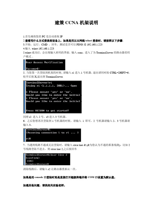
建策CCNA机架说明1.首先确保您的PC是自动获取IP2.查看用什么方式登录到设备上,如果是用以太网线telnet登录时,请按照以下步骤。
3.开始,运行,CMD ,回车,测试是否可以PING通192.168.1.2234.输入telnet 192.168.1.2235.telnet成功后,会出现输入密码的界面,输入ccna,进入了为TerminalServer的路由器的用户模式。
5.当您第一次登陆到机架的时候,请输入r1进入1号机器,退出请同时按CTRL+SHIFT+6,松开后按X,退出到TerminalServer.同理r2 进入2号,r3进入3号机器。
6.之后您想再次登陆到1号机器的时候,请输入1 即可,2 号机器请输入2,3号机器请输入3。
7.当遇到线路不通或无法登陆时,请输入clear line & (&为您认为不通的那条线路),比如2号线路登陆不进去,则clear line 2,之后按回车清除线路后,请输入r2让路由器重新认一次。
如果是用console口登陆时则是直接打开超级终端并将COM口设置为默认值。
如遇其他问题,请找相关实验老师。
实验一认识设备端口及连接一、路由器接口1. 局域网接口(1)A UI端口AUI端口它就是用来与粗同轴电缆连接的接口,它是一种“D”型15针接口,这在令牌环网或总线型网络中是一种比较常见的端口之一。
路由器可通过粗同轴电缆收发器实现与10Base-5网络的连接。
但更多的则是借助于外接的收发转发器(AUI-to-RJ-45),实现与10Base-T以太网络的连接。
当然,也可借助于其他类型的收发转发器实现与细同轴电缆(10Base-2)或光缆(10Base-F)的连接。
AUI接口示意图如图1所示。
此主题相关图片如下:(2).RJ-45端口RJ-45端口是我们最常见的端口了,它是我们常见的双绞线以太网端口。
因为在快速以太网中也主要采用双绞线作为传输介质,所以根据端口的通信速率不同RJ-45端口又可分为10Base-T网RJ-45端口和100Base-TX网RJ-45端口两类。
- 1、下载文档前请自行甄别文档内容的完整性,平台不提供额外的编辑、内容补充、找答案等附加服务。
- 2、"仅部分预览"的文档,不可在线预览部分如存在完整性等问题,可反馈申请退款(可完整预览的文档不适用该条件!)。
- 3、如文档侵犯您的权益,请联系客服反馈,我们会尽快为您处理(人工客服工作时间:9:00-18:30)。
CCNP-ISCW实验手册CCNP-ISCW实验手册 (1)实验一:MPLS配置 (2)实验二:ipsec site-to-siteVPN配置 (8)实验三:GRE VPN的配置 (16)实验四:Ezvpn的配置 (20)实验五:本地AAA的配置 (28)实验六:CBAC配置 (31)实验一:MPLS配置实验环境:三台路由器Ethernet接口相连,接口配置如图要求:在三台路由器相连的接口分别启用MPLS,查看相应的结果,在启用前使其在OSPF 下互通。
步骤一:接口配置连通性,启用OSPF路由协议R1(config-if)#int e0/1R1(config-if)#ip add 10.1.1.1 255.255.255.0R1(config-if)#no shutdownR1(config)#int e0/0R1(config-if)#ip add 20.1.1.1 255.255.255.0R1(config-if)#no shR1(config)#router ospf 100 启用路由协议,发布接口R1(config-router)#net 10.1.1.0 0.0.0.255 area 0R1(config-router)#net 20.1.1.0 0.0.0.255 area 0R2(config)#int e0/1R2(config-if)#ip add 20.1.1.2 255.255.255.0R2(config-if)#no shR2(config-if)#int e0/0R2(config-if)#ip add 30.1.1.1 255.255.255.0R2(config-if)#no shR2(config)#router ospf 100R2(config-router)#net 20.1.1.0 0.0.0.255 area 0R2(config-router)#net 30.1.1.0 0.0.0.255 area 0R3(config)#int e0/1R3(config-if)#ip add 30.1.1.2 255.255.255.0R3(config-if)#no shR3(config-if)#int e0/0R3(config-if)#ip add 40.1.1.1 255.255.255.0R3(config-if)#no shR3(config-if)#exitR3(config)#router ospf 100R3(config-router)#net 30.1.1.0 0.0.0.255 area 0R3(config-router)#net 30.1.1.0 0.0.0.255 area 0步骤二:查看路由,并测试连通性R1#show ip route →查看路由表20.0.0.0/24 is subnetted, 1 subnetsC 20.1.1.0 is directly connected, Ethernet0/040.0.0.0/24 is subnetted, 1 subnetsO 40.1.1.0 [110/30] via 20.1.1.2, 00:00:15, Ethernet0/010.0.0.0/24 is subnetted, 1 subnetsC 10.1.1.0 is directly connected, Ethernet0/130.0.0.0/24 is subnetted, 1 subnetsO 30.1.1.0 [110/20] via 20.1.1.2, 00:00:15, Ethernet0/0 R2#show ip route20.0.0.0/24 is subnetted, 1 subnetsC 20.1.1.0 is directly connected, Ethernet0/140.0.0.0/24 is subnetted, 1 subnetsO 40.1.1.0 [110/20] via 30.1.1.2, 00:00:23, Ethernet0/010.0.0.0/24 is subnetted, 1 subnetsO 10.1.1.0 [110/20] via 20.1.1.1, 00:00:23, Ethernet0/130.0.0.0/24 is subnetted, 1 subnetsC 30.1.1.0 is directly connected, Ethernet0/0R3#show ip route →查看路由表,都也学到相关路由20.0.0.0/24 is subnetted, 1 subnetsO 20.1.1.0 [110/20] via 30.1.1.1, 00:00:06, Ethernet0/140.0.0.0/24 is subnetted, 1 subnetsC 40.1.1.0 is directly connected, Ethernet0/010.0.0.0/24 is subnetted, 1 subnetsO 10.1.1.0 [110/30] via 30.1.1.1, 00:00:06, Ethernet0/130.0.0.0/24 is subnetted, 1 subnetsC 30.1.1.0 is directly connected, Ethernet0/1R1#ping 40.1.1.1 →测试连通性Type escape sequence to abort.Sending 5, 100-byte ICMP Echos to 40.1.1.1, timeout is 2 seconds:!!!!!Success rate is 100 percent (5/5), round-trip min/avg/max = 4/4/4 msR3#ping 10.1.1.1Type escape sequence to abort.Sending 5, 100-byte ICMP Echos to 10.1.1.1, timeout is 2 seconds:!!!!!Success rate is 100 percent (5/5), round-trip min/avg/max = 4/4/4 ms步骤三:启用相关接口的MPLS,及快速转发功能R1(config)#ip cef →启用快速转发功能R1(config)#int e0/0R1(config-if)#mpls ip →接口启用MPLSR2(config)#ip cefR2(config)#int e0/1R2(config-if)#mpls ipR2(config-if)#int e0/0R2(config-if)#mpls ipR3(config)#ip cefR3(config)#int e0/1R3(config-if)#mpls ip步骤四:查看MPLS状态R1#show mpls forwarding-table →查看MPLS转发表Local Outgoing Prefix Bytes tag Outgoing Next Hop tag tag or VC or Tunnel Id switched interface16 16 40.1.1.0/240 Et0/0 20.1.1.2 17Pop tag 30.1.1.0/24 0 Et0/0 20.1.1.2 R2#show mpls forwarding-tableLocal Outgoing Prefix Bytes tag Outgoing Next Hop tag tag or VC or Tunnel Id switched interface16 Pop tag 40.1.1.0/24 0 Et0/0 30.1.1.217 Pop tag 10.1.1.0/240 Et0/1 20.1.1.1R3#show mpls forwarding-tableLocal Outgoing Prefix Bytes tag Outgoing Next Hop tag tag or VC or Tunnel Id switched interface16 Pop tag 20.1.1.0/24 0 Et0/1 30.1.1.117 17 10.1.1.0/240 Et0/1 30.1.1.1 R1#show ip cef summary 查看CEF转发汇总信息及标记信息IP CEF with switching (Table Version 16), flags=0x016 routes, 0 reresolve, 0 unresolved (0 old, 0 new), peak 016 leaves, 18 nodes, 20896 bytes, 21 inserts, 5 invalidations0 load sharing elements, 0 bytes, 0 referencesuniversal per-destination load sharing algorithm, id 86C8F0BF3(0) CEF resets, 0 revisions of existing leavesResolution Timer: Exponential (currently 1s, peak 1s)0 in-place/0 aborted modificationsrefcounts: 4877 leaf, 4864 nodeTable epoch: 0 (16 entries at this epoch)Adjacency Table has 2 adjacenciesR2#show ip cef summaryIP CEF with switching (Table Version 17), flags=0x017 routes, 0 reresolve, 0 unresolved (0 old, 0 new), peak 017 leaves, 18 nodes, 21032 bytes, 22 inserts, 5 invalidations0 load sharing elements, 0 bytes, 0 referencesuniversal per-destination load sharing algorithm, id FCD3DE863(0) CEF resets, 0 revisions of existing leavesResolution Timer: Exponential (currently 1s, peak 1s)0 in-place/0 aborted modificationsrefcounts: 4879 leaf, 4864 nodeTable epoch: 0 (17 entries at this epoch)Adjacency Table has 4 adjacenciesR3#show ip cef summaryIP CEF with switching (Table Version 16), flags=0x016 routes, 0 reresolve, 0 unresolved (0 old, 0 new), peak 016 leaves, 18 nodes, 20896 bytes, 21 inserts, 5 invalidations0 load sharing elements, 0 bytes, 0 referencesuniversal per-destination load sharing algorithm, id 86B9347C3(0) CEF resets, 0 revisions of existing leavesResolution Timer: Exponential (currently 1s, peak 1s) 0 in-place/0 aborted modificationsrefcounts: 4877 leaf, 4864 nodeTable epoch: 0 (16 entries at this epoch)Adjacency Table has 2 adjacencies注:也可用show ip cef detail这条命令来查看详细信息R1#ping 40.1.1.1 测试连通性!!!!!R3#ping 10.1.1.1!!!!!步骤五:显示当前配置信息R1#show runhostname R1ip cef!interface Ethernet0/0ip address 20.1.1.1 255.255.255.0half-duplextag-switching ip!interface Ethernet0/1ip address 10.1.1.1 255.255.255.0half-duplex!router ospf 100network 10.1.1.0 0.0.0.255 area 0network 20.1.1.0 0.0.0.255 area 0!endR2#show runhostname R2!ip cef!interface Ethernet0/0ip address 30.1.1.1 255.255.255.0half-duplextag-switching ip!interface Ethernet0/1ip address 20.1.1.2 255.255.255.0 half-duplextag-switching ip!router ospf 100network 20.1.1.0 0.0.0.255 area 0 network 30.1.1.0 0.0.0.255 area 0 !endR3#show runhostname R3!ip cef!interface Ethernet0/0ip address 40.1.1.1 255.255.255.0 half-duplex!interface Ethernet0/1ip address 30.1.1.2 255.255.255.0 half-duplextag-switching ip!router ospf 100network 30.1.1.0 0.0.0.255 area 0 network 40.1.1.0 0.0.0.255 area 0 !end实验二:ipsec site-to-siteVPN配置环境:两台路由器串口相连,接口配置如图要求:用两个LOOP口模拟VPN感兴趣流来建立IPSEC VPN,IKE1阶段用预共享密钥,IKE2阶段哈希算法用sha,加密算法用DES.步骤一:接口基本配置,并测试连通性R1(config)#int s0R1(config-if)#ip add 10.1.1.1 255.255.255.0R1(config-if)#clock rate 64000R1(config-if)#no shR1(config)#int loop 0R1(config-if)#ip add 1.1.1.1 255.255.255.0R2(config)#int s1R2(config-if)#ip add 10.1.1.2 255.255.255.0R2(config-if)#no shR2(config)#int loop 0R2(config-if)#ip add 1.1.2.1 255.255.255.0R1#ping 10.1.1.2 →测试连通性,再做IPSEC!!!!!Success rate is 100 percent (5/5), round-trip min/avg/max = 28/31/32 msR2#ping 10.1.1.1!!!!!Success rate is 100 percent (5/5), round-trip min/avg/max = 32/32/32 ms配置二:配置IKE1和IKE2两个阶段,并应用到接口R1(config)#crypto isakmp policy 10→IKE1阶段策略1R1(config-isakmp)#authen pre-share→将验证修改为预共享R1(config)#crypto isakmp key cisco address 10.1.1.2→定义预共享密钥R1(config)#crypto ipsec transform myset esp-sha-hmac esp-des→定义2阶段的转换集2R1(config)#access-list 100 permit ip 1.1.1.0 0.0.0.255 1.1.2.0 0.0.0.255→定义加密感兴趣流3R1(config)#crypto map mymap 10 ipsec-isakmp→定义2阶段加密图4配置密码映射% NOTE: This new crypto map will remain disabled until a peerand a valid access list have been configured.R1(config-crypto-map)#match address 100→将列表应用到加密图R1(config-crypto-map)#set peer 10.1.1.2→指定对等体R1(config-crypto-map)#set transform-set myset→将转换集映射到加密图R1(config)#int s0R1(config-if)#crypto map mymap→将加密图应用到接口5密码映射应用到接口*Mar 1 00:25:31.499: %CRYPTO-6-ISAKMP_ON_OFF: ISAKMP is ONR1(config)#ip route 1.1.2.0 255.255.255.0 10.1.1.2→指定隧道感兴趣流的路由走向R2(config)#crypto isakmp policy 10→R2与R1端策略要匹配R2(config-isakmp)#authentication pre-shareR2(config-isakmp)#exitR2(config)#crypto isakmp key cisco address 10.1.1.1→密钥一致,地址相互指R2(config)#crypto ipsec transform-set myset esp-des esp-sha-hmacR2(cfg-crypto-trans)#exit →两端必须匹配,默认即为tunnel模式R2(config)#access-list 102 permit ip 1.1.2.0 0.0.0.255 1.1.1.0 0.0.0.255→感兴趣流,两端互指R2(config)#crypto map mymap 10 ipsec-isakmp→加密图% NOTE: This new crypto map will remain disabled until a peerand a valid access list have been configured.R2(config-crypto-map)#set peer 10.1.1.1→对端的物理地址R2(config-crypto-map)#set transform-set mysetR2(config-crypto-map)#match address 102R2(config-crypto-map)#exitR2(config)#ip route 1.1.1.0 255.255.255.0 10.1.1.1→加密图感兴趣流的路由R2(config)#int s1R2(config-if)#crypto map mymap→加密映射应用到接口下*Mar 1 00:31:58.399: %CRYPTO-6-ISAKMP_ON_OFF: ISAKMP is ON步骤三:测试流是否加密,直接用接口ping出R1#ping 1.1.2.1!!!!!Success rate is 100 percent (5/5), round-trip min/avg/max = 32/33/36 msR2#ping 1.1.1.1!!!!!Success rate is 100 percent (5/5), round-trip min/avg/max = 32/33/36 ms分别在R1和R2上查看两个阶段的关联:R1#show crypto isakmp sa→没有任何关联dst src state conn-id slotR2#show crypto isakmp sadst src state conn-id slotR1#show crypto ipsec sa→没有任何加密包,关联也没有建立interface: Serial0Crypto map tag: mymap, local addr. 10.1.1.1local ident (addr/mask/prot/port): (1.1.1.0/255.255.255.0/0/0)remote ident (addr/mask/prot/port): (1.1.2.0/255.255.255.0/0/0)current_peer: 10.1.1.2PERMIT, flags={origin_is_acl,}#pkts encaps: 0, #pkts encrypt: 0, #pkts digest 0#pkts decaps: 0, #pkts decrypt: 0, #pkts verify 0#pkts compressed: 0, #pkts decompressed: 0#pkts not compressed: 0, #pkts compr. failed: 0, #pkts decompress failed: 0 #send errors 0, #recv errors 0local crypto endpt.: 10.1.1.1, remote crypto endpt.: 10.1.1.2path mtu 1500, media mtu 1500current outbound spi: 0inbound esp sas:inbound ah sas:inbound pcp sas:outbound esp sas:outbound ah sas:outbound pcp sas:R2#show crypto ipsec sainterface: Serial1Crypto map tag: mymap, local addr. 10.1.1.2local ident (addr/mask/prot/port): (1.1.2.0/255.255.255.0/0/0)remote ident (addr/mask/prot/port): (1.1.1.0/255.255.255.0/0/0)current_peer: 10.1.1.1PERMIT, flags={origin_is_acl,}#pkts encaps: 0, #pkts encrypt: 0, #pkts digest 0#pkts decaps: 0, #pkts decrypt: 0, #pkts verify 0#pkts compressed: 0, #pkts decompressed: 0#pkts not compressed: 0, #pkts compr. failed: 0, #pkts decompress failed: 0 #send errors 0, #recv errors 0local crypto endpt.: 10.1.1.2, remote crypto endpt.: 10.1.1.1path mtu 1500, media mtu 1500current outbound spi: 0inbound esp sas:inbound ah sas:inbound pcp sas:outbound esp sas:outbound ah sas:outbound pcp sas:步骤四:用扩展ping来触发感兴趣流量R1#ping ipTarget IP address: 1.1.2.1Repeat count [5]: 10 →将包调为10个,否则一个ping看不到效果Extended commands [n]: ySource address or interface: 1.1.1.1Sending 10, 100-byte ICMP Echos to 1.1.2.1, timeout is 2 seconds:....!!!!!! →已经触发了感兴趣流,并且ping通Success rate is 60 percent (6/10), round-trip min/avg/max = 84/84/84 ms步骤五:再次查看两个阶段的关联,以及加密情况R1#show crypto isa sa →IKE1阶段关联已建立为快速模式dst src state conn-id slot10.1.1.2 10.1.1.1QM_IDLE 1 0R1#show crypto ipsec saIKE2阶段关联建立,并加密了流量,隧道也已成功建立interface: Serial0Crypto map tag: mymap, local addr. 10.1.1.1local ident (addr/mask/prot/port): (1.1.1.0/255.255.255.0/0/0)remote ident (addr/mask/prot/port): (1.1.2.0/255.255.255.0/0/0)current_peer: 10.1.1.2PERMIT, flags={origin_is_acl,}#pkts encaps: 6, #pkts encrypt: 6, #pkts digest 6#pkts decaps: 6, #pkts decrypt: 6, #pkts verify 6#pkts compressed: 0, #pkts decompressed: 0#pkts not compressed: 0, #pkts compr. failed: 0, #pkts decompress failed: 0 #send errors 14, #recv errors 0local crypto endpt.: 10.1.1.1, remote crypto endpt.: 10.1.1.2path mtu 1500, media mtu 1500current outbound spi: 84AEB2E6inbound esp sas:spi: 0x1E44AB1D(507816733)transform: esp-des esp-sha-hmac ,in use settings ={Tunnel, }slot: 0, conn id: 2000, flow_id: 1, crypto map: mymapsa timing: remaining key lifetime (k/sec): (4607999/3520)IV size: 8 bytesreplay detection support: Yinbound ah sas:inbound pcp sas:outbound esp sas:spi: 0x84AEB2E6(2226041574)transform: esp-des esp-sha-hmac ,in use settings ={Tunnel, }slot: 0, conn id: 2001, flow_id: 2, crypto map: mymapsa timing: remaining key lifetime (k/sec): (4607999/3520)IV size: 8 bytesreplay detection support: Youtbound ah sas:outbound pcp sas:R2#show crypto isa sadst src state conn-id slot10.1.1.2 10.1.1.1 QM_IDLE 1 0R2#show crypto ipsec sainterface: Serial1Crypto map tag: mymap, local addr. 10.1.1.2local ident (addr/mask/prot/port): (1.1.2.0/255.255.255.0/0/0)remote ident (addr/mask/prot/port): (1.1.1.0/255.255.255.0/0/0)current_peer: 10.1.1.1PERMIT, flags={origin_is_acl,}#pkts encaps: 6, #pkts encrypt: 6, #pkts digest 6#pkts decaps: 6, #pkts decrypt: 6, #pkts verify 6#pkts compressed: 0, #pkts decompressed: 0#pkts not compressed: 0, #pkts compr. failed: 0, #pkts decompress failed: 0 #send errors 0, #recv errors 0local crypto endpt.: 10.1.1.2, remote crypto endpt.: 10.1.1.1path mtu 1500, media mtu 1500current outbound spi: 1E44AB1Dinbound esp sas: →进站流已经产生spi: 0x84AEB2E6(2226041574)transform: esp-des esp-sha-hmac ,in use settings ={Tunnel, }slot: 0, conn id: 2000, flow_id: 1, crypto map: mymapsa timing: remaining key lifetime (k/sec): (4607999/3502)IV size: 8 bytesreplay detection support: Yinbound ah sas:inbound pcp sas:outbound esp sas: →出站流已经产生spi: 0x1E44AB1D(507816733)transform: esp-des esp-sha-hmac ,in use settings ={Tunnel, }slot: 0, conn id: 2001, flow_id: 2, crypto map: mymapsa timing: remaining key lifetime (k/sec): (4607999/3502)IV size: 8 bytesreplay detection support: Youtbound ah sas:outbound pcp sas:配置五:查看当前的配置R1#show runhostname R1!crypto isakmp policy 10authentication pre-sharecrypto isakmp key cisco address 10.1.1.2!crypto ipsec transform-set myset esp-des esp-sha-hmac!crypto map mymap 10 ipsec-isakmpset peer 10.1.1.2set transform-set mysetmatch address 102!interface Loopback0ip address 1.1.1.1 255.255.255.0!interface Serial0ip address 10.1.1.1 255.255.255.0clockrate 64000crypto map mymap!ip route 1.1.2.0 255.255.255.0 10.1.1.2!access-list 102 permit ip 1.1.1.0 0.0.0.255 1.1.2.0 0.0.0.255 !endR2#show runhostname R2!crypto isakmp policy 10authentication pre-sharecrypto isakmp key cisco address 10.1.1.1!crypto ipsec transform-set myset esp-des esp-sha-hmac!crypto map mymap 10 ipsec-isakmpset peer 10.1.1.1set transform-set mysetmatch address 102!interface Loopback0ip address 1.1.2.1 255.255.255.0!interface Serial1ip address 10.1.1.2 255.255.255.0crypto map mymap!ip route 1.1.1.0 255.255.255.0 10.1.1.1!access-list 102 permit ip 1.1.2.0 0.0.0.255 1.1.1.0 0.0.0.255 !end实验三:GRE VPN的配置环境:三台路由器串口相连,接口配置如图要求:在R1和R3之间建立GRE隧道,地址如图步骤一:接口配置连通性,R1(config)#int s0R1(config-if)#ip add 20.1.1.1 255.255.255.0R1(config-if)#no shR1(config-if)#int lo0R1(config-if)#ip add 10.1.1.1 255.255.255.0 →虚拟私有网络R1(config)#ip route 0.0.0.0 0.0.0.0 20.1.1.2 →上互联网的缺省路由ISP(config)#int s0 →ISP路由器虚拟互联网ISP(config-if)#ip add 30.1.1.1 255.255.255.0ISP(config-if)#cl ra 64000ISP(config-if)#no shISP(config-if)#int s1ISP(config-if)#ip add 20.1.1.2 255.255.255.0ISP(config-if)#cl ra 64000ISP(config-if)#no shR3(config)#int s1R3(config-if)#ip add 30.1.1.2 255.255.255.0R3(config-if)#no shR3(config-if)#int loo 0R3(config-if)#ip add 40.1.1.1 255.255.255.0→虚拟私有网络R3(config-if)#exitR3(config)#ip route 0.0.0.0 0.0.0.0 30.1.1.1→上互联网的缺省路由步骤二:测试哪些可达,哪些不可达R3#ping 10.1.1.1 →由于ISP没有私网的路由Type escape sequence to abort.Sending 5, 100-byte ICMP Echos to 10.1.1.1, timeout is 2 seconds:U.U.USuccess rate is 0 percent (0/5)R3#ping 20.1.1.1 →合法地址是能够通讯的Type escape sequence to abort.Sending 5, 100-byte ICMP Echos to 20.1.1.1, timeout is 2 seconds:!!!!!Success rate is 100 percent (5/5), round-trip min/avg/max = 56/60/64 ms步骤三:实施GRE隧道技术R1(config)#int tunnel 0 →进入隧道接口*Mar 1 00:15:45.607: %LINEPROTO-5-UPDOWN: Line protocol on Interface Tunnel0, changed state to downR1(config-if)#ip add 100.1.1.1 255.255.255.0 →指定IP地址,两端要在一个网段R1(config-if)#tunnel source s0 →指定承载隧道的源和目的接口R1(config-if)#tunnel destination 30.1.1.2*Mar 1 00:17:49.167: %LINEPROTO-5-UPDOWN: Line protocol on Interface Tunnel0, changed state to upR1(config-if)#no shR1(config)#ip route 40.1.1.0 255.255.255.0 tunnel 0 →为私有网络指路由走tunnel 接口R3(config)#int tunnel 0*Mar 1 00:19:49.919: %LINEPROTO-5-UPDOWN: Line protocol on Interface Tunnel0, changed state to downR3(config-if)#ip add 100.1.1.2 255.255.255.0R3(config-if)#tunnel source s1 →互指源和目的R3(config-if)#tunnel destination 20.1.1.1*Mar 1 00:20:32.103: %LINEPROTO-5-UPDOWN: Line protocol on Interface Tunnel0, changed state to upR3(config-if)#no shR3(config-if)#exitR3(config)#ip route 10.1.1.0 255.255.255.0 tunnel 0 →指对端的私有网络步骤四:做PING测试R1#ping 40.1.1.1 →都已PING通,证明GRE隧道已建立Type escape sequence to abort.Sending 5, 100-byte ICMP Echos to 40.1.1.1, timeout is 2 seconds:!!!!!Success rate is 100 percent (5/5), round-trip min/avg/max = 72/72/76 msR3#ping 10.1.1.1Type escape sequence to abort.Sending 5, 100-byte ICMP Echos to 10.1.1.1, timeout is 2 seconds:!!!!!Success rate is 100 percent (5/5), round-trip min/avg/max = 72/72/76 ms步骤五:验证结果R1#show int tunnel 0Tunnel0 is up, line protocol is up →tunnel接口已经UPHardware is TunnelInternet address is 100.1.1.1/24R3#show int tunnel 0Tunnel0 is up, line protocol is upHardware is TunnelInternet address is 100.1.1.2/24R1#show int tunnel 0 accounting→tunnel接口的统计信息,包的统计Tunnel0Protocol Pkts In Chars In Pkts Out Chars OutIP 10 1000 10 1000 R3#show int tunnel 0 accountingTunnel0Protocol Pkts In Chars In Pkts Out Chars OutIP 101000 10 1000 步骤六:显示当前配置R1#show runhostname R1!interface Loopback0ip address 10.1.1.1 255.255.255.0!interface Tunnel0ip address 100.1.1.1 255.255.255.0tunnel source Serial0tunnel destination 30.1.1.2!interface Serial0ip address 20.1.1.1 255.255.255.0!ip route 0.0.0.0 0.0.0.0 20.1.1.2ip route 40.1.1.0 255.255.255.0 Tunnel0EndISP#show runhostname ISP!interface Serial0ip address 30.1.1.1 255.255.255.0 clockrate 64000!interface Serial1ip address 20.1.1.2 255.255.255.0 clockrate 64000!endR3#show runhostname R3!interface Loopback0ip address 40.1.1.1 255.255.255.0!interface Tunnel0ip address 100.1.1.2 255.255.255.0 tunnel source s1tunnel destination 20.1.1.1!interface Serial1ip address 30.1.1.2 255.255.255.0!ip route 0.0.0.0 0.0.0.0 30.1.1.2ip route 10.1.1.0 255.255.255.0 Tunnel0 !End实验四:Ezvpn的配置环境:路由器(cisco)r1在一个公司的总部为EZVPN的server,远程internet用户要访问总部的内网,远程用户用的是cisco的EZVPN软件。