asco filter regulator
Festo MS4-LFR-WR 滤波器调压器说明书

81818721Applicable documents2Safety2.1Safety instructions–Only use the product in its original condition without unauthorised modifica-tions.–Only use the product if it is in perfect technical condition.–Observe the identifications on the product.–Take into account the ambient conditions at the location of use.–Before working on the product, switch off the compressed air supply and lock it to prevent it from being switched on again.2.2Intended useThe filter regulator controls the compressed air in the downstream string at the specified outlet pressure. The filter regulator smooths pressure fluctuations and removes dirt particles and condensate from the compressed air.2.3Training of qualified personnelWork on the product may only be carried out by qualified personnel who can evaluate the work and detect dangers. The qualified personnel have knowledge and experience in pneumatics.3Additional information–Contact the regional Festo contact if you have technical problems è .–Accessories è /catalogue.4Product designFig. 1:Product design Rotary knobPneumatic port P2Filter bowl Drain screw Lock releasePressure gauge Pneumatic port P15Assembly5.1Preparing assembly For use with reduced particle emission:•Remove soil from the product.5.2Direct fastening–Space required above the product: ³ 20 mm –Space required under the product: ³ 30 mm–Space required left and right of the product: ³ 30 mm–Shut-off valves are installed in the compressed air supply line.–The maximum permissible wall thickness is 2.5 mm.1.Align the product vertically in the flow direction from 1 to2. Use the numbersand the directional arrow on the product housing for orientation.2.Pull the rotary knob upwards. If necessary, remove the padlock and push inthe release lock.3.Slide the regulator head through the hole in the mounting surface.4.Tighten the hex nut MS4-WRS è 3 Additional information. Tighteningtorque: 9 Nm ± 10%.5.Press the rotary knob to lock it.5.3Wall mounting–Space required above the product: ³ 20 mm –Space required under the product: ³ 30 mm–Space required left and right of the product: ³ 30 mm–Shut-off valves are installed in the compressed air supply line.1.Align the product vertically in the flow direction from 1 to2. Use the numbersand the directional arrow on the product housing for orientation.2.Fasten the product to the mounting surface with the mounting accessoriesè 3 Additional information.6Installation, pneumatice fittings, seals and suitable tubing from the Festo catalogueè 3 Additional information.2.Screw the fittings into the pneumatic ports.3.Note the maximum screw-in depth of the connector thread. Screwing indeeper will reduce the flow rate and can damage the housing. Maximum screw-in depth: 8.5 mm4.Insert suitable tubing into the fitting to the stop.–Position tubing axial to the pneumatic ports.–Do not bend the tubing more than the minimum bending radius.7Commissioning1.Pull the rotary knob [1] to unlock it.2.Turn the rotary knob [1] completely in the z direction.3.Pressurise the system slowly: turn the rotary knob in the + direction until thedesired pressure is reached.Maintain the permissible pressure regulation range è 10 Technical data.The input pressure p1 should be at least 0.05 MPa (0.5 bar; 7.3 psi) higher than the set output pressure p2 at all times.4.Press the rotary knob [1] to lock it.8Maintenance 8.1Draining condensateDraining condensateIf the condensate reaches a level approx. 10 mm below the filter element:1.Turn the drain screw 4 anticlockwise as seen from below.ÄThe condensate drains out.2.Turn the drain screw 4 clockwise as seen from below.Draining condensate automaticallyThe filter drains automatically.8.2Changing the filter1.Exhaust the product.2.Pull the lock release [5] on the filter bowl down.3.Turn the filter bowl [3] anticlockwise manually (as seen from below) until thestop can be felt.4.Pull filter bowl [3] from the housing.5.Unlock the latch on the support module by pressing in on the upper edge.6.Pull the support module upwards.7.Unscrew the spin disc and remove the filter support.8.Install new filter cartridge:–Grip the filter cartridge and push it onto the filter support.–Screw in the spin disc. Tightening torque: 0.4 Nm ± 10%9.Press the spin disc into the filter bowl until the lock audibly engages at theend stop.10.Mount the filter bowl [3]:–Align the lock release of filter bowl with the cutout on the housing andinsert it.–Turn the filter bowl clockwise until the lock audibly engages at the endstop.8.3Cleaning•Clean the outside of the product as required with a soft cloth.Permissible cleaning agents:–Soap solution, maximum +60 °C–Petroleum ether, free of aromatic compounds9Fault clearance10Technical data10.1Technical data, mechanical10.2Technical data, pneumatic。
ASCO电磁阀简介及型号
ASCO 电磁阀ASCO电磁阀、气控阀系列产品在全球首屈一指,经过一世纪,ASCO已成为流体控制应用系统的首选。
公司生产超过3000多种标准电磁阀和20000多个非标准型号。
产品按照最严格的生产规定,在工、商业界应用非常广泛。
主要包括:控制空气、水、轻油、惰性气体、燃油、汽油、蒸汽、真空、超低温、高频率操作、液化气、除尘、自动出售机、腐蚀性介质等。
为了控制各种液态或气态流体和满足各种应用的需要,ASCO-JOUCOM ATIC在电磁阀和机械阀方面,提代了一个广泛的选择,其中流体可以是易燃、易爆介质或腐蚀性介质。
压力可达到150巴,温度可以从-50到300。
口径主要有从1/8英寸到6英寸,操作形式有常闭型,常开型和通用型的2,3,4,5通电磁阀。
通用电磁阀* 热水和蒸汽电磁阀* 用于真空系统的磁磁阀* 用于燃烧系统的电磁阀(介质是油气和燃料油)* 各种工程用电磁阀* NAMUR电磁阀* 用于除尘系统的电磁阀* 用于低温系统的电磁阀* 燃料分配电磁阀(用于各种油料加油机)* 防水锤设计的缓慢关闭式电磁阀* 比例电磁阀* 医药和分析领域用电磁阀* 用于核电厂的电磁阀* 防爆电磁阀美国ASCO电磁阀各种规格型号齐全,二位二通电磁阀:8210系列,8262系列,8263系列,238系列,106系列107系列。
二位三通电磁阀8316系列先导式,8320系列直动式。
二位四通电磁阀:8342系列直动式,8344系列先导式,8345系列先导紧凑型。
二位五通:551系列。
本安型防爆电磁阀:2位2通,2位3通,2位4通。
低功耗电磁阀,手动复位电磁阀:8015系列,8025系列,8037系列8308系列,8310系列,8327系列,8047系列,8408系列,8410系列。
21 Air Combination Air Filter + Regulator AC10B-A

Air CombinationAir Filter + RegulatorAC10B-ANote 1) When pressure is not applied, condensate which does not start the auto drain mechanism will be left in the bowl.Releasing the residual condensate before ending operations for the day is recommended.Note 2) A 1.0 MPa (145 psi) pressure gauge will be fitted. It is not assembled and supplied loose at the time of shipment.Note 3) The bracket position varies depending on the T-spacer mounting.Note 4) Pressure can be set higher than the specification pressure in some cases, but use pressure within the specification range. Note 5) Refer to Chemical data on page 46 for chemical resistance of the bowl.Note 6) This product is for overseas use only according to the new Measurement Law. (The SI unit type is provided for use in Japan.)yofCMA/Flodyne/HydradyneŀMotionControlŀHydraulicŀPneumaticŀElectricalŀMechanicalŀ(8)426-548ŀwww.cmafh.co mAir Combination Series AC10-B-AComponent Air Filter [AF]AF10-A Regulator [AR] AR10-APort size M5 x 0.8Pressure gauge port size [AR] 1/16Fluid AirAmbient and fluid temperature23 to 140°F (–5 to 60°C) (with no freezing) Proof pressure218 psi (1.5 MPa) Maximum operating pressure145 psi (1.0 MPa)Set pressure range [AR] 7.3 to 102 psi (0.05 to 0.7 MPa) Nominal filtration rating [AF] 5 µmBowl material [AF] Polycarbonate Construction [AR] Relieving typeWeight (kg)0.16AC10B-AStandard Specifications A A F + A R + A LA W + A L A F + A RA F + A F M + A R A W + A F M A F A t t a c h m e n tA F M / A F D A RA L A WyofCMA/Flodyne/HydradyneŀMotionControlŀHydraulicŀPneumaticŀElectricalŀMechanicalŀ(8)426-548ŀwww.cmafh.co mAir CombinationAir Filter + RegulatorAC20B-B to AC60B-By o f C M A /F l o d y n e /H y d r a d y n e ŀ M o t i o n C o n t r o l ŀ H y d r a u l i c ŀ P n e u m a t i c ŀ E l e c t r i c a l ŀ M e c h a n i c a l ŀ (800) 426-5480 ŀ w w w .c m a f h .c o mAir Combination SeriesAC20B-B to AC60B-BAC40B-BAC20B-BNote 2) 23 to 122°F (–5 to 50°C) for the products with the digital pressure switchNote 1) Drain guide is NPT1/8 (applicable to the AC20B-B)and NPT1/4 (applicable to the AC25B-B to AC60B-B).The auto drain port comes with ø3/8" One-touch fitting (applicable to the AC25B-B to AC60B-B).Note 2) Drain guide is G1/8 (applicable to the AC20B-B) andG1/4 (applicable to the AC25B-B to AC60B-B).Note 3) Option G, M are not assembled and supplied looseat the time of shipment.Note 4) When pressure is not applied, condensate whichdoes not start the auto drain mechanism will be left in the bowl. Releasing the residual condensate before ending operations for the day is recommended.Note 5) If the compressor is small (0.75 kW, discharge flow isless than 3.5 scfm (100 L/min[ANR])), air leakage from the drain cock may occur during start of operations. N.C. type is recommended.Note 6) When the pressure gauge is attached, a 1.0 MPa(145psi ) pressure gauge will be fitted for standard (123 psi (0.85 MPa)) type. 58 psi (0.4 MPa) pressure gauge for 29 psi (0.2 MPa) type.Note 7) The bracket position varies depending on theT -spacer or pressure switch mounting.Note 8) Make sure that the outlet pressure is released toatmospheric pressure using a pressure gauge.Note 9) Pressure can be set higher than the specificationpressure in some cases, but use pressure within the specification range.Note 10) Refer to Chemical data on page 46 for chemicalresistance of the bowl.Note 11) A bowl guard is provided as standard equipment(polycarbonate).Note 12) A bowl guard is provided as standard equipment(nylon).Note 13) The combination of float type auto drain: C and D isnot available.Note 14) Without a valve functionNote 15) The combination of metal bowl: 2 and 8 is notavailable.Note 16) For pipe thread type: NPT .This product is for overseas use only according to the new Measurement Law. (The SI unit type is provided for use in Japan.)Cannot be used with M: Round pressure gauge (with color zone). Available by request for special.The digital pressure switch will be equipped with the unit conversion function, setting to psi initially .Note 17) For options: E1, E2, E3, E4. This product is foroverseas use only according to the newMeasurement Law. (The SI unit is provided for use in Japan.)Note 18) ć: For pipe thread type: NPT only Note 19) ̅: Select with options: E1, E2, E3, E4.A CA F +A R +A LA W +A LA F +A RA F +A F M +A RA W +A F M A F A t t a c h m e n tA F M / A F D A R A LA W y o f C M A /F l o d y n e /H y d r a d y n e ŀ M o t i o n C o n t r o l ŀ H y d r a u l i c ŀ P n e u m a t i c ŀ E l e c t r i c a l ŀ M e c h a n i c a l ŀ (800) 426-5480 ŀ w w w .c m a f h .c o mSeries AC10B0A/Series AC20B-B to AC60B-BAC10B-AAC20B-BAC25B-B to AC60B-BDimensions y o f C M A /F l o d y n e /H y d r a d y n e ŀ M o t i o n C o n t r o l ŀ H y d r a u l i c ŀ P n e u m a t i c ŀ E l e c t r i c a l ŀ M e c h a n i c a l ŀ (800) 426-5480 ŀ w w w .c m a f h .c o mAir Combination SeriesAC10B-A/Series AC20B-B to AC60B-BA CA F +A R +A LA W +A LA F +A RA F +A F M +A R A W +A F MA F A t t a c h m e n tA F M / A F D A RA L A W y o f C M A /F l o d y n e /H y d r a d y n e ŀ M o t i o n C o n t r o l ŀ H y d r a u l i c ŀ P n e u m a t i c ŀ E l e c t r i c a l ŀ M e c h a n i c a l ŀ (800) 426-5480 ŀ w w w .c m a f h .c o m。
1R602 Miniature Filter Regulator 和 Miniature Reg

! WARNINGProduct rupture can cause serious injury.Do not connect regulator to bottled gas.Do not exceed maximum primary pressure rating.Installation & Service Instructions:1R602Miniature Filter / Regulator,Miniature Regulators 1/8" & 1/4" PortsISSUED: January, 2004Supersedes: November, 2003Doc.# 1R602, ECN# 040034, Rev.# 2IntroductionFollow these instructions when installing, operating, or servicing the product.Application LimitsThese products are intended for use in general purpose compressed air systems only .Maximum Operating (Inlet) Pressure:kPa PSIG bar Miniature Filter / Regulator (with Plastic Bowl)103015010.3Miniature Filter / Regulator (with Metal Bowl)172025017.2Miniature Regulator (Metal Body)200030020.0Ambient Temperature Range: 0°C to 52°C (32°F to 125°F)SymbolsInstallation1.This unit should be installed with reasonable accessibility for service whenever possible - repair service kits are available. Keep pipe and tubing lengths to a minimum with inside clean and free of dirt and chips. Pipe joint compounds should be used sparingly and applied only to the male pipe - never into the female port. Do not use PTFE tape to seal pipe joints - pieces have a tendency to break off and lodge inside the unit, possibly causing malfunction.2.Install unit so that air flow is in the direction of arrow. Installation must be upstream of and close to devices it is to service (valve,cylinder, tool etc.). Mounting of regulators may be in any position;mounting of filter/regulators must be vertical as shown in figure.3.Gauge ports are located on both sides of the regulator body for your convenience. It is necessary to install a gauge or pipe plug into each port during installation.4.To protect regulator units against rust, pipe scale, and other foreign matter, install a filter on the upstream (high pressure) side as close to the regulator as possible.Miniature Filter / RegulatorManual Drain Filter(Relieving)Miniature & Economy Regulators(Relieving)Operation of Regulator1.Before turning on air supply , turn adjusting handle counterclockwise until compression is released from control spring. Then turn on air supply and adjust regulator to desired secondary pressure by turning adjusting handle clockwise. This permits pressure to build up slowly,preventing any unexpected operation of the valve, cylinders, tools,etc., attached to the line. Adjustment to desired secondary pressure can be made only with primary pressure applied to the regulator.2.To decrease regulator pressure setting, always reset from a pressure lower than the final setting desired. For example, lowering the secondary pressure from 550 to 410 kPa (80 to 60 PSIG) is best accomplished by dropping the secondary pressure to 350 kPa (50PSIG), then adjusting upward to 410 kPa (60 PSIG).Operation of Filter / Regulator1.Both free moisture and solids are removed automatically by the Filter / Regulator.2.Manual drain filters must be drained regularly before the separated moisture and oil reaches the bottom of the element holder. Automatic drain models (pulse drain) will collect and dump liquids automatically .They are actuated when a pressure drop occurs within the filter.3.The filter element should be removed and replaced when the pressure differential across the filter is excessive.Service!Caution: SHUT OFF AIR SUPPLY and exhaust the primary and secondary pressure before disassembling unit. (Units may be serviced without removing them from the air line.)Servicing Regulator:Note: See Figure 1, 2, & 3 to aid with this procedure.1.Unlock the adjusting knob by pulling upward (with the unit in an upright position.) Then turn adjusting knob counterclockwise until compression of the control spring has been removed.2.Remove the bonnet from body. Then remove o-ring (7), piston, lip seal (9), and control spring to service the bonnet subassembly.Unscrew seat (8) to service the poppet (17), return spring (5), and /or poppet seal (6).Note:On filter / regulator units, the poppet assembly & poppet returnspring may be accessed by removing filter element.3.Clean old grease from unit and inspect seals for sign of wear (nicks,cuts, and scratches). Repair kits are available which contain the parts which are typically replaced.4.Apply a light film of grease to all seals and sliding surfaces using the grease packet supplied with repair kit.WARNINGTo avoid unpredictable system behavior that can cause personal injury and property damage:•Disconnect electrical supply (when necessary) before installation,servicing, or conversion.•Disconnect air supply and depressurize all air lines connected to this product before installation, servicing, or conversion.•Operate within the manufacturer’s specified pressure, temperature,and other conditions listed in these instructions.•Medium must be moisture-free if ambient temperature is below freezing.•Service according to procedures listed in these instructions.•Installation, service, and conversion of these products must be performed by knowledgeable personnel who understand how pneumatic products are to be applied.•After installation, servicing, or conversion, air and electrical supplies (when necessary) should be connected and the product tested for proper function and leakage. If audible leakage is present, or the product does not operate properly, do not put into use.•Warnings and specifications on the product should not be covered by paint, etc. If masking is not possible, contact your local representative for replacement labels.WARNINGFAIL URE OR IMPROPER SEL ECTION OR IMPROPER USE OF THE PRODUCTS AND/OR SYSTEMS DESCRIBED HEREIN OR RELATED ITEMS CAN CAUSE DEATH, PERSONAL INJURY AND PROPERTY DAMAGE.This document and other information from The Company, its subsidiaries and authorized distributors provide product and/or system options for further investigation by users having technical expertise. It is important that you analyze all aspects of your application, including consequences of any failure and review the information concerning the product or systems in the current product catalog. Due to the variety of operating conditions and applications for these products or systems, the user, through its own analysis and testing, is solely responsible for making the final selection of the products and systems and assuring that all performance, safety and warning requirements of the application are met.The products described herein, including without limitation, product features,specifications, designs, availability and pricing, are subject to change by The Company and its subsidiaries at any time without notice.EXTRA COPIES OF THESE INSTRUCTIONS ARE AVAILABLE FOR INCLUSION IN EQUIPMENT / MAINTENANCE MANUALS THAT UTILIZE THESE PRODUCTS.CONTACT YOUR LOCAL REPRESENTATIVE.Pneumatic DivisionRichland, Michigan 49083269-629-5000!!Miniature Filter / Regulator & Miniature Regulators 1/8" & 1/4" Ports1R602Note:Refer to Figures to determine the correct position and orientation of the various parts during assembly.5.Install lip seal onto piston with the lips of the seal facing away fromthe support flange. Then insert control spring and piston assembly into bonnet.6.Place poppet return spring and poppet assembly into bore, followedby poppet seal and seat.7.Tighten seat to body from 0.9 to 1.1 Nm (8 to 10 in-lbs) of torque.Tighten bonnet onto body from 5.6 to 7.3 Nm (50 to 65 in-lbs) of torque.8.Make sure that the control spring is still uncompressed before turningon the air supply. Turn on air supply, then slowly adjust the knob clockwise to increase downstream pressure until the desired pressure has been reached.9.To decrease regulator pressure setting, always reset from a pressurelower than the final setting desired. For example, lowering the secondary pressure from 550 to 410 kPa (80 to 60 PSIG) is best accomplished by dropping the secondary pressure to 350 kPa (50 PSIG), then adjusting upward to 410 kPa (60 PSIG).10.When the desired secondary pressure setting has been reached,push the adjusting knob down to lock it.11.Check for leaks. If leaks occur, shut off the air supply, exhaustsystem air pressure, and make necessary adjustments to eliminate leakage.Servicing Filter Element:Note: See Figure 1 to aid with this procedure.1.Unscrew threaded bowl and element holder. Then remove filterelement, deflector, and gaskets.2.Clean all internal parts, bowl, and body before re-assembling unit.See Polycarbonate bowl cleaning section.3.Install deflector, filter element, and gaskets.4.Attach element holder. T orque 0.9 to 1.4 Nm (8 to 12 in-lbs).5.To assist with retaining bowl’s o-ring while installing bowl, lubricatethe o-ring (with a mineral based oil or grease). Then place it on the bowl.6.Screw bowl into body until it is stopped by body; then back off bowl1/8 turn.7.Apply pressure to the system and check for leaks. If leaks occur,shut off the air supply, de-pressurize the system and make necessary adjustments to eliminate leakage.If you have questions concerning how to service this unit, contact your local authorized dealer or your customer service representative.Parts Identification ListItem#Description1Bowl (Miniature Filter Regulator)2Filter Element (Miniature Filter Regulator)3Deflector (Miniature Filter Regulator)4O-ring (Miniature Filter Regulator) - bowl to body5Poppet Return Spring6Poppet Seal7O-ring - body to bonnet8Seat9Lip Seal - piston to bonnet10O-ring - piston to poppet (Miniature Regulator & Filter / Regulator relieving units)11Piston (relieving shown)12Control Spring13Knob14Hex Nut15Adjusting Screw16Bonnet17Poppet (Miniature Regulator & Filter / Regulator)18Body19Gasket (Miniature Filter Regulator) - deflector to body20Gasket (Miniature Filter Regulator) - element holder to filter element 21Element Holder (Miniature Filter Regulator)22O-ring (14E) - body to drain23Twist Drain (Miniature Filter Regulator)24Spacer, Panel Mount (* Included in PS471 & PS472)Service Kits AvailableThe following service kits contain the appropriate seals and parts necessary for ordinary field service.Miniature Miniature Description Filter / Regulator Regulator Adsorber PS452PS452 5 Micron Element Kit PS403N/A40 Micron Element Kit PS401N/A Knob R35-0545P R35-0545P Metal Bowl w/Manual Drain PS447B N/A Metal Bowl w/Automatic Drain PS451N/A Mounting Bracket Kit (plastic ring)PS417B PS417B Mounting Bracket Kit (aluminum ring)PS466PS466 Mounting Bracket Kit w/Spacer (aluminum)N/A PS472* Mounting Bracket Kit w/Spacer (plastic)N/A PS471* Panel Mount Nut - Metal P01531P01531 Piston & Poppet Kit - Unbal. Rel.PS426PS426 Piston & Poppet Kit - Unbal. Non-Rel PS428PS428 Polycarbonate Bowl w/Manual Drain PS404N/A Polycarbonate Bowl w/Automatic Drain PS408N/A Springs:1-30 PSIG Range P01175P01175 1-60 PSIG Range P01174P011742-125 PSIG Range P01173P011731-15 PSIG Range P01176P01176Un-balanced, Relieving Unit FIGURE 1: Miniature Filter /Regulator -SAFETY: Transparent BowlsCAUTION:Polycarbonate bowls, being transparent and tough, are ideal for use with Filters and Lubricators. They are suitable for use in normal industrial environments, but should not be located in areas where they could be subject to direct sunlight, an impact blow, nor temperatures outside of the rated range. As with most plastics, some chemicals can cause damage. Polycarbonate bowls should not be exposed to chlorinated hydrocarbons, ketones, esters and certain alcohols. They should not be used in air systems where compressors are lubricated with fire resistant fluids such as phosphate ester and di-ester types.Metal bowls are recommended where ambient and/or media conditions are not compatible with Polycarbonate bowls. Metal bowls resist the action of most such solvents, but should not be used where strong acids or bases are present or in salt laden atmospheres. Consult the factory for specific recommendations where these conditions exist.TO CLEAN POLYCARBONATE BOWLS USE MILD SOAP AND WATER ONLY! DO NOT use cleansing agents such as acetone, benzene, carbon tetrachloride, gasoline, toluene, etc., which are damaging to this plastic.!。
ASCO NUMATICS 1 4 电磁阀说明书
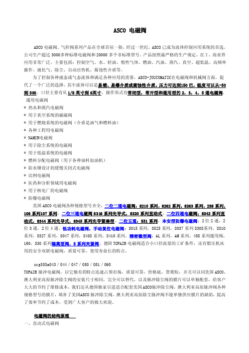
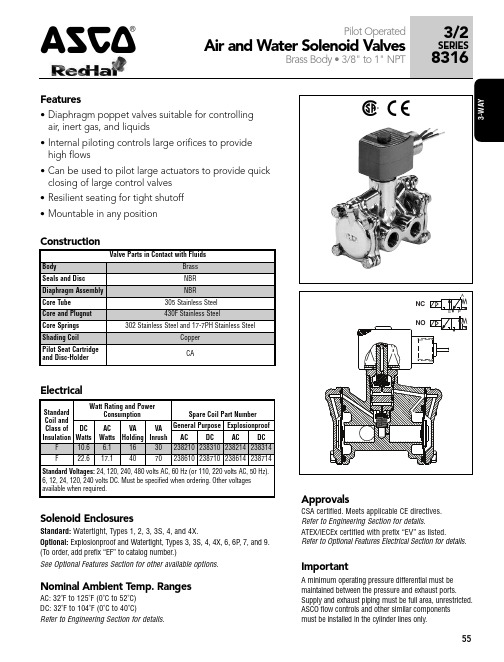
15/R 03USOLENOID VALVESno voltage release (tamperproof)manual reset construction1/4213FEATURES• The valves are certified according to IEC 61508 Functional Safety data and have SIL-3 capability (Exida approval)• Compact Tamperproof/Manual Reset function which means that the valve has to be energized as well as manually operated before it stays in the "latched" position. Because of the tamperproof feature there will be no flow from port 3 to port 2 if only the push button is pressed. The No Voltage Release (NVR) function will make sure that the valve trips when de-energized• The solenoid valves are recommended for pilot applications with basic flow, wide pressure ranges and no minimum operating pressure• PTFE rider rings and graphite-filled PTFE seals reduce friction and eliminate sticking• Coils used in metal enclosures have class H insulation materials• Peak voltage suppression diodes are standard in DC solenoids with metal enclosures• The solenoid valves satisfy all relevant EC DirectivesGENERALDifferential pressure 0 - 10 bar [1 bar = 100kPa]Maximum viscosity 65 cSt (mm 2/s)Response times75 - 100 msfluids (✶)temperature range (TS)(1)seal materials (✶)air, inert gas, water, oil-20 to +120°C -50 to + 60°CFPM (fluoroelastomer)(F)VMQ ((sillicone)(1)Can be limited by the operator ambient temperature range for explosion proof solenoidsMATERIALS IN CONTACT WITH FLUID(✶) Ensure that the compatibility of the fluids in contact with the materials is verifiedBrass bodyStainless steel body Body Brass AISI 316Stem Stainless steel Stainless steel Core tube Stainless steel Stainless steel Core and plugnut Stainless steel Stainless steel Springs Stainless steel Stainless steel Sealings and poppets FPM or (F)VMQFPM or (F)VMQ Rider Ring PTFE PTFEBPMPRPLP1,8W 3,6W - 3,7W 5,7W - 5,8W Not Available Low powerReduced powerMedium powerBasic powerPOWER LEVELS - cold electrical holding values (watt)SPECIFICATIONSpipe size orificesizeflowcoefficientKv operating pressuredifferential (bar)powerlevel prefix optional solenoidsbasic catalogue number min.max. (PS)NEMA 7&9ATEX / IECExIP65air/water (✶)Ex d Ex e mb Ex mb (mm)(m 3/h)(l/m)~/=~/=EF NF WSCR EM WSCREM PV SC brass stainless st.U - Universal, FPM sealings and poppets, manual reset1/45,70,559,2010MP -●-●--● 327B221 327B2221/45,70,559,2010RP -●-●--● 327B121327B1221/45,70,559,2010LP --●-●--- 327B322U - Universal, (F)VMQ sealings and poppets, manual reset1/45,70,559,2010MP -●-●--● 327B271 327B2721/45,70,559,2010RP -●-●--● 327B171327B1721/45,70,559,2010LP --●-●--- 327B372U - Universal, FPM sealings and poppets, manual reset tamperproof1/45,70,559,2010MP -●-●--● 327B231 327B2321/45,70,559,2010RP -●-●--● 327B131327B1321/45,70,559,2010LP --●-●--- 327B332U - Universal, (F)VMQ sealings and poppets, manual reset tamperproof1/45,70,559,2010MP -●-●--● 327B281 327B2823/2Series32715/R 03PRODUCT SELECTION GUIDESTEP 1Select basic cataloguenumber,including pipe thread indentification letter. Refer to the specifications table on page 1.Example: 8327B221STEP 2Select prefix (combination). Refer to the specifications table on page 1 and the prefix table on page 2, respect the indicated power level.Example: NFSTEP 3Select suffix (combination) if required. Refer to the suffix table on page 2, respect the indicated power level.Example: COSTEP 4Select voltage. Refer to standard voltages on page 3.Example: 230V / 50/60 Hz STEP 5Final catalogue / ordering number. Example:NF 8327B221 CO 230V / 50/60 HzPREFIX TABLEprefix description power level 1234567LP RP MP BPE M Waterproof IP66/67 - Metal enclosure (EN/IEC 60079-7,-18 and -31)*-●●-E T Threaded conduit/hole (M20 x 1,5)-●●-N F Flameproof - Aluminium (EN/IEC 60079-1, 60079-31)*-●●-S C Solenoid with spade plug connector (EN/IEC 60730)-●●-W P Waterproof IP67 - Metal enclosure -●●-W S Waterproof IP67 - 316 SS enclosure -●●-W S C R Flameproof 316L SS (EN/IEC 60079-0+1+31)*●---W S C R E M Increased Safety / Encapsulated 316L SS (EN/IEC 60079-0+7+18+31)*●---W S E M Waterproof IP66/67 - 316 SS enclosure (EN/IEC 60079-7,-18 and -31)*-●●-WS N F Flameproof - 316L SS (EN/IEC 60079-1, 60079-31)*-●●-T Threaded conduit (1/2" NPT)-●●-X Other special constructions-●●-SUFFIX TABLEsuffix descriptionpower level 12345LP RP MP BPN V FPM (fluoroelastomer) and parts cleaned for oxygen service -●●-C OEpoxy coating on all external surfaces-●●-● Available feature ❍ Available feature in DC only- Not available * A TEX/IECEx valves using these solenoids are approved according to EN 13463-1 (non electrical)(1)Functional Safety certification is not applicable with this featureOPTIONS & ACCESSORIEScatalogue number spare part kit no.(2)mounting bracket ~ / =SC 327B121C132251⏹SC 327B122C132251⏹SC 327B131C132253⏹SC 327B132C132253⏹SC 327B171C117646⏹SC 327B172C117646⏹SC 327B181C117647⏹SC 327B182C117647⏹SC 327B221C132251⏹SC 327B222C132251⏹SC 327B231C132253⏹SC 327B232C132253⏹SC 327B271C117648⏹SC 327B272C117648⏹SC 327B281C117649⏹SC 327B282C117649⏹Select 8 for NPT ANSI 1.20.3 or select G for ISO G(228/1)(2)Standard prefixes/suffixes are also applicable to kits ⏹ Mounting holes in bodyORDERING EXAMPLES VALVES:SC 8327B 12124V /DC WSEMT G 327B 122CO 24V /DC NFET G 327B 221230V /50/60 HzWSEMG 327B 12224V /DC NF 8327B 231CO 24V /DC WS G 327B 121CO 24V /DC EM8327B 221230V /50/60 Hzprefix pipe thread voltagebasic numbersuffixORDERING EXAMPLES KITS:C132251(3)NF C117646WSEM C132251prefixsuffixbasic number(3)Basic kit number applies to SC coil construction15/R 03EXPLANATION OF TEMPERATURE RANGES OF SOLENOID VALVESValve temperature rangeThe valve temperature range (TS) is determined by the selected seal material, the temperature range for proper operation of the valve and sometimes by the fluid (e.g. steam)Operator ambient temperature range The operator ambient temperature range is determined by the selected power level and the safety codeTotal temperature rangeThe temperature range of the complete solenoid valve is determined by the limitations of both temperature ranges aboveELECTRICAL CHARACTERISTICSCoil insulation class HElectrical safety IEC 335Standard voltages DC (=) 24V - 48V; Allowable voltage variation ± 10%AC (~) 24V - 48V - 115V - 230V/50/60Hz; Other voltages are available on requestprefix optionpower ratingsoperator ambienttemperature range safety codeelectrical enclosure protection (EN 60529)replacement coil / kit type (2)inrush holding hot/cold ~~=~=(VA )(VA )(W )(W ) (C°)(1)230V/50/60 Hz 24V/DC Medium Power (MP)SC5,85,85,85,2/5,7-40 to +90EN 60730IP65, moulded 400924-297400923-44201WP/WS 5,85,85,85,2/5,7-40 to +90EN 60730IP67, steel /SS 400921-297400914-44202NF/WSNF 5,85,85,85,2/5,7-60 to +60/75/90II2G Ex d IIC Gb T6/T5/T4, II2D Ex tb IIIC Db IP66/67, alu./SS 400921-297400914-44203EM/WSEM 5,85,85,85,2/5,7-40 to +40/75II2G Ex e mb IIC Gb T5/T4, II2D Ex tb IIIC Db IP66/67, steel /SS 400921-297400914-44202Reduced Power (RP)(3)SC3,73,73,73,2/3,6-40 to +60EN 60730IP65, moulded - (3)400923-04201WP/WS 3,73,73,73,2/3,6-40 to +60EN 60730IP67, steel /SS - (3)400914-24202NF/WSNF 3,73,73,73,2/3,6-60 to +60II2G Ex d IIC Gb T6, II2D Ex tb IIIC Db IP66/67, alu./SS - (3)400914-24203EM/WSEM 3,73,73,73,2/3,6-40 to +40/60II2G Ex e mb IIC Gb T6/T5, II2D Ex tb IIIC Db IP66/67, steel /SS - (3)400914-24202Low Power (LP)(3)WSCR 1,851,851,851,5/1,8-60 to +60II2G Ex d IIC Gb T6, II2D Ex t IIIC Db IP66/67, SS - (3)400961-54204WSCREM1,851,851,851,5/1,8-60 to +60II2G Ex e mb IIC Gb T6, II2D Ex tb IIIC DbIP66/67, SS- (3)400961-54204(1) Temperature range can be limited by sealings (2)Refer to the dimensional drawings on page 4(3)AC (~) limited to 127V/50/60Hz or 125V/DC - Not availableELECTRICAL CONNECTIONSprefix connectionSCSpade plug connector with cable gland EN175301-803A (ISO 4400) for cables with an outer dia-meter from 6 to 10 mmWP , WS, EM, WSEM M20 cable gland for cables with an outer diameter from 7 to 12 mm. With an internal and external facility for an earthing or bonding conductorNF , WSNF , WSCR 1/2" NPT threaded cable entry. Enclosures are supplied without cable glandWSCREM M20 x 1,5 316 SS cable gland for cables with an outer diameter from 7,2 to 11,7 mm.NFET, WSNFET M20 x 1,5 threaded cable entry. Enclosures are supplied without cable glandADDITIONAL OPTIONS●Ex mb/mD (prefix "PV") solenoid can be supplied with various cable lengths ●Compliance with "UL", "CSA" and other local approvals available on request ●Manual Reset constructions suitable for -40°C are available on requestINSTALLATION●Multi language installation/maintenance instructions are included with each valve ●The solenoid valves can be mounted in any position without affecting operation ●The mounting holes are provided in the valve body●Threaded pipe connection identifier is 8 = NPT (ANSI 1.20.3); G = G (ISO 228/1)●Declarations of conformity are available on request●Ex e mb Prefix "EM" execution: solenoid enclosure has a cable gland with integral strain relief for cables with an o.d.from 7 to 12 mm and is provided with an internal and external connection facility for an earthing or bonding conductor ●Ex d Prefix "NF/WSNF" enclosure is provided with a 1/2" NPT threaded entry hole, M20 x 1,5 (prefix "ET") is optional Both are supplied without cable gland●All DC solenoids with metal enclosure are provided with switch-off peak voltage suppression diodes15/R 03DIMENSIONS (mm), WEIGHT (kg)TYPE 01:TYPE 02:Epoxy mouldedSC: IEC 335 / ISO 4400Metal, epoxy coated / AISI 316 SS WP / WS: IEC 335EM / WSEM: EN/IEC 60079-7+18+31327B121 / B122 / B131 / B132 / B221 / B222 / B231 / B232327B121 / B122 / B131 / B132 / B221 / B222 / B231 / B232TYPE 03:TYPE 04:Aluminium, epoxy coated / AISI 316L SS NF / WSNF: EN/IEC 60079-1, 60079-31AISI 316L SS WSCR : EN/IEC 60079-0, 60079-1, 60079-31WSCREM : E N/IEC 60079-0, 60079-7, 60079-18,EN/IEC 60079-31B121 / B122 / 327B131 / B132 / B221 / B222 / B231 / B232327B322 / B332 / B372 / B382ABCØ5,512232741DGJKELMDIMENSIONS (mm), WEIGHT (kg)type prefix/option power level A B C D E F G H J K L M N weight 01SCMP/RP 5030249814995915633552786-1,30 kg 02WP , WS, EM, WSEM MP/RP 773024101158-120-81552789-1,30 kg 03NF , WSNFMP/RP 973024125176-102-545527113882,70 kg 04WSCR, WSCREMLP923024127178-116-755527115-3,10 kg15/R 03EXHAUST PROTECTOR ORDER NUMBERS¼ISO 228/1brass/nickelB-MV110014NPT B-PV110014ISO 228/1stainless steelB-VX110014NPTB-PV110014EXHAUST PROTECTOR213SECTIONAL DRAWINGExecution : Reduced Power Tamperproof-G B -- A v a i l a b i l i t y , d e s i g n a n d s p e c i fic a t i o n s a r e s u b j e c t t o c h a n g e w i t h o u t n o t i c e . A l l r i g h t s r e s e r v e d .15/R 03。
ASCO 3-WAY 55A 电磁阀说明书
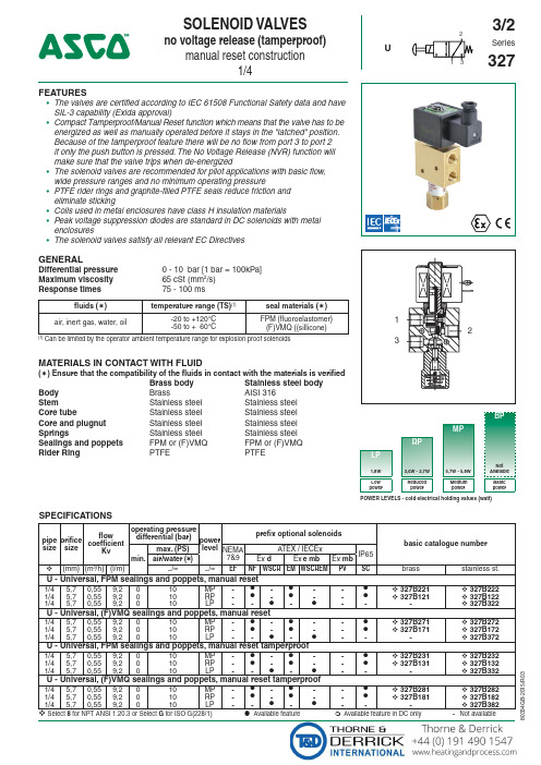
closing of large control valves • Resilient seating for tight shutoff • Mountable in any position
49
8316G024
2
17.1/F
22.6/F
3/4
17
4.1
0.7
10
9
9
9
82
49
8316G074
3
6.1/F
10.6/F
3/4
17
4.1
0.7
17
17
17
17
82
49
8316G044
4
17.1/F
22.6/F
1
25
11
0.7
10
9
9
9
82
49
8316G034
5
6.1/F
10.6/F
NORMALLY OPEN (Open when de-energized)
10
250
250
250
250
180
120
8316G016
2
17.1/F
22.6/F
1/2 5/8 3.2
10
150
125
125
125
180
120
8316G066
1
6.1/F
10.6/F
1/2 5/8 3.2
10
250
250
250
250
180
ASCO Manual Reset Valves操作手册说明书

Page 2 of 7
! " #$%&
• Direct Acting
Refers to a solenoid valve’s main orifice that is opened and closed as a direct result of the solenoid valve’s electromagnetic movement when the coil is energized and de-energized.
• Indirect Acting
Refers to a solenoid valve’s main orifice that is opened and closed as aom the electromagnetic 3-way solenoid pilot.
2 Designing a Safety Instrumented Function (SIF) using an ASCO Manual Reset Valve 4 2.1 Safety Function ............................................................................................................ 4 2.2 Environmental limits ..................................................................................................... 4 2.3 Application limits .......................................................................................................... 5 2.4 Design Verification ....................................................................................................... 5 2.5 SIL Capability ............................................................................................................... 5 2.5.1 Systematic Integrity ........................................................................................... 5 2.5.2 Random Integrity ............................................................................................... 5
ASCO电磁阀产品说明

"ia" "i"
"ib"
指火花或温度都不能点燃爆炸性环境的电路, 这些火花 或温度是标准规则指定的保养条件下产生的 (正常和非 正常运行条件下).
指元件装在一种特殊包装内的电气设备,火花或加热元
"m"
件都不能点燃爆炸性环境。
"o"
指浸在油里的电气设备.
"p"
通过中性惰性气体来增压的环境.
"q"
指粉末填充的包装.
Zone 20
Zone 22 : Accidentally present (shorttime-service- never in regular service) < 10 hours/year
电气防爆基础
温度等级
I组
温度 < 150°C or < 450°C 根据设备上积聚的煤矿粉尘
II 组
425°C 429°C - 440°C
305°C 102°C 560°C
防护类型
防护
区域
代号 0 20 1 21 2
22
"d"
描述
指爆炸性元件封装在防爆包装内的电气设备. 这种包装 抵得住爆炸性混合物爆炸时的内部压力,而且能防止爆 炸渗透周围的爆炸性环境.
标志性 图案
"e"
指安全系数高的电气设备. 这种设备免于极端的高温, 在 正常运行条件下不会产生内部和外部电弧、火花.
n-butane n-butyl alcool cyclo hexanon 1,2-dichloro-
ethan acetic acid anhydride
- 1、下载文档前请自行甄别文档内容的完整性,平台不提供额外的编辑、内容补充、找答案等附加服务。
- 2、"仅部分预览"的文档,不可在线预览部分如存在完整性等问题,可反馈申请退款(可完整预览的文档不适用该条件!)。
- 3、如文档侵犯您的权益,请联系客服反馈,我们会尽快为您处理(人工客服工作时间:9:00-18:30)。
All leaflets are available on: PIC-14-15-GB 2 0 1 0 / R 0 1FILTER/REGULATOR Full 316L Stainless Steel1/4 - 1/2Series342 IN OUTFEATURES•Stainless steel filter/regulator intended for use in potentially explosiveatmospheres caused by gases, vapours, mists and/or dust according to:(ATEX directive 94/9/EC).SAFETY CODE: ` II 2G/D c IIC X T85°C (T6) (ZONE 1-21) Explosion group IIC •Compliance with the essential health and safety requirements has been assured with European Standards EN 13463-1 and EN 13463-5•Filter/Regulator with reinforced diaphragm with PTFE lining and all metal parts in 316L stainless steel for a standard pressure of max. 20 bar•Built-in overpressure relieving function•Filtering effect by centrifugation of the air and 50 microns filtering element •Large operating temperature -40°C to +80°C•Body, bonnet and internal parts in 316L stainless steel according toASTM A 182/NACE MR 01.75•Large bowl capacityGENERALFluids Compressed air and neutral gasPorts1/4 NPT and 1/2 NPTMaximum inlet pressure20 barAdjustable pressure0,8 to 8 bar [1bar = 100 kPa]Hysteresis< 0,2 barFiltering size50 µmAmbient temperature-40° to +80°CMaximum flow (Qv at 6.3 bar)See specifications and charts CONSTRUCTIONBody AISI 316L SSBowl AISI 316L SSFiltering element AISI 316L SSDiaphragm PTFE lined NBR (Nitrile)Condensate drain Manual drainPressure adjusting screw Allen head screw with locking nutAir service equipmentSPECIFICATIONSportsize typebowlcapacityfilteringcapacityadjustablepressuremaximum flowat 6,3 bar pressure setpointand D P of 1 bar/setpointcatalogue numberFILTER / REGULATORgaugeconnectionNPTwithoutpressure gaugewith 316L SSpressure gaugeNPT(cl)(µm)(bar)l/min. (ANR)dm3/s (ANR) 50 µm filtration 0,8 - 8 bar adjustment - 316L Stainless Steel1/4 1/2314 ST312 ST13018050500,8 - 80,8 - 8800(1)1500(2)14251/41/4342080013420800334208002342080045 µm filtration 0,8 - 8 bar adjustment - 316L Stainless Steel1/4 1/2314 ST312 ST130180550,8 - 80,8 - 8680(3)1275(4)14251/41/43420800534208007342080063420800850 µm filtration 0,8 - 8 bar adjustment - 316L Stainless Steel - Automatic Drain1/4 1/2314 ST312 ST13018050500,8 - 80,8 - 8800(1)1500(2)14251/41/4342080113420801334208012342080145 µm filtration 0,8 - 8 bar adjustment - 316L Stainless Steel - Automatic Drain1/4 1/2314 ST312 ST130180550,8 - 80,8 - 8680(3)1275(4)14251/41/434208015342080173420801634208018(1) KV = 0,67 [m3/h] and 11,1 [l/min] (3) KV = 0,56 [m3/h] and 9,3 [l/min](2) KV = 1,25[m3/h] and 20,8 [l/min] (4) KV = 1,06 [m3/h] and 17,6 [l/min]All leaflets are available on: 14-15-2P I C -0014-15-G B -- A v a i l a b i l i t y , d e s i g n a n d s p e c i fi c a t i o n s a r e s u b j e c t t o c h a n g e w i t h o u t n o t i c e . A l l r i g h t s r e s e r v e d .2010/R 01SERIES 342DIMENSIONS (mm), WEIGHT(kg)INSTALLATION●Installation/maintenance instructions are included with each filter/regulator ● Filter/Regulator must be installed with the bowl in vertical position ● Air flow direction indicated by an arrow●Pipe connection has standard thread according to NPT (ANSI 1.20.3)ADDITIONAL OPTIONS●Other pipe threads are available on request ● Threaded connections BSP or with flanges ● EPDM/FPM gaskets● With a 5 µm filtering element the max. flow is reduced by approx. 15%●Stainless steel pressure gauge (0-10 bar scale division), kit number: C117814. Other scale divisions on requestcatalogue number A B C ØD E weight 34208001/002/005/006602642571/41,51,35 kg 34208003/004/007/008702702651/251,90 kg 34208011/012/015/016602642571/41,51,55 kg 34208013/014/017/018702702651/252,10 kgMOUNTING BRACKETPRESSURE DROP vs. AIR FLOW CURVEspare parts kitscatalogue number type filtration kit number 34208001/002/011/012314 ST 50 µm C11787334208003/004/013/014312 ST 50 µm C11787434208005/006/015/016314 ST 5 µm C11787534208007/008/017/018312 ST5 µmC117876OPTIONS & ACCESSORIES。