GRB-100鼓风机技术标书
离心风机技术规格书招标技术要求
离心风机技术规格书招标技术要求风机技术规格书本工程参考《建筑设计防火规范》(GB-2014)《工业建筑供暖通风与空气调节设计规范》(GB-2015)《通风与空调工程质量验收规范》(GB-2016)《工业通风机现场性能试验》(GB-2006)《一般用途离心通风机技术要求》(JB/T-2006)《滚动轴承额定动荷载的额定寿命》(GB/T6391-2010),以下要求如与规范图集冲突以规范图集为准。
1一般要求:1.1下列标准适用于本技术规格书中涉及的所有风机;1)皮带轮防护罩:在需要的位置安装满足相关标准的皮带轮防护罩,使得人员可以安全的靠近设备。
防护罩可以由一个人方便拆卸。
2)电动机:(1)电机应完好,不应有损伤、锈蚀现象,外观检查合格,每台电机应有铭牌,须注明制造厂商的名称、序号和必需的技术参数,设备操作及维修说明、零件名单、图解、部件图表、接线图表等技术文件齐全。
(2)电动机为知名品牌电机制造商,须具3C认证及有五年以上生产电动机的经验。
(3)电机的各类参数用满足设计说明请求。
(4)电机的功率至少应为风机轴功率的1.1-1.2倍。
(5)绝缘等级F级,防护等级IP54。
电机5KW以下按20%的余量考虑,5KW以上按15%的余量考虑,在合理的规模内不会过载销毁。
3)皮带驱动:(1)选择锻钢“V”形槽皮带轮。
(2)风机和电机的皮带轮以及“V”形带的功率等级应为电念头功率的1.5倍。
(3)功率大于即是0.75W的电念头应该使用相匹配的多根皮带传动。
(4)风机为可调治的皮带轮。
(5)皮带防护罩应预留转速表测定孔,测定孔尺寸满足标准转速表侧头的要求。
4)直连驱动(1)联轴器:提供法兰式联轴器,联轴器功率等级应为电动机功率的1.5倍。
5)减震(1)吊装风机箱及轴流风机由厂家提供弹簧减震器及钓钩;落地安装风机箱由厂家提供弹簧减震器;落地安装轴流风机配橡胶减震垫。
风机项箱及轴流风机配足够强度的设备吊环。
6)色标(1)轴流风机、离心风机喷上层数、名称、系统编号(喷字的规格300×110,颜色为红色)。
GRB安装操作维护手册

18
图一为GRB-80的本体结构简图,其它各机型结构类似。
名称
V型油封 轴承 齿轮
止动垫圈 止动螺帽
齿轮箱 加油栓塞 润滑油面计 泄油栓塞
材质
Viton SUJ2 20CrMnTi Q235
45 HT250
45 组合件
45
3
三维仿真图
4
9
12
序号 名称
1
机体
4
甩油片
6
骨架油封
8
主动叶轮
9
被动叶轮
10
GRB-200 620 530 30 940 194 2374 160 370 1300 650 310 580 250 190 1644 28 295 8-Ø22 6-M20x300
GRB-250 680 605 30 940 216 2579 160 392 1300 650 270 490 250 230 1748 28 350 12-Ø22 6-M20x300
5
鼓风机外形尺寸、安装基础 (配用立式出口消音器)
膨胀螺栓固定
出风口中心线
预留地脚螺栓孔(尺寸按不同机型定) 鼓风机中心线
Q E
A
B
P
N
M
K
H
n-Ød1
GSD
100
>50 D
Q E
>50 D
JG h
Ød
n-k’
>50
>50 T
>50 S
U R
P n-k
N M
>50 L
图三
单位:(mm)
型号 A B D E G H h J K M N P Q R S T U Ød n-Ød1
GRB三叶罗茨鼓风机
污水处理设备技术说明
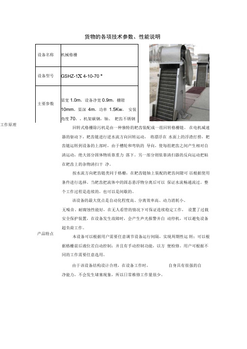
工作原理产品特点货物的各项技术参数、性能说明回转式格栅除污机是由一种独特的耙齿装配成一组回转格栅链。
在电机减速器的驱动下,耙齿链进行逆水流方向回转运动,将漂浮在水面上的浮渣打捞,耙齿链运转到设备的上部时,由于槽轮和弯轨的导向,使每组耙齿之间产生相对自清运动,绝大部分固体物质靠重力落下。
另一部分则依靠清扫器的反向运动把粘在耙齿上的杂物清扫干净。
按水流方向耙齿链类同于格栅,在耙齿链轴上装配的耙齿间隙可以根据使用条件进行选择。
当耙齿把流体中的固态悬浮物分离后可以保证水流畅通流过。
整个工作过程是连续的,也可以是间歇的。
该设备的最大优点是自动化程度高、分离效率高、动力消耗小、无噪音、耐腐蚀性能好,在无人看管的情况下可保证连续稳定工作,设置了过载安全保护装置,在设备发生故障时,会产生声光报警并自动停机,可以避免设备超负荷工作。
本设备可以根据用户需要任意调节设备运行间隔,实现周期性运转;可以根据格栅前后液位差自动控制;并且有手动控制功能,以方便检修。
用户可根据不同的工作需要任意选用。
由于该设备结构设计合理,在设备工作时,自身具有很强的自净能力,不会发生堵塞现象,所以日常维修工作量很少。
设备名称机械格栅设备型号GSHZ-1X 4-10-70 °主要参数渠宽1.0m,设备净宽0.9m,栅隙10mm,渠深4m,功率1.5Kw,安装角度70。
,机架碳钢,轴、耙齿不锈钢■J:.. iiir设备名称无密封自控自吸泵设备型号150WFZB-AD主要参数Q=150m 3/h,H=25m,N=22Kw工作原理产品特点无密封自控自吸泵主要由泵体、叶轮、泵盖、导叶、副叶轮、泵轴、连接架、电动空气控制阀等部分组成。
•该泵体内部由吸入室、储液室、气液分离室等部分组成。
泵在正常起动后,叶轮将吸入室所存的液体及吸入管路中的空气一起吸入,液体混合气体在叶轮高速旋转的离心力作用下经导叶抛入气液分离室,由于流速突然降低,气体与液体的比重不同,较轻的气体从混合液中分离出来并被排出泵外,脱气的液体重新进入工作腔与叶轮内部从吸入管路中吸入的空气再次混合,在叶轮的旋转的作用下,很快使泵体入口形成一定的真空度, 从而达到自吸的目的。
通风机变频器技术规范书(参考Word)

梁宝寺二号井通风机高压变频器技术规格书机电处:机电处长:机电科:编制人:二〇一四年四月一、总则1、本规范书仅适用于肥矿集团梁宝寺二号井主扇风机高压变频调速装置。
它提出了对该变频调速装置本体及附属设备的功能设计、结构、性能、安装和试验等方面的技术要求及供货范围。
2、本规范书提出的是最低限度的技术要求,并未对一切技术细节作出规定,也未充分引述有关标准和规范的条文,投标方应提供符合工业标准、国家标准和本规范书的优质产品。
3、如果投标方没有以书面形式对本规范书的条文提出异议,则意味着投标方提供的设备完全符合本规范书的要求。
如有异议,应在投标书中以“差异表”为标题的专门章节中加以详细描述。
4、本规范书所使用的标准如遇与投标方所执行的标准不一致时,按较高标准执行。
5、所有文件、图纸采用中文,相互间的通讯、谈判、合同及签约后的联络和服务等均应使用中文。
6、投标书及合同规定的文件,包括图纸、计算、说明、使用手册等,均应使用国际单位制(SI)。
7、本技术规范书未尽事宜,由供、需双方协商确定。
二、技术要求1、应遵循的主要标准下列标准所包含的条文,通过在本规范书中引用而构成本规范书的基本条文。
在本规范书出版时,所示版本均为有效。
所有标准都会被修订,使用本规范书的各方应探讨使用下列标准最新版本的可能性。
GB 156-2003 标准电压GB/T 1980-1996 标准频率GB/T 2423.10-1995 电工电子产品基本环境试验规程振动(正弦)试验导则GB 2681-81 电工成套装置之中的导线颜色GB 2682-81 电工成套装置之中的指示灯和按钮的颜色GB 3797-89 电控设备第二部分:装有电子器件的电控设备GB 3859.1-93 半导体电力变流器基本要求的规定GB 3859.2-93 半导体电力变流器应用导则GB 3859.3-93 半导体电力变流器变压器和电抗器GB 4208-93 外壳防护等级的分类GB 4588.1-1996 无金属化孔单、双面印制板技术条件GB 4588.2-1996 有金属化孔单、双面印制板技术条件GB 7678-87 半导体自换相变流器GB 9969.1-8 工业产品使用说明书总则GB 10233-88 电气传动控制设备基本试验方法GB 12668-90 交流电动机半导体变频调速装置总技术条件GB/T14436-93 工业产品保证文件总则GB/T15139-94 电工设备结构总技术条件GB/T13422-92 半导体电力变流器电气试验方法GB/T 14549-93 电能质量公用电网谐波IEEE std 519-1992 电力系统谐波控制推荐实施2、使用环境条件2.1周围空气温度最高温度:+45 摄氏度最热月平均温度: +30摄氏度最高年平均温度: +20摄氏度最低环境温度:-20摄氏度最大日温差:+25摄氏度地震地面水平加速度:0.3g地震地面垂直加速度:0.15g2.2海拔高度:≤1000米3、设备概况电机规格型号:YBF-800M1-10额定电压:10kv额定功率:710kw额定电流54.5A风机型号:FBCDZ-10-No36数量:4台4、基本要求4.1进线变压器4.1.1应根据变频装置的型式选择与变频装置配套的进线变压器。
鼓风机说明书资料
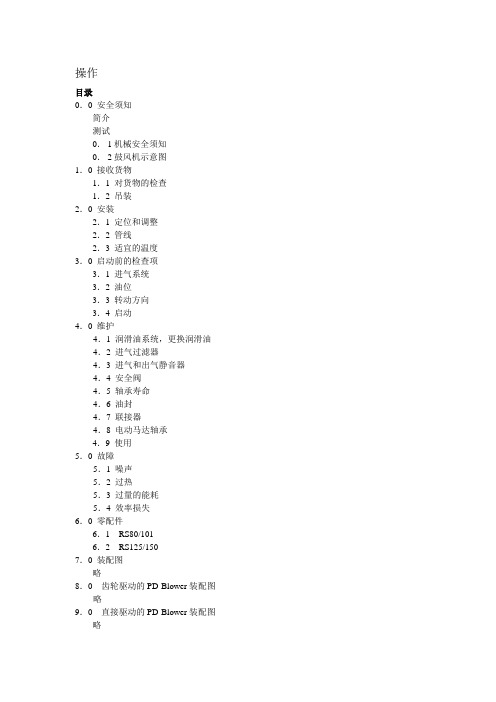
操作目录0.0 安全须知简介测试0.1机械安全须知0.2鼓风机示意图1.0 接收货物1.1 对货物的检查1.2 吊装2.0 安装2.1 定位和调整2.2 管线2.3 适宜的温度3.0 启动前的检查项3.1 进气系统3.2 油位3.3 转动方向3.4 启动4.0 维护4.1 润滑油系统,更换润滑油4.2 进气过滤器4.3 进气和出气静音器4.4 安全阀4.5 轴承寿命4.6 油封4.7 联接器4.8 电动马达轴承4.9 使用5.0 故障5.1 噪声5.2 过热5.3 过量的能耗5.4 效率损失6.0 零配件6.1 RS80/1016.2 RS125/1507.0 装配图略8.0 齿轮驱动的PD-Blower装配图略9.0 直接驱动的PD-Blower装配图略0.0 安全须知简介HV-TURBO PD鼓风机是简单而高效的卧式鼓风机,由高精度的部件组成,因而对鼓风机的任何操作必须由受过训练的专门技术人员进行,部件的精确制造确保了本机器在较小量的维护工作下,运行较长的时间。
测试在测试HV-TURBO前,先对鼓风机进行约一个小时的测试,测试内容包括性能测试和机械测试,鼓风机的防腐蚀功能可保证鼓风机在六个月的存储期间内性能不受影响,在启动时,防腐剂不必被拿走。
在有些情况下,鼓风机需要被保存一段较长的时间,在这种情况下,鼓风机应该被标明存储情况,拆开,并在使用前清洗。
0.1 机械安全须知投入使用:投入使用时,必须按照操作规程和铭牌上的要求操作仪器吊装:在1.2中标明了机器的重量,吊装过程须按照1.2中相关示意图进行。
机械要求:所有旋转部分必须被固定的物件护住(按照EN294和EN953),在仪器安全有保障的情况下,护住物才能被移开。
应避免松动的护住物,在遥控状态下,护住物和被护物之间要保持一段安全的距离,以防止出现状况。
自动启动/停止:鼓风机应该被设置为遥控状态,在这种状态下,鼓风机的开和停都是自行开始,没有预警的。
高空风GRIB报文解析及精度分析
BUFR: Binary Universal Form)、 用 于 数 据 表 示 和 字 符 格 式 ( CREX : Character Represention form for data Exchange ) 和二进制
(
C、 D、 E 代表分别代表第 12、 18、 24h 的 预 报 , 气 象 中 心 提 供 850hpa、700hpa、 500hpa、 400hpa、 300hpa、 250hpa、 200hpa 和
2. GRIB 表示意义
按国际气象组织建议把全球划 分为 8 个区域 , 如表 1 所示 , 分别 用 I、 J、 K、 L、 M、 N、 O 和 P 表 示 ; 每 个 栅 格 大 小 为 1.25 ×1.25, 每 个 区 域 共 有 3447 个 栅 格 ; 分 别 用 U、 V、 T 表 示 水 平 方 向 上 的 东 风/ 西风 , 南风 / 北 风 及 温 度 值 ; 用
三类 ) 关系做相应映射 , 并对处理后 的数据进行分析 。
WOB 数 据 的
波动性进行 分析 , 以 确 定
WOB 的 稳 定
性 , 在确 保 其 稳定的基础 上 对 GRIB 预测数据进 行分析 , 否 则 分析失去其 意义 。
图 4 WOB 方差折线图
三、预测数据分析
本文分析思想 是 WOB 数 据 为 飞机实时采集的真实数据 , 理论上
D D E
(三)GR IB解析 1. GRIB 解析过程
气象资料的分析使用很大程 度上依赖于数据的图形化和可 视 化 处 理 , GRIB 数 据 也 不 例 外 。 而 网 格 资 料 分 析 工 具
WOB 数据作为实时
绿固(Greenheck)SQ和BSQ离心式内联风机产品说明书

Centrifugal Inline FansMarch20232Greenheck’s model SQ and BSQ centrifugal inline fans feature a unique combination of installation flexibility, rugged construction, ease of service, high efficiency and low sound levels. These compact inline fans are the ideal selection for indoor clean air applications including intake, exhaust, return or make-up air systems where space is a prime consideration. The need for costly square-to-round transition pieces is eliminated reducing installation costs. The square housing design, compact size and straight-thru airflow also give the system designer the flexibility to mount SQ and BSQ fans in any configuration — horizontal, vertical or at any angle.nB roadest performance in the industry, up to 4 in. wg and 27,700 cfm.n P erformance as cataloged is assured. All fan sizesare tested in our AMCA Accredited Laboratory, and all models are licensed to bear the AMCA Sound, Air and FEI seal.n U L Listed for Electrical.nThese Greenheck products are subjected toextensive life testing to assure the fans will provide many years of reliable performance.Over the years Greenheck has listened to your needs and input to remain the industry leader.nEach fan is tested at the factory prior to shipping. The test includes a vibration check, adjusting RPM and maximum amp draw.nEach fan displays a permanently stamped metal nameplate with complete model number, mark and unique serial number for future identification.nPackaged-product is tested in accordance with ISTA (International Safe Transit Association) standards and procedures.Turn to our inline fans to meet your requirements for applications in office buildings, schools and hospitals.Model ComparisonModelLocationMountingAirflowApplicationDriveTypeImpeller TypePerformanceR e l a t i v e C o s tO u t d o o rI n d o o rR o o f C u r bB a s e /F l o o r H a n g i n gW a l lC e i l i n g M o u n t e dE x h a u s tS u p p l yR e v e r s i b l eR e c i r c u l a t eG e n e r a l /C l e a n A i rC o n t a m i n a t e d A i rS p a r k R e s i s t a n tG r e a s e (U L 762)S m o k e C o n t r o l (U L )H i g h W i n d (150 m p h )H i g h T e m p (a b o v e 200°F )B e l tD i r e c tC e n t r i f u g a lP r o p e l l e r /A x i a lM i x e d F l o wM a x i m u m V o l u m e (c f m )M a x i m u m S t a t i c P r e s s u r e (i n . w g )SQ ✓✓✓✓✓✓✓✓✓✓5,000 2.5$BSQ✓✓✓✓✓✓✓✓✓27,7004$Greenheck Fan Corporation certifies the model SQ and BSQ fans shown herein are licensed to bear the AMCA Seal. The ratings shown are based on tests and procedures performed in accordance with AMCA Publication 211 andPublication 311 and comply with the requirements of the AMCA Certified Ratings Program.UL/cUL 705Listed for Electrical File no. E40001UL electrical is optional and must be specifiedCentrifugal Square Inline Fans3Housing ConstructionThe fan housing is constructed of rigid structural members and formed galvanized steel panels. (Aluminum construction is optional in SQ sizes 60-160 and in BSQ sizes 70-300).Drive FrameConstructed from heavy-gauge steel.WheelBackward inclined, non-overloading centrifugal wheel is utilized to deliver maximum efficiency. Each wheel is statically and dynamically balanced.Duct CollarsInlet and discharge duct collars are provided for easy duct connection. The square design provides a larger discharge area than tubular centrifugal and vane axial fans; outlet velocities are reduced for quieter operation.MotorPermanently lubricated, sealed ball bearing motors are selected to provide years of trouble-free operation with minimal maintenance.Bearings100 percent factory-tested bearings are designed specifically for air handling applications with a minimum L10 life in excess of 100,000 hours (L50 average life in excess of 500,000 hours).Drive AssemblyDrives are sized for a minimum of 150 percent of driven horsepower. Machined cast iron pulleys are factory set to the required RPM and adjustable for final system balancing. Belts are static free and oil resistant. Belt adjustment is accomplished by loosening fasteners, sliding the motor plate and retightening fasteners.Fan ShaftFan shafts are precisely sized, ground and polished so the first critical speed is at least 25 percent over the maximum operating speed. Close tolerances where the shaft makes contact with bearings result in longer bearing life.Disconnect SwitchA NEMA-1 disconnect switch is provided as standard. All wiring and electrical components comply with the National Electric Codes and materials are UL Listed. Other NEMA enclosure disconnect switches are optional.Access PanelsThe cabinet construction features two removable access panels permitting easy access to all interiorcomponents.Construction FeaturesShown with access panels, motor coversand bearing covers removedSQ DIRECT DRIVEBSQ BEL T DRIVEOptions and AccessoriesAluminum ConstructionAluminum construction is available for all direct drive sizes 60-160 and belt drive sizes 70-300. Some drive frame components may still be of steel construction to maintain structural integrity.Inlet and Outlet GuardsInlet and outlet guards provide protection for non-ducted applications. Guards are fabricated of welded wire on a galvanized steel frame. They are easily removed for maintenance and inspection.Belt Drive Motor Cover and Belt GuardFor belt-driven fans, combination motor coverand belt guards constructed of galvanized steelare available for protection of motors, drives and personnel. Standard on units specified with UL. Direct Drive Motor CoverFormed, galvanized steel motor covers are available to isolate direct drive motors from the airstream. When motor covers are furnished, vents to the exterior of the fan are provided to ensure sufficient motor cooling.Speed ControllersAvailable for use with shadedpole and permanent splitcapacitor (PSC) motors onmodel SQ fans. They providean economical means ofsystem balancing with directdrive fans.Insulated HousingFor noise reduction and condensation control, the interior of the fan housing can be lined with a 1-inch fiberglass duct liner. The optional motor cover can also be insulated.The table depicts the radiated sound reductionthat can be obtained in each octave band for the insulated housing and motor cover together.Approximate Radiated Sound Attenuation (dB)Octave Band12345678 Sizes 60 - 130-2-7-4-4-6-13-13-9 Sizes 140 - 420-3-2-5-4-5-5-7-8Backdraft DampersGravity or motorized parallel blade dampers (model WD-330) are available for duct mounting. These dampers feature sturdy galvanized frames, aluminum blades with vinyl bladeseals, and a balanceddesign for minimalresistance to airflow.Control DampersSquare, opposed blade volumecontrol dampers (model VCD) areavailable for duct mounting. Thesedampers feature sturdy galvanizedframes, and steel blades withoptional blade and jamb seals. Abalanced design results in minimalresistance to airflow.45Motor StartersThe fundamental function of a motor starter is to protect the motor from damage that can occur from overheating. With a Greenheck motor starter, you will be provided with the best motor protection available. Specific model components may include; physical interface, overload protection, disconnect, magnetic contactor, NEMA-1 orNEMA-3R steel enclosures and pre-engineered easy system integration. For complete information on specific Greenheck Motor Starter models refer to , Products, Motor Starter page.Wiring PigtailAllows direct hook-up to the power supply eliminating field wiring at the fan.CoatingsA wide variety of coatings and colors are available. Greenheck coatings and resistance charts can be found in the Performance Coatings Commercial and Industrial Fans color chart and in our Coatings Application Guide.Permatector™ is our standard coating. Typically used for applications thatrequire corrosion resistance in indoor and outdoor environments. Color is RAL 7023 concrete grey.Hi-Pro Polyester is resistant to salt water, chemical fumes and moisture in more corrosive atmospheres. It has superior chemical resistance, excellent abrasion and outdoor UV protection. This coating has protective qualities that exceed Air Dry Heresite. Color RAL 7023 concrete grey is standard; choose from sevenstandard decorative colors or color match any color.Industrial Epoxy is a high performance epoxy with excellent chemical resistance in interior applications to a wide variety of chemicals including acids, caustics, solvents, and high moisture.Options and AccessoriesPERMATECTORModel Fan SizeFilter Box Weight^Filter Size(s)Filter QuantitySQDirect Drive 80, 90, 957414 x 25197, 98, 998014 x 2511008816 x 20212011416 x 252130 (HP)12020 x 202140 (HP)17420 x 252160 (HP)24620 x 204BSQ Belt Drive70, 80, 9016816 x 20210016916 x 202130 (HP)19720 x 202140 (HP)23120 x 252160 (HP)28520 x 204180 (HP)29320 x 254200 (HP)36112 x 25316 x 253240 (HP)49620 x 25416 x 254300 (HP)75920 x 258360 (HP)95716 x 251020 x 255420118516 x 25520 x 2510galvanized construction and largest cataloged open drip proof motor.Note: 24-inch side clearance is recommended for accessing and removing filters.INDUSTRIAL EPOXYHI-PRO POLYESTERFilter OptionsThe filter box is designed to provide a compact and convenient clean air solution. Factory-assembled as a single unit, this fan eliminates the costly process of designing, fabricating and installing specialremote filter box assemblies. Both the fan and filter section feature removable access panels on both sides to remove and replace filters, making fan maintenance simple and fast.6DimensionsABDC1 in. (25mm)Model Fan SizeABCD*E*F*GDamper SizeMax Fan Weight^SQDirect Drive60, 701213128-7/8---9 x 92680, 90, 9515161511-7/8---12 x 124197, 98, 9915211511-7/8---12 x 124910017211713-7/8---14 x 145612019211915-7/8---16 x 1667130 (HP)21212117-7/8---18 x 1867140 (HP)23222319-7/8---20 x 20104160 (HP)26262622-7/8---23 x 23160BSQ Belt Drive70, 80, 9017-1/82117-1/811-7/817-3/41313-1/412 x 1210610017-1/82117-1/813-7/817-3/41313-1/414 x 1410712019-1/82119-1/815-7/8201713-1/416 x 16124130 (HP)21-1/82121-1/817-7/8201713-1/418 x 18131140 (HP)23-1/82223-1/819-7/8201713-1/420 x 20146160 (HP)26-1/82626-1/822-7/8201713-1/423 x 23188180 (HP)27-1/82827-1/823-7/8201713-1/424 x 24195200 (HP)31-1/83231-1/827-7/830201628 x 28246240 (HP)38-1/83438-1/834-7/830201635 x 35350300 (HP)46384641-7/834221842 x 42537360 (HP)52425247-7/834221848 x 48686All dimensions in inches and weight is shown in pounds. *Motor cover is optional. Size may be greater depending on motor. ^Weight shown is standard galvanized construction and largest cataloged open drip proof motor.ABC*ED*G*F1-1/2 in.(38mm)SQ DIRECT DRIVEBSQ BEL T DRIVEPerformance00.511.522.5330,00025,00020,00015,00010,00050000BSQ Belt Drive 00.511.522.53SQ Direct Drive S t a t i c P r e s s u r e (i n . w g)Volume (CFM)100999897958090607012013014016000.511.522.5330,00025,00020,00015,00010,0005000BSQ Belt Drive00.511.522.53600050004000300020001000SQ Direct DriveS t a t i c P r e s s u r e (i n . w g )Volume (CFM)S t a t i c P r e s s u r e (i n . w g )Volume (CFM)10070120130********9016020030024036042000.511.522.5330,00025,00020,00015,00010,00050000BSQ Belt Drive 00.511.522.536000500040003000200010000SQ Direct Drive 00.511.522.5330,00025,00020,00015,00010,0005000BSQ Belt Drive600050004000300020001000000.511.522.533.544.5BSQ-HP Belt Drive18,00016,00014,00012,000800040002000600010,000Volume (CFM)S t a t i c P r e s s u r e (i n . w g )Volume (CFM)S t a t i c P r e s s u r e (i n . w g )Volume (CFM)0SQ DIRECT DRIVEBSQ BEL T DRIVE8Number Code and InstallationBSQ - 120 HP - VGTYPICAL INSTALLATIONModels SQ and BSQ ducted inline fans are designed for the exhaust, supply or recirculation of air in a building. Typical installation requires ductwork on the inlet and outlet side of the fan. A minimum of three duct diameters is required on the inlet and outlet of the fan to minimize system effect losses. See the diagram below for a typical installation.Installations can include flexible duct connections (by others) on either the inlet or outlet side of the fan or both. The motor is rigidly mounted and can be oriented in any direction (top, bottom, side).The model BSQ ducted inline fan must be installed with the motor accessible for maintenance and inspection.External isolators are recommended, hanging (shown below) or base mounted.Installation must meet all local governing codes and the NEC.Flexible duct (by others)3 Duct Diameters3 Duct Diameters PRESSURE LEVEL (Belt Drive Only)HP - High Pressure WheelMODEL CONFIGURATION BSQ - Belt Drive SQ - Direct DriveFAN SIZE60 through 420VG = Vari-Green ® Motor (Direct Drive only)MODEL NUMBER CODEThe model number system is designed tocompletely identify the fan. The correct code letters must be specified to designate belt or direct drive. The remainder of the model number is determined by the size and performance.9The side discharge option helps to reduce system effect. It will increase performance and reduce installation labor. The most notable is reducing system effects. Note: The Figure 1 example shows the air being discharged into the corner. It will take several duct lengths before the airflow becomes laminar or smooth again after making the turn. In Figure 2, the fan is placed in the corner using a side discharge. In this configuration the airflow pattern at discharge is smooth and supports a more predictable system. Remember the duct length on the discharge side should be approximately two to three wheel diameters to achieve catalog performance.Discharge ConfigurationFan performance will change with different discharge positions. Catalog data is based on an inlinedischarge. Right side discharge will give you 108% of cataloged performance and left side will give you 109% of cataloged performance. Use Figure 3 to locate the orientation to fit your application. Figures 4 and 5 illustrate the proper side discharge definitions. Refer to Greenheck’s CAPS ® (Computer Aided Product Selection) program or consult factory for performance modifications.FanFanFigure 1Figure 2Left Side DischargeRight Side DischargeAccess DoorInletHeightWidthHeightLeft Side DischargeInletWidthAccess DoorModel Fan SizeWidthHeightSQDirect Drive 80, 90, 9512-7/811-7/897, 98, 9913-7/811-7/810013-7/813-7/812015-7/815-7/8130 (HP)17-7/817-7/8140 (HP)19-7/819-7/8160 (HP)22-7/822-7/8BSQ Belt Drive70, 80, 90, 10012-1/213-7/812012-1/215-7/8140 (HP)13-1/219-7/8160 (HP)17-1/222-7/8180 (HP)19-1/223-7/8200 (HP)23-1/227-7/8240 (HP)25-1/243-7/8300 (HP)31-7/841-7/8360 (HP)32-7/837-7/842034-7/843-7/8All dimensions in inches.Side Discharge Duct OpeningsFigure 4Figure 5Left DischargeRight Discharge Left and Right DischargeFigure 3Discharge OptionsMounting OptionsAAAAFFEE B B B BG G Hanging rails by othersFigure 7:Horizontal Hanging or Base MountGGBBBBDDDDHanging rails by othersFigure 8:Vertical Hanging or Base MountAAAACCCCFFEEBBB GG Hanging rails by othersFigure 6:Horizontal Hanging or Base MountModel Fan SizeABCDEFGSQDirect Drive Hanging rails not included.Supplied byothers.80, 90, 9513-1/419-3/415-1/89-3/84327-3/897, 98, 9918-5/819-3/415-1/89-3/848-3/827-3/810018-5/821-3/419-5/813-7/843-3/422-3/412018-5/823-3/421-5/815-7/849-1/828-1/8130 (HP)18-5/825-3/423-5/817-7/84423140 (HP)19-5/827-3/425-5/819-7/85028160 (HP)23-1/23128-3/422-7/849-1/223-5/8BSQ Belt Drive70, 80, 90, 1001821-13/1619-7/814-1/850-7/829-7/8Hanging rails notincluded. Supplied byothers.1201823-13/1621-7/816-1/855-3/434-3/4130 (HP)1825-13/1623-7/818-1/850-1/429-1/4140 (HP)1927-13/1625-7/820-1/85634160 (HP)2331-3/162923-1/855-3/429-3/4180 (HP)2532-3/163024-1/857-3/429-3/4200 (HP)2936-3/163428-1/866-3/834-3/8240 (HP)3143-3/164135-1/868-1/234-1/2300 (HP)355146-3/440-7/869-1/831-3/8360 (HP)39-3/85752-5/846-3/476-5/834-3/4All dimensions in inches.All fan models can be mounted horizontally, vertically or at an angle. For ease of installation, knockouts are provided at each location where mounting brackets are shown in Figures 6, 7 and 8. Optional brackets are universally adjustable to mount in any of these locations.With either a hanging or base mount the motor may be located on either side. The base mount allows top access panels only.With a hanging mount, the motor may be located on either top or bottom. The base mount allows top motor location only. Both options provide access panels on two sides.Mounting brackets are turned 90° for vertical mounting. Access panels are located on the two sides adjacent to the motor.11Base Mount or Hanging IsolatorsComplete isolation kits areavailable with either neoprene or spring isolators and are sized to match the weight of the specified fan size. The base isolator support brackets are designed to permit mounting of the fan with the motor located on top or either side. The hanging isolator support brackets are designed to permit mounting of the fan with the motor located on top, bottom or side. Note: Hanging rods to be supplied by others.ModelFan SizeHIJJ1KLSQ Direct Drive 60, 70, 80, 90, 95, 97, 98, 99, 100,120, 130 (HP), 1-3/85-1/21-3/82-3/86-3/42-5/16160 (HP)1-3/85-1/21-3/82-1/26-3/42-5/8BSQ Belt Drive120, 130 (HP), 1-3/85-1/21-3/82-3/86-3/42-5/8160 (HP), 180 (HP), 200 (HP), 240 (HP),300 (HP), 360 (HP), 4201-3/85-1/21-3/82-1/26-3/42-5/8All dimensions in inches.Standing SpringSTANDING SPRING ISOLATORK H K H J1Mounting Style A Mounting Style B Mounting Style AMounting Style BH J H IHJ 5/8 inch(16mm)nominal5/8 inch(16mm)nominalI H J1Mounting Style AMounting Style BL H J Mounting Style AH J1Mounting Style BStanding NeopreneKHKHJ1Mounting Style A Mounting Style B Mounting Style A Mounting Style B HJ HI HJ1Mounting Style A Mounting Style BL HJMounting Style ALHJ1Mounting Style BHanging NeopreneK H K H J1Mounting Style A Mounting Style B HJH J1IHJ1Mounting Style A Mounting Style BL HJ Mounting Style A H J1Mounting Style B Hanging SpringKHJKHJ1Mounting Style AMounting Style BHIH J1Mounting Style AMounting Style BL HJMounting Style A HJ1Mounting Style BP.O. Box 410 • Schofield, WI 54476-0410 • Phone (715) 359-6171 • As a result of our commitment to continuous improvement, Greenheck reserves the right to change specifications without notice.Specific Greenheck product warranties are located on within the product area tabs and in the Library under Warranties.00.F&V.1016 R10 3-2023Copyright © 2023 Greenheck Fan Corp.Model SQ (direct drive) is available with Greenheck’s Vari-Green ® technology. Vari-Green products are design for efficiency, controllability and low maintenance.ControlsFor expanded controllability, Greenheck offers many different solutions to fit any need. Controls are designed specifically for Vari-Green motors. These controls are available for applications requiring manual operation or demand-controlled ventilation (DCV). Applications utilizing DCV controls provide only the desired amount of ventilation, delivering building owners savings on their energy bills.Manual Controls• Dial on Fan • Remote Dial • T ouch RemoteMotorsThe Greenheck Vari-Green motor is an electronically commutated (EC)motor that operates on single or three phase AC power input and internally converts it to DC power providing better speed control capabilities (up to an 80% turndown) and higher efficiencies than standard motors.The Vari-Green motor blends technology, controllability and energy efficiency in a low maintenance package that has changed the way the industry designs, specifies and operates air movement equipment. Depending on power rating, Vari-Green motors are available in both single and three phase with either a dial-mounted potentiometer (speed control) or wired to accepta 0-10 VDC control signal from an external source.Vari-Green ® OptionsDemand Controlled Ventilation• Hand/Off/Auto (HOA)• Constant Airflow • Constant Pressure• Air Quality - Volatile Organic Compound (VOC)• Air Quality - T emperature/Humidity• 0-10 VDC Signal from Building ManagementSystem (BMS)。
磁悬浮离心式鼓风机技术规范书
磁悬浮离心式鼓风机技术规范书一、鼓风机主要组成磁悬浮离心式鼓风机机组包括但不限于:叶轮及蜗壳、高速变频电机、变频器、悬浮轴承及其控制器、UPS电源、电机冷却辅助系统、冷却系统、风道(如有)、空气过滤系统、出口柔性接头、进风口消声器(如有)、出风口消声器、止回阀、电(气)动放空阀(安全阀)、就地控制柜、隔音罩等,以及其它有效保证安全运行所需的附件。
鼓风机配套进风管道、出风管道、冷却管道、放空管道,及安装所需的地脚螺栓、紧固件等。
二、成套机组系统要求1、鼓风机设备鼓风机设备按照工艺需求的参数进行型号匹配,明确选型方案,对采购产品性能参数进行响应。
(1)安全联锁系统必须对突然断电、工艺系统波动、大颗粒物进入、喘振、悬浮轴承跌落等突发情况有安全应对方案措施。
(2)环境适应性:鼓风机能适应污水处理现场工况,防气体腐蚀、防潮。
(3)鼓风机在正常工作范围内应运行无振动,无异响,无漏气现象。
在供应商提供的性能曲线上任意一点运行,电机都不会过载。
(4)每台鼓风机可根据信号要求自动控制其流量变化,起动和停车时放空阀应自动打开以保证无负荷起动和停车及防止发生喘振。
(5)多台鼓风机必须能够并联运行,在并联运行条件下,每台鼓风机应能满足不同流量的调节需要。
2、鼓风机组(1)每台鼓风机应配置独立的现场控制柜(含变频器),现场控制柜应室内安装,采购人为现场控制柜提供AC380V,50Hz的电源。
(2)现场控制柜内应具有短路及过载保护,并设热保护元件用于电机短路、过载保护;控制柜柜面上应配备人机界面,所有的参数设定、显示、控制等均应通过显示屏完成。
操作界面要求使用简体中文。
(3)现场控制柜应带有显示屏。
鼓风机运行情况应能够实时进行监测,显示数据应包括(不限于此):风量、压力比、进口压力、出口压力、电机电流、电机电压、电机温度、变频器温度、进口压力、进口空气温度、运行时间。
(4)在鼓风机的运行过程中,如果控制系统检测到故障,风机会自动报警或停机,且控制柜上会显示故障信号。
- 1、下载文档前请自行甄别文档内容的完整性,平台不提供额外的编辑、内容补充、找答案等附加服务。
- 2、"仅部分预览"的文档,不可在线预览部分如存在完整性等问题,可反馈申请退款(可完整预览的文档不适用该条件!)。
- 3、如文档侵犯您的权益,请联系客服反馈,我们会尽快为您处理(人工客服工作时间:9:00-18:30)。
鼓风机GRB-100
使用地点:调节池鼓风机
型式:三叶罗茨鼓风机
型号:GRB-100
数量:2台
风量:8.00m3/min
风压:6Kpa
噪音:小于80dBA
出口口径:100 mm
重量:311Kg(不含电机)
配套电机功率:15KW
◇技术特点:
川源公司GRB型三叶罗茨风机为严格品质管理,标准化制品。
采用电脑动平衡校正,特殊叶轮设计,使用一级研磨齿轮,两转子与机壳之间间隙很小,使转子能自由运动而无过多泄露,两转子旋转方向相反,可使气体机壳一侧吸入,另一侧排出。
风量与转速成正比,在转速一定时,出口压力提高,风量仍可保持不变。
叶轮采用四轴加工的方法,一次加工完成,精度高;叶轮采用复合曲线、效率高运转平稳;GRB两叶轮的间隙小(0.08mm-0.4mm),提高效率轴承及齿轮采用齿轮油循环润滑,磨损及发热量小,保养容易;GRB轴承及其他零部件均采用标准化,更换及维修方便、快捷;GRB重要部件,如齿轮
由专业生产厂加工制造,保证工件的准确性及高精度;
◇供货范围
1,每套鼓风机供应完整成套,保证鼓风机组能够正常运行。
主要包括:主机、配套电动机、传动装置、进出口消音器、进出口过滤器、底座、挠性接头、压力表、止回阀、安全阀、三角皮带、滑轨。
2,用于罗茨鼓风机的维护保养的必备手册。
◇鼓风机系统
除整机在醒目处设置铭牌外,鼓风机、电机等非单一工厂生产的配套件,均设有铭牌,旋转件有旋向箭头,气流有流向箭头;
进出气接口法兰符合中国国家标准规定;
鼓风机可适应24小时连续运行和间歇频繁启动,运行时保持稳定,无异常振动。
在鼓风机额定转速时,轴承座上径向振幅(双向)不大于0.14mm;
鼓风机机组运行平稳,无异常噪音,无震动,无过热现象,保证在距风机隔音罩外侧1m处噪音不大于80dBA。
在额定工况流量下,压力差允许误差±5%。
风机转子组装前的静平衡和动平衡实验的精度达到6.3级。
1)风机机壳、机座、墙板、油箱由铸铁FC25制造,采用树脂砂铸造,时效处理。
鼓风机机壳具有160℃的设计温度,和表压110Kpa 的设计压力。
接口进行机加工光滑平整,保证装配气密封。
2)每台鼓风机上都有吊耳,可独自承受鼓风机的重量。
3)风机叶轮材质为FCD500,轴材质为SCM440,经调质处理,
精密加工和研磨达到应有尺寸。
轴的使用寿命可达到200,000小时。
轴具有足够的尺寸,以承受各种运行条件下连接运行所产生的全部荷载。
在叶轮轴穿过机壳的位置,有一道迷宫式密封,以减少空气泄露。
穿过齿轮箱处,有多道迷宫式密封以防止齿轮箱中油的泄露。
4)传动齿轮材质20CrMnTi,经高频淬火处理,采用磨齿加工制造1 级精度。
使用寿命能达100,000小时。
齿轮传动装置的外壳体,由铸铁制造,具有足够刚度,在最大荷载时仍能保持轴的位置不动。
齿轮壳体的部件经精密加工,以使其与轴承安装。
轴承采用飞溅油润滑,材料为SUJ2,轴承的设计于电机在100%的负载下操作时,能达到五年(50,000小时)运转寿命。
(符合标书中要求)
5)每一设备都有高强度的铸铁底座,可安装在混凝土基础上。
基础与底座有支撑填塞垫、尖钉,并与结合体或相关设备排列配合,并有足够的空间作为灌浆或电线管之用。
所有钢板间的接口连续焊接及磨平每台鼓风机的配套底座底板作为一个单独部件由型钢制造而成,带有吊耳,具有足够的刚度,使得在起吊底板及上面安装设备时不会产生变形或对基座底板和机器部件造成损坏。
(符合标书中要求)
7)鼓风机与电机采用皮带传动。
◇鼓风机附属设备及材质
1)进口消音器:主要消除鼓风机进口气流噪声,装置重量轻,阻力小,消音效果好,由A3钢制造。
2)出口消音器:主要消除鼓风机出口气流噪声,消声频带宽,消音效果好,由A3钢制造。
3)压力安全阀:当系统工作状况异常,阻力高于额定值35mbar时,安全阀开启,将气体从安全阀排出,防止风机和电机过载。
5)压气止回阀:是用以防止停机时系统高压气体倒流,使风机转子反转,而发生故障。
6)出口橡胶柔型接头:是由橡胶钢板骨架压合而成,具有良好的减震和隔音效果。
6)压力表:每台风机提供一个排气压力表,现场指示排气压力。
7)螺栓、螺母:锚固螺栓及特别注明的螺栓、螺帽均采用不锈钢材质。
(符合标书中要求)
◇电动机
鼠笼式感应电动机:电源380V±10%,50Hz±10%
功率:5.5KW
防护等级:IP54
绝缘等级:F级
每台鼓风机配有卧式、恒速、鼠笼式感应电动机。
电机功率大于整个设计工况范围内的最大负荷值的110%。
当电机在满载而不超载连续运转的情况下,该电机的温升必须不超过NEMA 标准 MG-1或等同标准低一级绝缘材质所规定的限度。
电机根据ISO02373标准制造,振动值为25M。
在一个平衡电压供给系统中,当电机在其使用因素内的任何负载运转
时,多相电机各极的不平衡电流不超过5%。
所有电机都有外壳、轴承托架、风扇盖。
电机铭牌包括以下内容:型号、绝缘等级、功率、满负荷电流、转速、温升、制造厂名称和系列编号、电压、接线图。
电机的转子须经过动平衡校正,最大振幅在低于1,800rpm时,不超过0.04mm;在同步转速为3,000rpm时,不超过0.03mm。
(均符合标书要求)
◇安装地脚和鼓风机试验
鼓风机安装在本公司提供的地脚上,以吸收鼓风机的质量和振动,同时防止产生不适当的应力和变形。
每台鼓风机出厂前都会进行试验,以确定其整个性能范围内的机械和空气动力学性能满足要求。
出厂试验报告包括记录数据,确定工况点保证值。
◇油漆及表面处理
所有表面按本公司标准复涂两层油漆,加以保护。
油漆后的表面不会遭受撞击、摩擦、褪色以及其它因素的损伤。
(符合标书中要求)
◇工具和备件
无需特殊工具;
各部分零件均按标准规格制造,并能随时在现场更换、安装。
相同的零件可互相更替。
(符合标书中要求)
◇接口
设备及管道之间的法兰连接,其规格必须符合ISO标准。
(符合标书中要求)
◇包装
所有机械设备采用简装木箱,有完整的保护措施,可免于暴露,保持干燥。
(符合标书中要求)
电机的包装适合常规运输和不少于6个月的无采暖室内储存。
◇说明
所有金属材料都有较好的强度、延伸性及耐用性。
铸铁为坚韧的、结构致密,无气孔、缺陷和龟裂;承受应力的锻件为细质的、均匀的;铸铁、钢材及其它材质符合各设备规范中的要求。
所有选用的材料均是全新的、未使用过的。
所有设备的传送带或链条、叶片、联轴、暴露的中心轴以及其他转动部分都有较好安全防护的护盖。
每一防护设备都能容易安装与拆卸,并附有所需的支撑及附件;。