简易电阻、电容和电感测试仪设计说明
电阻电容电感测试仪
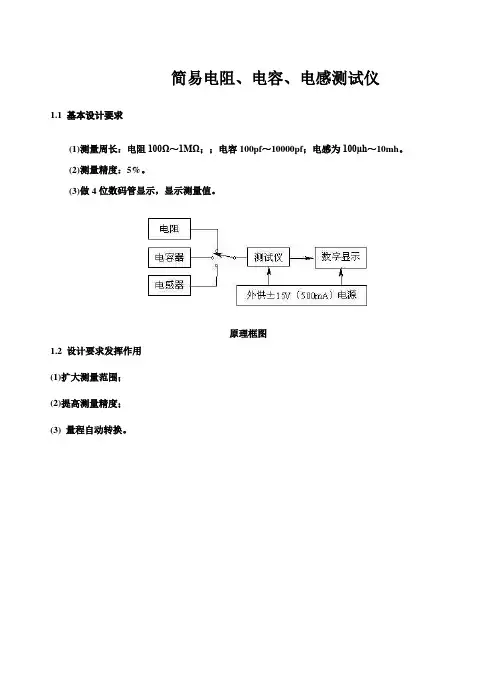
简易电阻、电容、电感测试仪1.1 基本设计要求(1)测量周长:电阻100Ω~1MΩ;;电容100pf~10000pf;电感为100μh~10mh。
(2)测量精度:5%。
(3)做4位数码管显示,显示测量值。
原理框图1.2 设计要求发挥作用(1)扩大测量范围;(2)提高测量精度;(3) 量程自动转换。
本系统采用555多谐振荡器电路将电阻、电容参数转换为频率,电感通过电容的三点振荡转换为频率,使模拟量近似转换为数字量,频率f 为数字量单片机可轻松处理,测量精度高,易于实现自动化。
而且,由单片机组成的应用系统具有很高的可靠性。
系统扩展和灵活的系统配置。
什么样的应用系统容易构建,应用系统的软硬件利用率高。
单片机可编程,硬件的功能描述完全可以用软件实现,设计时间短,成本低,可靠性高。
综上所述,将振荡电路与单片机结合实现电阻、电容、电感测试仪更加简单可行,节约了成本。
因此,本设计基于单片机。
关键词: 单片机, 555多谐振荡器电路, 电容三点振荡一、 系统演示1. 电阻测试方案演示 方案一:电阻分压法。
图 1.1结构如图 1.1 所示。
待测电阻Rx 和参考电阻R 串联在电路中。
由于电阻分压的影响,当串联在电路中的电阻Rx 的阻值不同时,Rx 两端的压降也不同。
Rx 可以通过测量 Vx 获得。
)(X X X V VCC R V R -=这个方案的原理很简单。
理论上,只要参考电阻准确,您就可以测量任何电阻。
但在实际应用中,由于AD 的分辨率有限,当待测电阻非常大或非常小时,很难测量Rx 上的压降Vx ,从而缩小了测量范围。
为了提高测量范围和精度,需要分阶段测试电阻,提高AD 的分辨率。
这无疑会增加系统的复杂性和成本。
选项 2:桥接法。
图 1.2结构如图 1.2 所示。
Rx=R2*R3/R1电桥法又称零位指示法。
它采用归零电路作为测量指标,工作频率较宽,能在很大程度上消除或减弱系统误差的影响,精度高。
但是为了保证电桥的平衡,信号源的电压和频率要稳定,特别是波形失真要小,增加了硬件电路的难度。
电阻、电容、电感测量仪的设计
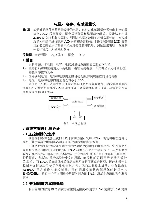
电阻、电容、电感测量仪摘要:基于对元器件参数测量设计的电阻、电容、电感测量仪系统由主控制器部分、A/D采样部分、语音播报部分和显示部分组成。
设计以单片机AT89S52为主控核心器件,利用继电器对凌阳单片机实现控制,使其对放置元件端口进行高速A/D采样和语音播报,同时终端控制LCD液晶显示器实时显示当前的电抗元件参数值和性质。
测试结果表明:系统整体运行稳定,人机界面友好。
关键词:参数测量A/D采样语音LCD1引言分析赛题,本电阻、电容、电感测量仪系统需要实现如下功能:1)能够自动辨识出被测元件是电阻、电容还是电感,并实时显示元件的阻值、容值和感值的大小。
2)能够实现电阻、电容和电感测量的自动切换,并实现量程的自动切换。
3)电阻、电容和电感的测量误差均小于0.5%。
基于以上分析,采用模块设计的方案实现系统的各项功能,系统主要由主控制器部分、数据测量部分、A/D采样部分、语音播报和显示部分,具体的实现方案如系统主框图1所示:图1 系统主框图2系统方案设计与论证2.1主控制器的选择在主控制器的选择上我们有以下两种方案:采用FPGA(现场可编程逻辑门阵列)作为系统的控制核心和基于单片机技术的控制方案。
上述两种控制方式除在处理方式和处理能力(速度)上的差异外,实现效果及复杂程度等方面也有显著的区别。
FPGA将器件功能在一块芯片上,其外围电路较少,集成度高。
而单片机技术成熟,开发过程中可以利用的资源和工具丰富、价格便宜、成本低。
鉴于本设计中实时显示,单片机的资源已经能满足设计的需求,而FPGA的高速处理的优势在这里却得不到充分体现,因此本设计的控制方案模块选用基于单片机控制方案。
我们选择技术成熟,性价比高的AT89S52单片机作为主控制器,同时采用凌阳其内部系统时钟频率为11.0592MHz,执行一个单周期指令所需时间为仅83nS,满足本系统的软件编写需求。
2.2 数据测量方案的选择目前常用的智能RLC测试方法主要是阻抗-相角法和V-I复数法。
简易数字式电阻、电容和电感测量仪设计
简易数字式电阻、电容和电感测量仪设计报告摘要:本系统利用TI公司的16位超低功耗单片机MSP430F149和ICL8038精密函数发生器实现对电阻、电容和电感参数的测量。
本系统以自制电源作为LRC数字电桥和各个主要控制芯片的输入电源,并采用ICL8038芯片产生高精度的正弦波信号流经待测的电阻、电容或者电感和标准电阻的串联电路,通过测量电阻、电容或者电感和标准电阻各自的电压,利用电压比例计算的方法推算出电阻值、电容值或者电感值。
利用MSP430F149单片机控制测量和计算结果,运用自校准电路提高测量精度,同时用差压法,消除了电源波动对结果的影响。
测量结果采用12864液晶模块实时显示。
实验测试结果表明,本系统性能稳定,测量精度高。
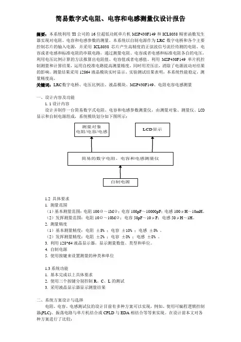
关键词:LRC 数字电桥、电压比例法、液晶模块、MSP430F149、电阻电容电感测量一、设计内容及功能1.1设计内容设计并制作一台简易数字式电阻、电容和电感参数测量仪,由测量对象、测量仪、LCD 显示和自制电源组成,系统模块划分如下图所示:1.2 具体要求1. 测量范围(1)基本测量范围:电阻100Ω~1MΩ;电容100pF~10000pF;电感100μH~10mH。
(2)发挥测量范围:电阻10Ω~10MΩ;电容50pF~10μF;电感50μH~1H。
2. 测量精度(1)基本测量精度:电阻±5% ;电容±10% ;电感±5% 。
(2)发挥测量精度:电阻±2% ;电容±8% ;电感±8% 。
3. 利用128*64液晶显示器,显示测量数值、类型和单位。
4. 自制电源5. 使用按键来设置测量的种类和单位1.3系统功能1. 基本完成以上具体要求2. 使用三个按键分别控制R、C、L的测试3. 采用液晶显示器显示测量结果二、系统方案设计与选择电阻、电容、电感测试仪的设计目前有多种方案可以实现,例如、使用可编程逻辑控制器(PLC)、振荡电路与单片机结合或CPLD与EDA相结合等等来实现。
课程设计电阻电感电容测试仪
课程设计(论文)说明书题目:简易电阻电容电感测量仪院(系):信息与通信学院专业:信息对抗技术学生姓名:学号:指导教师:职称:年月日摘要随着电子工业的发展,电子元器件急剧增加,电子元器件的适应范围也逐渐广泛起来,在应用中我们常常需要测量电阻的大小。
因此,设计可靠,安全,便捷的电阻测量仪具有极大的现实必要性。
而单片机是目前设计应用中用得比较广泛的器件,它可以通过软件编程来达到不同的效果,实现各种各样的不同功能,具有灵活性强,可靠性高,可扩展性好等优点。
在系统硬件设计中,以MCS-51单片机为核心的电阻测量仪,将电阻使用振荡电路转化频率实现参数的测量。
电阻是采用555多谐振荡电路产生,将振荡频率送人STC89C52的计数端口,通过定时并且计数可以计算出被测频率,在通过该频率计算出被测参数。
关键词:单片机;555多谐振荡电路Abstract:With the development of electronic industry,electronic components rapidly increased the scope of electronic components widely up gradually,in applications we often measured resistors,capacitors,inductors size. Therefore,the design of reliable,safe,convenient resistance,capacitance,inductance tester of great practical necessity.And the microcontroller is the device that uses extensively in the designs application currently,it can attain the different result by the software compile,carryingout different kinds of functions,have advantages of good dexterity,high credibility,can expand good and so on.In the system hardware design,take the MCS-51 monolithic integrated circuit as the core resistance,the electric capacity,the inductance reflectoscope reflector,the resistance,the electric capacity,the inductance,the use correspondence's oscillating circuit transforms for the frequency realizes each parameter survey.And the resistance and the electric capacity are use 555 multiresonant circuits to produce,the oscilation frequency will send STC89C52 the counting to be neat,through and fixed time counts may calculate by the frequency measurement rate,figures out again through this frequency meter is measured the parameter.Key words:Microcontroller; 555 resonance swings circuit目录引言 (4)1 设计功能及要求 (6)2 电阻测试仪的系统设计 (6)2.1电阻测试仪设计方案比较 (6)2.2系统的原理框图 (7)3 系统硬件电路设计 (7)3.1 STC单片机及显示电路的设计 (7)3.2 555多谐振荡电路的设计 (8)3.2.1 555定时器简介 (8)3.2.2电阻测量电路的设计 (11)4 软件设计 (12)4.1主程序流程图 (12)4.2 中断服务程序流程图 (13)5 系统测试及整机指标 (13)6 结论 (13)谢辞 (14)参考文献 (15)附录 (16)引言1.设计的背景及意义随着电子工业的发展,电子元器件急剧增加,电子元器件的适应范围也逐渐广泛起来,在应用中我们常常需要测量电阻的大小。
简易电阻、电容、电感测量仪
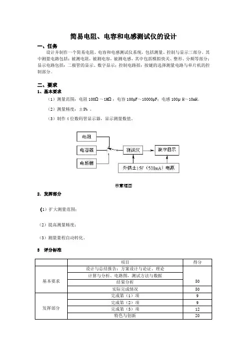
简易电阻、电容和电感测试仪的设计一、任务设计并制作一个简易电阻、电容和电感测试仪系统,包括测量、控制与显示三部分。
其中测量电路包括:被测电阻,被测电容,被测电感,其中包括模拟快关、整形、分频等部分;显示电路包括:二极管的显示、数字显示;控制电路括:按键的选择测量电路与单片机的控制部分。
二、要求1、基本要求(1)测量范围:电阻100Ω~1MΩ;电容100pF~10000pF;电感100μH~10mH。
(2)测量精度:±5% 。
(3)制作4位数码管显示器,显示测量数值。
示意框图2.发挥部分(1)扩大测量范围;(2)提高测量精度;(3)测量量程自动转化。
3 评分标准项目得分基本要求设计与总结报告:方案设计与论证、理论50 计算与分析、电路图,测试方法与数据结果分析实际完成情况50发挥部分完成第(1)项9 完成第(2)项9 完成第(3)项12 特色与创新20摘要:本文先对设计功能及要求进行了阐述,然后提出要完成该功能的设计方案,最后综合考虑之后选定方法,再对电阻,电容,电感的测量电路进行设计。
本设计是利用单片机来实现测试的,其中电阻和电容是采用555多谐振荡电路产生的,而电感则是根据电容三点式产生的,从而实现各个参数的测量。
在电阻的测量电路中,我们把它分为两档来进行测量,并用单片机来驱动继电器以实现,这样,一方面测量精度较高,另一方面便于使仪表实现智能、自动化。
关键词:单片机 555多谐振荡电容三点式继电器In this article, the function and the requirement of design were introduced, and then puts forward to want to complete the function, the design of the last comprehensive consideration selection methods, and then a resistor, capacitor, inductor measurement circuit design. This design is to realize the test using single chip computer, of which the resistor and capacitor is used more than 555 resonance swing circuitry, and inductance is produced according to the capacitance SanDianShi, so as to realize the measurement of each parameter. In the resistance and capacitance measurement circuit, we put it into two files to make the measurement, and single chip microcomputer to drive the relay to realize, so that, on the one hand, has high accuracy, on the other hand to make intelligent instrument and automation.Key words: more than 555 single chip microcomputer chip oscillation capacitance SanDianShi relay一、系统方案论证1.1 电阻测试模块电路方案一:电阻分压法。
电阻电容电感测试仪的设计论文说明
电阻电容电感测试仪的设计摘要随着电子技术的迅速发展,电子器件用品已经成为人们不可缺少的工具之一。
最近一直提倡,节约能源,绿色环保。
既然节约能源,本设计是一种基于单片机(89C51)的高精度电阻电感电容测量仪器的设计.本设计采用MAX038单片压控函数发生器产生高精度的正弦波信号流经待测的电容或者电感和标准电阻的串连电路,利用电压比例计算的方法推算出电容值或者电感值,利用51单片机控制测量和计算结果,采用1602液晶模块实时显示数值,可以手动调节量程,正弦信号发生器可以实现幅值和频率的调整,为了提高精度,我们把被测的交流电压先通过ICL7650来消除因为AD637输入电阻较低产生的误差.实验测试结果表明,本设计性能稳定,测量精度高.关键词:电压比例法 89C51 AD637 1602液晶AbstractThe design is the design of a highprecision instrument for RLC measurement based on microcontroller(89C51).This design adopted M AX038monolithic voltagecontrolled function generator to produce hig h accuracy sine wave signal,which passed through the series circ uit of the capacity or inductance and standard resistance,and th en measured the respective voltage of the capacity or the induc tance and the standard ing the voltage proportion me thod calculated the capacitance values or inductance values.The design used 51 microcontroller to control the measurement and cal culation results,used 1602 LCD to show the result. The range ca n be adjusted manually, sine signal generator can adjust amplitu de and frequency to improve accuracy, we measured the AC voltag e through the ICL7650 to eliminate the error caused by the low er input resistance of AD637. Experimental results show that the performance of this design is stable and of high measurement accuracy.Keywords: Voltage proportion method; 89C51; AD637; 1602 LCD;目录摘要.................................................... 错误!未定义书签。
简单电阻,电容和电感检验测试仪设计
课程设计任务书学生姓名:专业班级:指导教师:工作单位:信息工程学院题目: 简易电阻、电容和电感测试仪设计初始条件:LM317 LM337NE555 NE5532STC89C52 TLC549 ICL7660 1602液晶要求完成的主要任务:1、测量范围:电阻100Ω-1MΩ;电容100pF-10000pF;电感100μH-10mH。
2、测量精度:5%。
3、制作1602液晶显示器,显示测量数值,并用发光二级管分别指示所测元件的类别。
时间安排:指导教师签名:年月日系主任(或责任教师)签名:__________ 年月日目录摘要 (4)ABSTRACT (5)1、绪论 (7)2、电路方案的比较与论证 (7)2.1电阻测量方案 (7)2.2电容测量方案 (9)2.3电感测量方案 (11)3、核心元器件介绍 (12)3.1LM317的介绍 (12)3.2LM337的介绍 (13)3.3NE555的介绍 (14)3.4NE5532的介绍 (17)3.5STC89C52的介绍 (18)3.6TLC549的介绍 (20)3.7ICL7660的介绍 (23)3.81602液晶的介绍 (24)4、单元电路设计 (26)4.1直流稳压电源电路的设计 (27)4.2电源显示电路的设计 (28)4.3电阻测量电路的设计 (29)4.4电容测量电路的设计 (30)4.5电感测量电路的设计 (31)4.6电阻、电容、电感显示电路的设计 (32)5、程序设计 (33)5.1中断程序流程图 (33)5.2主程序流程图 (34)6、仿真结果 (34)6.1电阻测量电路仿真 (34)6.2电容测量电路仿真 (35)6.3电感测量电路仿真 (36)7、调试过程 (37)7.1电阻、电容和电感测量电路调试 (37)7.2液晶显示电路调试 (38)8、实验数据记录 (38)心得体会 (40)参考文献 (41)附件 (42)附件1:电路图 (42)附件2:元件清单 (43)附件3:程序代码 (45)附件4:实物图 (64)摘要近几年来,电子行业的发展速度相当快,电子行业的公司企业数目也不断增多。
电阻、电容和电感测量仪的设计
XXX 学院电子设计竞赛作品研究与设计报告作品名称:电阻、电容和电感测量仪的设计作者:指导老师:摘要:本系统是基于AT89S52单片机测量电阻、电容和电感的对应振荡电路所产生的频率,从而实现各个参数的测量。
其中电阻和电容是采用555多谐振荡电路产生的,而电感则是根据电容三点式产生的。
AT89S52的定时器可以利用外部时钟源来计数,这里我们将 RCL的测量电路产生的频率作为单片机AT89S52的时钟源,通过计数则可以计算出被测频率在通过该频率计算出各个参数。
此系统一方面实现了测量精度高,测量误差小,另一方面便于使仪表实现自动化,系统能自动识别电阻、电容和电感,并自动进行量程切换及在128*64液晶屏上显示其数值大小。
关键词:AT89S52555芯片74LS197分频电路CD4052多路开关目录1引言 (3)2方案设计 (4)2.1设计思路 (4)2.2方案比较与选择 (4)2.3硬件模块设计 (5) (5) (6) (7) (8) (9) (9) (10)2.4系统软件设计 (10)3数据测试及误差分析 (11)4结论 (13)参考文献 (14)附录 (15)1引言目前,市场上如万用表等测量电阻、电容和电感的元器件数不胜数,但是随着技术的进步,人们对元器件功能、精度和效率等的要求越来越高,为此,我们通过AT89S52单片机设计了测量电阻、电容和电感对应振荡电路所产生的频率实现各个参数的测量。
本系统分为四个部分,第一部分,通过555电路构成的多谐振电路将被测电阻转化为频率信号;第二部分,与第一部分相似也是采用555电路将电容转化为相应的频率信号输出;第三部分,采用电容的三点式振荡电路将电感转化为与之对应的频率信号输出;最后一部分,也就是显示部分,具体的讲就是用MSP430单片机运用一定的软件系统将输入的频率信号转化为相应的被测量的一个过程。
这四大版块共同构成了建议电阻电容和电感测试仪的整个电路系统。
简易电阻、电容和电感测试仪设计
元器件参数测量仪的设计1 .加深对电路分析、摹拟电路、数字逻辑电路、微处理器等相关课程理论知识的理解;2.掌握电子系统设计的根本方法和普通规则;3.熟练掌握电路仿真方法;4.掌握电子系统的制作和调试方法;1.设计并制作一个元器件参数测量仪。
2.〔根本要求〕电阻阻值测量, *围: 100 欧~1M 欧;3.〔根本要求〕电容容值测量, *围: 100pF~10 000pF;4.〔根本要求〕测量精度:正负 5% ;5.〔根本要求〕 4 位显示对应数值,并有发光二极管分别指示所测器件类型;6.〔提高要求〕增加电感参数的测量;7.〔提高要求〕增加三极管直流放大倍数的测量;8.〔提高要求〕扩大量程;9.〔提高要求〕提高测量精度;10.〔提高要求〕测量量程自动切换;电阻电容电感参数测量常用电桥法,该方法测量精度,但是电路复杂。
也可为简化起见,电阻测量也可采用简单的恒流法,电容采用 555 定时电路;在现代化生产、学习、实验之中,往往需要对*个元器件的具体参数发展测量,在这之中万用表以其简单易用,功耗低等优点被大多数人所选择使用。
然而万用表有一定的局限性,比方:不能够测量电感,而且容量稍大的电容也显得无能为力。
所以制作一个简单易用的电抗元器件测量仪是很有必要的。
现在国内外有不少仪器设备公司都致力于低功耗手持式电抗元器件测量仪的研究与制作,而且精度越来越高,低功耗越来越低,体积小越来越小向来是他们不断努力的方向。
该类仪器的根本工作原理是将电阻器阻值的变化量,电容器容值的变化量,电感器电感量的变化量通过一定的调理电路统统转换为电压的变化量或者频率的变化量等等,再通过高精度 AD 采集或者频率检测计算等方法来得到确定的数字量的值,进而确定相应元器件的具体参数。
2.1 电阻测量方案方案一:利用串联分压原理的方案根据串联电路的分压原理可知,串联电路上电压与电阻成正比关系。
测量待测电阻R*和电阻 R 上的电压,记为 U 和 U0 * 0.方案二:利用直流电桥平衡原理的方案R 2根据电路平衡原理, 不断调节电位器 R 3,使得电表指针指向正中间, 再测量电位器电阻值。
简易电阻、电容和电感测试仪设计原理
简易电阻、电容和电感测试仪设计原理简易电阻、电容和电感测试仪一、任务设计并制作一台数字显示的电阻、电容和电感参数测试仪,示意框图如下:二、要求1.基本要求.基本要求(1)测量范围:电阻100Ω~1M Ω;电容100pF 100pF~~10000pF 10000pF;电感;电感100μH ~10mH 10mH。
(2)测量精度:±5% 。
)测量精度:±5% 。
(3)制作4位数码管显示器,显示测量数值,并用发光二极管分别指示所测元件的类型和单位。
三、设计步骤三、设计步骤1、分模块测量电路的设计原理(1)电阻测量电路的基本原理电阻测量仪的关键技术是电阻测量仪的关键技术是R X /V 转换器,转换器,R R X 即所需测量的电阻,无论电路多么复杂,总可以把与R X 相并联的元件等效为两只互相串联的电阻R 1和R 2。
由此构成三角形电阻网络,其原理图如下所示:上图中R 0为量程电阻,只要使R 1两端呈等电位,此时U R1=0=0,则,则R 1相当于开路,路,R R 2变成运放的负载电阻,变成运放的负载电阻,R R 1和R 2就不起分流作用,这样即可直接测就不起分流作用,这样即可直接测 R R X 的阻值。
的阻值。
E E 为测试电压,为测试电压,I I S 为测试电流,设流过R X 和R 1的电流分别为I X 和I 1,根据基尔霍夫定律可知:,根据基尔霍夫定律可知:I S =I X + I 1又根据“虚地”原理,则又根据“虚地”原理,则U R1= I 1 R 1=0故I 1=0=0,可忽略不计。
由此得到:,可忽略不计。
由此得到:,可忽略不计。
由此得到:I S =I X再考虑到C 点接地,则D 点为“虚地”,因此:点为“虚地”,因此:I S=E/ R0进而推导出:进而推导出: U X= I X R X= I S R X= (E/ R0)·R X显然,只要能得到RX 两端的电压UX,就能求出RX的值,即:的值,即: R X= U X/(E/ R0)= U X R0/ E这就是电阻测量的基本原理。
- 1、下载文档前请自行甄别文档内容的完整性,平台不提供额外的编辑、内容补充、找答案等附加服务。
- 2、"仅部分预览"的文档,不可在线预览部分如存在完整性等问题,可反馈申请退款(可完整预览的文档不适用该条件!)。
- 3、如文档侵犯您的权益,请联系客服反馈,我们会尽快为您处理(人工客服工作时间:9:00-18:30)。
课程设计任务书学生:专业班级:指导教师:工作单位:信息工程学院题目: 简易电阻、电容和电感测试仪设计初始条件:LM317 LM337NE555 NE5532STC89C52 TLC549 ICL7660 1602液晶要求完成的主要任务:1、测量围:电阻 100Ω-1MΩ;电容 100pF-10000pF;电感 100μH-10mH。
2、测量精度:5%。
3、制作1602液晶显示器,显示测量数值,并用发光二级管分别指示所测元件的类别。
时间安排:指导教师签名:年月日系主任(或责任教师)签名:__________ 年月日目录摘要 (3)ABSTRACT (4)1、绪论 (5)2、电路方案的比较与论证 (5)2.1电阻测量方案 (5)2.2电容测量方案 (7)2.3电感测量方案 (8)3、核心元器件介绍 (10)3.1LM317的介绍 (10)3.2LM337的介绍 (11)3.3NE555的介绍 (11)3.4NE5532的介绍 (13)3.5STC89C52的介绍 (14)3.6TLC549的介绍 (16)3.7ICL7660的介绍 (17)3.81602液晶的介绍 (18)4、单元电路设计 (20)4.1直流稳压电源电路的设计 (21)4.2电源显示电路的设计 (21)4.3电阻测量电路的设计 (22)4.4电容测量电路的设计 (23)4.5电感测量电路的设计 (24)4.6电阻、电容、电感显示电路的设计 (25)5、程序设计 (26)5.1中断程序流程图 (26)5.2主程序流程图 (27)6、仿真结果 (27)6.1电阻测量电路仿真 (27)6.2电容测量电路仿真 (28)6.3电感测量电路仿真 (28)7、调试过程 (29)7.1电阻、电容和电感测量电路调试 (29)7.2液晶显示电路调试 (29)8、实验数据记录 (30)心得体会 (31)参考文献 (32)附件 (33)附件1:电路图 (33)附件2:元件清单 (34)附件3:程序代码 (35)附件4:实物图 (45)摘要近几年来,电子行业的发展速度相当快,电子行业的公司企业数目也不断增多。
这个现象带来的直接结果是电子行业方面的人才需求不断增多。
所以,现在大多数高校都开设与电子类相关的专业及课程,为社会培养大量的电子行业的人才。
做过电路设计的工作人员或者学生大多数使用万用表来测量一些元件参数或者电路中的电压电流。
然而万用表有一定的局限性,它只能测量有限种类的元器件的参数,对于电容和电感等一些电抗元件就无能为力了。
所以制作一种简便的电容电感测量仪显得尤为重要,方便电路设计人员或者高校电子类专业的学生测量电路中需要用到的电容及电感的具体值。
本次设计的思想是基于以上原因提出来的。
该系统以STC89C52单片机为控制核心,搭配必要的外围电路对电阻、电容和电感参数进行测量。
系统的基本原理是将电阻阻值、电容容值、电感感值的变化均转换成方波脉冲频率的变化,利用计数器测频后通过单片机做运算,最后计算出待测元件的各个参数并显示在1602液晶屏幕上。
系统使用按键选择被测元件类型,使用1602液晶屏作为显示部分。
测量时,只需将待测元件引脚放在测试仪的输入端,用按键操作需要测量的参数,便可以很快测出被测元器件的参数,简便易用。
实验测试结果表明,本系统性能稳定,测量精度高。
关键词:STC89C52单片机电阻测量电容测量电感测量论文类型:应用型ABSTRACTIn recent years, the electronic industry have been developing with amazing speed, and companies based on electronics are increasing,which directly causes the growing need of electronic people. So now most universities have opened with the electronics and related professional courses for the students to nurture a large number of electronics industry professionals. Done circuit design staff or students should be used multimeter to measure the parameters of a number of components in the circuit voltage or current. Multimeter has some limitations, however, it can only measure the parameters of the limited types of components for capacitors and inductors and some reactance components on the powerless. So a simple RLC meter basis is particularly important to facilitate the circuit design staff or university students to use in the specific capacitance and inductance values.The design idea is based on the above reasons put forward. The system uses STC89C52 micro-controller for the control of the core, with the necessary external circuit resistance, capacitance and inductance parameters which were measured. The basic principle of the system is convert the value of resistor, capacitance or inductance into the frequency of square wave pulse ,and use the counter to do after the operation through the microcontroller, and finally calculate the device under test and display various parameters in the 1602 LCD screen. Use buttons to set the type of parameter, and use 1602 LCD screen as the display part. When measured,simply put the component in the tester pin input, with the key operation parameters to be measured, and we can easily measure the parameters of the tested components, which is easy to use. Experimental results show that the system is stable and accurate.Key words:STC89C52 Micro-controller Measurement of ResistanceMeasurement of Capacitance Measurement of InductanceType of thesis: Applied1、绪论在现代化生产、学习、实验当中,往往需要对某个元器件的具体参数进行测量,在这之中万用表以其简单易用,功耗低等优点被大多数人所选择使用。
然而万用表有一定的局限性,比如:不能够测量电感,而且容量稍大的电容也显得无能为力。
所以制作一个简单易用的电抗元器件测量仪是很有必要的。
现在国外有很多仪器设备公司都致力于低功耗手持式电抗元器件测量仪的研究与制作,而且精度越来越高,低功耗越来越低,体积小越来越小一直是他们不断努力的方向。
该类仪器的基本工作原理是将电阻器阻值的变化量,电容器容值的变化量,电感器电感量的变化量通过一定的调理电路统统转换为电压的变化量或者频率的变化量等等,再通过高精度AD 采集或者频率检测计算等方法来得到确定的数字量的值,进而确定相应元器件的具体参数。
2、电路方案的比较与论证2.1电阻测量方案方案一:利用串联分压原理的方案图2-1串联分压电路图根据串联电路的分压原理可知,串联电路上电压与电阻成正比关系。
测量待测电阻R x 和已知电阻R 0上的电压,记为U x 和U 0.00R U U R x x 方案二:利用直流电桥平衡原理的方案图2-2 直流电桥平衡电路图根据电路平衡原理,不断调节电位器R 3,使得电表指针指向正中间,再测量电位器电阻值。
132R R R R x 方案三:利用555构成单稳态的方案图2-3 555定时器构成单稳态电路图根据555定时器构成单稳态,产生脉冲波形,通过单片机读取高低电平得出频率,通过公式换算得到电阻阻值。
G V CC G NDR x R 1 R 2 R 3由 CR R f x *)2(*2ln 11+= 得 )**2ln 1(*211R Cf R x -= 上述三种方案从对测量精度要求而言,方案一的测量精度极差,方案二需要测量的电阻值多,而且测量调节麻烦,不易操作与数字化,相比较而言,方案三还是比较符合要求的,由于是通过单片机读取转化,精确度会明显的提高。
故本设计选择了方案三。
2.2电容测量方案方案一:利用串联分压原理的方案(原理图同图2-1)通过电容换算的容抗跟已知电阻分压,通过测量电压值,再经过公式换算得到电容的值。
原理同电阻测量的方案一。
方案二:利用交流电桥平衡原理的方案(原理图同图2-2))(2)(21221x j x j e Z Z e Z Z ϕϕϕϕ++••=••通过调节Z1、Z2使电桥平衡。
这时电表的读数为零。
通过读取Z1、Z2、Zn 的值,即可得到被测电容的值。
方案三:利用555构成单稳态原理的方案图2-4 555定时器构成单稳态电路图根据555定时器构成单稳态,产生脉冲波形,通过单片机读取高低电平得出频率,通过公式换算得到电容值。