
UM-RE-003-01 PS-AMT操作指南
在正常模式下,LCD 显示“Auto”表示处于自动方式,
正 此时执行机构受 4-20mA 控制输入控制; 常 按下“ESC”键,LCD 显示“Man”表示处于手动方式, 操 此时执行机构不再响应 4-20mA 控制。按下“▲”键,执 作 行机构朝阀开方向运行;按下“▼”键,执行机构朝阀关
_______________________________________________________________________________________________________________________
深圳万讯自控股份有限公司
电话: (0755)86250388
ShenZhen MAXONIC Automation Control Co,.Ltd
2. 操作面板
3. 调试 步骤
接 线
操作内容
打开接线侧盖, 按照接线标签进行 接线。 端子 5-8 为开关量控 制输入;端子 12-16 为开关量报警输出。 若用户选型中未订 购这些功能,则接线 图左边 5-8 和 12-16 不需要接线。
1)启动手动整定 用手轮操作执行机构至行程中间位置(比如 50%处)。
POSITIVE
KEEP
保持
Safe Value
安全阀位
CLOSE 全关 0.1~99.9%
KEEP
OPEN
全开
未订购附件功能(通讯、开入、开出)时,这些菜单被自动隐藏,不开放给用户
Reset
恢复出厂设置
NOT ACTIVE 待激活
ACTIVE
已激活
NOT ACTIVE
5. 报警指示及故障处理
指示
现象
%
百分比
NOT ACTIVE
%
Adjust Zero
反馈输出零点 3.20~4.80 mA
4.00 mA
Adjust Span
反馈输出满度
19.20~20.00 mA
20.00 ~60.0%
0.0%
Limit Up
阀位上限位值 40.0~100.0%
100.0%
电话: (0755)86250388
ShenZhen MAXONIC Automation Control Co,.Ltd
4. 用户菜单
序号 U01
U02 U03 U04 U05 U06 U07 U08 U09 U10
U11
U12
U13
U14~24 U25
PS-AMT 智能电动执行机构操作指南
UM-RE-003-01
菜单指示
菜单名称
参数值范围
出厂值
Init Auto
整定自动方式
NOT ACTIVE 待激活
ACTIVE
已激活
NOT ACTIVE
Init Man Display Unit
整定手动方式 显示单位
NOT ACTIVE 待激活
ACTIVE
已激活
方向运行。再次按下“ESC”键,又返回自动方式。
_______________________________________________________________________________________________________________________
深圳万讯自控股份有限公司
连 7)操作手轮使执行机构运转两个循环
接 PSQ-AMT 执行机构连接方法:
阀 直连式
门 1)用连接件连接执行机构输出轴与阀杆
2)将执行机构固定在阀门法兰上
3)操作手轮使执行机构运转两个循环
支架连接式
1)将执行机构安装在支架上
2)安装球形铰链和中间连杆
3)连接阀杆
4)操作手轮使执行机构运转两个循环
可能的原因
AD Overflow
阀门给定输入极性接反 电机温度传感器断线
阀门堵转
Motor Fault
电位器未随执行机构运行变化
Limit Down Limit Up
执行机构 不动作
未到预定位置力矩或限位开关已经动作 到达阀位下限位位置 到达阀位上限位位置
Tm High
电机温度过高
SV Low
阀位给定输入断线
Cut-off Down
阀位下关紧值 0.0~5.0%
0.5%
Cut-off Up
阀位上关紧值 95.0~100.0%
99.5%
Deadband
死区
AUTO
自适应
0.1~10.0%
AUTO
Inertia
惯性
AUTO
自适应
0.1~10.0%
AUTO
Direction
作用方式
POSITIVE 正作用 NEGATIVE 反作用
解决方法 检查并正确进行给定输入接线 检查并正确进行温度传感器接线 清洗阀门,排除堵转 检查电位器 调整限位开关位置 根据需要设置阀位下限位参数值 根据需要设置阀位上限位参数值 增加死区值,减少电机启动次数 检查阀位给定输入回路 检查阀位给定输入回路 启动手动整定 检查电位器接线,启动手动整定 重新设定阀位行程,确保行程值>25% 重新设定零点,确保行程零点位置>0.5% 重新设定满度,确保行程满度位置<99.5%
当屏幕显示“ Step 2 Setup Zero ”表示设置行程零 点。此时按“▲”或“▼”键驱动阀位运行,到达位置
整
后按下“←”键保存当前阀位为行程零点。
定
当屏幕显示“ Step 2 Setup Span ”时表示设置行 程满度。此时按“▲”或“▼”键驱动阀位运行,到达 位置后按下“←”键保存当前阀位为行程满度。 3)确认整定 当屏幕显示“ Step 3 Deadband ”表示进行死区设置 当屏幕显示“ Step 4 Inertia ”表示进行惯性设置 等待屏幕显示“ Commissioning Fishished … ”时, 按“←”键保存数据并退出整定返回用户菜单。 为缩短整定的时间,可以在上述两步时,按下“←”键 保存数据并退出整定。然后请根据实际情况自行设置死 区和惯性常数(见用户菜单 U10 和 U11)。
打开按键盖板,在正常运行模式按下“←”键 3 秒后进入 用户菜单。按“▼”键选择“ U02 Init Man ”菜单, 按“←”键进入参数编辑状态,按“▼”键修改参数值为 “ ACTIVE ”。当屏幕显示“ Step 1 Direction ”表 示进行运转方向判断。此时不要操作按键,等待下一步指 示。 2)设置阀位行程零点和满度
PS-AMT 智能电动执行机构操作指南
UM-RE-003-01
1. 安装
步骤
操作内容
PSL-AMT 执行机构连接方法:
1)旋松保持螺母并套在阀杆上
2)将 T 型连接件和盘簧套在阀杆上
3)取下执行机构连杆上的两个螺母
4)将连杆插入阀门法兰孔并上紧螺母
5)操作手轮使输出轴到达连接位置
6)旋紧保持螺母
SV High
阀位给定输入超高
Not Commissioned
未进行整定或整定无效
Time Out
整定 整定超时
Travel Short
无法 整定阀位行程过小
Zero Too Low
正确 整定阀位行程零点位置过低
Span Too High
完成 整定阀位行程满度位置过高
本手册内容若有更改,恕不另行通知,请联系本公司。
AMT_系统重置(标定或学习)-操作说明

AMT学习过程描述
1.确认钥匙开关在关闭状态;确认手刹手柄,处于制动状态
2.等待1分钟
3.右手拇指和食指分别按下换档杆上的“功能按钮——F键”
和“空挡按钮——N键”,并保持此状态(在显示屏稳定显示出空挡符号——“N”之前,此两个按钮一直按下)
4.打开钥匙(只通电,不起动发动机)
5.眼睛观察显示屏,空挡符号——“N”开始闪动时,立即启动
发动机(两个按钮一直保持按下)。
6.当空挡符号——“N”,再次稳定地出现在显示屏上时,学习
过程才成功。
松开两个按钮(“功能按钮”和“空挡按钮”)。
等待约10秒钟。
7.关闭点火钥匙,并保持此状态约40秒。
电脑在这段时间里存
储下相关数据。
8.再次打开钥匙并启动发动机。
9.按下“F键”向前推换档手柄,挂上2挡(如果没挂上,继
续尝试,直到挂上为止),再按下“N键”回空挡;间隔5秒钟后,再按下“F键”向前推换档手柄,挂上2挡,再按下“N键”。
如此重复两次。
10.再按下“F键”向前推换档手柄,挂上2挡,松开手刹(确
保车辆周围没有人员和障碍物),非常轻柔的踩下油门踏板,使车辆柔和的起步,起步成功后,踩下刹车踏板,使车完全
停止,使手刹手柄置于制动位置。
11.关闭点火钥匙,等待1分钟。
电脑存储下相关数据。
12.学习过程完全结束,可以正常行车了。
喷绘机的基本操作
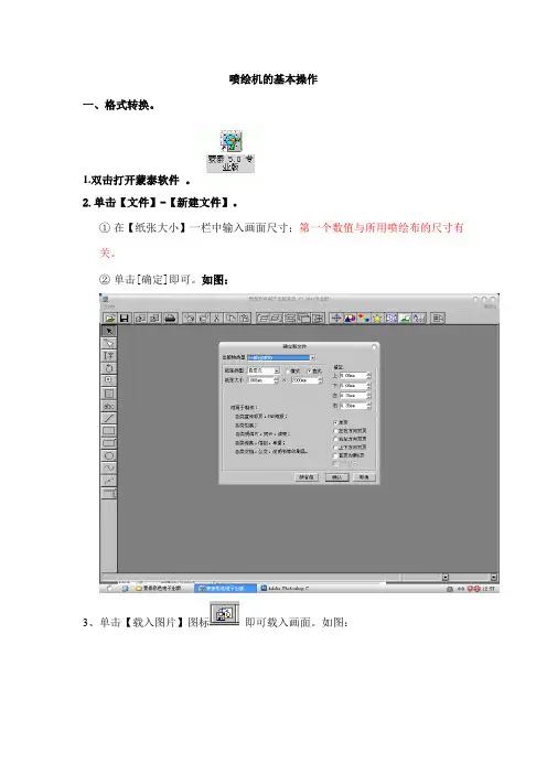
喷绘机的基本操作一、格式转换。
1.双击打开蒙泰软件。
2.单击【文件】-【新建文件】。
①在【纸张大小】一栏中输入画面尺寸;第一个数值与所用喷绘布的尺寸有关。
②单击[确定]即可。
如图:3、单击【载入图片】图标即可载入画面。
如图:4、调整画面尺寸。
①选中画面,右键点击调出属性对话框;如图②单击【栏框属性A】调出其对话框;双击依次双击【保持图片原尺寸】、【保持图片纵横比】,单击【确定】即可。
如图:5:调整坐标。
(使图片与文件框吻合)①单击[显示定位面板]图标;②先在中输入90;X:0 Y:=W的值。
如图:(注:每输入一个数值都要按一次回车键);;;;;;;;;;;;;;;;;;;;图一;;;;;图二;;;;;6、打印。
①单击【打印】图标,即弹出打印对话框。
如图②打击【打印机设定】调出其对话框双击【自动设置纸张】;单击【确认】即可。
如图:③输入文件名,单击【保存】即可。
如图:;;;;;;;;;;;;;;;;;;二、画面打印。
1.上布。
所上喷绘布要根据画面实际大小和喷绘布尺寸确定。
(喷绘一般左右留边个10cm;即净画面为100cm 则喷绘布为120cm)如图:2.开机。
开机顺序如图:(注:黑色三档控制键是控制松布与进布的,除打户外车贴外一般都向下按此键。
)3.吸墨头。
打开吸尘器的开关,左手拿着吸尘器的吸尘手柄(即黑色吸管)对着墨头依次吸墨,看到墨色被均匀吸出即可。
(顺序为****-红色-蓝色-黑色);注:①吸尘手柄的圆形末端要完全覆盖长方形墨头;;;;;;;②喷绘墨头因图片修改等问题不喷布时要每隔5分钟吸一次墨头。
如图:;4.打开软件。
双击电脑桌面上的Ultra720TH12 Control Center 软件的图标,启动该控制软件。
喷绘机喷头平台即缓缓左移。
碰到零位开关后,返回停在喷头清洗位置。
电脑桌面上出现该软件的主控图形界面,喷绘机平台初始化完成。
如图:5.测布。
①单击【测量】按键,调出【测量调板】。
软水器操作手册

Sensotrol III SG03 Operating InstructionsVersionSoftware/update Date Author RemarksLastCompleted 18.12.08Jm1 20.03.09JmadditionsSomestart-uptoAdditions2 29.04.09Jm345Contents1Introduction (5)1.1 Description (5)1.2 Notational conventions (5)1.3 Intended use (5)2Identification (6)2.1 Designation of the device (6)2.2 Scope of supply (6)2.3 Accessories (6)3Assembly (7)3.1 Mounting conditions (7)3.2 Dimensions (7)4Electrical connection (8)4.1 Wiring at a glance (8)4.2 Terminal layout (8)4.2.1 Cable specifications (9)4.3 Wiring diagrams (9)5Operation (10)5.1 Operating status (10)5.2 Operating modes (10)5.2.1 Sensor mode (10)5.2.2 Unattended operation in sensor mode (11)5.2.3 Regeneration (11)5.2.4 Brine formation (12)5.2.5 Standby (12)5.2.6 Volume mode (12)5.2.7 Time mode (12)5.3 Switching action (13)6Instructions for use (14)6.1 Operation at a glance (14)6.2 Display and control elements (14)6.2.1 LEDs (14)6.2.2 Keyboard (14)6.2.3 Function keys (15)6.3 Entering text and figures (15)6.3.1 Menu items (15)6.3.2 Data editing (16)6.3.3 Numerical data (16)6.3.4 Selectable data (16)6.3.5 Alphanumerical data (16)6.3.6 Time of the day (17)6.3.7 Calendar (17)6.3.8 Confirmations (17)6.4 Passwords (17)7Parameters and settings (19)7.1 User menu (19)7.2 Parameters menu (20)7.2.1 Description of the parameters (21)7.3 Technician level (22)8Operation of the installation by personnel (25)8.1 Changing the operating mode (25)8.2 Parameterisation of the capacity (26)8.3 Parameterisation of digital outputs (28)8.4 Parameterisation of digital inputs (30)8.5 Entering the degree of hardness (33)8.6 Entering day and time (34)8.7 Entering locking times (35)8.8 Setting forced regeneration cycles (36)8.9 Carrying out a reset (37)8.10 Setting the triggering factor (40)8.11 Setting the operating mode (41)8.12 Setting the emergency supply (42)8.13 Setting the conductivity limits (43)8.14 Setting the time limits (44)8.15 Measuring and calibrating (45)8.16 Diagnosis (47)8.17 Protocol (49)8.18 Start-up (51)8.19 Brine circulation pump (53)8.20 Recirculation pump (56)8.21 Liquid brine (59)8.22 Chip card (62)9Malfunctions and their elimination (64)9.1 Indication and acknowledgement (64)9.2 Description of and search for malfunctions (64)9.2.1 Lack of brine (64)9.2.2 Lack of capacity (65)9.2.3 Sensor defect (65)9.2.4 Flow meter defective (66)9.2.5 Insufficient rinsing (66)9.2.6 Lack of salt (67)9.2.7 Brine filling time (67)9.2.8 Below min. flow (67)9.2.9 Max. flow exceeded (68)9.2.10 External stop (68)9.2.11 Ext. emergency stop (68)10 Disposal (69)11 Technical Appendices (70)11.1 Technical data (70)11.2 Overview of the menu (71)11.3 Wiring diagram / sample connection (74)1 Introduction1.1 DescriptionThe Sensotrol control is a sensor-controlled device that can exactly determine the depletion degree of the ion-exchange resin and, based on this, trigger and carry out REGENERATION. The controller can also be used for volume or time controlled regeneration.1.2 Notational conventionsThe following abbreviations are used throughout this manual:Lim LimitCD ConductivityT Temperaturet Time/Durationhigh Output or input not actuatedlow Output or input actuatedThe following representations are used throughout this manual:Type:Font:Example:Keys: capitals + bold LEFT, UP, DOWNLEDs: capitals + bold OPERATION,MALFUNCTION/FAULTInputs/outputs, inlets/outlets: capitals + bold INLET VALVEOperating parameters: italics cond.raww., water volum eOperating status: capitals + underlined SENSOR MODE, VOLUMEMODE, TIME MODE Operating modes: capitals + underlined OPERATION, REGENERATION Malfunctions:capitals + underlined SENSOR DEFECT1.3 Intended useThe device is intended to control sensor operated water softening units in non explosion-prone areas.• The device has been designed for top mounting and may only be operated if mounted accordingly.• The manufacturer is not liable for damages resulting from improper or unintended use.Improper or unintended use may turn the controller into a hazardous device.2 Identification2.1 Designation of the deviceCompare the nameplate at the right side of the device to the bill of materials and the following figure:EnthärtersteuerungTyp. Sensotrol III SG03S-Nr.: 00545377-AC38-xxxxElektrischer Anschluss: V/Hz 230/50Anschlussleistung: 25W2.2 Scope of supply• Device with terminal box• Cable glands:o 1 piece M20x1.5o 4 pieces M16x1.5o 4 pieces M12x1.5• Stopper:o 2 pieces M16x1.5o 3 pieces M12x1.5• Terminal block plan (inside the terminal box cover)• Operating instructions• Bill of materialsPlease inform your supplier if you notice that parts are missing.2.3 AccessoriesFor the Sensotrol control the following accessories are available:• PC-Visualisation• Ethernet-Interface module• Profibus-Interface module3 Assembly3.1 Mounting conditionsWorking temperature range: 0 to 35 °C (32 to 95 °F), humidity, non-condensing.Caution!• Please provide sufficient cooling of the installation in order to avoid heat accumulation. • Make sure there is sufficient distance to strong magnetic fields.• Environment according to protection category IP65.3.2 DimensionsThe controller is delivered inside a Bopla casing RCPM 2500 for top mounting (217x257x133 mm).4 Electrical connection4.1 Wiring at a glanceWarning!Note that the entire electric connection may only be carried out while the device is disconnected from the mains.Caution!• The protective earth connection must be carried out before any other connection. Danger may occur if the PE wire is interrupted.• Before performing the start-up, make sure that the supply voltage corresponds to the value indicated on the nameplate (right side of casing).• Combining low safety voltage and voltage presenting a risk of electrocution at the relays is not permitted.• For the mains line, an overcurrent protection (nominal current ≤ 16 A) is required.Note:Please also observe the terminals plan inside the terminal box cover.4.2 Terminal layoutTerminal Operation Type Comment1 230V phase 2230V neutral 3Supply voltagePESupply of the controller. (fuse: 4A)4230V phase 5 230V neutral 6Mains output PESupply of the switching outputs (fuse: 4A)7NC contact 8Root9Universal output 1 NO contact Voltage-freemax. 24VDC/1A, 250VAC/4A10PE 11No 12Operation valve of filter 1 BV1 Lo 24 VAC max. 300 mA13PE 14No 15 La 16 Lb 17 Pilot valve of filter 1 PV1 Lo 24 VAC max. 300 mA18 PE 19No 20 Operation valve of filter 2BV2 Lo 24 VAC max. 300 mA21 PE 22No 23 La 24 Lb 25 Pilot valve of filter 2PV2 Lo 24 VAC max. 300 mA26 Root27Universal output 2(Operation message) NO contact Voltage-freemax. 24VDC/1A, 250VAC/4A 28 Root29Universal output 3(Regeneration message) NO contact Voltage-freemax. 24VDC/1A, 250VAC/4A 30 Root31Universal output 4(error message) NO contactVoltage-freemax. 24VDC/1A, 250VAC/4ADistance (galv. isolation)32 Root33 Universal output 5(pulse output dosing pump) NO contact Open collector output 24 VDC max. 15 mA 34 Resin temp. 35 Resin temp.36 Resin conduct. A37 Resin conduct. B, water conduct. A38 Conduct. sensor water/resinfilter 1Water conduct. B39 Resin temp. 40 Resin temp.41 Resin conduct. A42 Resin conduct. B, water conduct. A43 Conduct. sensor water/resinfilter 2Water conduct. B44 GND45 Pulse input 46 Flow meter+24 VDC For Hall effect sensor or REED switch47 GND 48 Universal input 1 (lack of salt switch) Input For voltage-free contact 49 GND 50Universal input 2InputFor voltage-free contact4.2.1 Cable specificationsTerminalsCable min. Cable max.Cable typeSupply voltage 3x1.0 mm² 3x1.5 mm² NYM-J/Ölflex 110Mains output3x0.75 mm² 3x1.5 mm² NYM-J/Ölflex 110Universal output 13x0.75 mm² 3x1.5 mm² NYM-J/Ölflex 110Operation valve of filter 13x0.5 mm² 3x0.75 mm² Ölflex 110 Pilot valve of filter 1 5x0.5 mm² 5x1.0 mm² Ölflex 110 Operation valve of filter 23x0.5 mm² 3x0.75 mm² Ölflex 110 Pilot valve of filter 2 5x0.5 mm² 5x1.0 mm² Ölflex 110Universal output 2 2x0.5 mm² 2x1.0 mm² NYM-J/Ölflex 110Universal output 3 2x0.5 mm² 2x1.0 mm² NYM-J/Ölflex 110Universal output 4 2x0.5 mm² 2x1.0 mm² NYM-J/Ölflex 110Universal output 5 2x0.14 mm² 2x0.5 mm² LiYY/Ölflex 110 Conduct. sensor filter 1 6x0.14 mm² 6x0.34 mm² LiYCY Conduct. sensor filter 2 6x0.14 mm² 6x0.34 mm² LiYCY Flow meter3x0.14 mm² 3x0.5 mm² LiYY Universal input 1 2x0.14 mm² 2x0.75 mm² LiYY Universal input 22x0.14 mm²2x0.75 mm²LiYY4.3 Wiring diagramsIn the appendix you will find examples of the wiring configuration.5 Operation5.1 Operating statusFilters A and B can each have the following operating modes:• OPERATION• STANDBY• REGENERATION• ERROR (FAULT)The Sensotrol controller has been developed chiefly as a sensor control system which can be used to accurately establish depletion of the ion-exchange resin so that REGENERATION can be subsequently triggered and carried out. The controller can also be used for volume or time controlled regeneration.5.2 Operating modes5.2.1 Sensor modeA regenerated filter can be put into OPERATION immediately after REGENERATION. A depleted filter can not be put into OPERATION before it has been regenerated. In sensor mode, automatic adjustment takes place at the beginning of each operational phase whenever a volume of water in litres equal to three times the capacity in m³ · °d has passed through the filter. As long as the first adjustment of a filter has not been completed, the respective filter is displayed as greyed out on the screen. At the first commissioning the filters must be calibrated and the filters should be displayed normally on the screen. Conductivity in the resin bed (CDR) and in the soft water (CDW) is continuously calculated.The processor calculates the following triggering factor (TF) at short intervals:CDRTF = -------------- x 100JustCDRwhere CDRJust represents the resin conductivity during adjustment. The triggering factor during adjustment is therefore 100%. Tests have shown that conductivity decreases by about 35% when the resin changes from a regenerated to a depleted state. During complete depletion, resin conductivity is still at 65% of the level during adjustment and so the smallest possible triggering factor is TF = 65%.When water passes the filter, the control unit compares the momentary value of the triggering factor with a fixed value TF0 between 65 and 85% (generally 80%). If the triggering factor remains below the value TF0 (t-TF0) for five minutes then REGENERATION is initiated. The triggering criterion TC charts the course of the triggering factor between 100 % and the fixed value TF0 as a linear function for the range 100% to 0%, i.e. if levels go below the value TC=0%, then REGENERATION is initiated (after a five minute delay).If no water flows, the triggering criterion is no longer monitored. This means that a conductivity drift within the resin granule, caused by diffusion during stop times, cannot initiate the regeneration process. If the soft water conductivity (CDW) changes during OPERATION, then the conductivity in the resin bed (CDR) which activates regeneration must also change. The dependency CDR on the CDW has been shown in tests and is saved as a data record in the control unit. The value of CDRJust, which corresponds to the new value of CDW, can thus be calculated and used to determine the current triggering criterion.5.2.2 Unattended operation in sensor modeIn order to control the functioning of the flow meter, the last triggering criterion is kept until termination of the adjustment. If the FLOW METER is working, the new triggering criterion is applied upon termination of the adjustment.If the FLOW METER is defective, the adjustment is not completed due to the absence of the flow meter signal. When the triggering criterion is reached before termination of the adjustment, the controller recognises the FLOW METER to be defective.If the sensors are working, the installation OPERATES according to standard instructions.In case of a sensor defect, the soft water conductivity and/or the resin conductivity is not recorded. The controller recognises this and displays an error message.5.2.3 RegenerationIf the installation is run in volume or time mode, the regeneration is carried out according to an adjustable timetable for the duration of each regeneration step. The sensor mode combines a time-controlled process and monitoring of rinse water conductivity. The details of the procedure are as follows:1. Backwash (BW):This is carried out for a preset, fixed period of time (backwash t).2. Brine draw/slow rinse (BD/SR):During BRINE DRAW, there is a check to see whether the high conductivity of brine is registered on the water sensor within a preselectable time (brine wait. t). This high conductivity must then be measured for a second preselectable time (minimum time for the brine draw "min.t.brn.dr.") on the water sensor. If the criteria for this two-step brine test are not fulfilled, the LACK OF BRINE alarm is activated. The slow rinse stage continues until the rinse water conductivity lies constantly under 1,800 µS/cm (CD-SR) for a 60 second period. If this level of conductivity has not been reached once the set time (brine draw t) has come to an end, the process is stopped.3. Fast rinse:This is carried out for a preset, fixed period of time (fast rinse t). If the rinse water conductivity is still above 1,800 µS/cm (CD-FR) at the end of this time, the controls remain in fast rinse mode until the conductivity falls below this level and five more minutes have passed (LACK OF RINSING error).Once REGENERATION is completed, the regenerated filter is in STANDBY. Connecting a BRINE PUMP can reduce the time needed for brine formation (brine form t), which takes 300 minutes without a circulation pump, to about 60 minutes because of forced circulation in the brine tank. The BRINE PUMP is to be connected to the UNIVERSAL OUTPUT 1 (terminals 7, 8, 9). Set the brine formation time to 60 minutes (brine form t). During brine formation, REGENERATION can be initiated but not started. The delay (in minutes) until the start of the REGENERATION process is shown in the LCD.5.2.5 StandbyUpon termination of the REGENERATION the filter switches to STANDBY. A switch to OPERATION takes place when the other filter starts to REGENERATE.5.2.6 Volume modeREGENERATION is initiated depending on the volume, i.e., as soon as thesoft water volume (m³) = capacity (°dH x m³) / max. hardness (°dH)for the filter in operation is reached.Note!In the event that the FLOW METER is defective, it is possible that hard water enters the system. The FLOW METER is monitored in sensor mode only.5.2.7 Time modeRegardless of the depletion degree of the resin, a REGENERATION of the filter in OPERATION is initiated as soon as a defined time interval (to be defined in the technician level, forced regeneration has elapsed.Note!When the unit runs in time mode, the depletion degree of the resin is not detected. It is thus possible that hard water enters the system.Switching pointRegenerated resin Depleted resinConductivity Resin/WaterWater conductivityCD = Conductivity in the resin/water mixture Vs = soft water amount produced 80 % = triggering factor6 Instructions for use6.1 Operation at a glanceThe controller is easy to understand and allows commissioning the unit almost without the operating manual for many applications. The start-up wizard will guide you through all of the important settings as soon as the device has been switched on.It shows the setting limits and standard settings for the respective parameters on the screen. Below these you will find explanations on the controller for the elements that are not clearly described through text or by selection lists. We reserve the right to make changes that serve technical progress.6.2 Display and control elementsThe operator interface consists of a graphic display (128x64 pixel), 7 keys and an LED for OPERATION and FAULT each. It also has an acoustic alarm.6.2.1 LEDsThe LEDs show the installation's status OPERATION (green) and FAULT (red).6.2.2 KeyboardThe controller is operated by 4 cursor keys and 3 function keys (F1, F2, F3). The cursor keys have the following functions:Î (RIGHT) Selection of one decimal place within an edit fieldÍ (LEFT) Selection of one decimal place within an edit fieldÏ (UP) Menu selection, option selection, selection of one digit within an edit fieldÐ (DOWN) M enu selection, option selection, selection of one digit within an edit fieldF1 (ESC) Function key 1 (often used as ESC key)F2Function key 2F3 (ENTER) Function key 3 (often used as ENTER key)6.2.3 Function keysOperation is mainly carried out with the function keys (F1, F2, F3). The functions of the keys are indicated through the icons in the lower display section.The icons that are most frequently used are shown below:Terminate function/menu, abort setting (= ESC)Select function/menu, save setting (= ENTER)Answer "yes" to a questionAnswer "no" to a questionDisplay report menuDisplay settings menu6.3 Entering text and figures6.3.1 Menu itemsThe menu consists of several items in a list (arranged one below the other) that can be longer than the number of items displayed on the screen.A menu item is selected with the arrow on the left side of the screen. The arrow is moved with the UP and DOWN keys and moved to the menu item of your choice. The marked menu item is then selected with the F3/ENTER key. If the list of menu items is longer than the part displayed on the screen, the controller scrolls automatically.Note:• Most of the menus have a hierarchical structure, i.e., upon selection of a menu item, another submenu opens.• You can usually leave a menu by pressing the F1/ESC key (return to normal level).6.3.2 Data editingData are normally edited via a special screen, where the parameters, their admissible value range and the standard value are shown.Any editing process may be aborted without saving the changed value by pressing F1 (ESC). When editing parameters, there is differentiation between the following five data types:6.3.3 Numerical dataNumerical editing is carried out to adjust the operating parameters and to set the calibration parameters. Numerical editing works like programming a decade switch.The digit to be changed is selected with the cursor (a block in the display) and set to the desired value by pressing the UP / DOWN keys as often as necessary. By means of the LEFT / RIGHT keys, the cursor can be moved to the other digits so that these can be modified as well. The value indicated is stored using the F3 (ENTER) key.6.3.4 Selectable dataIn some cases an option can be selected (operating modes, operating statuses). Upon selection of the option, the operator can scroll through all further options with the UP / DOWN keys. The displayed selection is confirmed with the ENTER key.6.3.5 Alphanumerical dataThe message texts can be edited alphanumerically. The procedure is identical to that of numerical editing, but it is possible to select numbers and characters with the UP and DOWN keys.6.3.6 Time of the dayEditing is carried out as described for numerical data, but a time in the HH:MM format is selected. It is possible to edit any time from 00:00 to 24:00 (the 24 h mode allows definition of a complete one-day time span). .The adjustment to summertime or wintertime is carried out automatically.6.3.7 CalendarEditing is carried out as described for numerical data, but a date in the DD:MM:YY format is selected. The year is set with only two digits (20xx is assumed).6.3.8 ConfirmationsFor safety reasons and to avoid erroneous settings, some functions require confirmation. The following screen is used for this purpose.By confirming with F3/Enter the selected function is carried out. By pressing F1/Esc the function is aborted.6.4 PasswordsThe different menus, functions and settings are accessible via 4-digit, numerical passwords. The following two hierarchical access levels are differentiated.Access level Name oflevelPresetpasswordPassword necessary for...1 User level 1234 user and parameter levels3 Technicianlevel3456 technician level and sublevelsThe password for the level indicated on the screen (or superior level password) must be entered and confirmed with F3/Enter.If a wrong password is entered or if the password entry is aborted with F1/Esc, the access is denied.Note:• The passwords can be changed in the parameter menu and in the technician level.• It is possible, when a password is asked for, to enter the password of a higher level. Since the access to the superior level is granted until the menu is exited, passwords will not have to be re-entered if additional functions carried out.7 Parameters and settings7.1 User menuMenu Parameter Format/Unit Selection/LimitsDefault setting U1 InformationU1.1 Total amount filter 1 xxxx m³< Q tot filter 1 > ---U1.2 Total amount filter 2 xxxx m³< Q tot filter 2 > ---U1.3 Max. amount filter 1 xxxx m³< Q max filter 1 > ---U1.4 Max. amount filter 2 xxxx m³< Q max filter 2 > ---U1.5 Conduct. raw water filter 1 xxxx µS/cm< CDW filter 1 > ---U1.6 Conduct. raw water filter 2 xxxx µS/cm< CDW filter 2 > ---U1.7 Conduct. resin filter 1 0 - 1024< CDR filter 1 > ---U1.8 Conduct. resin filter 2 0 - 1024< CDR filter 2 > ---U1.9 Type <Sensotrol> ---U1.10 Language -Deutsch- English- Français- Italiano- Nederlands- E spañol Deutsch (German)U1.11 Audio signal - Off- OnOff U1.12 Software version < > --- U1.13 System version < > --- U1.14 Param. version < > --- U1.15 Calib. version < > ---U1.16 Autom.Summer/Wintertime - Off- OnOnU1.17 Start of summer time < > --- U1.18 Start of winter time < > --- U2 Operating modeU2.1 - Operation filter 1- Operation filter 2- Regen. filter 1- Regen. filter 2--- U3 System timeU4 Parameters Access to the parameter level7.2 Parameters menuMenu Parameter Format/unit Selection/limitsDefault setting P1 Locking time AP1.1 Start 00:00–00:0000:00–24:00 00:00P1.2 End 00:00–00:0000:00–24:00 00:00P2 Locking time BP2.1 Start 00:00–00:0000:00–24:00 00:00P2.2 End 00:00–00:0000:00–24:00 00:00P3 Forced regeneration xx d00–99 00P4 Hardness rangeP4.1 °dH min xx.x °dH0.0–99.9 5.0P4.2 °dH max xx.x °dH0.0–99.9 40.0P5 Operating mode - Sensor mode- Volume mode- Time mode Sensor operationP6 Emerg. supply - Hard water- Switch offSwitch offP7 Conduct. limits (super password will be asked for when modifying data)P7.1 cond.brine_wait xxxxµS/cm600–800 600P7.2 condct.slow rns xxxx µS/cm1000–2000 1800P7.3 condct.fast rns xxxx µS/cm1000–2000 1800P7.4 dct.sensor xxxµS/cm0–100 20P7.5 dct.sensr xxxxµS/cm2000–50005000 P8 Time limits/param.P8.1 backwash t xx min2–30 9P8.2 brine draw t xxx min60–180 120P8.3 fast rinse t. xx min5–30 19P8.4 brine form t xxx min0–500 300P8.5 brine wait. t xx min2–50 40P8.6 min.t.brn.dr. xxxmin5–50 10P8.7 cond.brine_wait xxxs5–999 60P8.8 brine fill. t xx min5–99 30P9 Technician level Access to the technician levelP10 User password 4-digit code0000–9999 12347.2.1 Description of the parameters• P7.1 brine wait. t: the scaled conductivity value of the water that must be reached for the period P8.5 during the brine draw regeneration step is displayed.• P7.2 condct.slow rns: the scaled conductivity value of the water that must be reached for the period P8.7 during the slow rinse regeneration step is displayed (downscaled).• P7.3 condct.fast rns: water conductivity value that the measured value must fall below during the regeneration phase fast rinse.• P7.4 dct.sensor and P7.5 dct.sensr: limits of the measuring range of the conductivity probe.• P8.1 backwash t: duration of the regeneration phase backwash.• P8.2 brine draw t: max. duration of the regeneration phase brine draw.• P8.3 fast rinse t.: min. duration of the regeneration phase fast rinse• P8.4 brine form t: time set for brine formation.• P8.5 brine wait. t: period of time during which the high conductivity value of the brine (P7.1) must be detected during the regeneration phase brine draw.• P8.6 min.t.brn.dr.: min. duration of the regeneration phase brine draw.• P8.7 t cd.low sl.r: min. period of time during which the conductivity must be below the limit (P7.2) during the regeneration step slow rinse• P8.8 brine fill t.: max. time for the filling of the liquid brine tank.7.3 Technician levelDefault setting Menu Parameter Format/Unit Selection/LimitsS1 InputsS1.1 pulse input xxx.xx pulse/l0.01–999.99 34.50NOCS1.2 univ.DI1 logic - NC contact- NO contactS1.3 univ.DI1 func. - permanentpermanent- pulselack of saltS1.4 univ. DI1 text Freely programmablemessage textS1.5 univ.DI1reaction - no reactionno reaction- message only (analogous to"1" in the malfunction matrix)- emerg. switch-off (NAZ)- system off- suppressionregeneration- initiationregeneration- brine fillingS1.6 univ. DI1 active - alwaysalways- stand-by- operation- backwash- brine draw/slow rinse- fast rinse- hard water production if lackof capacity- lock iflack of capacity- error stop- locking time- below min. flow- no flow- lack of brine- sensor defect- lack of cap.- lack of rinsingS1.7 univ. DI1 delay xxx s0–999 0S1.8 univ. DI2 logic analogue univ.dig. input1S1.9 univ.DI 2 func. analogue univ.dig. input1S1.10 univ. DI 2 text analogue univ.dig. input1S1.11 univ.DI2reaction analogue univ.dig. input1S1.12 univ. DI2 active analogue univ.dig. input1S1.13 univ. DI2 delay analogue univ.dig. input1Menu Parameter Format/Unit Selection/Limits Default settingS2 OutputsS2.1 univ. DO1 - stand-by F1- operation F1- backwash F1- brine draw / slow rinse F1- fast rinse F1- standby F2- operation F2- backwash F2- brine draw / slow rinse F2- fast rinse F2- error stop- system off- recirculation- brine recirc.- brine filling- lack of brine- hrd w.if low cap- l ock if low cap.- locking time- no flow- sensor defect- lack of cap.- lack of rinsing- univ.dig. input1- univ.dig. input2 0 / P / I0 / P / I0 / P / I0 / P / I0 / P / I0 / P / I0 / P / I0 / P / I0 / P / I0 / P / I0 / P / I0 / P / I0 / P / I0 / P / I0 / P / I0 / P / I0 / P / I0 / P / I0 / P / I0 / P / I0 / P / I0 / P / I0 / P / I0 / P / I0 / P / IS2.2 univ. DO2 analogous to univ. DO1S2.3 univ. DO3 analogous to univ. DO1S2.4 univ. DO4 analogous to univ. DO1S2.5 funct. univ. DO5 - 0 / P / I- pulse output/IS2.6 *pulse output/I xx.xx pulse/l0.01–99 1S2.7 °univ. DO5 analogous to univ. DO1S3 Sensor type - d32/d50- ¾"d32/d50 S4 Capacity xxxx m³ °dH20–10.000 200S5 Max. flow xx.xx m³/h0.01–99.99 20.00S6 Recirculation xx.xx m³/h0.01–99.99 0.05S7 TF0 (triggering factor) xx %65–90 80S8 t-TF0 (delay TF0) xxx s 0–999 300S9 Meas./calibr.S9.1 CDW1 µS/cm Input of actual valueS9.2 CDW2 µS/cm Input of actual valueS9.3 calibrate analogue input (super passwordrequested)Calibration of curves。
关键性设备操作手册.doc
1.锚缆机操作规程----------------------------------------------------------------4 2.首尖舱污水遥控排水系统操作规程-----------------------------------------6 3.压载控制台操作规程-----------------------------------------------------------74. 货舱进水检测装置操作规程--------------------------------------------------95. 货舱污水处理操作规程--------------------------------------------------------116.报警监视系统操作规程--------------------------------------------------------127. 和面机/电炒锅操作规程------------------------------------------------------ 148. 电灶的使用与保养--------------------------------------------------------------159.粉碎机操作规程-----------------------------------------------------------------1610.烤箱的操作规程-----------------------------------------------------------------1711. 蒸馒头/蒸饭机的操作规程------------------------------------------------------1812. 货舱作业的安全规定----------------------------------------------------------1913. 甲板作业的安全规定---------------------------------------------------------2014. 开关舱作业的安全规定------------------------------------------------------2115. 系解缆作业的安全规定------------------------------------------------------2216. 舷外、水上作业的安全规定------------------------------------------------2417. AIS操作规程-------------------------------------------------------------------2518. C站操作规程-----------------------------------------------------------------2719. EPIRB 操作规程---------------------------------------------------------------2820. F站操作规程-----------------------------------------------------------------2921. GPS NAVIGATOR操作规程--------------------------------------------------3022. NAVTEX 操作规程-------------------------------------------------------------3323. NBDP 操作规程----------------------------------------------------------------3424. VDR 操作规程------------------------------------------------------------------3625. VHF 操作规程------------------------------------------------------------------3726. 电子海图操作规程------------------------------------------------------------3827. 雷达使用操作规程------------------------------------------------------------3928. 气象传真机操作规程---------------------------------------------------------4429. 自动舵操作规程---------------------------------------------------------------4730. 驾机联系制度------------------------------------------------------------------4831. 驾驶台规则---------------------------------------------------------------------5132. EEBD 操作规程----------------------------------------------------------------5233. 火警控制面板操作规程-----------------------------------------------------5334. 机舱大型二氧化碳灭火系统操作规程-----------------------------------5435. 机舱水雾灭火系统操作规程-----------------------------------------------5536. 救生筏释放程序--------------------------------------------------------------5637. 救生艇操作规程--------------------------------------------------------------5738. 消防员装备操作规程--------------------------------------------------------5839. 机炉舱规则--------------------------------------------------------------------6040. 机舱值班制度-----------------------------------------------------------------6241. 检修作业注意事项-----------------------------------------------------------6642. 主机操作规程-----------------------------------------------------------------6743. 副机操作规程-----------------------------------------------------------------6944. 燃油锅炉操作规程-----------------------------------------------------------7045. 主空压机操作规程-----------------------------------------------------------7246. 空调装置操作规程-----------------------------------------------------------7347.燃油分油机操作规程--------------------------------------------------------7448. 滑油分油机操作规程--------------------------------------------------------7549. 主机滑油泵操作规程--------------------------------------------------------7650. 主机缸套水泵操作规程-----------------------------------------------------7751. 主海水泵操作规程-----------------------------------------------------------7852. 重油驳运泵操作规程--------------------------------------------------------7953. 造水机操作规程--------------------------------------------------------------8054. 油水分离器操作规程--------------------------------------------------------8155. 生活污水处理装置操作规程-----------------------------------------------8256. 应急发电机操作规程--------------------------------------------------------8357. 应急救火泵操作规程--------------------------------------------------------8458. 应急空压机操作规程--------------------------------------------------------8559. 冰机操作规程-----------------------------------------------------------------8660. 焚烧炉操作规程--------------------------------------------------------------8764. 主配电板操作规程-----------------------------------------------------------8865. 应急配电板操作规程--------------------------------------------------------89 63. 压载泵操作规程--------------------------------------------------------------90目录64. 消防通用泵操作规程---------------------------------------------------------9165. 污水泵操作规程---------------------------------------------------------------9266. 机舱电力中断应急操作------------------------------------------------------9367. 触电的预防和急救------------------------------------------------------------9568. 总用电瓶及充放电板操作规程---------------------------------------------9669. 机舱报警检测系统操作规程------------------------------------------------9770. 机舱局部灭火系统操作规程------------------------------------------------9871. 机舱水雾灭火系统高压泵操作规程---------------------------------------9972. 主机机侧应急操作规程------------------------------------------------------10073. 主机盘车机操作规程---------------------------------------------------------10174. 饮水消毒柜操作规程---------------------------------------------------------10275. 砂轮机操作规程---------------------------------------------------------------10376. 气焊作业安全规定------------------------------------------------------------10477. 电焊作业安全规定------------------------------------------------------------10578. 车床作业安全规定----------------------------------------------------------10679. 救生艇机操作规程------------------------------------------------------------10780. 油渣泵操作规程---------------------------------------------------------------10881. 钻床作业操作规程------------------------------------------------------------10982. 火警T1016控制面板操作规程---------------------------------------------11083. 舵机操作规程------------------------------------------------------------------112锚缆机操作规程O P E R A T I O N I N S T R U C T I O N S F O R M O O R I N G W I N C H&W I N D L A S S 一、绞缆机操作的注意事项1)操作前必须要检查以下事项:●离合器的位置,齿轮箱上档位杆的位置,传感器上的指示灯,●检查刹车杆及刹车带是否完好,工作是否正常,●缆绳的出绳方向是否与刹车带底部连接块侧一致,●检查滚筒转动方向是否与操作杆指令方向一致,●检查所有的油脂润滑点,油位是否符合要求。
SMT钢网自动清洗机操作指导书
SMT钢网自动清洗机操作指导书(ISO9001-2015/ISO45001-2018)一、开机前检查1、检查进气压力是否在0.45MPa~0.75MPa2、打开电源接接通排风管(将¢120mm的排风管接至室外)。
3、利用自动加、排液系统,使储液箱内加入足够的液体(≦35L)4、据需清洗的网板尺寸调节好网板固定治具。
二、操作步骤1、观察控制面板各元件显示状态,气源指示灯(AIR)显示绿色,表示正常;若为红色,表示气压不足或无压缩空气.(需调节气压至正常工作压力)2、打开门将需清洗的网板放入清洗室内,确认放好后,关闭清洗室门。
此时观察控制面板上的(DOOR)指示灯,显示绿色即可正常启动工作,红色表示门未关好,机器将无法启动工作。
3、清洗时间设定:打开清洗时间控制器防护盖,按箭头方向按下白色按键(时间设置锁定键),同时分别调节右方三个黑色按键,设定好所需时间后松开白色按键,关闭防护盖.此时设定的时间就被锁定。
时间单位为秒(5个9的除外),一般清洗时间设置为240-999秒范围内。
4、干燥时间设定:打开干燥时间控制器防护盖,按箭头方向按下白色按键(时间设置锁定键),同时分别调节右方三个黑色按键,设置好所需时间后松开白色按键,此时设定好的时间就被锁定。
一般干燥时间设置为400-600秒范围内。
5、调整急停按键(EMERGENCYSTOP)处于复位状态。
6、按下启动键(START),设备被启动.清洗控制器开始计时,同时开始清洗钢网.清洗时间到达后自动切换至干燥控制器,干燥控制器开始计时,并且开始干燥.干燥时间到达后,工作结束,计时器停止计时,同时机器也停止工作.7、打开门,机器自动复位,取出钢网,一次清洗流程结束。
三、注意事项:1、机器在正常工作情况下,需每周添加一次清洗剂;2、注意查看机器右下方窗口处清洗液位置的高度,如果液位低于M,就需要及时添加液体进去;3、注意各个气泵出入口阀门的用途,请勿随便打开阀门。
微孔过滤器使用方法说明书

微孔过滤器使用方法说明书1. 简介微孔过滤器是一种常用的过滤设备,能够有效去除液体中的微小颗粒物质。
本使用方法说明书旨在帮助用户正确使用和维护微孔过滤器,以确保其长期正常运行并获得最佳过滤效果。
2. 设备组成微孔过滤器主要由以下几部分组成:- 过滤器外壳:通常为不锈钢或塑料材质制成,具备较强的耐腐蚀性和抗压能力。
- 过滤介质:包括微孔滤芯和支撑网等,用于截留微小颗粒物质。
- 进出口接口:用于连接管路,使液体能够顺利通过过滤器。
3. 使用前准备在开始使用微孔过滤器之前,请确保以下准备工作已完成:- 检查过滤器外壳是否完好,如有破损或渗漏,请及时更换或修复。
- 清洗过滤器外壳及过滤介质,确保其表面无杂质。
- 确认过滤器进出口接口与管路连接紧密,避免漏液或渗漏。
4. 使用步骤按照以下步骤正确使用微孔过滤器:4.1 打开进水阀门:将待过滤的液体通过管路引入微孔过滤器,打开进水阀门,保持液体稳定流动。
4.2 调节压力:根据具体需求,调节进水阀门和出水阀门以控制液体通过过滤器的压力。
4.3 监测过滤效果:观察液体通过过滤器后的透明度变化,若有异常情况,请及时检查和维护过滤器。
4.4 关闭出水阀门:待过滤液体通过过滤器后,请关闭出水阀门,停止液体流出过滤器。
4.5 清洗过滤器:当过滤器内部积存颗粒物较多时,需进行清洗。
关闭进水阀门,将过滤器拆下,并用清水冲洗,清除其中的杂质。
注意:清洗时请佩戴手套,防止对皮肤造成伤害。
4.6 安装回位:清洗完毕后,请将过滤器安装回位,并确保连接紧密,防止漏液。
5. 维护保养为了延长微孔过滤器的使用寿命和保证过滤效果,请定期进行以下维护保养工作:- 定期清洗过滤器:根据使用情况,定期检查过滤器内部的积存物,并进行清洗。
- 定期更换过滤介质:根据过滤器性能和使用情况,定期更换过滤介质,保证其过滤效果。
- 定期检查外壳密封性:确认过滤器外壳密封性良好,避免液体泄漏和降低过滤效果。
6. 注意事项- 在操作过程中,注意个人安全,避免接触过滤器内部液体,避免对皮肤和眼睛造成损害。
阿米亚德自清洗过滤器使用说明书.
6.过滤器必须安装完整,以避免水花溅落到电力元件或控制盘上。
7.如果安装在热水场合,请额外附加一些安全装置以避免烫伤皮肤。
操作、控制与维护
1.在调试、安装过滤器之前应切断电源供应。
2.只有在压力释放之后才能松开或拆卸螺栓。
3.缓慢地打开进口阀门,如果可以,请保持出口阀关闭且旁通阀打开,按下“TEST”按钮操作手动清洗。
4.缓慢打开出口阀门使过滤器逐渐达到正常工作流量。
5.清洗操作应该持续大约16秒,并且可以观察到整个过程中排污阀应该完全开放,16秒过后,排污阀应能立即关闭。确保清洗完全结束后排污阀没有明显的泄漏。
电动控制系统说明
3.方便地靠近过滤器。
4.工作一周以后检查并重紧螺栓。
安装示意图:
备注:标注尺寸:毫米
1.8″CBR线外型过滤器
2.2″排污管
3.8″止回阀
4.8″进口蝶阀
5.8″旁通阀
*打开过滤器所需最小尺寸。
安装示意图:
备注:标注尺寸(毫米)
1.4″CBR型过滤器
2.2″排污管
3.2″排污阀
4.4″止回阀
5.4″进口蝶阀
04
1 1 0 0
12秒
05
0 0 1 0
20分钟
05
0 0 1 0
16秒
06
1 0 1 0
30分钟
06
1 0 1 0
20秒
07
0 1 1 0
45分钟
07
0 1 1 0
25秒
08
1 1 1 0
1小时
08
1 1 1 0
30秒
【三星贴片机操作指引】
作成 审核批准管控章一、 目的及其适用范围建立贴片机作业规范,作为操作人员的作业依据,以达到作业质量一致,安全操作之目的。
适用本公司SMT 车间三星SM421操作 二、 操作方法2.1启动设备前的检查:检查设备周围的安全状况,设备内部有无杂物。
2.2打开主气源与电源2.3打开设备电源:顺时针方向拧设备前面的Main 开关,给设备供应电源。
2.4检查气压是否正常,气压:4.5-5.5kg/cm 2 2.5操作面板介绍。
(如下图)2.6待设备进入操作软件界面后点击操作面板上的F/R SELECT-LOCK 键,再点击Servo free 键,按键LED 灯亮时,表示伺服已解锁。
2.7设备原点复位:点击界面上的 应用 —暖机—输入暖机时间(10分钟)及使用设定的暖机时间项打勾—开 始。
2.8根据所生产的机型打开主界面左下方“打开”的文件夹,选择相应机型贴片程序文件名(文件格式OPT )。
2.9调整轨道宽度及摆放顶针(生产双面板时顶针摆放不能顶到元件)。
2.10打开程序后点击:喂料器—只显示已设定的喂料器项打勾—按照程序排好的站位装送料器—核对料站— —填写换料记录。
2.11生产运行:进入主界面点击,生产—完成—PCB 板下载—开始—START 键。
2.12暂停生产:在设备运转中,单击红色STOP 键可以使设备停止运转,重新单击START 键则可重新开始 生产。
START :开始键Servo free:伺服解锁键STOP :暂停、停止键F/RSELECT-LOCK 前后面板切换键RESET 复位键FEEDERCHANG E:送料器切换键EMERGEN CY:紧急按键。
写 真 机 操 作 手 册
写真机操作手册编辑:技术部面板主菜单说明:1. 装载打印载体(测量纸张大小)2. 切割(无用)3. 暂停(当机器打图时,喷头断线或其他问题时按此键暂停)4. 重新设置(当机器工作中想终止工作时按下此键)当按下“5馈送载体”键后,屏幕显示:馈送载体菜单:Array说明:此菜单是对载体进行装载操作,可选择“进”或“退”,按“退出”回到主菜单。
当按下“6 设置菜单”后,屏幕显示:设置菜单:说明:一般情况下C,E,F项不能随便更改,建议保持默认数值不变。
当选择A菜单时,屏幕显示:说明:各项设置如下:彩色模式(选“彩色”)优质模式(选“使用者自定”)英寸点数(选“600”或“300”,建议选:“600”)每行喷印次数(选“六”次)托架速度(即小车的行走速度,选“7”或“8”次)打印方向(选“双向”). 1 .当选择B 菜单时,屏幕显示:说明:各项设置如下:打印载体类型(选“卷轴或自动收卷”)打印载体标准(选“全部”)页边留白(选“正常”或“扩展”,建议选择“扩展”)自动装载延迟(选“6”)自动切割(选“关”)节省打印载体(选“开“)自动擦墨(选“开”或“关”)C 菜单用户勿须设定!!!当选择C注意:非专业人员..以上各项禁止随意改动。
当选择D 时,屏幕显示:说明:各项设置如下:选择使用者设定(把使用者选定的菜单设置保存在“1—8”中任意一项中)保存使用者设定(所需项选顶后必须保存在“使用者设定菜单”中选定的那一项中)计量单位选择(选“公制”)语种(选“中文”)初始设定值(勿动)打印设定值(勿动)液晶显示对比度(根据实际情况)当选择“7辅助功能菜单”时,屏幕显示:说明:各项功能如下:清洗(用于清洗喷头出墨是否正常)存取墨水匣(打印过程中用于对喷头进行抽墨等操作)颜色校准菜单(用于喷头的校正)选择“颜色校准菜单“时,屏幕显示:青色垂直/水平(根据校准打印测试来定制)品红色垂直/水平(根据校准打印测试来定制)黄色垂直/水平(根据校准打印测试来定制)选择“校准菜单“时,屏幕显示:校准菜单. 3 .选择“颜色静区菜单“时,屏幕显示:静区的数值(根据测试的值来定). 4 .喷头的校正一、喷头的校正分两步1. 颜色的静区校正,具体方法如下:主菜单里选择“辅助功能菜单”“校准菜单”“颜色静区菜单”“颜色静区测试”即在纸上打印出颜色静区测试条2. 颜色的水平垂直校正主菜单里选择“辅助功能菜单”“颜色校准菜单”“校准打印测试”即在纸上打印出颜色校准测试条,二、图纸纵轴线测试主菜单里选择“辅助功能菜单”“颜色校准菜单”“图纸纵轴线测试打印”即在纸上起始端开始走纸,默认参数为:83.82cm. 如果打完偏大或偏少此数值则用打印的实际数值代替原有的数值.注:默认参数83.82CM不会随更改数值所改变.. 5 .蒙泰软件安装及设置电脑设置:一在CMOS中对打印端口进行设置:重启电脑,在电脑进行硬件自检时按DEL键进入CMOS设置,进入INTEGRATED PERIPHERALS 功能选项,将其中的Parallel Port Mode 设置为ECP(注意:一定要是标准ECP,而不能是EPP、SPP 或者ECP/EPP),最后保存并建出BIOS设置,随后,电脑会重新启动,WINDOWS系统自动检测到ECP 打印口并为其安装驱动程序,这时,您就可以使用ECP打印口所提供的高速传输性能了。
海德堡自动清洗装置的使用方法
清洗 液 (洗 皮 水 )。 清 洗 过 程 中操
1
洗 墨 刮 刀 前 的 清 洗 液 喷 洒 次 数
4~8次
作 者 通过 判 断 橡 皮 布 表 面 清 洗 质量
2 i
洗 墨 刮 刀 前 的 机 器 转 数
3
清 洗 液 剂 量 与 清 洗 转 数
d
清 洗水 (蒸 馏水 )剂 量 与 清 洗 转 数
.。
,
*
蒜 一 : ……。0
,
= - : ::::::¨
‘
一■ 一
一
清洗 参数的设定
首先 通 过 海 德 堡CP2000操 作 系
统 界 面 ,选 择 自动 清洗 操 作 界 面 菜
图1墨辊清 洗程 序修改选择
鲢 ■■■■■鳖■■■●■一■■_: i :: !
口 j
品 质 量 与 市 场 竞 争 力 , 实现 更短 的 要 包 括3部 分 ,即 墨辊 、水辊 、印版 际 生 产 中 建议 使 用一 组 理 想 数 据 且【
印 刷 准 备 时 间与 更 少的 材料 消 耗 , 部 分 ,橡 皮 布 部 分 以 及 压 印 滚 筒 部 可 。墨 辊 清 洗 操 作 界 面 如 图 1和 图:
1
清 洗 液剂 量 与清 洗 转 数
10~ 1 3转 50% 剂 量
橡 皮 布 清 洗 基 本 一 致 ,使 用 同 种 清
—
—
—
2
清洗水 (蒸馏 水)剂量 与清洗转数
6~8转 /40% 剂量
洗 液 ,在 每 一 个活 件 印 刷 完 成 后 与
橡 皮 布 清 洗 同步 自动 清 洗 即 可 ;特