
实验报告静态路由-
计算机工程学院
实验报告书
课程名:《网络管理技术》
题目:实验三静态路由配置
班级:Z计121
学号: 2
姓名:
评语:
成绩:指导教师:
批阅时间:年月日
一、实验目的:
在使用CISCO 或HUAWEI-3COM 路由器模拟的广域网环境中配置静态路由,实现不同网络的相互访问。
二、实验内容
按下图要求配置静态路由,实现不同网络的相互访问。
(1) 在指定拓扑结构的多个路由器上配置静态路由; (2) 使用静态路由的常用查看命令; (3) 使用静态路由的常用测试命令
R3
R1
R2 S1/2
S1/2
F1/0
F0/0或F1/0
22.0.0.1/24
22.0.0.2/24
33.0.0.2/24
33.0.0.3/24
三、实验步骤
(1)修改三台计算机的ip地址后三台计算机互ping:
(2)通过telnet命令进入路由器控制界面中并show run 查看已有配置:
(3)配置静态路由:
①R1:
②R2:
③R3:
(4)使用Show ip route命令查看静态路由表①R1:
②R2:
③R3:
四、测试数据与实验结果
在完成配置后,Ping全网中任意网段都可以通,说明配置成功:(1)R1:
(2)R2:
(3)R3:
五、结果分析与实验体会
通过本次实验我掌握了:
(1)静态路由是在路由器中设置的固定路由表。
而动态路由是网络中的路由器之间的相互通信,传递路由信息,利用收到的路由信息更新路由器表的过程。
(2)①配置静态路由的命令常用格式:ip route 目的网络子网掩码下一跳路由器的IP
②查看静态路由表命令:show ip route
③路由器端口IP配置后要记得no shut down。
静态路由配置实验报告

静态路由配置实验报告篇一:计算机网络实验报告静态路由配置实验报告八班级:姓名:学号:实验时间:机房:组号:机号:PC_B一、实验题目静态路由配置二、实验设备CISCO路由器,专用电缆,网线,CONSOLE线,PC机三、实验内容? 了解路由的功能? 在CISCO路由器上配置和验证静态路由? 配置缺省路由四、原理静态路由是指由网络管理员手工配置的路由信息。
当网络的拓扑结构或链路的状态发生变化时,需要手工去修改路由表中相关的静态路由信息。
静态路由信息在缺省情况下是私有的,不会传递给其他的路由器。
静态路由一般适用于比较简单的网络环境,在这样的环境中,易于清楚地了解网络的拓扑结构,便于设置正确的路由信息。
五、实际步骤1.设置PC_B的IP地址,连接路由器,打开超级终端。
2.路由器B的配置User Access VerificationPassword:5_R2>enPassword:5_R2#conf tEnter configuration commands, one per line. End with CNTL/Z. 5_R2(config)#int s0/1/05_R2(config-if)#no shut5_R2(config-if)#interface s0/1/05_R2(config-if)#ip addr% Incomplete command.3.配置routerB的s0/1/0端口的IP地址5_R2(config-if)#ip address 172.17.200.6 255.255.255.2525_R2(config-if)#^Z4.配置路由器routerB的f0/1端口的IP地址5_R2#conf tEnter configuration commands, one per line. End with CNTL/Z. 5_R2(config)#int f0/15_R2(config-if)#ip address 10.5.2.1 255.255.255.0 5_R2(config-if)#^Z5.配置路由器routerB的f0/0端口的IP地址5_R2#conf tEnter configuration commands, one per line. End with CNTL/Z. 5_R2(config)#int f0/05_R2(config-if)#ip addr 10.5.4.1 255.255.255.05_R2(config-if)#no shutdown5_R2(config-if)#6.PC_B能与PC2ping 通,不能ping PC17.在PC_B上配置缺省路由5_R2(config)#ip route 10.5.1.0 255.255.255.0 172.17.200.55_R2(config)#exit5_R2#show ip routCodes: L - local, C - connected, S - static, R - RIP, M - mobile, B - BGPD - EIGRP, EX - EIGRP external, O - OSPF, IA - OSPF inter area N1 - OSPF NSSA external type 1, N2 - OSPF NSSA external type 2 E1 - OSPF external type 1, E2 - OSPF external type 2i - IS-IS, su - IS-IS summary, L1 - IS-IS level-1, L2 - IS-IS level-2 ia - IS-IS inter area, * - candidate default, U - per-user static routeo - ODR, P - periodic downloaded static route, + - replicated routeGateway of last resort is not set10.0.0.0/8 is variably subnetted, 5 subnets, 2 masksS 10.5.1.0/24 [1/0] via 172.17.200.5C 10.5.2.0/24 is directly connected, FastEthernet0/1L 10.5.2.1/32 is directly connected, FastEthernet0/1C 10.5.4.0/24 is directly connected, FastEthernet0/0L 10.5.4.1/32 is directly connected, FastEthernet0/0172.17.0.0/16 is variably subnetted, 2 subnets, 2 masksC 172.17.200.0/24 is directly connected, Serial0/1/0L 172.17.200.6/32 is directly connected, Serial0/1/05_R2#ping 10.5.1.123 (PCA)Type escape sequence to abort.Sending 5, 100-byte ICMP Echos to 10.5.1.123, timeout is 2 seconds:Success rate is 100 percent (5/5), round-trip min/avg/max = 12/14/16 ms 5_R2#5_R2(config)#ip route 10.5.3.0 255.255.255.0 172.17.200.55_R2(config)#exit5_R2#show ip routCodes: L - local, C - connected, S - static, R - RIP, M - mobile, B - BGPD - EIGRP, EX - EIGRP external, O - OSPF, IA - OSPF inter area N1 - OSPF NSSA external type 1, N2 - OSPF NSSA external type 2 E1 - OSPF external type 1, E2 - OSPF external type 2i - IS-IS, su - IS-IS summary, L1 - IS-IS level-1, L2 - IS-IS level-2 ia - IS-IS inter area, * - candidate default, U - per-user staticrouteo - ODR, P - periodic downloaded static route, + - replicated routeGateway of last resort is not set10.0.0.0/8 is variably subnetted, 6 subnets, 2masksS 10.5.1.0/24 [1/0] via 172.17.200.5C 10.5.2.0/24 is directly connected, FastEthernet0/1L 10.5.2.1/32 is directly connected, FastEthernet0/1S 10.5.3.0/24 [1/0] via 172.17.200.5C 10.5.4.0/24 is directly connected, FastEthernet0/0L 10.5.4.1/32 is directly connected, FastEthernet0/0172.17.0.0/16 is variably subnetted, 2 subnets, 2 masksC 172.17.200.0/24 is directly connected, Serial0/1/0L 172.17.200.6/32 is directly connected, Serial0/1/05_R2#PCB ping PCAPCB ping PC1篇二:静态路由配置实验报告深圳大学实验报告课程名称:学院:信息工程学院学号:XX131114班级:3实验时间:实验报告提交时间:教务处制注:1、报告内的项目或内容设置,可根据实际情况加以调整和补充。
静态路由实验报告
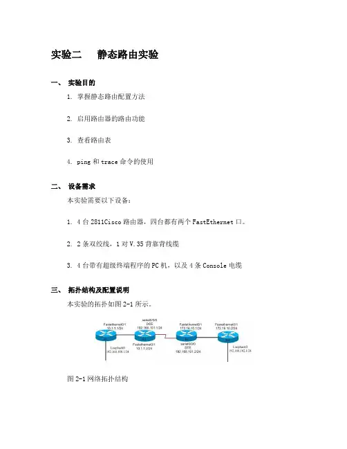
实验二静态路由实验一、实验目的1. 掌握静态路由配置方法2. 启用路由器的路由功能3. 查看路由表4. ping和trace命令的使用二、设备需求本实验需要以下设备:1. 4台2811Cisco路由器,四台都有两个FastEthernet口。
2. 2条双绞线,1对V.35背靠背线缆3. 4台带有超级终端程序的PC机,以及4条Console电缆三、拓扑结构及配置说明本实验的拓扑如图2-1所示。
图2-1网络拓扑结构4台路由器分别命名为R1、R2、R3和R4。
所使用的ip地址分配如图1-1所示。
图中的“/24”表示子网掩码为24位,即255.255.255.0。
实验中,应使用静态路由的设置,实现R1到R4在IP层的连通性,即要求从R1可以ping通R4,反之亦然。
四、实验步骤1. 恢复路由器的初始配置。
(若路由器末被配置过则直接做第三步)2. 给路由器命名router>enable //进入特权模式Router #config terminal //进入配置模式Enter configuration commands, one per line. End with CNTL/Z.Router (config) #Router (config)#hostname r1 //给路由器命名R1 (config)#其它路由器配置类似3. 配置端口IPR1 (config)# interface FastEthernet0/1 //进入FastEthernet0/1端口r1(config-if)#ip address 10.1.1.1 255.255.255.0 //指定端口的IP地址及子网掩码r1(config-if)#no shut //开启端口r1(config-if)#exit //退出端口模式R1 (config)#interface Loopback0 //进入本地回环接口0r1(config-if)#ip address 192.168.100.1 255.255.255.0其它路由器配置类似配完各个路由器的名字及IP后,通过sh run(特权模式下的命令)命令查看路由器的配置把你所看到的结果记录下来。
PT 实验(八) 路由器静态路由配置

PT 实验(八) 路由器静态路由配置一、实验目标●掌握静态路由的配置方法和技巧;●掌握通过静态路由方式实现网络的连通性;●熟悉广域网线缆的连接方式;二、实验背景学校有新旧两个校区,每个校区是一个独立的局域网,为了使新旧校区能够正常相互通讯,共享资源,每个校区出口利用一台路由器进行连接,两台路由器间学校申请了一条2M的DDN专线进行相连,要求你做适当配置实现两个校区间的正常相互访问。
三、技术原理路由器属于网络层设备,能够根据IP包头的信息,选择一条最佳路径将数据包转发出去,实现不同网段的主机之间的互相访问。
路由器是根据路由表进行选路和转发的,而路由表就是由一条条路由信息组成。
生成路由表主要有两种方法:手工配置和动态配置,即静态路由协议配置和动态路由协议配置。
静态路由是指由网络管理员手工配置的路由信息。
静态路由除了具有简单、高效、可靠的优点外,它的另一个好处是网络安全保密性高。
缺省路由可以看作是静态路由的一种特殊情况。
当数据在查找路由表时,没有找到和目标相匹配的路由表项时,为数据指定的路由。
四、实验步骤实验拓扑1、在路由器R1、R2上配置接口的IP地址和R1串口上的时钟频率;2、查看路由器生成的直连路由;3、在路由器R1、R2上配置静态路由;4、验证R1、R2上的静态路由配置;5、将PC1、PC2主机默认网关分别设置为与路由器接口f1/0 IP地址;6、PC1、PC2主机之间可以互相通信;R1:Router>enRouter#conf tEnter configuration commands, one per line. End with CNTL/Z.Router(config)#hostname R1R1(config)#interface fa1/0R1(config-if)#ip address 192.168.1.1 255.255.255.0R1(config-if)#no shutdown%LINK-5-CHANGED: Interface FastEthernet1/0, changed state to up%LINEPROTO-5-UPDOWN: Line protocol on Interface FastEthernet1/0, changed state to up R1(config-if)#exitR1#show ip routeCodes: C - connected, S - static, I - IGRP, R - RIP, M - mobile, B - BGPD - EIGRP, EX - EIGRP external, O - OSPF, IA - OSPF inter areaN1 - OSPF NSSA external type 1, N2 - OSPF NSSA external type 2E1 - OSPF external type 1, E2 - OSPF external type 2, E - EGPi - IS-IS, L1 - IS-IS level-1, L2 - IS-IS level-2, ia - IS-IS inter area* - candidate default, U - per-user static route, o - ODRP - periodic downloaded static routeGateway of last resort is not setC 192.168.1.0/24 is directly connected, FastEthernet1/0R1#R1(config)#interface serial 0/0R1(config-if)#ip address 192.168.5.2 255.255.255.0R1(config-if)#no shutdown%LINK-5-CHANGED: Interface Serial0/0, changed state to up%SYS-5-CONFIG_I: Configured from console by console%LINEPROTO-5-UPDOWN: Line protocol on Interface Serial0/0, changed state to upR1(config-if)#clock rate 64000R1(config-if)#endR1#show ip routeCodes: C - connected, S - static, I - IGRP, R - RIP, M - mobile, B - BGPD - EIGRP, EX - EIGRP external, O - OSPF, IA - OSPF inter areaN1 - OSPF NSSA external type 1, N2 - OSPF NSSA external type 2E1 - OSPF external type 1, E2 - OSPF external type 2, E - EGPi - IS-IS, L1 - IS-IS level-1, L2 - IS-IS level-2, ia - IS-IS inter area* - candidate default, U - per-user static route, o - ODRP - periodic downloaded static routeGateway of last resort is not setC 192.168.1.0/24 is directly connected, FastEthernet1/0C 192.168.5.0/24 is directly connected, Serial0/0R1#conf tEnter configuration commands, one per line. End with CNTL/Z.R1(config)#ip route 192.168.2.0 255.255.255.0 192.168.5.3R1(config)#endR1#%SYS-5-CONFIG_I: Configured from console by consoleR1#show ip routeCodes: C - connected, S - static, I - IGRP, R - RIP, M - mobile, B - BGPD - EIGRP, EX - EIGRP external, O - OSPF, IA - OSPF inter areaN1 - OSPF NSSA external type 1, N2 - OSPF NSSA external type 2E1 - OSPF external type 1, E2 - OSPF external type 2, E - EGPi - IS-IS, L1 - IS-IS level-1, L2 - IS-IS level-2, ia - IS-IS inter area* - candidate default, U - per-user static route, o - ODRP - periodic downloaded static routeGateway of last resort is not setC 192.168.1.0/24 is directly connected, FastEthernet1/0S 192.168.2.0/24 [1/0] via 192.168.5.3C 192.168.5.0/24 is directly connected, Serial0/0R1#R2:Router>enRouter#conf tEnter configuration commands, one per line. End with CNTL/Z.Router(config)#hostname R2R2(config)#interface fa1/0R2(config-if)#ip address 192.168.2.1 255.255.255.0R2(config-if)#no shutdown%LINK-5-CHANGED: Interface FastEthernet1/0, changed state to up%LINEPROTO-5-UPDOWN: Line protocol on Interface FastEthernet1/0, changed state to up R2(config-if)#exitR2(config)#interface serial 0/0R2(config-if)#ip address 192.168.5.3 255.255.255.0R2(config-if)#no shutdown%LINK-5-CHANGED: Interface Serial0/0, changed state to up%SYS-5-CONFIG_I: Configured from console by console%LINEPROTO-5-UPDOWN: Line protocol on Interface Serial0/0, changed state to upR2(config-if)#endR2#R2#show ip routeCodes: C - connected, S - static, I - IGRP, R - RIP, M - mobile, B - BGPD - EIGRP, EX - EIGRP external, O - OSPF, IA - OSPF inter areaN1 - OSPF NSSA external type 1, N2 - OSPF NSSA external type 2E1 - OSPF external type 1, E2 - OSPF external type 2, E - EGPi - IS-IS, L1 - IS-IS level-1, L2 - IS-IS level-2, ia - IS-IS inter area* - candidate default, U - per-user static route, o - ODRP - periodic downloaded static routeGateway of last resort is not setC 192.168.2.0/24 is directly connected, FastEthernet1/0C 192.168.5.0/24 is directly connected, Serial0/0R2#conf tEnter configuration commands, one per line. End with CNTL/Z.R2(config)#ip route 192.168.1.0 255.255.255.0 192.168.5.2R2(config)#end%SYS-5-CONFIG_I: Configured from console by consoleR2#show ip routeCodes: C - connected, S - static, I - IGRP, R - RIP, M - mobile, B - BGPD - EIGRP, EX - EIGRP external, O - OSPF, IA - OSPF inter areaN1 - OSPF NSSA external type 1, N2 - OSPF NSSA external type 2E1 - OSPF external type 1, E2 - OSPF external type 2, E - EGPi - IS-IS, L1 - IS-IS level-1, L2 - IS-IS level-2, ia - IS-IS inter area* - candidate default, U - per-user static route, o - ODRP - periodic downloaded static routeGateway of last resort is not setS 192.168.1.0/24 [1/0] via 192.168.5.2C 192.168.2.0/24 is directly connected, FastEthernet1/0C 192.168.5.0/24 is directly connected, Serial0/0R2#五、测试Packet Tracer PC Command Line 1.0PC>ipconfigIP Address......................: 192.168.1.2Subnet Mask.....................: 255.255.255.0Default Gateway.................: 192.168.1.1PC>ping 192.168.2.2Pinging 192.168.2.2 with 32 bytes of data:Request timed out.Reply from 192.168.2.2: bytes=32 time=17ms TTL=126Reply from 192.168.2.2: bytes=32 time=21ms TTL=126Reply from 192.168.2.2: bytes=32 time=16ms TTL=126Ping statistics for 192.168.2.2:Packets: Sent = 4, Received = 3, Lost = 1 (25% loss), Approximate round trip times in milli-seconds:Minimum = 16ms, Maximum = 21ms, Average = 18msPC>。
静态路由实验报告

静态浮动路由一、实验目的(蓝色字体为参考格式, 具体内容结合实验编写)1.掌握静态路由的原理及配置;2.掌握静态缺省路由的原理及配置;3.掌握静态浮动路由的原理及配置;二、实验要求举例说明: 该部分可以是实习项目的实际需求(根据实习的实际内容自己填写)某公司网络如图所示:其中pc2是内网电脑, 要求在pc2上能ping通pc1(服务器8.8.8.8);在公司的边界路由器上为了可靠性使用了双线做备份, 但是查看RT2路由表正常情况下只能看到202.112.1.1为下一跳的路由, 当202.112.1.1网段的线缆断了才会出现202.113.1.1为下一跳的路由, 在RT1上也是同理;只能看到112的路由, 当112链路断掉才会出现113链路为下一跳的路由;三、实验内容及步骤1 网络拓扑(例如下图所示)2 方法和步骤2.1 : 配置IP地址:RT1:<RT1>system-viewSystem View: return to User View with Ctrl+Z.[RT1]int g0/0/1[RT1-GigabitEthernet0/0/1]ip add 12.1.1.1 255.255.255.0[RT1-GigabitEthernet0/0/1]int g0/0/2[RT1-GigabitEthernet0/0/2]ip add 10.1.1.1 255.255.255.0[RT1-GigabitEthernet0/0/2]int lo0[RT1-LoopBack0]ip add 1.1.1.1 255.255.255.255RT2:<RT2>system-viewSystem View: return to User View with Ctrl+Z.[RT2]int g0/0/1[RT2-GigabitEthernet0/0/1]ip add 12.1.1.2 255.255.255.0[RT2-GigabitEthernet0/0/1]int g0/0/2[RT2-GigabitEthernet0/0/2]ip add 10.1.1.2 255.255.255.0[RT2-GigabitEthernet0/0/2]int g0/0/0[RT2-GigabitEthernet0/0/0]ip add 23.1.1.2 255.255.255.0RT3:<RT3>sySystem View: return to User View with Ctrl+Z.[RT3]int g0/0/0[RT3-GigabitEthernet0/0/0]ip add 23.1.1.3 255.255.255.0[RT3-GigabitEthernet0/0/0]int lo0[RT3-LoopBack0]ip add 3.3.3.3 255.255.255.2552.2.1 : 配置RT3的静态路由:[RT3]ip route-static 12.1.1.0 255.255.255.0 g0/0/0 23.1.1.2[RT3]ip route-static 1.1.1.1 255.255.255.255 g0/0/0 23.1.1.22.2.2 : 配置RT2的静态路由:[RT2]ip route-static 1.1.1.1 255.255.255.255 g0/0/1 12.1.1.1[RT2]ip route-static 1.1.1.1 255.255.255.255 g0/0/2 10.1.1.1 preference 61[RT2]ip route-static 3.3.3.3 255.255.255.255 g0/0/0 23.1.1.32.2.3 : 配置RT1的静态路由:[RT1]ip route-static 23.1.1.3 255.255.255.0 g0/0/1 12.1.1.2[RT1]ip route-static 23.1.1.3 255.255.255.0 g0/0/2 10.1.1.2 preference 61[RT1]ip route-static 3.3.3.3 255.255.255.255 g0/0/2 10.1.1.2 preference 61[RT1]ip route-static 3.3.3.3 255.255.255.255 g0/0/1 12.1.1.2验证:Pc2能ping通pc1查看路由表RT1:[RT1]dis ip routing-tableRouting Tables: PublicDestinations : 10 Routes : 11Destination/Mask Proto Pre Cost NextHop Interface8.8.8.0/24 Direct 0 0 8.8.8.1 GE0/0/2 8.8.8.1/32 Direct 0 0 127.0.0.1 InLoop0 10.0.12.0/24 Static 20 0 202.112.1.2 GE0/0/0 127.0.0.0/8 Direct 0 0 127.0.0.1 InLoop0 127.0.0.1/32 Direct 0 0 127.0.0.1 InLoop0 192.168.1.0/24 Static 60 0 202.113.1.2 GE0/0/1Static 60 0 202.112.1.2 GE0/0/0 202.112.1.0/24 Direct 0 0 202.112.1.1 GE0/0/0 202.112.1.1/32 Direct 0 0 127.0.0.1 InLoop0 202.113.1.0/24 Direct 0 0 202.113.1.1 GE0/0/1 202.113.1.1/32 Direct 0 0 127.0.0.1 InLoop0RT2:[RT2]dis ip roRouting Tables: PublicDestinations : 10 Routes : 10Destination/Mask Proto Pre Cost NextHop Interface8.8.8.0/24 Static 20 0 202.112.1.1 GE0/0/0 10.0.12.0/24 Direct 0 0 10.0.12.1 GE0/0/1 10.0.12.1/32 Direct 0 0 127.0.0.1 InLoop0 127.0.0.0/8 Direct 0 0 127.0.0.1 InLoop0 127.0.0.1/32 Direct 0 0 127.0.0.1 InLoop0 192.168.1.0/24 Static 60 0 10.0.12.2 GE0/0/1 202.112.1.0/24 Direct 0 0 202.112.1.2 GE0/0/0 202.112.1.2/32 Direct 0 0 127.0.0.1 InLoop0 202.113.1.0/24 Direct 0 0 202.113.1.2 GE0/0/2 202.113.1.2/32 Direct 0 0 127.0.0.1 InLoop0RT3:[RT3]dis ip rodis ip roRouting Tables: PublicDestinations : 9 Routes : 9Destination/Mask Proto Pre Cost NextHop Interface8.8.8.0/24 Static 60 0 10.0.12.1 GE0/0/0 10.0.12.0/24 Direct 0 0 10.0.12.2 GE0/0/0 10.0.12.2/32 Direct 0 0 127.0.0.1 InLoop0 127.0.0.0/8 Direct 0 0 127.0.0.1 InLoop0 127.0.0.1/32 Direct 0 0 127.0.0.1 InLoop0 192.168.1.0/24 Direct 0 0 192.168.1.1 GE0/0/1 192.168.1.1/32 Direct 0 0 127.0.0.1 InLoop0 202.112.1.0/24 Static 60 0 10.0.12.1 GE0/0/0 202.113.1.0/24 Static 60 0 10.0.12.1 GE0/0/0四、实验心得及体会通过这次试验, 掌握了静态路由的原理及配置, 还有静态缺省路由和静态浮动路由的原理及配置, 静态路由适用小型网络。
实验八--静态路由(stu)

实验八静态路由一、实验目的1掌握通过静态路由方式实现网络的连通性二、实验设备和器材三、背景描述假设校园网通过1台路由器连接到校园外的另1台路由器上,现要在路由器上做适当配置,实现校园网内部主机与校园网外部主机的相互通信。
四、实验原理、内容与步骤●路由表的产生方式一般有3种:直连路由、静态路由、动态路由●静态路由:是指由网络管理员在路由器中手工配置的固定路由信息。
是对远方非直连网络的到达方法在路由器上进行明确的路由告知。
路由明确地指定了数据分组到达目的地必须经过的路径。
●一个路由器有几个非直连网络,就要配置几条静态路由。
●静态路由的一般配置步骤●步骤1:网络规划:确定网段个数,为互联网络中的每个网段确定地址(包括子网地址和接口IP,主机IP分配)。
●步骤2:为参与连接的路由器接口配置IP地址、激活接口●步骤3:确定本路由器有哪些直连网段●步骤4:确定网络中有哪些属于本路由器的非直连网段,为每个路由器配置每个非直网段的静态路由。
五、注意事项1、如果两台路由器通过串口直接互连,则必须在其中一端设置时钟频率(DCE)2、静态路由是单向的,两边路由器均要配置路由条目,才能实现数据的往返。
3、要根据网络拓扑结构,找出每一个路由器的非直连网络。
4、静态路由配置的下一跳地址是那个能够到达远方网络的下一站路由器的入口地址,而不是自己的出口地址。
是自己的出口号六、拓扑结构七、实验报告要求1、写出实验步骤与屏幕截图,记录实验中的各种情况。
2、提出对本次实验的意见、建议和心得。
八、参考配置步骤一:网络规划1)三个网段:网络号分别是: , ,路由器名 RouterA,RouterB 快速以太网口F1/0 RA,RB快速以太网口F1/1 终端主机名网卡接口IP 与网关IP RouterAIP : mask : IP : mask : PC1IP : GW :RouterBPC22)确定网络中有哪些属于本路由器的非直连网段: RouterA :非直连网段是:网络号 ,直连网段有: ,RouterB :非直连网段 ,直连网段: ,F1/0F1/0F1/1F1/1步骤二:查看已知路由配置信息1、查看R1,R2路由器配置,与路由器接口的摘要信息(如果是用串口,检查s0/0口DCE端是否已经配置时钟频率)#show run#conf t#show ip interface brief步骤三:配置路由器接口IP:1、在路由器Router1上:●配置f1/0,F1/1接口的ip地址,●开启接口no shutdown●验证:show命令验证路由器接口的配置Red-Giant(config)#hostname Router1Router1(config)#interface fastEthernet 1/0Router1(config-if)#ip address 192.168.1.254 255.255.255.0Router1(config-if)#no shutdownRouter1(config-if)#exitRouter1(config)#interface Fa 1/1Router1(config-if)#ip address 192.168.2.253 255.255.252.0Router1(config-if)#no shutdownRouter2(config-if)#exitRouter1#show ip interface brief //查看接口摘要信息Router1#show interfaces F1/0 !查看端口信息2、在路由器Router2上:操作同路由器13、分别查看两个路由器的路由信息:Router1#show ip route //查看路由信息C 192.168.1.0/24 is directly connected, FastEthernet 0/0C 192.168.2.0/24 is directly connected, FastEthernet 1/1//配置了接口ip,直连路由自动生成4、配置主机1,2网络参数:1)设置IP,子网掩码2)分别在PC1,PC2上手动添加软路由-----默认网关路由:在PC1上添加:Router add 目的网络号(192.168.3.0)目的网络子网掩码(2255.255.255.0)本网络默认网关(192.168.1.254)metric 20在PC2上添加:Router add 目的网络号(192.168.1.0)目的网络子网掩码(2255.255.255.0)本网络默认网关(192.168.3.254)metric 205、逐段验证配置连通性:在PC1:PC1>ping 192.168.1.254 //验证与自己的网关连通性PC1>ping 192.168.2.253 (可否ping通?)验证与本路由器出接口连通性PC1>ping 192.168.2.254(可否ping通?)验证与路由器直连的下一跳路由器入接口连通性在Router1上:R1>ping 192.168.2.253R1>ping 192.168.2.254R1>ping 192.168.1.254R1>ping 192.168.1.1R1>ping 192.168.3.254(可否ping通?)R1>ping 192.168.3.1(可否ping通?)结论:在完成了路由器接口等基本配置工作后,作为项目实施人员的你发现:●对公司中所有的主机而言,只能与位于同一网段的主机或充当主机网关的路由器接口具有IP的连通性;●对路由器来说,则只能与下一跳路由器直连的接口通信,但不能与远端路由器非直连接口或远程网络中的主机进行通信。
路由器试验测试报告_静态路由
系别:
网络工程系专业:
计算机网络技术
班级: 学号: 姓名:
任课教
师:
测试得
分:
实验目
的: 静态路由配置
实验内
容:
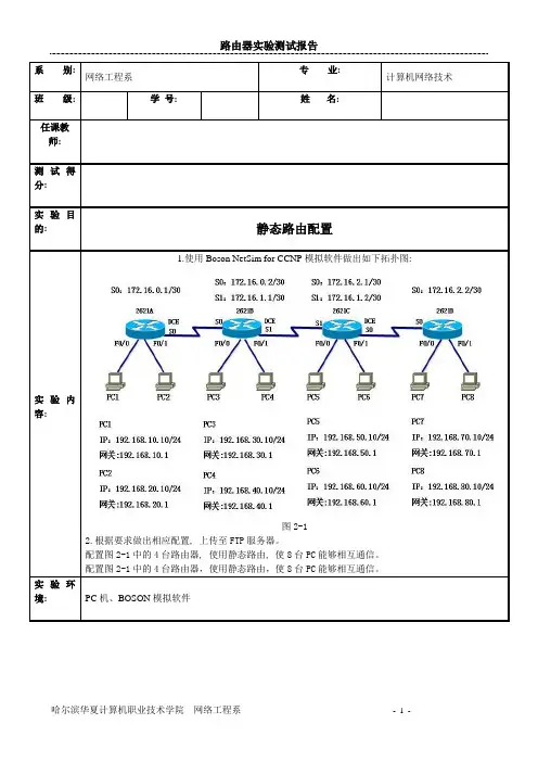
1.使用Boson NetSim for CCNP模拟软件做出如下拓扑图:
图2-1
2.根据要求做出相应配置, 上传至FTP服务器。
配置图2-1中的4台路由器, 使用静态路由, 使8台PC能够相互通信。
配置图2-1中的4台路由器,使用静态路由,使8台PC能够相互通信。
实验环
境: PC机、BOSON模拟软件
1、拷贝配置过程: (要求在相应的配置命令后做中文注解)
2.回答下列问题:
(1)配置静态路由时, 配置下一跳接口IP地址与配置本路由器的接口有什么区别:(2)简述静态路由与动态路由的区别:
(3)简述静态路由的优缺点:
(4)什么是默认路由, 如何配置默认路由, 举例说明:。
静态路由的配置实验报告
静态路由的配置实验报告静态路由的配置实验报告概述:静态路由是网络中常用的一种路由配置方式,它通过手动配置路由表来指定数据包的转发路径。
本实验旨在通过配置静态路由,实现不同网络之间的通信,并对配置过程和结果进行分析。
实验环境:本实验使用了三台虚拟机,分别代表不同的网络。
其中,虚拟机A位于192.168.1.0/24网络,虚拟机B位于192.168.2.0/24网络,虚拟机C位于192.168.3.0/24网络。
虚拟机A作为路由器,连接了虚拟机B和虚拟机C。
实验步骤:1. 配置虚拟机A的网络接口:在虚拟机A中,打开终端,输入命令“sudo ifconfig eth0 192.168.1.1/24”来配置eth0接口的IP地址为192.168.1.1,子网掩码为255.255.255.0。
2. 配置虚拟机B的网络接口:在虚拟机B中,打开终端,输入命令“sudo ifconfig eth0 192.168.2.1/24”来配置eth0接口的IP地址为192.168.2.1,子网掩码为255.255.255.0。
3. 配置虚拟机C的网络接口:在虚拟机C中,打开终端,输入命令“sudo ifconfig eth0 192.168.3.1/24”来配置eth0接口的IP地址为192.168.3.1,子网掩码为255.255.255.0。
4. 配置虚拟机A的静态路由:在虚拟机A中,打开终端,输入命令“sudo route add -net 192.168.2.0netmask 255.255.255.0 gw 192.168.1.1”来添加到达192.168.2.0/24网络的静态路由,下一跳为192.168.1.1。
同样地,输入命令“sudo route add -net 192.168.3.0 netmask 255.255.255.0gw 192.168.1.1”来添加到达192.168.3.0/24网络的静态路由。
eNSP静态路由配置实验报告
eNSP静态路由配置实验报告eNSP静态路由配置实验姓名:X学号:X班级:X课程名称:静态路由配置实验提交日期:年月日注:仅供参考一、实验名称:静态路由配置二、实验目的:实了解静态路由的原理,掌握静态路由的配置方法三、实验软件:eNSP四、实验任务:1.配置基本静态路由2.配置默认静态路由3.实现静态路由的负载分担4.实现静态路由的路由备份五、实验步骤1.基本静态路由配置⑴构建实验拓扑图,配置主机参数,并启动设备Pc1-IP:10.1.1.2 Gateway:30Pc2-IP:20.1.1.2 Gateway:30R1-GE0/0/0-IP:10.1.1.1 Gateway:24 R1-GE0/0/1-IP:1.1.1.1 Gateway:24 R2-GE0/0/1-IP:1.1.1.2 Gateway:24 R2-GE0/0/0-IP:20.1.1.1 Gateway:30 ⑵静态路由配置R1:<Huawei>system-view[Huawei]interface GigabitEthernet0/0/0[Huawei-GigabitEthernet0/0/0]ip address 10.1.1.1 30[Huawei-GigabitEthernet0/0/0]quit[Huawei]interface GigabitEthernet0/0/1[Huawei-GigabitEthernet0/0/1]ip address 1.1.1.1 24[Huawei-GigabitEthernet0/0/1]quit[Huawei]ip route-static 20.1.1.0 30 1.1.1.2(注:添加静态路由信息)R2:<Huawei>system-view[Huawei]interface GigabitEthernet0/0/1[Huawei-GigabitEthernet0/0/1]ip address 1.1.1.2 24[Huawei-GigabitEthernet0/0/1]quit[Huawei]interface GigabitEthernet0/0/0[Huawei-GigabitEthernet0/0/0]ip address 20.1.1.1 30[Huawei-GigabitEthernet0/0/0]quit[Huawei]ip route-static 10.1.1.0 30 1.1.1.1⑶查看信息①查看接口与IP相关的配置和统计信息或者简要信息配置静态路由前配置静态路由后②查看路由表配置静态路由前配置静态路由前后⑷检测主机间的连接性Pc1 ping Pc2如上可知,通过配置静态路由,可实现不同网段间的联通。
静态路由配置实验报告
实验七静态路由配置1、项目目的掌握在器上配置静态路由。
2、项目描述某公司网络通过一台路由器连接到网络服务提供商ISP的路由器上,现在要在路由器做适当的配置,实现企业内部主机与互联网主机之间的相互通信。
本项目以三台2811路由器为例,路由器分别命名为:RouterA、RouterB 和RouterC,路由器之间通过串口采用V35 DCE/DTE电缆连接,DCE端连接RouterA上。
PC0的IP地址和默认网关分别为:192.168.1.2和192.168.1.1,PC2的IP地址和默认网关分别为:192.168.2.2和192.168.2.1,子网掩码都是255.255.255.0。
RouterA与RouterB之间使用10.1.1.0/30网段,RouterB与RouterC之间使用10.1.1.4/30网段。
3、实现功能实现网络的互联互通,从而实现信息的共享和传递。
4、项目拓扑2811路由器(3台)、V35DCE电缆(1根)、V35DTE电缆(1根)、RJ45交叉线(2根)。
5、项目步骤(1)在路由器RouterA上配置接口的IP地址和串口上的时钟频率。
RouterA(config)#interface fastethernet 0/0 //进入接口F0/0的配置模式。
RouterA(config-if)#ip address 192.168.1.1 255.255.255.0 //配置路由器接口F0/0的IP地址。
RouterA(config-if)#no shutdown //开启路由F0/0接口。
RouterA(config)#interface serial0/0/0 //进入接口S0/0/0的配置模式。
RouterA(config-if)#ip address 10.1.1.1 255.255.255.252 //配置路由器接口S0/0/0的IP地址。
RouterA(config-if)#clock rate 64000 //配置DCE 时钟频率。
《计算机网络》实验六 静态路由配置 实验报告
实验报告六班级:07东方信息姓名:学号:实验时间:10年5月17日机房:9#205 组号:机号:A一、实验题目静态路由配置二、实验设备CISCO路由器、专用电缆、网线、CONSOLE线、PC机三、实验内容1了解路由器的功能2在CISCO路由器上设置和验证静态路由3配置缺省路由四、原理实现网络的互连互通,从而实现信息的共享和传输。
静态路由实验网络拓扑结构图:五、实际步骤步骤1:初始化设置(1)按照图4-1的网络拓扑结构,连接好PC与路由器的网线、PC与路由器Console端口的调试电缆、路由器与路由器之间的V.35电缆。
(2)按照图4-1要求,在PC1、PC2计算机中设置好IP地址、子网掩码、默认网关。
然后利用Ping命令测试两台PC机之间的连通性。
模拟器也按以上配置。
(3)在PC机上启动“超级终端”。
步骤2:路由器 Route A 的基础配置7-A#show runBuilding configuration...Current configuration : 826 bytes!version 12.3service timestamps debug datetime msecservice timestamps log datetime msecno service password-encryption!hostname 7-A!boot-start-markerboot-end-marker!enable password cisco!no network-clock-participate aim 0no network-clock-participate aim 1no aaa new-modelip subnet-zero!!ip cef!!no ftp-server write-enable!!!!interface FastEthernet0/0ip address 10.7.3.1 255.255.255.0duplex autospeed auto!interface FastEthernet0/1ip address 10.7.1.1 255.255.255.0 duplex autospeed auto!interface Serial0/3/0ip address 172.17.200.5 255.255.255.252 no fair-queue!interface Serial0/3/1no ip addressshutdownclockrate 2000000!ip classlessip http server!!!control-plane!!line con 0line aux 0line vty 0 4password ciscologin!scheduler allocate 20000 1000!End步骤3:路由器Route B 的基础配置7-B#show runBuilding configuration...Current configuration : 868 bytes!version 12.3service timestamps debug datetime msec service timestamps log datetime msecno service password-encryption!hostname 7-B!boot-start-markerboot-end-marker!enable password cisco!no network-clock-participate aim 0no network-clock-participate aim 1no aaa new-modelip subnet-zero!!ip cef!!no ftp-server write-enable!!!!interface FastEthernet0/0ip address 10.7.3.1 255.255.255.0 shutdownduplex autospeed auto!interface FastEthernet0/1ip address 10.7.2.1 255.255.255.0 duplex autospeed auto!interface Serial0/3/0ip address 172.17.200.6 255.255.255.252 no fair-queueclockrate 128000!interface Serial0/3/1bandwidth 64no ip addressshutdownclockrate 2000000!ip classlessip http server!!!control-plane!!line con 0line aux 0line vty 0 4password ciscologin!scheduler allocate 20000 1000!end步骤4:在 Route A 上配置静态路由7-A(config)#ip route 10.7.2.0 255.255.255.0 172.17.200.67-A(config)#10.7.4.0 255.255.255.0 172.17.200.6步骤5:检查9-A上的路由表7-A#show ip routeCodes: C - connected, S - static, R - RIP, M - mobile, B - BGPD - EIGRP, EX - EIGRP external, O - OSPF, IA - OSPF inter areaN1 - OSPF NSSA external type 1, N2 - OSPF NSSA external type 2E1 - OSPF external type 1, E2 - OSPF external type 2i - IS-IS, su - IS-IS summary, L1 - IS-IS level-1, L2 - IS-IS level-2ia - IS-IS inter area, * - candidate default, U - per-user static routeo - ODR, P - periodic downloaded static routeGateway of last resort is not set172.17.0.0/30 is subnetted, 1 subnetsC 172.17.200.4 is directly connected, Serial0/3/010.0.0.0/24 is subnetted, 4 subnetsS 10.7.4.0 [1/0] via 172.17.200.6C 10.7.1.0 is directly connected, FastEthernet0/1C 10.7.3.0 is directly connected, FastEthernet0/0S 10.7.2.0 [1/0] via 172.17.200.6步骤6:Ping 7-B的FastEthernet端口的地址。