QS8005使用手册完整
朗林式式 模式 8005 智能门系统快速启动指南说明书

7”7”40.5” Fixed Position90°Securely mount a control box near the actuator armwith appropriate hardware (notsupplied).Gate Hinge Pivot Point Coaxial CableAntenna Actuator CableP o w e r C o n d u i tL o o p s C o n d u i tFront Bracket Pivot PointFront BracketRear Bracket(Adjustable, See Manual)Rear Bracket Pivot PointClosed PositionOpen to the Inside PositionControl BoxActuator arm and brackets MUST be level !6003-066-P-6-17LimitSlow DownU ns c re w 4 s cr e ws t or em o v ec o ve r .L o os e n nu tt o ad j u s t l i mi t se n s o r .Note: This illustration shows NO gate hinge inset. If gate hinge is inset on wall, see “Rear Bracket Configurations for Different Gate Hinge Insets” in the 6003 Actuator Arm and Control Box Mounting manual.Circuit board power must be ON to adjust limit sensors, LEDs will light.Cut Off Excess BracketCut Off Excess BracketBottomMiddle TopThe 6003 is intended for installation only on swing gates used for vehicles.Pedestrians must be supplied with a separate access opening. For safety and installation instructions, please refer to 6003 Actuator Arm and Control Box Mounting manual, 115 VAC or Solar Control Box Wiring/Owner’s manuals .3 Li m i t5 L i m it 4 Sl oD w n 6 Sl o D wn 120 S. Glasgow Avenue Inglewood, California 90301U.S.A.THIS PRODUCT IS TO BE INSTALLED AND SERVICED BY A TRAINED GATE SYSTEMS TECHNICIAN ONLY . Visit to find a professional installing and servicing dealer in your area.M anually release the arm and fully extend the powered shaft. Rotate it back two full turns before installing the arm.Unlock operator to manually move gate.Prevent Powered Shaft from Bottoming OutRotate back 2 turns before installing.Manual ReleaseFully Extended (Bottomed Out)Powered ShaftBrown wire Blue wire Orange wire Red wire Yellow wire Green wire Green/Yellow wireNOT USED7-Wire Operator Actuator CableA support bar must be installed the entire length of the gate to support the pickets.Coaxial Cable Antenna Kit P/N 1514-073 (Sold separately)G a t e C l o s e d21”Typical27.5”Max Photo Sensors HeightClose BeamOpen BeamOpen BeamClose BeamReversing EdgePhoto SensorPhoto SensorSensor mounted just below actuator arm cable.G a t e O p e n e dCopyright 2017 DoorKing, Inc. All rights reserved.External Entrapment Protection DevicesOutside PropertyInside PropertyDO NOT cycle operator before limit sensors andDIP-switches have been adjusted, damage could occur to gate and operator.Single operator connects to PRIMARY connection ONLY on the 115 VAC OR Solar control box circuit board.17865432PRIMARY4302430243025” or lessOpening Direction DIP-Switch 1 (SW 1)Refer to YOUR chosen 115 VAC OR Solar powered control box manuals for complete DIP-switch settings.Manually move the gate to the desired open or closed position. Loosen the limit nuts and slowly slide the limit assemblies until the LIMIT LEDs on the circuit board light up.Rear Bracket ConfigurationsWall2”21/2”3”Straight51/2”Reversing Edge is mounted along ENTIRE end of gate.Potential Entrapment AreaFactory wired jumpers MUST be removed.Operator Opens to the InsideOperator Opens to the InsideNote: Only 1 monitored Device can be connected for each cycling direction. An OPTIONAL Expansion Kit (sold separately) will allow connection for additional devices.Refer to YOUR chosen 115 VAC OR Solar powered control box manuals to wire entrapment protection devices.Open to the InsideOpen to the Outside - Refer to 6003 manualNote: Refer to 6003 manual for “Open to the Outside” installation.The operator MUST OPEN GATE upon initial power up and OPEN command.If the operator closes gate after giving open command, shut off power and reverse this switch setting otherwise operator will NOT function correctly.。
雨鸟8005喷头说明书
gpm in/h
in/h
3.8
0.48
0.56
5.6
0.53
0.62
6.6
0.53
0.61
9.3
0.64
0.74
11.1 0.66
0.76
12.6 0.70
0.81
14.3 0.74
0.85
16.1 0.78
0.90
18.6 0.85
0.98
20.7 0.94
1.09
22.3 1.08
1.25
24.3 1.11
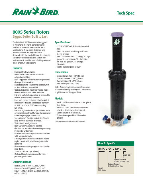
reduce inventory requirements. • Easy, wet, dry arc adjustment with slotted
screwdriver through top of rotor from 50° to 330° part-circle, 360° non-reversing full-circle. • Left and right side trips adjustable for ease of installation without turning the case and loosening the pipe connection. • Seal-A-Matic™ (SAM) check device/riser to help prevent low head drainage. • Water-lubricated gear drive. • Rain Curtain™ nozzles for optimal distribution and close-in watering resulting in superior uniformity. • Nozzles are interchangeable from the front with no special tools. • Self-adjusting turbine stator allows nozzle replacement with no other adjustments required. • Heavy duty retract spring ensures positive pop-down. • Standard rubber cap. (Green) • Optional Purple rubber cover for nonpotable applications
QS8005型流程式尿沉渣分析仪管理使用经验

QS8005型流程式尿沉渣分析仪管理使用经验苏冰;郭瑞林;杨红霞【期刊名称】《实验与检验医学》【年(卷),期】2009(027)004【摘要】QS8005型流式尿沉渣分析仪是南京千盛医疗设备制造有限公司生产的仿手工法尿沉渣自动分析仪器.符合2002年中华医学会检验分会“血液和体液学专家委员会”通过的《尿沉渣检查标准化建议》的相关规定,采用自动控制尿液浓缩、智能扫描识别尿沉渣形态、计算机图像识别软件等一系列新技术,能快速准确地给出分析结果.提供定量分析结果,使医院检验人员从传统繁重手工尿常规检查的劳动中彻底解放出来,实现了检验部门在尿液分析的全自动化.产品由程控组合式离心系统、抽吸尿上清、沉渣机械手、显微镜检盘、尿沉渣图像自动摄像及识别处理系统组成.各系统装置由可编程控制器(PLC)为主的电气系统控制,【总页数】2页(P414,422)【作者】苏冰;郭瑞林;杨红霞【作者单位】陕西中医学院第二附属医院检验科,陕西,咸阳,712000;陕西中医学院第二附属医院检验科,陕西,咸阳,712000;陕西中医学院第二附属医院检验科,陕西,咸阳,712000【正文语种】中文【中图分类】R446.12+1;R169.39【相关文献】1.“森创”步进及交流伺服系统在流程式尿沉渣分析仪上的应用 [J], ;2.尿沉渣分析仪、尿液干化学分析仪测定及尿沉渣镜检红细胞对比分析 [J], 白士丽;刘长青;王晓丽;郎国华3.QS8005流程式尿沉渣分析仪与尿镜检尿RBC、WBC结果分析 [J], 毛鸿华4.尿干化学分析仪、尿沉渣分析仪及尿沉渣镜检结果对比观察 [J], 张慧丽5.尿干化学分析仪、尿沉渣分析仪和尿沉渣镜检联合应用在尿液红细胞检测中的意义 [J], 康星星;刘娟因版权原因,仅展示原文概要,查看原文内容请购买。
海克顿198557生产商品说明书

Eaton 198557Eaton Moeller® series Rapid Link - Speed controller, 4.3 A, 1.5 kW, Sensor input 4, AS-Interface®, S-7.4 for 31 modules, HAN Q5, with braking resistanceGeneral specificationsEaton Moeller® series Rapid Link Speed controller1985574015081964321157 mm 270 mm 220 mm 3.42 kg RoHS UL approval IEC/EN 61800-5-1 CE UL 61800-5-1Product NameCatalog NumberEANProduct Length/Depth Product Height Product Width Product Weight Certifications Catalog Notes can be switched over from U/f to (vector) speed control Connection of supply voltage via adapter cable on round or flexible busbar junction Diagnostics and reset on device and via AS-Interface Four fixed speeds integrated PTC thermistorParameterization: drivesConnect mobile (App) Parameterization: drivesConnectDiagnostics and reset on device and via AS-Interface Parameterization: FieldbusParameterization: KeypadSelector switch (Positions: REV - OFF - FWD)Key switch position HANDPC connectionPTC thermistor monitoringInternal DC linkIGBT inverterFour fixed speedsControl unitBreaking resistanceKey switch position AUTOTwo sensor inputs through M12 sockets (max. 150 mA) for quick stop and interlocked manual operationThermo-click with safe isolationKey switch position OFF/RESETBraking resistance4-quadrant operation possibleBrake chopper with braking resistance for dynamic braking IP65NEMA 121st and 2nd environments (according to EN 61800-3)IIISpeed controllerASIAS-Interface profile cable: S-7.4 for 31 modulesC1: for conducted emissions onlyC2, C3: depending on the motor cable length, the connected load, and ambient conditions. External radio interference suppression filters (optional) may be necessary.2000 VCenter-point earthed star network (TN-S network)AC voltagePhase-earthed AC supply systems are not permitted.Vertical15 g, Mechanical, According to IEC/EN 60068-2-27, 11 ms, Half-sinusoidal shock 11 ms, 1000 shocks per shaftResistance: 57 Hz, Amplitude transition frequency on accelerationResistance: 6 Hz, Amplitude 0.15 mmResistance: 10 - 150 Hz, Oscillation frequencyResistance: According to IEC/EN 60068-2-6Above 1000 m with 1 % performance reduction per 100 m Max. 2000 m-10 °C40 °C-40 °C70 °CFeatures Fitted with:Functions Degree of protectionElectromagnetic compatibility Overvoltage categoryProduct categoryProtocolRadio interference classRated impulse withstand voltage (Uimp) System configuration typeMounting position Shock resistance Vibration AltitudeAmbient operating temperature - min Ambient operating temperature - max Ambient storage temperature - min Ambient storage temperature - maxIn accordance with IEC/EN 50178 < 95 %, no condensation0.4 - 4.3 A, motor, main circuit Adjustable, motor, main circuit < 10 ms, Off-delay < 10 ms, On-delay 98 % (η)4.1 A3.5 mA120 %Maximum of one time every 60 seconds 380 V480 V380 - 480 V (-10 %/+10 %, at 50/60 Hz)Sensorless vector control (SLV) U/f control BLDC motorsSynchronous reluctance motors PM and LSPM motors 0 Hz500 HzFor 60 s every 600 s At 40 °C6.5 AClimatic proofingCurrent limitationDelay timeEfficiency Input current ILN at 150% overload Leakage current at ground IPE - max Mains current distortion Mains switch-on frequencyMains voltage - min Mains voltage - max Mains voltage toleranceOperating modeOutput frequency - min Output frequency - max Overload current Overload current IL at 150% overload45 Hz66 Hz1.5 kW400 V AC, 3-phase480 V AC, 3-phase0.1 Hz (Frequency resolution, setpoint value)200 %, IH, max. starting current (High Overload), For 2 seconds every 20 seconds, Power section50/60 Hz8 kHz, 4 - 32 kHz adjustable, fPWM, Power section, Main circuitCenter-point earthed star network (TN-S network)AC voltagePhase-earthed AC supply systems are not permitted.2 HP≤ 0.6 A (max. 6 A for 120 ms), Actuator for external motor brakeAdjustable to 100 % (I/Ie), DC - Main circuit765 VDC10 kAType 1 coordination via the power bus' feeder unit, Main circuit 24 V DC (-15 %/+20 %, external via AS-Interface® plug)AS-InterfacePlug type: HAN Q5Max. total power consumption from AS-Interface® power supply unit (30 V): 190 mANumber of slave addresses: 31 (AS-Interface®) Specification: S-7.4 (AS-Interface®)C1 ≤ 1 m, maximum motor cable length C2 ≤ 5 m, maximum motor cable length C3 ≤ 25 m, maximum motor cable lengthMeets the product standard's requirements. Meets the product standard's requirements.Rated frequency - minRated frequency - maxRated operational power at 380/400 V, 50 Hz, 3-phase Rated operational voltageResolutionStarting current - maxSupply frequencySwitching frequencySystem configuration type Assigned motor power at 460/480 V, 60 Hz, 3-phase Braking currentBraking torqueSwitch-on threshold for the braking transistorRated conditional short-circuit current (Iq)Short-circuit protection (external output circuits) Rated control voltage (Uc)Communication interfaceConnectionInterfacesCable length10.2.2 Corrosion resistance10.2.3.1 Verification of thermal stability of enclosuresMeets the product standard's requirements.Meets the product standard's requirements.Meets the product standard's requirements.Does not apply, since the entire switchgear needs to be evaluated.Does not apply, since the entire switchgear needs to be evaluated.Meets the product standard's requirements.Does not apply, since the entire switchgear needs to be evaluated.Meets the product standard's requirements.Does not apply, since the entire switchgear needs to be evaluated.Does not apply, since the entire switchgear needs to be evaluated.Is the panel builder's responsibility.Is the panel builder's responsibility.Is the panel builder's responsibility.Is the panel builder's responsibility.Is the panel builder's responsibility.The panel builder is responsible for the temperature rise Rapid Link 5 - brochureDA-SW-drivesConnect - InstallationshilfeDA-SW-drivesConnect - installation helpDA-SW-USB Driver PC Cable DX-CBL-PC-1M5DA-SW-Driver DX-CBL-PC-3M0DA-SW-USB Driver DX-COM-STICK3-KITDA-SW-drivesConnectMaterial handling applications - airports, warehouses and intra-logisticseaton-bus-adapter-rapidlink-speed-controller-dimensions-003.eps eaton-bus-adapter-rapidlink-speed-controller-dimensions-002.eps eaton-bus-adapter-rapidlink-speed-controller-dimensions-004.eps eaton-bus-adapter-rapidlink-speed-controller-dimensions.epsETN.RASP5-4400A31-5120100S1.edzIL034085ZUramo5_v19.dwgrasp5_v19.stpConfiguration to Rockwell PLC for Rapid LinkGeneration Change RA-SP to RASP5Generation change from RA-SP to RASP 4.0Generation change RAMO4 to RAMO5Generation change from RA-MO to RAMO 4.0Generation Change RASP4 to RASP5DA-DC-00004184.pdfDA-DC-00004514.pdfDA-DC-00003964.pdfDA-DC-00004508.pdf10.2.3.2 Verification of resistance of insulating materials to normal heat10.2.3.3 Resist. of insul. mat. to abnormal heat/fire by internal elect. effects10.2.4 Resistance to ultra-violet (UV) radiation10.2.5 Lifting10.2.6 Mechanical impact10.2.7 Inscriptions10.3 Degree of protection of assemblies10.4 Clearances and creepage distances10.5 Protection against electric shock10.6 Incorporation of switching devices and components10.7 Internal electrical circuits and connections10.8 Connections for external conductors10.9.2 Power-frequency electric strength10.9.3 Impulse withstand voltage10.9.4 Testing of enclosures made of insulating material10.10 Temperature rise BrochureDisegnieCAD modelIstruzioni di installazione mCAD modelNote per l'applicazione Report di certificazioneEaton Corporation plc Eaton House30 Pembroke Road Dublin 4, Ireland © 2023 Eaton. Tutti i diritti riservati. Eaton is a registered trademark.All other trademarks areproperty of their respectiveowners./socialmediacalculation. Eaton will provide heat dissipation data for the devices.Is the panel builder's responsibility. The specifications for the switchgear must be observed.Is the panel builder's responsibility. The specifications for the switchgear must be observed.The device meets the requirements, provided the information in the instruction leaflet (IL) is observed.10.11 Short-circuit rating10.12 Electromagnetic compatibility10.13 Mechanical function。
QS8005流程式尿沉渣分析仪与尿镜检尿RBC\WBC结果分析

QS8005流程式尿沉渣分析仪与尿镜检尿RBC\WBC结果分析目的探讨尿液常规检测中尿沉渣分析仪和尿镜检法的作用。
方法用QS8005流程式尿沉渣分析仪对500例临床病人的尿液进行RBC、WBC2个指标进行检测,并与人工镜检法进行比较,将测定数据进行统计分析。
结果红细胞检测阳性符合率为66.2%,阴性符合率为65.9%;白细胞检测阳性符合率为47.5%,阴性符合率为82.6%。
结论显微镜检查检测速度缓慢,耗时较长,尿液分析仪扩大了尿液检测范围,提高了尿液检查的临床价值,但是会受到许多因素的影响,因此,必须两者结合检查,以提高尿液分析的检测质量。
标签:尿液检测尿液分析仪显微镜尿液检测是一项快捷、方便的三大常规检验项目之一,可为临床疾病诊断提供依据。
特别是红细胞,白细胞两项指标的检测意义较大。
2009年5月~2010年5月,笔者对我院500份送检尿液采用尿沉渣分析仪检测尿标本中红细胞和白细胞,并与人工镜检结果进行比较,以了解两种方法的符合率和影响因素。
现将研究结果报告如下。
1材料与方法1.1标本收集门诊及住院病人新鲜中段尿液500例(女性特别注意避免阴道分泌物污染),留尿后1h内完成RBC、WBC的检测及尿液沉渣镜检。
1.2仪器与方法:1.2.1QS8005流程式尿沉渣分析仪(南京千盛医疗设备制造有限公司产),试剂组成:QS8005流程式尿沉渣分析仪专用染色液。
取l0mL尿液,倒入刻度离心管,充分混匀,将进样针插入试管,按进样开关,自动吸取尿标本800μ1,定量分析红细胞、白细胞等参数,记录分析数据。
正常值WBC:0~20/1、RBC:0~20/1。
超出此范围视为阳性。
1.2.2人工镜检。
采用日本欧林巴斯CHK型双目显微镜。
严格按全国临床检验操作规程规定方法操作[1],以RBC小于3个/HP、WBC小于5个/HP为参考值。
检测结果大于正常值为阳性,在正常值内为阴性。
1.3统计学分析用SPSS13.0软件进行分析。
主控室消防联动NT8005控制系统操作指南

声光启停 手动/自动 急启/急停主控室消防联动NT8005控制系统操作指南一、控制器简介:JB-QB-NT8005火灾报警控制器集报警、消防联动于一体的分布式智能型控制器,采用无极性两总线、2片CPU 同步处理、CAN 总线 通讯、智能算法,具有全数字量、单回路容量大、报警点和联动点任意混接等优点,完全满足风电场消防工作的需要。
二、【火警指示】灯亮时表示有火灾发生。
【启动指示】灯常亮表明系统中有模块正处于启动状态,闪亮表明未收到反馈的信号【反馈指示】表明系统中有设备已启动。
【监管指示】表明系统中有监管信号输入。
【自检指示】表明系统正在进行自检操作。
【故障指示】表明系统中有故障发生。
【屏蔽指示】表明系统中有器件或模块被屏蔽。
备注:红色圈内。
【延时指示】表明系统中有模块正处于延时启动状态。
【模块请启】表明系统发出请求启动信号,有模块正处于等待启动状态。
【主电工作】表明主电工作正常,系统目前正由主电供电。
【备电工作】灯亮时表明目前正由备电供电。
【系统故障】表明程序不能正常运行。
【声光故障】表明系统中有火灾声光警报器故障。
【声光屏蔽】表明系统中有火灾声光警报器被屏蔽。
【传输发送】、【传输接收】、【传输故障】无用。
备注:黄色圈内。
按钮 按钮【声光启动】表明系统中有火灾声或光警报器启动。
【手动/自动】这是一个状态转换键,用来设定系统当前的联动状态。
系统启动后默【声光停止】表明系统中有火灾声或光警报器被启动后停止。
认为手动,按下可切换为自动。
按钮【急启键】当模块处在延时启动或请求启动状态下,按下【急启键】立即启动。
【急停键】当火警页面当模块处在延时启动或启动状态时,按下【急停键】将取消此模块的启动命令,模块恢复正常状态。
【消音键】当有警情发生时,控制器上的扬声器会发出相应的声音,可以按下【消音键】取消报警声音;如果有新的警情,扬声器会重新发出报警声音。
另外,消音键只能消除本控制器扬声器的报警声音,显示盘等设备的报警声音,应使用“操作”的“关闭音响”菜单项。
Radiodetection RD5100 Series 精密水业管道和电缆定位器组合套装说明书

RD5100 SeriesPrecision water industry pipe and cable locator kitsProvided by: (800)404-ATECAdvanced Test Equipment Rentals®RD5100 range overviewThree products specifically addressing the concerns and challenges of users in the Water Industry locating buried pipes and cables.RD5100H2OA precision locator/transmitter pair offering 83kHzGuidance mode and Power mode with depth.83kHz is very well suited to disjointed pipesand cables, and plastic pipes with tracer wire.The signal can be applied either by direct connectionor by induction, which is also an excellent way of lightingup all nearby conductors for blind locates.RD5100SA precision locator of 3 different sonde frequencies for tracingall types of non-metallic pipe. Upgrade with up to 4 active linelocating frequencies later as your needs develop.RD5100H2O+A precision locating kit offering a suite of active, passive andsonde frequencies specifically targeting the needs of Water Industry users. Guidance mode helps you trace your target with user-friendly visual and audio guides, while iLOC™ allows you to control the transmitter remotely using the locator.iLOCSave time on site by controlling your transmitter from distances of up to 1400 feet / 450 meters.Built for on-site use – IP65 Shock resistant, ingress protected casing protects against knocks, drops, water and dust.34iLOC™RD5100H 2O + locatorGuidance mode – TPI turned offLeft/right arrows, plus a Numerical indication from 0 to 999 of the strength of the field from the target, helps you pinpoint its position. Compass, depth and current, when relevant, are also shown in this mode.Locate over longer distances90V signal output and automatic impedance matching 3 YEAR WARRANTYON REGISTRATION AND AGLOBAL SERVICE NETWORK PROVIDE PEACE OF MINDGuidance modeThe length of the arrow tails is proportional to the distance from the target as the RD5100 guides you towards the pipe or cable of interest. The T arget Position Indicator also indicates the direction to the target.CompassSplash-proof keypadLeft / Right arrowsCurrent, in active modeTarget Position IndicatorSignal strength DepthAlkaline battery pack (2 x LR20 D-cells)Headphone connectionBase tray for accessoriesLight weight and ergonomic design for comfortable useRD5100H 2O + T x transmitterHigh contrast screen provides clarity even in bright sunlight5RD5100H 2O locatorRD5100H 2O Tx transm itterRD5100S locator Internal Li-ion batteries and 4 x D-Cell (LR-20) battery compartmentSonde mode:Detects the signal radiated by a compatible sondeHigh visibility reflective design helps protect operators and equipmentInduction mode alignment arrow:Line arrow up with the target pipe or cable to achieve the best couplingMulti use socket:Direct connection outputAccessory outputLi-ion battery charging inputAlkaline battery pack (2 x LR20 D-cells)Li-Ion rechargeable battery pack(standard on RD5100 H 2O)Signal clamping (Optional)Applies a transmitter signal safely to a pipe or live cable up to 125mm /5" diameter without interrupting the supply.InductionA convenient and quick way of applying the transmitter signal to a pipe or cable, where direct connection or signal clamping is not possible.CD (Current Direction) Identify your target amongsta number of parallel utilities.CD arrows confirm you are tracing your target line.7Copyright © 2018 Radiodetection Ltd. All rights reserved. Radiodetection is a subsidiary of SPX Corporation. Radiodetection, RD5100, TruDepth, Strike Alert and iLOC are trademarks of Radiodetection in the United Kingdom and/or other countries. Due to a policy of continued development, we reserve the right to alter or amend any published specification without notice. This document may not be copied, reproduced, transmitted, modified or used, in whole or in part, without the prior written consent of Radiodetection Ltd.90/RD5100/ENG/02Radiodetection is a leading global developer and supplier of test equipment used by utility companies to help install, protect and maintain their infrastructure networks.Visit Global locationsRadiodetection (USA)28 Tower Road, Raymond, Maine 04071, USAToll Free: +1 (877) 247 3797 T el: +1 (207) 655 8525 *******************Pearpoint (USA)39-740 Garand Lane, Unit B, Palm Desert, CA 92211, USAToll Free: +1 800 688 8094 T el: +1 760 343 7350 **************************Radiodetection (Canada)344 Edgeley Boulevard, Unit 34, Concord, Ontario L4K 4B7, CanadaToll Free: +1 (800) 665 7953 T el: +1 (905) 660 9995 *******************Radiodetection Ltd. (UK)Western Drive, Bristol, BS14 0AF, UKTel: +44 (0) 117 976 7776 *******************Radiodetection (France)13 Grande Rue, 76220, Neuf Marché, France Tel: +33 (0) 2 32 89 93 60 *******************Radiodetection (Benelux)Industriestraat 11, 7041 GD ’s-Heerenberg, Netherlands Tel: +31 (0) 314 66 47 00 *******************Radiodetection (Germany)Groendahlscher Weg 118, 46446 Emmerich am Rhein, Germany Tel: +49 (0) 28 51 92 37 20 *******************Radiodetection (Asia-Pacific)Room 708, CC Wu Building, 302-308 Hennessy Road, Wan Chai, Hong Kong SAR, China Tel: +852 2110 8160 ****************************Radiodetection (China)13 Fuqianyi Street, Minghao Building D304, Tianzhu T own, Shunyi District, Beijing 101312, China Tel:+86(0)1081463372 *********************Radiodetection (Australia)Unit H1, 101 Rookwood Road, Yagoona NSW 2199, Australia Tel: +61 (0) 2 9707 3222 *******************。
JB-QB-NT8005控制器说明书

秦皇岛尼特智能科技有限公司
使用说明书
名 称: JB-QB-NT8005 火灾报警控器(联动型) 编号/版次: 2013-11-15
拟 制: 审 核: 标准化: 批 准: 受 控: 分发号:
媒体编号
旧底图总号
底图总号
日期
签名
标记 数量页次/ 更改单号
签名
日期
备注
目录
第一部分 ..................................................................................................................................... - 1
- 1、下载文档前请自行甄别文档内容的完整性,平台不提供额外的编辑、内容补充、找答案等附加服务。
- 2、"仅部分预览"的文档,不可在线预览部分如存在完整性等问题,可反馈申请退款(可完整预览的文档不适用该条件!)。
- 3、如文档侵犯您的权益,请联系客服反馈,我们会尽快为您处理(人工客服工作时间:9:00-18:30)。
仪器定位使用前的检查1.仪器送达目的地卸车后首先目测检查仪器的外观、台面、开关、插座等在运输过程中有无损坏。
2.仪器通电前用万能表测量仪器插座L与N之间的电阻值大约 1.5KΩ,接地线(双色)分别与L、N之间应该“∽”,用万能表测量PLC24V+与公共端之间的阻值应该是750Ω左右。
3.目测检查高分断断路器、光耦等线路有无松动或脱落。
4.用万能表检查医院插座交流220V市电是否正常,三相插座左眼孔应是N,右眼孔应是L,上面中间眼孔应是接地孔(接地孔应与大地有充分联接)。
5.通电后打开侧面总电源开关,注意观察有无异常现象(如:有无电器烧焦的异味、打火等),过几秒钟后打开电脑,然后再打开前面不锈钢六鍵开关的交流220V、直流24V开关。
6.生理盐水储槽加生理盐水、染色剂储槽加染色剂。
7.加载玻片,取尿样杯加水后放到离心盘上。
8.打开界面开始调试仪器。
操作部分一、启动前准备工作1、检查电源线是否连接好;2、检查生理盐水、染色剂是否处在液位的有效位置(大约不低于储糟的1/2、1/3);3、检查罩壳内是否有异物;废物桶、管道的放置是否处在有效位置;4、检查玻片、打印纸是否准备充分;5、检查显微镜粗调位置是否处在图象显示的有效位置,即看一下显微镜的物镜是否低于移动盘的位置,若低的话稍微向上抬一点,以防止镜检盘旋转时碰到物镜。
二、启动1、打开仪器右侧方的总电源开关(警示:是否有异常情况,如焦味。
若有则停止对仪器的使用,检查主控电路。
)2、分别开启电脑,打印机及风扇开关。
3、依次打开220V和24V (220V控制离心盘、摄像头;24V控制机械手1、手2、玻片、镜检盘),打开仪器机盖。
三、样杯放置1、先给尿样杯依次编号,在其对应的化验单上也相应地编号,以防检验顺序错乱,造成检验错误。
把尿液倒入专用的尿样杯中,使其尿量10ml(即在样杯液位标记处)误差保证在±0.2ml。
2、把尿样杯放入离心盘,为保持离心盘的平衡,尿样杯必须对称放置。
系统默认从1号杯位开始做起,若有偶数个样本则对称放置,若有奇数个样本则在相应位置加一个内装水四、操作1、软件的启动与复位(1)启动软件在桌面上双击QS8005图标,即可启动本软件同时进入操作界面,如图(1)(图1)(2)复位系统在操作区中点击“复位”按纽,此时机械手和镜检盘自动复位。
(如图2)(图2)(3)启动系统初始化系统完成后,在操作区中点击“启动”按钮,弹出“离心标本数量输入”对话框,如(图3)。
输入此次检验的样本数量(默认值为12),点击“确定”按钮开始离心,离心进度条显示离心进度,如(图4)。
(离心时间3min,离心转数1540r/min)离心时间和离心速度都符合国家卫生部组织标准规定。
(图3)(图4)(3)当离心结束后,离心盘自动将1号标本定位到吸尿清位置,1号机械手也同时转到吸尿清的位置。
2、吸取尿上清液、滴加染色剂、吹气混匀、吸沉渣、滴加尿样、镜检(1)1号机械手自动向下吸取1号标本的尿上清液,并留下约0.5ml的尿沉渣;(2)1号机械手自动向上复位;(3)离心盘自动旋转使1号标本到达滴染色剂处,手1自动滴一滴染色剂(25ul);(4)离心盘旋转到2号机械手吸沉渣处;(5)2号机械手自动旋转到取尿样处,同时镜检盘也自动加载一片玻片后旋转到滴沉渣处;(6)2号机械手自动向下吹气、混匀1号标本,吸取沉渣、抓取尿样杯;(7)2号机械手自动转到丢杯处将尿杯丢至废物桶中,此过程中离心盘自动转到下一个样本,重复手1的动作;(8)2号机械手旋转至滴沉渣处,自动向玻片池中滴加1号标本的沉渣(20ul);(9)2号机械手自动转至清洗处,自动向下吸取生理盐水以清洗管道内的残余沉渣(为防止交叉感染,每做完一例标本,都要进行清洗);(10)2号机械手自动向上复位;(11)仪器按照以上步骤自动完成12个标本的吸取尿上清液、滴加染色剂、吹气混匀、吸取尿沉渣、自动扔杯、滴加尿样、清洗的过程;(12)当所有的标本取样结束,且标本染色3分钟时间到之后,镜检盘自动旋转到显微镜下面进行调焦、镜检、摄像(此时可将风扇暂时关闭,以防拍图时图像抖动)。
注1:手动调焦情况下:一般先点“快速下调”或“快速上调”进行粗调,使之到达细胞层;再点“上调”或“下调”进行初次微调,再点“上一步”或“下一步”进行再次微调,如果当前视野图像不清晰,可点击“前进”换下一个视野,总共有6个视野可供选择(待到图像调到完全清晰后可点“抓图”,仪器会自动抓取10幅图像并保存);通过物镜和高精度模拟摄像头将细胞的形态、大小、数量清晰地反映到电脑显示屏上,在反映到电脑显示屏的细胞已放大1120倍,在这同时细胞识别软件开始对每个标本所拍的10幅图进行自动分析,并自动打印报告单(系统默认打印所拍10幅图中的第一幅)。
反映到电脑显示屏上的细胞,无需人工识别和点数。
当您对分析结果有疑问时,请再重新打开其标本所拍的10幅图,看分析结果是否正确;注2:“快速上调”和“快速下调”,“上调”和“下调”点一下则一直在工作(此时显微镜处的灯亮),再点一下时则停止工作(此时灯不亮);“上一步”和“下一步”点一下则工作一下,当“快速下调”和“下调”到一定位置时灯不再亮,证明不能再往下调了,此时可以点“快速上调”或“上调”来继续调焦、抓图。
(如图5)(图5)(13)镜检盘自动丢弃已镜检的玻片,并自动按照以上步骤对下一个标本进行镜检摄像,直到完成所有的标本;(14)单独调焦镜检时请将待检样本放到物镜下,点击“单独检查”,即可开始调焦拍图。
(注:如果有几例标本需单独调焦镜检,后面的样本需隔一个位置放置)。
3、基本资料的输入和修改(1)点击界面中的“基本资料输入”按钮,输入病员的基本资料(如图6),输入完毕后点击“添加记录”或是按回车键,资料即可保存并自动转入下一个,即可直接输入病员的基本资料(注:在离心过程中,为节省时间,即可对病员的基本资料进行输入)。
(图6)(2)如需修改某项记录,可先点击“基本资料输入”,找到所要修改的记录,修改完毕后点击“修改记录”即可。
(3)如需修改检验结果,可先点击“数据查询”,找到所要修改的记录,(其中管型和上皮细胞只能显示3种,结晶、细菌、滴虫、精子计数需手动输入)修改完毕后点击“退出”即可。
4、病员尿沉渣分析信息的操作(1)数据显示:界面中的数据栏可显示病员实时数据,并显示当前数据为第几条数据,按“向前一个记录”或“向后一个记录”,可显示当前记录的前一个或是后一个记录。
(2)实时数据查询(可查询当天所做的相关数据):点击菜单栏上的“数据查询”——>“实时数据查询”(或是直接点击界面上的按钮“数据查询”),弹出实时数据查询对话框,选择查询方法(病历号、样本、姓名)并输入关键字,点击“查询”按钮即可,双击查询所得记录可跳出对话框,显示该记录的详细信息。
(3)历史数据查询(可查询当天以前所做的标本):点击“历史数据查询”,弹出历史数据查询对话框,选择查询方法(病历号、姓名)及输入关键字,点击“查询”按钮即可,双击查询所得记录可跳出对话框,显示该记录的详细信息。
(如图7)(图7)(4)病员尿沉渣信息分析报告的打印a)若病员的基本资料输入完成,镜检结果已分析完毕后,且系统设置中已设置为自动打印,电脑则自动打印报告单。
b)如果想对特定某个病员的信息进行打印,查询找到此病员的信息,然后点击“报表单个打印”按钮(系统默认打印第一幅图片);若第一幅图片不清晰,可点击“前一幅图”或“后一幅图”来选择较满意的一幅图片进行打印(并点击“保存”按钮即可)。
5、图片查询(1) 当天所做标本的图片查询点击“我的电脑”——>“本地磁盘(D:)”——>“picture”,可查看当天所做的每个标本的10幅图片;(2) 历史图片查询点击“我的电脑”——>“本地磁盘(D:)”——>“historypicture”,可查看今天以前所做标本的图片(每个标本只有1幅图片,系统默认保存每个标本的第一幅图片),数据库可存50万例。
6、界面“系统设置”中,可设置是否自动打印、自动扔杯,系统自动调焦(如图8)(图8)7、退出(1)点击“退出系统”按钮或是关闭QS8005界面;(2)关闭计算机、打印机;(3)依次关掉24V和220V电源;(4)关掉整机电源。
五、保养1、每天关机前需清洗一次两个机械手(点击界面中“系统控制”——>“机械手1清洗”——>“清洗结束”、“机械手2清洗”——>“清洗结束”)2、关机后及时用酒精棉擦洗仪器表面、吸液(渣)针管、光电开关等;3、生理盐水清洗杯不能用酒精擦洗,可用干酒精棉擦拭;4、每天要倒空废物桶并检查管道的放入;5、每周擦拭一次显微镜、摄像头等。
六、注意事项1、确定供电系统使用的电压稳定,电源线完好无损;2、添加玻片时必须孔位向上;3、离心杯必须平衡放置于离心盘上;4、仪器运行时,严禁将手或其他物体伸入机内,确保机内无异物,离心时禁止打开机盖;5、离心时不能关掉电源,防止发生离心故障,打碎杯子;若离心时突然断电,先关掉220V开关,再关掉24V;若点击离心后,发现220V未打开,应先关掉24V,再依次打开220V、24V;6、启动前必须检查生理盐水、染色剂、玻片、打印纸是否准备充分;废物桶放置是否到位,管道是否处于有效位置;7、使用后的废弃玻片、尿样杯等应及时清理,避免污染;8、电脑必须正常打开和关闭,软件必须正常退出;9、异常情况下必须检查系统状态,必要时重新启动系统;10、关机时,必须先关掉电脑、打印机的电源,随后关掉24V和220V电源,最后再关掉整机电源;11、紧急情况下,操作人员应及时切断电源。
机械部分一、仪器机械部分组成(如图一)QS8005尿沉渣分析仪是由1、台板2、吸尿清机械手3、离心盘机构、4、吸沉渣机械手5、镜检盘6、摄像头7、生理盐水储槽及染色液储槽8、摄像机构9、玻片机构(图一)1.吸尿清机械手(如图二)吸尿清机械手是由步进电机控制,可以左右旋转并上下升降运动。
主要功能:a.从尿样杯中吸取尿清液;b.从染色剂储槽中吸取染色剂并定量加入到尿样杯中;组成结构:直线电机、丝杠支架、吸尿清管、加染色剂悬臂、染色剂光电开关等作用:a.吸取尿上清液,保证沉渣剩余量约为0.5mlb.滴加染色剂( 图二)2.离心盘机构(如图三)QS8005仪器上有一个离心盘,离心盘上带有12个尿样杯套。
(如图三)主要性能:对尿样进行智能编号、高速离心尿中有形成分。
分离后尿沉渣细胞形态完整,定量准确,离心力可控制、噪音小。
组成结构:离心盘、杯套、伺服驱动器、伺服电机等。
作用:自动编号、分离尿有形成分等(图三)3.吸沉渣机械手(如图四)吸沉渣机械手是由步进电机控制,可以左右旋转并上下升降运动主要功能:a.向尿样杯中吹入气体使染色剂与尿沉渣充分混匀;b.从尿样杯中吸取尿沉渣;c.抓取尿样杯并丢入废物桶;d.向载玻片定量滴加尿沉渣;e.吸入生理盐水对滴沉渣管进行冲洗组成结构:直线电机、丝杠支架、吸尿清管、加染色剂悬臂、染色剂光电开关等作用:吹气混匀尿沉渣并吸取足量尿沉渣,并向玻片计数池滴加一滴尿沉渣(图四)4.镜检摄像机构(如图五镜检摄像装置示意图)主要性能:自动加载计数池、定量取样定位;自动调焦显微、高速摄像,图像清晰;自动丢弃一次性计数池并复位。