S7-PDiag使用简介
WAGO与西门子PLC通讯的使用说明(Profibus-DP S7-300)
实验设备:PLC (S7-300 1P 6ES7 315-2FH13-0AB0 Ver2.6)Profibus-DP耦合器750-333 固件版本17IO(DI:750-430 8点;DO:750-530 8点;AI:750-455 4路;AO:750-555 4路)端板:750-600硬件设置:通过750-333上的拨码设置DP节点号。
本次实验DP节点设置为3。
STEP7 V5.5 软件配置1.新建项目(设定项目名称后,点击“OK”)2.创建站对象(右击“项目对象”,选择“Insert New Object”,选择实际使用的PLC类型)3.组态配置(选择上一步添加的PLC,双击“Hardware”,进入组态界面)组态界面如下4.添加设备(选择实际使用设备,注意型号和版本号)首先将导轨拖拽至配置区,如下图按照实际型号添加设备选择实际版本将其拖拽至导轨的绿色框中,如下图PLC添加完成后,如下图添加Profibus-DP网络(双击“导轨”中的“MPI/DP”,在弹出的对话框中,将“Interface”中的“Type”从“MPI”改成“PROFIBUS”)改成“PROFIBUS”后,随即跳出“Properties”对话框。
点击“New”,设置PROFIBUS网络。
设置完成后,点击“OK”,完成PROFIBUS网络设置。
(本次实验使用默认设置)5.安装GSD文件(在组态界面中,左击菜单栏的“Options”,选择“Install GSD File…”)选择GSD文件所在路径,选择需要安装的文件,点击“Install”,完成后点击“OK”6.添加Profibus-DP从站选择实际从站的型号和版本号,将其拖拽至Profibus-DP的连线上拖拽后,随即跳出PROFIBUS-DP从站设置对话框(可以设置从站节点号,波特率等)设置完成后,点击“OK”。
双击从站图标可对从站进行详细设置。
(本次实验使用默认设置)添加IO模块(点击上一步添加的从站型号前的“+”号,选择实际连接的IO模块,将其拖拽至左侧列表中)添加完成注意一定要有“…No PI Channel”双击添加的IO模块,可进行地址等设置下载组态(点击组态界面菜单栏中的“PLC”,选择“Download”)跳出对话框,选择“OK”跳出对话框,选择“OK”,(可以点击“View”查看连接的PLC的IP地址等信息)下载完成后,即完成组态,可进行程序编写等后续工作。
S7-PLCSIM怎么用

S7-PLCSIM使用入门1.前言本章节可以作为S7-PLCSIM软件的使用参考资料,希望读者通过对本章的阅读,能够更快更好地学习S7-PLCSIM软件的使用。
西门子提供了S7-PLCSIM软件的详尽手册,在安装S7-PLCSIM软件包后,通过点击Windows菜单开始->Simatic->Documentation->English可以阅读到名称为“S7-PLCSIM - Testing Your S7-CPU Programs - manual”的PDF手册。
一切关于S7-PLCSIM使用的问题请以此手册为准。
2. 软件的基本信息2.1. S7-PLCSIM简介使用S7-PLCSIM具有以下优点:在PG/PC上进行不依赖于硬件的S7程序测试在程序开发早期消除错误降低开发成本,加速开发进程,提高程序质量适用于LAD, FBD, STL, S7-GRAPH, S7-HiGraph,S7-SCL, CFC, S7-PDIAG, WinCC (本地安装)2.2. S7-PLCSIM与真实PLC的差别:S7-PLCSIM 并不能完全代替真实的PLC, 它与真实的硬件PLC有着如下的差别:当对S7-PLCSIM进行“STOP”操作后,程序再开始时,从中断处开始执行当对S7-PLCSIM进行“STOP”操作时,不影响输出状态当在子窗口修改变量时,其修改立刻有效,而不会等到下个周期你可以手动修改或复位定时器的值可以实现单周期操作模式你可以触发中断OB块对过程映像区的修改立刻生效不支持所有的诊断信息,例如EEPROM错误不支持多CPU模式S7-PLCSIM 提供高档CPU 才拥有的系统资源(例如定时器范围为T0-T2047, M 范围为16KB), 所以当使用S7-PLCSIM 模拟通过的程序(假设使用了定时器T2000),可能会无法下载到低档CPU上运行(例如CPU315-2AG10-0AB0定时器范围为T0-T255,)。
S7-PLC SIM使用入门手册
S7-PLCSIM使用入门Getting Started of S7-PLCSIM摘要本文档主要用于讨论以下相关问题: S7-PLCSIM工具软件的基本信息S7-PLCSIM工具软件的简单使用 关键词Step7;S7-PLCSIMKey WordsStep7;S7-PLCSIM目录S7-PLCSIM使用入门 (1)1.前言 (4)2.软件的基本信息 (4)2.1.S7-PLCSIM简介 (4)2.2.S7-PLCSIM与真实PLC的差别: (4)2.2.1.S7-PLCSIM安装与使用: (5)2.3.S7-PLCSIM软件兼容性 (6)3.S7-PLCSIM的使用 (6)3.1.S7-PLCSIM特性 (6)3.2.S7-PLCSIM调用 (7)3.3.S7-PLCSIM简单示例 (7)3.3.1.S7-PLCSIM界面: (7)3.3.2.S7-PLCSIM菜单 (8)3.4.S7-PLCSIM的常见问题 (10)3.4.1.问题:S7-PLCSIM与在线连接的优先级 (10)3.4.2.问题:S7-PLCSIM与WinLC的区别 (11)3.4.3.问题:无法调用OB40 (11)3.4.4.问题:S7-PLCSIM仿真通信程序 (11)3.4.5.问题:S7-PLCSIM是否可以仿真定时器或定时中断功能 (11)3.4.6.问题:项目下载后,S7-PLCSIM 的SF点亮 (11)4.附录-推荐网址 (12)4.1.西门子自动化与驱动产品的在线技术支持 (12)重要提示:本文为技术交流文档,不能作为订货、选型等重要事宜的唯一依据,建议您参考Siemens的标准产品样本和技术手册进行产品的选型和订货。
1. 前言本章节可以作为 S7-PLCSIM软件的使用参考资料,希望读者通过对本章的阅读,能够更快更好地学习S7-PLCSIM软件的使用。
西门子提供了S7-PLCSIM软件的详尽手册,在安装S7-PLCSIM 软件包后,通过点击Windows菜单 开始->Simatic->Documentation->English可以阅读到名称为“S7-PLCSIM - Testing Your S7-CPU Programs - manual”的PDF手册。
PLCSIM 的功能和使用

PLCSIM的功能和使用PG 740SIEMENSINDEX☐PLCSIM的功能介绍☐PLCSIM的仿真应用☐PLCSIM与HMI的连接Overview&Install☐SIMATIC PLCSIM是西门子S7-300/400PLC 的模拟软件☐包含在STEP7 Professional和PCS7中,也6ES7841-0CA01-0YX2可以作为STEP7的选件独立安装☐PLCSIM具有独立的订货号和授权,5.3版本以后的软件为Floating授权☐目前最新版本为Version5.3 SP1☐用于在PG/PC 中测试所创建的SIMATIC S7 用户功能块的功能,测试与目标硬件的可用性无关☐在程序的早期开发阶段进行程序调试☐用于更快速、更低廉的初始起动以及提高程序质量☐可适用于:LAD、FBD、STL、S7-GRAPH、S7-HiGraph、S7-SCL、CFC、S7-PDIAG、WinCC (本地安装)☐仿真范围:PLCSIM可以仿真S7-300/400全系列和WinAC 3.X控制器☐主要内存区的技术范围Timers T 0 to T 2047Memory bits131,072 bits (16 Kbytes) of M memory Addressable I/O131,072 bits (16 Kbytes) of I/O memory Process image Maximum: 131,072 bits (16 Kbytes)Preset: 8192 bits (1024 bytes)Local data Maximum: 64 Kbytes Preset: 32 Kbytes Logic blocks&DBs2048 FBs and (FCs) 4095 data blocks (DBs)※更多内存区的技术范围参数详见PLCSIM User ManualFunctions☐可视化的直接仿真SIMATIC S7-300/400,WinAC 3.x控制器☐在SIMATIC Manager中一个集成的按钮快捷的启动PLCSIM仿真器,与SM 紧密结合,数据无缝传输☐可以仿真用于工艺和运动控制任务的智能化PLC 317-T CPU,并且与真实PLC有着相同的控制操作面板。
S7块属性
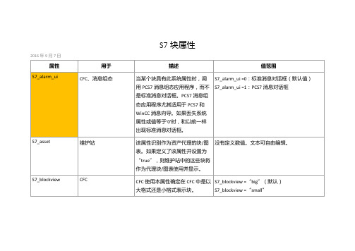
2016年9月7日
属性
用于
描述
值范围
S7_alarm_ui
CFC、消息组态
当某个块具有此系统属性时,调用PCS7消息组态应用程序,而不是标准消息对话框。PCS7消息组态应用程序尤其适用于PCS7和WinCC消息向导。如果丢失系统属性或值等于'0'时,和以前一样出现标准消息对话框。
S7_alarm_ui =0:标准消息对话框(默认值)
S7_tagcollect=“true”
S7_tagcollect ="false"(默认)
S7_tasklist
CFC
CFC使用本属性来确定是否在多个OB中包含一个块,从该属性中获取OB列表。该属性对于过程控制消息概念尤其重要。
S7_tasklist =‘OB1’包括块不超过一次
S7_techparam
分配技术参数
本属性识别具有本身参数分配接口的块
S7_pdiag_unit="true"
S7_pdiag_unit ="false"(默认)
S7_rawdata
WinCC
该属性描述了AS-OS工程是否不仅创建了块实例的变量还在WinCC中创建了一个原始数据变量。
S7_rawdata ="number1,number2",其中number2描述背景DB中原始数据变量的起始字节,number2包含长度。至少必须有一个接口连接到S7_m_c,块必须与操作员监控相关。
为某个块定义该属性时,语言编译器可以检测该UDT,并为该UDT生成附加信息。
S7_pdiag_s_unit='true'
S7_pdiag_s_unit ='false'(默认)
WAGO与西门子PLC通讯的使用说明(ProfiNet S7-1200 博途)

实验设备:PLC (S7-1200 CPU 1214C DC/DC/DC 6ES7214-1AG40-0XB0 Ver4.1)ProfiNet耦合器750-377 固件版本04IO(DI:750-430 8点;DO:750-530 8点;AI:750-455 4路;AO:750-555 4路)端板:750-600硬件设置:通过750-377上的DIP拨码(DIP8拨ON Device Name由DIP1-6决定)或软件(DIP8拨OFF)设置Device Name。
与节点地址无关。
例:DIP 8,1,2拨ON,则在“网络视图”中,双击从站,将“自动生成PROFINET设备名称”前的勾去掉,将PROFINET设备名称(Device Name)修改为如下:如果DIP 8,7,1,2拨ON,则PROFINET设备名称(Device Name)修改为如下:博途V13软件配置:1.新建项目(设定项目名称后,点击“创建”)2.组态配置(选择组态设备)3.添加设备(选择“添加新设备”,选择正确的型号和固件版本,完成后点击“添加”)4.添加ProfiNet网络(“设备视图”下,双击CPU,点击“添加新子网”,设置IP地址)软件自动生成一个ProfiNet子网“PN/IE_1”5.添加GSDML文件在弹出的对话框中选择需要安装的GSDML文件,点击“安装”6.添加ProfiNet从站(在“硬件目录”-“其他现场设备”-“PROFINET IO”下找到实际使用的从站,将其拖拽到“网络视图”中,注意从站的固件版本)7.设置从站模块(点击添加的从站单元,可设置从站的通信参数和设备名称等)8.添加从站IO(从“硬件目录”中找到实际连接的IO型号,将其拖拽至设备概览中)9.软件中连接主从站(“网络视图”下,点击从站的“未分配”,选择对应的主站,完成连接,根据主站的网段,从站自动分配)“拓扑视图”中,按硬件实际连接,完成连接。
SIMATIC S7-PDIAG V5.7 产品安全概述说明书
SIMATICS7-PDIAG V5.7, Tool for Configuring the ProcessDiagnosticsSecurity InformationSiemens provides products and solutions with industrial security functions thatsupport the secure operation of plants, systems, machines and networks.In order to protect plants, systems, machines and networks against cyber threats, it is necessary to implement - and continuously maintain - a holistic, state-of-the-art industrial security concept. Siemens’ products and solutions constitute one element of such a concept.Customers are responsible for preventing unauthorized access to their plants,systems, machines and networks. Such systems, machines and componentsshould only be connected to an enterprise network or the internet if and to theextent such a connection is necessary and only when appropriate securitymeasures (e.g. firewalls and/or network segmentation) are in place.For additional information on industrial security measures that may beimplemented, please visithttps:///industrialsecurity.Siemens’ products and solutions undergo continuous development to make them more secure. Siemens strongly recommends that product updates are applied as soon as they are available and that the latest product versions are used. Use of product versions that are no longer supported, and failure to apply the latestupdates may increase customer’s exposure to cyber threats.To stay informed about product updates, subscribe to the Siemens IndustrialSecurity RSS Feed underhttps:///industrialsecurity.Notes on Installation and UsageThe installation notes contain important information that you will require in order to install S7-PDIAG V5.7. Read these notes before installing the software.These notes should be considered more up-to-date than the information in other documents.Read the notes carefully, because they contain information on installing and using S7-PDIAG V5.7.Notes on Usage (Release Notes)These notes should be considered more up-to-date than the information in manuals and online helps.Please note that when printing the file that the borders for legal sized paper (DIN A4) in portrait format are set to about 25mm.ContentsContents1Contents of the Consignment2Hardware Requirements3Software Requirements3.1Operating Environment3.2Memory Requirements3.3Online Documentation3.4Upgrading an earlier version of S7-PDIAG3.4.1S7-PDIAG V5.7 Upgrade4Installation4.1Installing S7-PDIAG V5.74.2S7-PDIAG V5.7 License Key4.3Uninstalling S7-PDIAG V5.75New Features and Changes in the New Version6Notes on Configuring and Operating the Software6.1General Notes6.2S7-PDIAG V5.7 Technical Specifications6.2.1Released CPU Modules6.2.2Memory Requirement Estimation6.2.3Approximate Values of the Cycle Load6.2.4Number of Communication Nodes with Process Diagnostics6.3Libraries and Sample Projects6.4Notes on Working with S7-PDIAG6.4.1Address Priority6.4.2Virtual Unit Overview6.4.3Update Message Texts Using Symbol Table7Notes on Documentation7.1Help on S7-PDIAG7.2Printing the Help7.3Manual1 Contents of the ConsignmentThis DVD, part of the contents of the consignment, contains a complete version ofS7-PDIAG V5.7.This version is in 5 languages and can be run using the operating systems listedunder Chapter 3.1.S7-PDIAG V5.7 is supplied as a DVD in the content of consignment of a floating orupgrade license described below:S7-PDIAG V5.7, Floating LicenseOrder number: 6ES7840-0CC05-0YA5The following items are included in this package:• 1 DVD S7-PDIAG• 1 License key USB• 1 Certificate of LicenseS7-PDIAG Upgrade V5.7 (V5.3/V5.6 -> V5.7)Order number: 6ES7840-0CC05-0YE5The following items are included in this package:• 1 DVD S7-PDIAG• 1 License key USB• 1 Certificate of LicenseContents of the S7-PDIAG-DVD•S7-PDIAG V5.7•Product Notes: "S7-PDIAG-What's New.rtf"•"S7-PDIAG for S7-300 and S7-400 Configuring Process Diagnostics" for V5.3 Manual "Getting Started: First Steps with S7-PDIAG and ProAgent" Manual forV5.3The manuals are ready to install on the DVD.Important noteThe manuals are no longer updated. Please refer to the correspondingonline help for up-to-date information.2 Hardware RequirementsIn order to work with S7-PDIAG V5.7 you need a suitable programming device or asuitable PC. There are no special hardware requirements. Therefore, the minimumrequirements specific to the operating system apply. You can find theserequirements on the appropriate Microsoft websites.3 Software Requirements3.1 Operating EnvironmentOperating SystemsS7-PDIAG V5. 7 can be used with the following operating systems:•MS Windows 10 Pro and Enterprise (64-bit)•MS Windows Server 2016 (64-bit) (Standard Edition as work station computer)•MS Windows Server 2019 (64-bit) (Standard Edition as work station computer)S7-PDIAG has not been tested on any other operating systems; use at your ownrisk.Compatibility toolWith the compatibility tool, you can put together a compatible selection of softwareproducts or check existing configurations for compatibility. You can find thecompatibility tool at:https:///cs/ww/en/view/64847781STEP 7S7-PDIAG V5.7 runs on the STEP 7 basic package V5.7 (or higher).The hardware and software requirement for installing STEP 7 must be met (see theSTEP 7 readme file).Internet-ExplorerAll operating systems must be use MS Internet Explorer 6.0 (or higher).User RightsTo be able to work with S7-PDIAG in MS Windows 10/Server 2016/2019 you musthave logged on at least as the primary user. You must have administrator's rightsfor installing the S7-PDIAG software and also for setting up modules using the"Setting the PG/PC Interface" application.If S7-PDIAG is installed on an NTFS drive, the administrator has to grant all theprimary users working with S7-PDIAG full access to the S7-PDIAG installationdirectory. Use the "Security" tab for this. You can get to it via the Sharing andSecurity... menu command in the Windows Explorer context menu. If this tab isnot available under Windows, then you have to clear the "Simple File Sharing(recommended)" check box in the Windows Explorer via the Tools > Folderoptions... in the "View".If projects are saved on NTFS drives, all primary users have to be granted fullaccess.File systemsS7-PDIAG achieves a slightly lower performance when operating on a MSWindows NT file system (NTFS) as opposed to a FAT file system.3.2 Memory RequirementsS7-PDIAG Memory RequirementsDepending on the number of languages installed, S7-PDIAG V5.7 requiresapprox.24 MB and 26 MB of memory on your hard disk. The exact value alsodepends on your operating system and on the file system used on yourprogramming device/personal computer.3.3 Online DocumentationThe S7-PDIAG V5.7 online help is split into two sections.You can find notes on the current context in the same way as with the standardWindows help.The general section of the online help is based on the HTML format. You can findmore information on the structure of the documentation in Chapter 7 (in Notes onUsage) in the second half of this README file (S7-PDIAG-readme.rtf).3.4 Upgrading an earlier version of S7-PDIAG3.4.1 S7-PDIAG V5.7 UpgradeTo install the upgrade package, you require a valid license for S7-PDIAG V5.3 orV5.6.4 Installation4.1 Installing S7-PDIAG V5.7You can install S7-PDIAG V5.7 over a previously installed version of S7-PDIAGV5.6. You do not have to uninstall these versions of S7-PDIAG first.In order to obtain the optimum display of the information during the Setup, youshould set the color scheme in the control panel of your programmingdevice/personal computer to at least 65536 colors.Insert the S7-PDIAG-DVD in the drive. The setup program will guide you throughthe installation of S7-PDIAG. The setup program starts automatically after the S7-PDIAG-DVD has been inserted in the drive. If you have disabled this function onyour computer, start the setup program with MS Windows Explorer by double-clicking the SETUP.EXE program in the root directory.In the component selection box, select the components you want to install.These components will then be installed and entries will be made in MicrosoftWindows files.S7-PDIAG is automatically installed on the drive where STEP 7 is located.NoteS7-PDIAG registers itself in MS Windows system files. You cannot move orrename S7-PDIAG files or folders using Microsoft Windows utilities such as theExplorer or modify S7-PDIAG data in the Microsoft Windows registry. The programmay no longer run properly after such modifications.4.2 S7-PDIAG V5.7 License KeyBefore you can start working with S7-PDIAG, you have to transfer the license keyfrom the license key USB stick to the computer. There are two ways of doing this:•While you are installing S7-PDIAG, the Setup program displays a message if there is no suitable license key installed on your computer. You can thendecide whether you want the license key to be installed by the “Setup” programor whether you want to install the license key manually at a later time using the“Automation License Manager” program.•If the license key cannot be installed during setup, continue the Setup program without installing the license key. Install the license key after the S7-PDIAGinstallation via the Start menu (for example, Windows 7) Start > All Programs >Siemens Automation > Automation License Manager.The Automation License Manager has to be installed for the S7-PDIAG operation.NoteAs of S7-PDIAG V5.3 the license key can be installed on all local drives.The Automation License Manager prevents the authorizations and license keysfrom being installed on invalid drives or media such as RAM drives, diskettes orcompressed drives (i.e. DBLSPACE). If the drive in a device is reported as being a"removable medium" and not, as usual, as a "hard drive", it will be treated as aDVD, which means that no license keys may be installed on it.In the case of compressed drives, you can install the authorization on theassociated host drive.You absolutely have to follow the notes in the Automation License Manageralmreadme.rtf file on the S7-PDIAG Installation DVD.Hidden files are stored in the folder "<Drive, on which the authorization/license keyis installed>:\AX NF ZZ". These files and the folder must not be deleted, moved, orcopied. They contain data required for the authorization of your software.If you do not adhere to these guidelines, the authorization may be irretrievably lost.Notes on error-free use of the license keys•The License Key USB stick must not be read-only. Because the License Key USB stick is to be used without write protection, there is a danger that a viruscould be transferred from the hard disk to the USB stick. You should thereforerun a virus check on your PC or programming device every time you install orremove a license key.•If you use an optimizing program which enables you to move fixed blocks of memory, only use this option if you had previously moved the license key fromthe hard disk back to the License Key USB stick.•When you install a license key, a specially marked cluster appears on the target drive. Some test programs mark this cluster as "defective." Do not attempt torestore the defective cluster.•Do not forget to transfer the license key to the License Key USB stick before formatting, compressing, or restoring your hard disk or before installing a newoperating system.•If a backup copy of your hard disk contains copies of license keys, there is a danger that these copies may overwrite the valid installed license keys whenyou restore your backup data to the hard disk, thereby destroying the validlicense keys. To prevent a valid license key from being overwritten by a backupcopy, you must remove all license keys before you make a backup copy orexclude the license keys from the backup.Using the trial licenseIf there is no valid license key installed for S7-PDIAG V5.7, the default triallicensesupplied with S7-PDIAG is installed and used. This license key can be usedonly 21 days. With the first S7-PDIAG start without a valid license key, the triallicense is activated after confirmation.4.3 Uninstalling S7-PDIAG V5.7Software products must be removed according to Microsoft Windows conventions.Use the Microsoft Windows application "Add/Remove Programs" (in the taskbar inStart > Settings > Control Panel > Programs and Features) to remove yoursoftware package (for example, "SIMATIC S7-PDIAG V5.7").Alternatively, you can also uninstall using the setup program.These notes should be considered more up-to-date than the information inmanuals and online helps.5 New Features and Changes in the NewVersionWhat's New in Comparison to Version 5.6?Please read the "What's New" RTF file on S7-PDIAG found on the S7-PDIAGDVD.6 Notes on Configuring and Operating theSoftwareNotes on Usage (Release Notes)These notes should be considered more up-to-date than the information inmanuals and online helps.6.1 General NotesThe general notes on the STEP 7 V5.7 basic package and later are fully valid inconnection with S7-PDIAG.6.2 S7-PDIAG V5.7 Technical Specifications6.2.1 Released CPU ModulesYou require a S7-300/400/WinAC CPU with the message functions ALARM_S/ALARM_SQ (SFC 17/18) and ALARM_D/ALARM_DQ (SFC 107/108) to be able towork with S7-PDIAG.Please use the documentation to check the CPU you are using for the availabilityand specifications of ALARM_S/SQ and ALARM_D/DQ. S7-PDIAG requiresALARM_S or ALARM_SQ at least.6.2.2 Memory Requirement EstimationThe specified values are approximate values, they are dependent on thecomplexity of the networks to be monitored and on the monitoring logic.NoteYou cannot configure and use more than 10 groups because of the maximumblock size of 8 Kbytes with CPU 314/315.6.2.3 Approximate Values of the Cycle LoadYou will achieve a cycle load below 10ms with the number of monitoring givenbelow:•CPU 314/315: level monitoring with timer + 100 without timer•CPU 413/414: level monitoring with timer + 400 without timerIf you have configured groups, the cycle time per group will increase by•CPU 314/315: 1 ms•CPU 413/414: 0.6ms6.2.4 Number of Communication Nodes with Process DiagnosticsDepending on the CPU type, there are upper limits with the S7-CPUs as regardsthe nodes which can be logged on simultaneously for the message functions usedby S7-PDIAG.The possible number of communication nodes (OP / WinCC / PG) of the messagefunction ALARM_S / ALARM_SQ used by S7-PDIAG is determined by the CPUtype.Please check the number of communication nodes for S7 message functions inyour corresponding CPU documentation.6.3 Libraries and Sample ProjectsA library and a sample project are supplied with S7-PDIAG V5.7.These sample projects can be deleted in the SIMATIC Manager. To reinstall them,you have to run the S7-PDIAG V5.7 setup program again.NoteThe sample project and library shipped with S7-PDIAG V5.7 are always copiedwhen you install S7-PDIAG. If you have edited the standard sample projects, theywill be overwritten with the original examples if you reinstall S7-PDIAG V5.7.You should therefore make a copy of the standard examples before you makechanges to them and then make changes to the copy.6.4 Notes on Working with S7-PDIAG6.4.1 Address PriorityIf changes in symbols result in changes to process diagnosis data for which the setaddress priority is to be followed, then these changes will be made when a projectis opened with the application S7-PDIAG or when a block with diagnostic capabilityis opened in the LAD/FBD/STL editor.These changes are not made in the symbol editor.6.4.2 Virtual Unit OverviewIf the view "Virtual unit overview" is disabled, you will only be able to moveinstances to other groups via the Group.6.4.3 Update Message Texts Using Symbol TableIn S7-PDIAG a symbol name or comment is configured as a message. If themessage text is changed manually in the symbol table or automatically using amultilingual tool, the message text will have to be compared with the symbol table.To do this, the check box for "Update Message Texts Using Symbol Table" (menucommand Options > Customize, Compile tab) in S7-PDIAG has to be activated.The update will then be performed during the generation of the process diagnosticseither via Process Diagnostics> Compile or Process Diagnostics > Compilecompletely.The activation of the check box in the customize dialog and generation is onlypossible if S7-PDIAG is installed.7 Notes on DocumentationComprehensive documentation on S7-PDIAG is available to you in the online helpfor S7-PDIAG. You will find the S7-PDIAG "basic information" in the HTML-based"Help on S7-PDIAG".The basic information and the reference information are both available to you aselectronic manuals.This means that you have the choice between calling information exclusively fromthe online help or printing out individual chapters in order to read this informationlater on.7.1 Help on S7-PDIAGIn S7-PDIAG, you can activate the "Help on S7-PDIAG" via the menu commandHelp > Contents. The "Help on S7-PDIAG" conveys basic knowledge as toworking with the S7-PDIAG software. You have the following search options:•You can navigate through the contents using the configuration tasks to be performed as your guide,•You can use Index by searching for topics,•You can use Search by entering single termsYou can find information on the menu commands and dialogs used, as well as thekeyboard controls or other application-specific information in the online help for S7-PDIAG.All the jumps within the Help on S7-PDIAG are in blue. The color changes as soonas the jump is activated.You can also find the "Help on S7-PDIAG" and the S7-PDIAG glossary via thebuttons of the same name on the upper margin of the help window.You can find the help on the application using the menu commands: Help >Context-Sensitive Help, Help > Introduction, Help > Getting Started or byselecting an object and pressing the button F1.7.2 Printing the HelpThe print function is available for both the "Help S7-PDIAG" and the applicationhelp. The scope of the information printed varies depending on whether you haveselected a single topic or a whole book in the contents page.7.3 ManualThe manual for S7-PDIAG can be accessed at Start > All Programs >SiemensAutomation > …. It can be displayed and printed with a PDF reader.Keep in mind the form of the Start menu differs under the various operatingsystems.Due to the editorial deadline necessary in the creation of the product manuals,there may be an occasional slight difference between their content and that of theonline help.。
S7.PDIAG过程诊断功能介绍
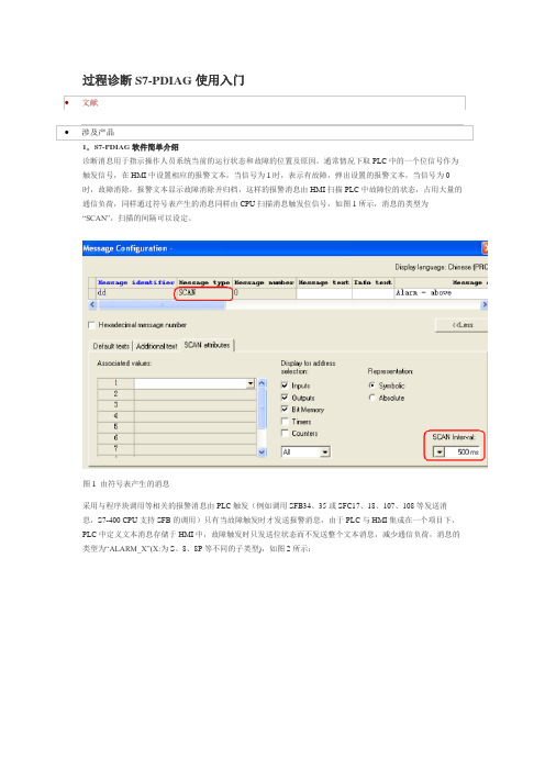
图1 由符号表产生的消息图2 块调用产生的消息S7-PDIAG软件通过内部调用系统函数SFC17、18、107、108完成消息的传送(SFC107、108替代SFC17、18,与之相比带有通信资源管理功能)。
2.S7-PDIAG软件诊断功能的种类S7-PDIAG包含三种诊断功能,分别是地址监控(Address monitoring)、全局监控(global monitoring或General monitoring)和运动监控(Motion monitoring),下面分别介绍这三种诊断功能。
2.1 地址监控地址监控功能监控一个位信号的状态变化,可以设定一个沿信号和电平信号,设置界面如图3所示:图3 地址监控功能设置界面在“Initial Diagnostic Address”设置监控的地址,如M1.1,然后选择监控的信号,如沿信号和电平信号,如果激活“Delay”功能,则需要设定相应的延迟时间,表示如果监控信号变化,将延迟设定的时间后触发,S7-PDIAG在程序内部调用SFC64,时间格式为IEC标准,例如T#1H19M12S100MS 表示的时间值为1小时19分12秒100毫秒,配置的延时定时器的个数没有限制。
在“Meassage”栏中设定信号触发的消息和优先级,配置完成后点击“OK”键确认。
2.2 全局监控全局地址监控功能监控一个表达式,如果表达式结果为1则触发消息,设置界面如图4所示:图4 全局监控功能设置界面在“Meassage”栏中设定信号触发的消息和优先级,配置完成后点击“OK”键确认。
2.3 运动监控运动监控对用户编写的定位过程进行监控,运动监控有下列几种监控方式:1)执行监控(Action Monitoring)当启动命令执行后,在设定的时间内没有到达定位的位置(限位信号),触发消息的生成。
执行监控的设置界面如图5所示:图5 运动监控-执行监控功能设置界面执行监控界面中使用S7-DIAG语言预先设定触发条件并不可以修改,如图5中,如果M1.2为1(执行),20秒后M1.1(限位开关)没有到达,触发报警消息。
- 1、下载文档前请自行甄别文档内容的完整性,平台不提供额外的编辑、内容补充、找答案等附加服务。
- 2、"仅部分预览"的文档,不可在线预览部分如存在完整性等问题,可反馈申请退款(可完整预览的文档不适用该条件!)。
- 3、如文档侵犯您的权益,请联系客服反馈,我们会尽快为您处理(人工客服工作时间:9:00-18:30)。
●号格式中的诊断输入地址
诊断输入地址的符号注释 (在消息文本中,可以
使用符号表内的符号注释来替换形式地址)
所组态CPU的名称。如果没有组态任何CPU,则将 任然保持形式地址,并且在编译时也不会将其替代
$$CpuName$$
插入过程值
在消息文本中可以插入一个故障触发时 的过程值,在“Record Associated Value”定义一 个过程值,如MD12,在文本中使用@1<元 素类型><格式定义>@替代MD12,输入的 消息文本为“ACTION FAILURE,PRESSURE VALUE = @1X%6D@”,如果MD12 为123,在HMI 显示 的文本为“ACTION FAILURE,PRESSURE VALUE =123”。 元素类型及格式定义的说明,见下表:
11111111111111111111111111111111
格式定义
描述
带i位数的十六进制数
显示范围
%[i]X
%[i]u
i位无符号十进制数
%[i]d
%[i]b %[i][-y]f %1s
i位有符号十进制数
i位二进制数
REAL数 字符
有符号值,格式为[-]dddd.dddd, dddd:小数点后带有“y”位数的一个 或多个数字以及总位数“i”
S7-PDiag操作界面
在SIMATIC Manager中单击Options>Configuer Process Diagnostics菜 单可进入S7-PDiag编辑界面,如下图:
下列图标
指示必须重新编译S7-PDIAG监视块
S7-PDiag的监视模式
S7-PDIAG:地址监视 S7-PDIAG:全局监视GLOSS_Allgemeine_berwachung S7-PDIAG:动作监视GLOSS_Aktions_berwachung S7-PDIAG:启动监视GLOSS_Anlauf_berwachung S7-PDIAG:响应监视GLOSS_Reaktions_berwachung S7-PDIAG:互锁监视GLOSS_Verriegelungs_berwachung
西门子S7-PDiag使用简介
S7-PDiag安装要求
S7-PDIAG V5.3运行在PC/PG上,在以下环境中: 操作系统Microsoft Windows、Windows 2000、 Windows XP、Windows Server 2003。 STEP 7标准软件,版本5.3。 S7 CPU必须包含SFC17和SFC18,否则S7-PDIAG将 无法处理Alarm_S,并且在下载块时会出现一条错 误消息
ProAgent
添加需要监视的块
编程实例
Step11
触摸屏设置完成后,模拟运行,可看到报警信息的显示。
注:监视模式的ቤተ መጻሕፍቲ ባይዱ体应用,详见S7-PDiag使用入门。
S7-PDIAG全局监视的语言说明
AND 与操作,例如表达式为 M1.1 AND M1.2,如果M1.1 与M1.2 为1, 表达式结果为1; ONDT 执行信号ON 延时,例如表达式为ONDT(M1.1,T#2S),如 果M1.1 为1 并延时2 秒后表达式结果为1; EN 存入下降沿结果,例如表达式为EN(M1.1),M1.1 产生下降沿时 表达式结果为1,M1.1 再次为1 时,表达式结果为0; EP 存入上升沿结果,与EN 相反; NOT 取反,例如表达式为NOT M1.1, 如果M1.1 为0 时表达式结果为1; OR 或操作,例如表达式为 M1.1 OR M1.2,如果M1.1 与M1.2 其中一 个为1,表达式果为1; SRT 置位复位延时,例如表达式为SRT(M1.1,M1.2 T#2S),如果M1.1 为1 (沿信号)2 秒后,表达式结果为1,如果如果M1.1 再次为1,表达式 结果为0,2 秒后表达式结果为1,如果M1.2 为1(沿信号),表达式 结果为0。 XOR 异或,例如表达式为M1.1 XOR M1.2,当M1.1 与M1.2 不相同时 表达式结果为1。
设置功能块的属 性为S7-PDiag, 值为true
编程实例
Step7
保存并退出FB块,在OB1中调用FB10,背景数据块为DB10,相应 的DB10的属性也会被系统自动设为S7-PDiag。
编程实例
Step8
进入S7-PDiag操作界面,可以看到定义为S7-PDiag属性的块。
编程实例
Step9
ANSI字符
编程实例
Step1 打开一个编辑好的FB块(此FB块可作为形参被其他块调用),选择你
需要监视的地址(可以是形参),右键单击该地址,选择 Special Object Properties>Monitoring
编程实例
Step2 在弹出的窗口中选择该地址需要使用的监视模式,在这里我们选择
在S7-PDiag操作界面进行编译,编译成功后可以看到报错信息 为“替代符号+消息模板”。
编程实例
Step10
在WinCC-flexible中打开ProAgent,把需要监视的块添加到触摸屏 中。(ProAgent只能运行在英文版的WinCC中,安装WinCC时应选 择英文为安装语言,由于ProAgent为可选插件,需要选择自定义安 装,手选ProAgent插件)
元素类型说明
元素类型 X C 数据类型
BOOL、BYTE、WORD、DWORD、INT、DINT
CHAR
R 格式定义说明 格式定义
%d %u %X %b
REAL
描述
有符号十进制数 无符号十进制数 十六进制 二进制
显示范围
-2147483648..+2147483647 0..4294967295 0..FFFFFFFF
编辑完成后的FB块,在右下角会 显示一个黄色的三角符号。
编程实例
Step5
新建一个FB块(FB10),调用刚刚编辑过的FB2功能块,FB2作为 一个静态变量被该FB块调用,名称分别为V1,V2。
编程实例
Step6
在FB10中点击File>Properties,修改功能块的属性,定义该功能 块为S7-PDiag属性。
S7-PDIAG 指令优先级
指令 () EP, EN, ONDT, SRT NOT 优先级 1 2 3
AND
XOR OR
4
5 6
S7-PDiag的替代功能
文本替代值
如果监控一个FB 块的形参,这个FB 块 又在其它的FB 块中作为形参多次调用,这 样在初始的FB 块定义的消息文本只能作为 一个模板,无法表示其它多次嵌套调用该 FB 而生成的消息文本,在消息文本模板中 使用$$替代符号$$,可在编译时生成“替 代符号+消息模板”的报警信息。替代符号 的定义见下表:
替代符号
$$u$$,$$u1$$
功能定义 高级单元的名称
树形结构中顶层单元的名称
至$$u9$$
$$ur$$ $$m$$ $$o$$
运动的名称
实例错误定义的诊断输入地址(如果在绝对格 式中不存在符号,则采用符号格式)
$$d1$$
$$d2$$ $$a$$ $$s$$ $$c$$
运动方向1的名称
运动方向2的名称
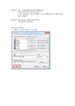
地址监控,点击“New”按钮。
编程实例
Step3
进入地址监控编辑界面。
设置监控的地址 设置监控的信号 设置延时,延时格式: T#1H19M5s20ms
替代文本
消息配置
设置优先级
插入过程值
编程实例
Step4
地址监控编辑完成后,在SIMATIC Manager 窗口该FB块显示为 S7-PDiag属性。